U.S. Pat. No. 9,498,716
Video game device and storage medium storing video game program
AssigneeNINTENDO CO., LTD.
Issue DateSeptember 5, 2006
Illustrative Figure
Abstract
A video game device successively obtains game data, which changes according to the state of the input device and is used in the game process. The video game device stores game data obtained at a point in time when the game process is paused. The video game device successively compares current game data with the stored game data, after starting to accept cancellation of the pause. The pause is canceled to resume the game process when a difference between a value of the current game data and a value of the game data stored in the storage means becomes smaller than a predetermined reference.
Description
DESCRIPTION OF NON-LIMITING EXAMPLE EMBODIMENTS (Configuration Of Game System) Referring toFIG. 1, a video game system1including a video game device according to an example embodiment of the present invention will now be described.FIG. 1shows an external view of the video game system1. A home-console type video game device will be described below as an example of the video game device of an example embodiment of the present invention. Referring toFIG. 1, the video game system1includes a home-console type video game device (hereinafter simply “video game device”)3and a controller7for giving control data to the video game device3. The video game device3is connected, via a connection cord, to a display (hereinafter “monitor”)2provided with a speaker, such as a home television receiver. Two markers8aand8bare provided around the monitor2(on the upper side of the screen in the illustrated example). Specifically, the markers8aand8bare infrared LEDs outputting infrared light to the front side of the monitor2. A receiver unit6is connected to the video game device3via a connection terminal. The receiver unit6receives control data wirelessly transmitted from the controller7, and the controller7and the video game device3are connected via wireless communications. In an alternative embodiment, the controller7and the video game device3may be connected via a wire. The video game system3includes an optical disc4, being an example of an information storage medium that can be received by the video game device3. Provided on the upper principal plane of the video game device3are an ON/OFF switch for turning ON/OFF the power of the video game device3, a reset switch for resetting a game process, and an OPEN switch for opening the upper lid of the video game device3. The lid opens up when the OPEN switch is pressed by the player so that the optical disc4can be put in place. The video game device3can also receive an external memory card5including ...
DESCRIPTION OF NON-LIMITING EXAMPLE EMBODIMENTS
(Configuration Of Game System)
Referring toFIG. 1, a video game system1including a video game device according to an example embodiment of the present invention will now be described.FIG. 1shows an external view of the video game system1. A home-console type video game device will be described below as an example of the video game device of an example embodiment of the present invention.
Referring toFIG. 1, the video game system1includes a home-console type video game device (hereinafter simply “video game device”)3and a controller7for giving control data to the video game device3. The video game device3is connected, via a connection cord, to a display (hereinafter “monitor”)2provided with a speaker, such as a home television receiver. Two markers8aand8bare provided around the monitor2(on the upper side of the screen in the illustrated example). Specifically, the markers8aand8bare infrared LEDs outputting infrared light to the front side of the monitor2. A receiver unit6is connected to the video game device3via a connection terminal. The receiver unit6receives control data wirelessly transmitted from the controller7, and the controller7and the video game device3are connected via wireless communications. In an alternative embodiment, the controller7and the video game device3may be connected via a wire. The video game system3includes an optical disc4, being an example of an information storage medium that can be received by the video game device3. Provided on the upper principal plane of the video game device3are an ON/OFF switch for turning ON/OFF the power of the video game device3, a reset switch for resetting a game process, and an OPEN switch for opening the upper lid of the video game device3. The lid opens up when the OPEN switch is pressed by the player so that the optical disc4can be put in place.
The video game device3can also receive an external memory card5including a backup memory, or the like, for statically storing save data, or the like. The video game device3executes a video game program, or the like, stored in the optical disc4to obtain a game image, and displays the obtained game image on the monitor2. The video game device3may reproduce a past game status from save data stored in the external memory card5to obtain a game image for that past game status, and display the obtained game image on the monitor2. Then, the player of the video game device3can enjoy the game process by operating the controller7while watching the game image displayed on the monitor2.
The controller7wirelessly transmits, from a communications section36(to be described later) therein, the control data to the video game device3, to which the receiver unit6is connected, by means of a technique such as Bluetooth (registered trademark), for example. The controller7has a control section, including a plurality of control buttons. As will later be apparent, the controller7includes an acceleration sensor37(to be described later) for detecting the acceleration in at least two orthogonal axial directions. Data representing the acceleration detected by the acceleration sensor37is transmitted to the video game device3as a part of the control data. The video game device3performs a predetermined operation on data representing the acceleration to calculate the inclination (orientation) of the controller7, and performs processes according to the inclination. The controller7includes an image capturing/processing section35(to be described later) for capturing an image as viewed from the controller7. Specifically, the image capturing/processing section35takes an image of the markers8aand8bprovided around the monitor2. The video game device3performs processes according to the position and the orientation of the controller7by performing calculations based on the image.
Referring now toFIG. 2, a configuration of the video game device3will be described.FIG. 2is a functional block diagram showing the video game device3.
Referring toFIG. 2, the video game device3includes a RISC CPU (Central Processing Unit)10, for example, for executing various programs. The CPU10executes a boot program stored in a boot ROM (not shown), thus initializing memory devices, such as a main memory13, and then executes a video game program stored in the optical disc4to perform a game process, etc., according to the video game program. Connected to the CPU10via a memory controller11are a GPU (Graphics Processing Unit)12, the main memory13, a DSP (Digital Signal Processor)14, and an ARAM (Audio RAM)15. The memory controller11is connected, via a predetermined bus, to a controller I/F (interface)16, a video I/F17, an external memory I/F18, an audio I/F19and a disk I/F21, which are connected to the receiver unit6, the monitor2, the external memory card5, the speaker22and a disk drive20, respectively.
The GPU12is responsible for image processing based on instructions from the CPU10, and is a semiconductor chip, for example, capable of computations necessary for 3D graphics display. The GPU12performs the image process by using a memory dedicated for image processing (not shown) or a part of the memory area of the main memory13. The GPU12produces game image data or movie data to be displayed on the monitor2using these memory areas, and outputs the produced data to the monitor2via the memory controller11and the video I/F17as necessary.
The main memory13is a memory area used by the CPU10, and stores a video game program, etc., as necessary for processes performed by the CPU10. For example, the main memory13stores the video game program loaded from the optical disc4by the CPU10and various data, etc. The video game program, the various data, etc., stored in the main memory13are executed or processed by the CPU10.
The DSP14is for processing sound data, etc., produced by the CPU10when executing the video game program, and is connected to the ARAM15for storing the sound data, etc. The ARAM15is used when the DSP14performs a predetermined process (e.g., storing a video game program, sound data, etc., which have been loaded in advance). The DSP14reads out the sound data stored in the ARAM15, and outputs the sound data through the speaker22provided in the monitor2via the memory controller11and the audio I/F19.
The memory controller11is responsible for the overall control of data transfers, and is connected to the various I/F's described above. The controller I/F16includes, for example, four controller I/F portions, each having a connector into which an external unit can be fitted for communicable connection between the external unit and the video game device3. For example, the receiver unit6may be fitted into the connector to be connected to the video game device3via the controller I/F16. As described above, the receiver unit6receives control data from the controller7, and outputs the control data to the CPU10via the controller I/F16. In an alternative embodiment, the video game device3may include therein, instead of the receiver unit6, a receiver module for receiving control data transmitted from the controller7. In such a case, the transmitted data received by the receiver module is outputted to the CPU10via a predetermined bus. The monitor2is connected to the video I/F17. The external memory card5is connected to the external memory I/F18, whereby a backup memory, etc., provided in the external memory card5can be accessed. The audio I/F19is connected to the speaker22provided in the monitor2so that the sound data read out from the ARAM15by the DSP14or the sound data outputted directly from the disk drive20can be outputted through the speaker22. The disk I/F21is connected to the disk drive20. The disk drive20reads out data from the optical disc4placed in a predetermined read-out position, and outputs the data to the bus or the audio I/F19of the video game device3.
Referring now toFIGS. 3A to 8, the controller7will be described.FIGS. 3A to 4are perspective views showing the external configuration of the controller7.FIG. 3Ais a perspective view showing the controller7as viewed from the upper rear side, andFIG. 3Bis a perspective view showing the controller7as viewed from the lower rear side.FIG. 4shows the controller7as viewed from the front side.
Referring toFIGS. 3A to 4, the controller7includes a housing31formed by plastic molding, for example. The housing31has a generally rectangular parallelepiped shape, with the longitudinal direction being the front-rear direction (the Z-axis direction shown inFIG. 3), and has an overall size such that it can be held in a hand of an adult or a child. The player can use the controller7for game operations by pressing buttons provided on the controller7, changing the inclination (the angle with respect to the direction of gravity) of the controller7itself, and changing the position and direction of the controller7itself. For example, the player can operate the controlled object in the game space (e.g., a character51to be described later) by changing the inclination of the controller7. The player can operate the controlled object by turning the controller7about an axis in the longitudinal direction and changing the position on the screen pointed at by the controller7. As used herein, “the position on the screen pointed at by the controller7” is ideally the position at which the straight line extending in the longitudinal direction from the front end of the controller7crosses the screen of the monitor2. However, it does not have to be precisely the position as long as a position in the vicinity thereof can be calculated by the video game device3. Hereinafter, the position on the screen pointed at by the controller7will be referred to as the “position pointed at by the controller7”. Moreover, the longitudinal direction of the controller7(the housing31) may hereinafter be referred to as the “pointing direction of the controller7”.
The housing31includes a plurality of control buttons. Provided on the upper surface of the housing31are a cross-shaped key32a, an X button32b, a Y button32c, a B button32d, a select switch32e, a menu switch32fand a start switch32g. A depressed portion is formed on the lower surface of the housing31, and an A button32iis provided on a slope on the rear side of the depressed portion. Each of these buttons (switches) is assigned a function as specified in the video game program executed by the video game device3, the details of which will not be discussed herein as being not directly related to the description of example embodiments of the present invention. A power switch32hfor turning ON/OFF the power of the video game device3from a remote position is provided on the upper surface of the housing31.
Moreover, the controller7includes the image capturing/processing section35(FIG. 5B), and a light receiving port35aof the image capturing/processing section35is provided on the front side of the housing31as shown inFIG. 4. A connector33is provided on the rear side of the housing31. The connector33is, for example, a 32-pin edge connector, and may be used for connecting other units to the controller7. Moreover, a plurality of LEDs34are provided on the upper surface of the housing31near the rear end. The controller7is given a controller ID (number) for identifying the controller7from others. The LEDs34are used for notifying the player of the controller ID being currently assigned to the controller7. Specifically, when control data is transmitted from the controller7to the video game device3, one of the LEDs34is lit depending on the controller ID.
Referring now toFIGS. 5A and 5B, an internal configuration of the controller7will be described.FIGS. 5A and 5Bshow an internal configuration of the controller7.FIG. 5Ais a perspective view showing the controller7with an upper casing (a part of the housing31) taken off.FIG. 5Bis a perspective view showing the controller7with a lower casing (a part of the housing31) taken off.FIG. 5Ashows one side of a substrate300, andFIG. 5Bshows the other side thereof.
InFIG. 5A, the substrate300is secured in the housing31, and the control buttons32ato32h, an acceleration sensor37, the LED34, a quartz oscillator46, a wireless module44, an antenna45, etc., are provided on the upper principal plane of the substrate300. These components are connected to a microcomputer42(seeFIG. 6) via lines (not shown) formed on the substrate300, etc. With the wireless module44and the antenna45, the controller7can function as a wireless controller. The quartz oscillator46generates a basic clock for the microcomputer42.
Referring toFIG. 5B, the image capturing/processing section35is provided at the front edge on the lower principal plane of the substrate300. The image capturing/processing section35includes an infrared filter38, a lens39, an image sensing device40and an image processing circuit41provided in this order from the front side of the controller7, and these components are provided on the lower principal plane of the substrate300. The connector33is provided at the rear edge on the lower principal plane of the substrate300. The A button32iis provided on the lower principal plane of the substrate300behind the image capturing/processing section35, and battery cells47are accommodated in a position further behind the A button32i. A vibrator48is provided on the lower principal plane of the substrate300between the battery cells47and the connector33. The vibrator48may be, for example, a vibrating motor or a solenoid. As the vibrator48is actuated, the controller7is vibrated, and the vibration is transmitted to the hand of the player holding the controller7, thus realizing a video game with vibration feed back.
Note that the shape of the controller7, and the shape, number and arrangement of the control buttons shown inFIGS. 3A to 5Bare all illustrative, and it is understood that example embodiments of the present invention can be carried out with any other suitable shape, number and arrangement. The position of the image capturing/processing section35in the controller7(the light receiving port35a of the image capturing/processing section35) does not have to be the front side of the housing31, but may be on any other side as long as light can be received from outside the housing31. Then, the “pointing direction of the controller7” is a direction perpendicular to the light receiving port, i.e., the image-capturing direction of the image sensing device40.
FIG. 6is a block diagram showing a configuration of the controller7. The controller7includes therein the acceleration sensor37mentioned above. The acceleration sensor37detects the acceleration (including the gravitational acceleration) of the controller7, i.e., the force (including the gravity) acting upon the controller7. Referring now toFIGS. 7 and 8, how acceleration is detected will be described in detail.
FIGS. 7 and 8show the relationship between the inclination of the controller7and the output of the acceleration sensor. The X′Y′Z′ coordinate system shown inFIGS. 7 and 8is a Cartesian coordinate system based on the controller7, which rotates as the controller7is turned and whose origin moves as the controller7is moved. The upward direction of the controller7is the positive Y′-axis direction, the forward direction is the positive Z′-axis direction, and the leftward direction (when facing forward) is the positive X′-axis direction.
Referring toFIGS. 7 and 8, the acceleration sensor37detects the acceleration in each of three axial directions of the up/down direction of the controller7(the Y′-axis direction shown inFIG. 7), the left/right direction (the X′-axis direction shown inFIG. 7) and the forward/backward direction (the z′-axis direction shown inFIG. 7). The acceleration sensor37detects the linear acceleration along each axis, and the output of the acceleration sensor therefore represents the acceleration value for each axis. Therefore, the detected acceleration is represented as a three-dimensional vector in the X′Y′Z′ coordinate system defined based on the controller7(seeFIGS. 7 and 8).
FIG. 7shows a state where the gravitational acceleration (the vector Va shown inFIG. 7) is oriented in the downward direction of the controller7. InFIGS. 7 and 8, it is assumed that the controller7is stationary. In the state shown inFIG. 7, the acceleration value (hereinafter the “acceleration vector”) Va detected by the acceleration sensor37is oriented in the negative Y′-axis direction. Then, in the acceleration vector Va, only the Y′ coordinate takes a non-zero value, whereas the X′ coordinate and the Z′ coordinate are both zero.FIG. 8shows a state where the controller7is inclined so as to be turned about the Z′ axis from the position shown inFIG. 7. In the state shown inFIG. 8, the direction of the acceleration vector Va has changed from that shown inFIG. 7, whereby the X′ coordinate and the Y′ coordinate each take a non-zero value, and the z coordinate is zero since the turn is about the Z′ axis. As shown inFIGS. 7 and 8, the acceleration sensor37is capable of detecting acceleration values whose components are three axial directions of the controller7. Then, through software-based operations using computers such as the microcomputer42and the CPU10, operations are performed on the detected acceleration value while handling it as an acceleration vector made up of components of the three axial directions, thus calculating the inclination of the controller7.
Data (acceleration data) representing the acceleration detected by the acceleration sensor37is outputted to the microcomputer42. In the present embodiment, the acceleration sensor37outputs the acceleration-based values repeatedly (specifically, once per frame). The video game device3performs predetermined operations on the value while handling the value as an acceleration vector to thereby calculate the inclination (orientation) of the controller7, and performs a game process according to the inclination.
In the present embodiment, the magnitude of the acceleration detected by the acceleration sensor37while the controller7is being stationary, i.e., the magnitude of the acceleration detected by the acceleration sensor37when it only represents the gravitational acceleration, is 1. For example, the values of the components of the acceleration vector Va detected in the state shown inFIG. 7are (X′,Y′,Z′)=(0,1,0).
While the acceleration sensor37is typically a capacitance-coupling acceleration sensor, it may be an acceleration sensor of any other suitable type or a gyroscope, as long as it is capable of calculating the inclination of the controller7. While an acceleration sensor detects the linear acceleration along each axis, a gyroscope detects an angular velocity entailing rotation. Therefore, a gyroscope and an acceleration sensor cannot simply be replaced by each other as they detect signals of different natures. In order to calculate the inclination using a gyroscope instead of an acceleration sensor, substantial changes need to be made. Specifically, the value of the inclination is initialized at the beginning of the detection. Then, the angular velocity data outputted from the gyroscope are integrated together. Then, by using the result of integration, the amount of change in the inclination with respect to the initial value is calculated. The calculated inclination is represented in angle.
As already described above, where the inclination is calculated by an acceleration sensor, the inclination is calculated by comparing the value of a component of the gravitational acceleration for each axis with a predetermined reference. Therefore, the calculated inclination can be represented by a vector, and an absolute direction can be detected without initialization. This is a difference between an acceleration sensor and a gyroscope. Moreover, they calculate the inclination in values of different natures, i.e., one being an angle and the other being a vector. Therefore, when an acceleration sensor is replaced by a gyroscope, it is necessary to perform a predetermined conversion on the inclination data.
Referring back toFIG. 6, the controller7includes a control section32(the control buttons), the image capturing/processing section35, and the communications section36, in addition to the acceleration sensor37.
The image capturing/processing section35is a system for analyzing image data obtained by image capturing means to determine each spot with high luminance and then to calculate the centroid, the size, etc., of the spot. The image capturing/processing section35has a sampling frequency of about 200 frames per second, for example, and is thus capable of following fast movements of the controller7.
Specifically, the image capturing/processing section35includes the infrared filter38, the lens39, the image sensing device40and the image processing circuit41. The infrared filter38passes only an infrared portion of incident light entering the controller7from the front side. The markers8aand8bprovided around the display screen of the monitor2are infrared LEDs outputting infrared light to the front side of the monitor2. Therefore, with the provision of the infrared filter38, it is possible to more accurately take the image of the markers8aand8b. The lens39condenses the infrared light passing through the infrared filter38, and outputs the condensed infrared light onto the image sensing device40. The image sensing device40is a solid-state image sensing device, such as a CMOS sensor or a CCD, for capturing the infrared light condensed through the lens39. Therefore, the image sensing device40produces image data by capturing only the infrared light that has passed through the infrared filter38. The image obtained by the image sensing device40will hereinafter be referred to as the “captured image”. The image data produced by the image sensing device40is processed in the image processing circuit41. The image processing circuit41calculates the positions of the imaging targets (the markers8aand8b) in the captured image. Referring now toFIG. 9, a method for calculating the position of the imaging target will be described.
FIG. 9shows an example of a captured image. In the captured image A1ofFIG. 9, an image8a′ of the marker8aand an image8b′ of the marker8bare arranged in a left-right arrangement. When the captured image is input, the image processing circuit41first calculates the coordinates representing the position of each region in the captured image that satisfies a predetermined condition. The predetermined condition is a condition for identifying the image of the imaging target (the target image). Specifically, the predetermined condition is that the region has a luminance greater than or equal to a predetermined value (a high-luminance region) and the size of the region is within a predetermined range. The predetermined condition is not limited to any particular condition as long as it is for identifying the imaging target, and may include a condition regarding the color of the image in an alternative embodiment.
When calculating the position of the target image, the image processing circuit41first identifies a high-luminance region of the captured image as a candidate target image. This is because a target image is present as a high-luminance region in the image data of the captured image. Then, based on the size of the identified high-luminance region, the image processing circuit41performs a determination process for determining whether or not the high-luminance region is a target image. In addition to images8a′ and8b′ of the two markers8aand8bbeing target images, the captured image may include images other than the target images, e.g., sunlight coming in through a window or light from a fluorescent light. Then, images other than the images8a′ and8b′ of the markers8aand8bmay appear as high-luminance regions. The determination process is for accurately identifying target images by distinguishing the images8a′ and8b′ of the markers8aand8bbeing target images from others. Specifically, in this determination process, it is determined whether or not the size of the identified high-luminance region is in a predetermined range. If the size of the high-luminance region is within the predetermined range, it is determined that the high-luminance region represents a target image. If the size of the high-luminance region is not within the predetermined range, it is determined that the high-luminance region represents an image other than the target image.
If a high-luminance region is determined to represent a target image in the determination process, the image processing circuit41calculates the position of the high-luminance region. Specifically, the image processing circuit41calculates the centroid of the high-luminance region. The centroid can be calculated on a scale finer than the resolution of the image sensing device40. It is assumed herein that the image taken by the image sensing device40has a resolution of 126×96, and the centroid is calculated on a 1024×768 scale. Therefore, the position of the centroid is represented by a set of coordinates ranging from (0,0) to (1024,768). Note that a position in the captured image is represented in a coordinate system (xy coordinate system) where the upper left corner of the captured image is the origin, the downward direction is the positive y-axis direction, and the rightward direction is the positive x-axis direction, as shown inFIG. 9.
As described above, the image processing circuit41calculates the coordinates representing the position of each region in the captured image that satisfies a predetermined condition. The position calculated by the image processing circuit41may hereinafter be referred to as the “marker position”. The marker position is the position of the imaging target in the coordinate system for representing positions on the plane corresponding to the captured image. The image processing circuit41outputs the marker position to the microcomputer42of the communications section36. The data of the marker position is transmitted by the microcomputer42to the video game device3as control data. Since the marker position changes in response to changes in the direction and the position of the controller7itself, the video game device3can calculate the direction and the position of the controller7by using the coordinates of the marker position. In the present embodiment, processes up to the process of calculating the marker position from the captured image are performed by the image processing circuit41and/or the microcomputer42of the controller7. Alternatively, the captured image may be sent to the video game device3, and processes equivalent to the subsequent processes may be performed by the CPU10of the video game device3, etc.
The control section32represents the various control buttons32ato32idescribed above, such as the cross-shaped key32a, and outputs data representing the input status of the control buttons32ato32i(whether each of the control buttons32ato32ihas been pressed) to the microcomputer42of the communications section36.
The communications section36includes the microcomputer42, a memory43, a wireless module44and an antenna45. The microcomputer42controls the wireless module44for wirelessly transmitting data obtained by the microcomputer42while using the memory43as a memory area.
The data outputted from the control section32, the acceleration sensor37and the image capturing/processing section35to the microcomputer42are temporarily stored in the memory43. Data are wirelessly transmitted from the communications section36to the receiver unit6at regular intervals. Since the game process typically proceeds in a cycle of 1/60 second (being one frame), the interval is preferably less than or equal to 1/60 second. At the transmission timing for transmitting data to the receiver unit6, the microcomputer42outputs, as control data, data stored in the memory43to the wireless module44. The wireless module44uses a technique such as Bluetooth (registered trademark) to modulate a carrier of a predetermined frequency with the control data, and radiates the weak radio wave signal from the antenna45. Thus, the control data is modulated by the wireless module44into a weak radio wave signal and transmitted from the controller7. The weak radio wave signal is received by the receiver unit6of the video game device3. The video game device3can obtain the control data by demodulating and decoding the received weak radio wave signal. The CPU10of the video game device3performs the game process based on the obtained control data and the video game program.
By using the controller7, the player can perform game operations such as changing the inclination of the controller7, changing the position of the controller7itself, and turning the controller7, in addition to the conventional game operation of pressing control buttons. The game operation using the controller7will now be described.
FIG. 10generally shows how the player uses the controller10to perform a game operation. As shown inFIG. 10, when playing the game on the video game system1by using the controller10, the player holds the controller10in one hand. The markers8aand8bare arranged along the upper edge of the screen of the monitor2in parallel to the horizontal direction of the screen. The positions of the markers8aand8band the direction of the arrangement of the two markers8aand8bare not limited to those of the illustrated example. For example, the markers8aand8bmay be arranged along the lower edge of the screen, or the two markers8aand8bmay be arranged in the vertical direction of the screen. The player holds the controller7with the front side of the controller7(the side for receiving light to be sensed by the image capturing/processing section35) facing toward the markers8aand8b. The player performs a game operation by changing the inclination of the controller7, changing the position on the screen pointed at by the controller7(the pointed position), or changing the distance between the controller7and the markers8aand8b.
(First Example)
A specific example of a video game played by using the video game system1will now be described. The first embodiment is a video game in which the game operation is performed by using the output of the acceleration sensor37(acceleration vector). In the first embodiment, the data output from the image capturing/processing section35is not used in the game operation, and the controller7may be a controller not including the image capturing/processing section35. Then, the markers8aand8bprovided around the screen of the monitor2are not necessary. In the first embodiment, the inclination of the controller7with respect to the turn thereof about the Z′ axis is calculated. Therefore, the acceleration sensor37is only required to detect at least the acceleration in two axial directions, i.e., the X′-axis direction and the Y′-axis direction, among the three axial directions shown inFIG. 7.
FIG. 11shows an example of a game image in the first embodiment. The video game of the first embodiment is a video game in which the player turns the character51(see arrows inFIG. 11) in a virtual three-dimensional game space (which may be a two-dimensional game space). In the first embodiment, the video game device3turns the character51about a predetermined axis in the three-dimensional game space in response to the turn of the controller7about the Z′ axis. Thus, the inclination of the character51displayed on the screen of the monitor2is determined based on the inclination of the controller7in the X′-axis direction and the Y′-axis direction. The game state where a normal game process (the process of turning the character51in response to the tilting of the controller7in the first embodiment) is being performed is herein referred to as the “non-paused state”. In the following description of the first embodiment, “the inclination of the controller7in the X′-axis direction and the Y′-axis direction” may be referred to simply as “the inclination of the controller7”.
If the player performs an operation (a pause operation) of pressing the pause button (a button for instructing a pause, e.g., the start switch32g) in the non-paused state, the video game device3pauses the game process, and the game state transitions from the non-paused state to the paused state. The paused state is a state where the game process is being paused and where the period in which the pause-canceling operation is accepted has not started.FIG. 12shows an example of a game image in the paused state. In the paused state, the game process is being paused and not being performed, and the character51is therefore not turned. In the paused state, a pause image52is displayed on the screen of the monitor2. The pause image52is an image for notifying the player that the game process is being paused.
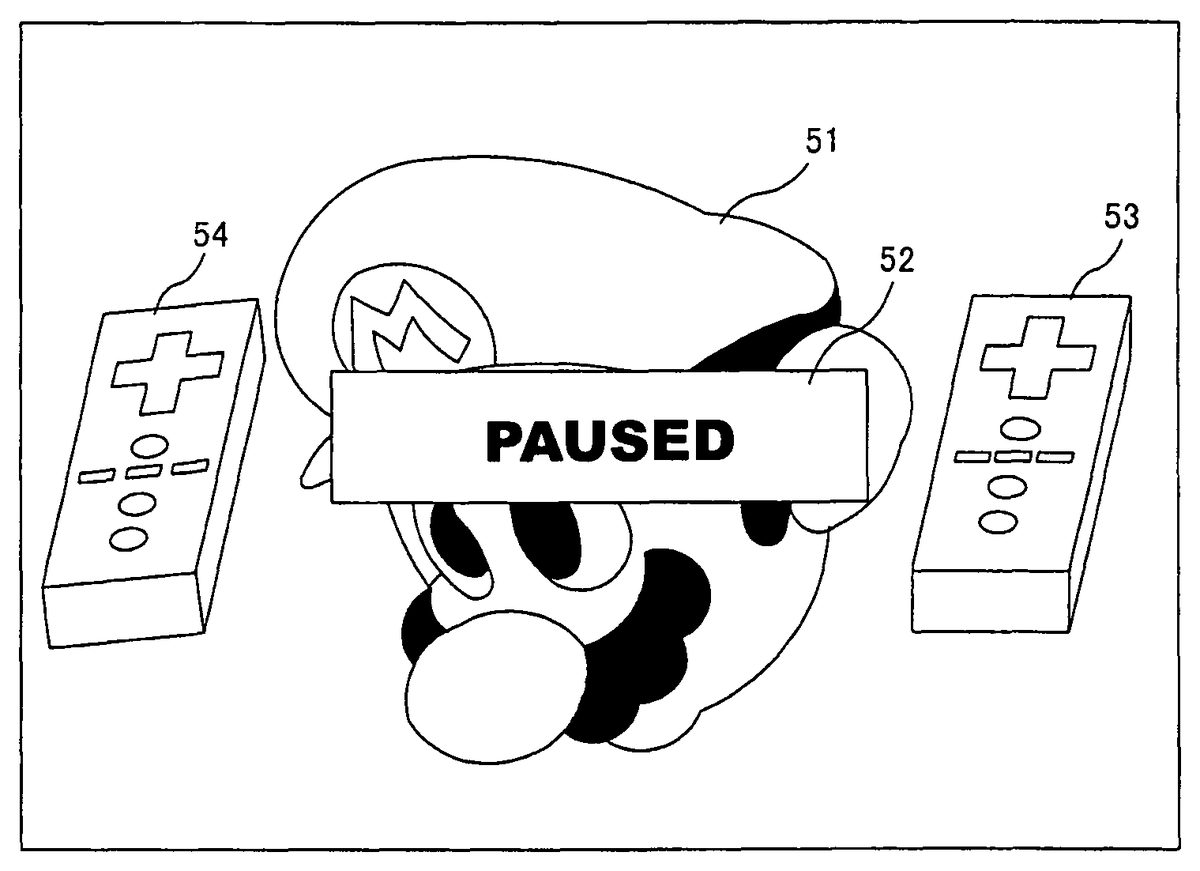
If the player presses a predetermined button (e.g., the select switch32e) in the paused state, the video game device3brings the game state from the paused state to the cancel-accepting state. The cancel-accepting state is a state where the game process is being paused and where the period in which the pause-canceling operation is accepted has started. Thus, the predetermined button is a button for instructing the transition of the game state from the paused state to the cancel-accepting state. The predetermined button will hereinafter be referred to as the “cancel-accepting button”. In order to resume the game from the paused state, the player first presses the cancel-accepting button to enter a state where pause cancellation is accepted.FIG. 13shows an example of a game image in the cancel-accepting state. In the cancel-accepting state, the video game device3displays two models53and54of the controller7on the screen of the monitor2. The first model53represents the current state of the controller7. When the player changes the inclination of the controller7in the cancel-accepting state, the video game device3accordingly changes the inclination of the first model53. The second model54represents the state of the controller7at the time when the game process was paused.
In the cancel-accepting state, the video game device3determines whether or not the current inclination of the controller7coincides with the inclination at the time of the pause operation (at the time when the game process was paused). In the first embodiment, the video game device3determines that the current inclination and the inclination at the pause operation coincide with each other as long as the difference between the two inclinations is smaller than a predetermined reference even if the two inclinations do not completely coincide with each other. If it is determined that the inclinations coincide with each other, the video game device3cancels the pause. Therefore, the player, who wishes to resume a game, controls the controller7so that the inclination of the controller7coincides with the inclination at the time of the pause operation. As described above, in the cancel-accepting state, the models53and54are displayed, and therefore the player can control the controller7while watching the models53and54so that the inclination of the first model53coincides with the inclination of the second model54.
FIG. 14shows an example of a game image when the pause is canceled. As shown inFIG. 14, when the pause is canceled, the inclination of the first model53and the inclination of the second model54generally coincide with each other. When the pause is canceled, the pause image52and the models53and54are erased (no longer displayed on the screen) InFIG. 14, the images being erased is represented by the use of dotted lines. Thus, as the pause is canceled, the game state transitions from the cancel-accepting state to the non-paused state, whereby the game process is resumed. Specifically, the video game device3resumes the game process in which the character51is turned in response to the tilting of the controller7.
As described above, in the first embodiment, after the game process is paused by the pause operation, the game process is resumed on the condition that the state of the controller7is close enough to that at the time of the pause operation. Thus, the state of the controller7when the game process is resumed is generally the same as that at the time of the pause operation. Therefore, it is possible to prevent a situation where the control operation when the pause is canceled is completely different from that at the time of the pause operation. Thus, it is possible to prevent the control operation from being different before and after the pause. For example, in the example shown inFIGS. 11 to 14, it is possible to prevent a situation where the character51, which is facing downward immediately before the pause, abruptly turns upward (a direction not expected by the player) upon canceling the pause. Being able to keep the state of the controller7generally the same before and after the pause is particularly advantageous in a video game that requires precise control operations (seeFIG. 27).
In the first embodiment, the player is not allowed to directly cancel the pause in the paused state, but needs to press the cancel-accepting button to first bring the game state to the cancel-accepting state, after which the player is allowed to cancel the pause in the cancel-accepting state. This prevents a situation where the game is resumed when it is not intended by the player. Specifically, it prevents a situation where when the player is not intending to resume the game, the inclination of the controller7accidentally coincides with the inclination at the time of the pause operation, thereby inadvertently resuming the game.
A program process performed by the video game device3in the first embodiment will now be described. First, important data to be used in the game process will be described with reference toFIG. 15.FIG. 15shows important data to be stored in the main memory13of the video game device3. Referring toFIG. 15, the main memory13stores a video game program61, control data62, pause process data63, etc. In addition to those shown inFIG. 15, the main memory13also stores other data necessary for the game process, such as image data of the character51to be in the game, and data representing various parameters of the character51.
At an appropriate point in time after the power of the video game device3is turned ON, part or whole of the video game program61is loaded from the optical disc4and stored in the main memory13. The video game program61includes a program needed for performing processes such as the game process of turning the character51according to the inclination of the controller7.
The control data62is transmitted from the controller7to the video game device3, and is stored in the main memory13. The control data62includes acceleration data621and control button data622. The acceleration data621is data representing the acceleration detected by the acceleration sensor37. Herein, the acceleration data621is data representing an acceleration vector for the three axial directions of X′, Y′ and Z′ shown inFIG. 7. The control button data622is data representing the input status of each of the control buttons32ato32i(whether the button has been pressed).
The pause process data63is data to be used when pausing the game process (to be described later) and when canceling the pause. The pause process data63includes game state data631, character direction data632, paused state data633, threshold value data634, first model data635, and second model data636.
The game state data631is data representing the current game state. As described above, in the present embodiment, there are three game states, i.e., “paused state”, “non-paused state” and “cancel-accepting state”. The game state data631indicates one of “paused state”, “non-paused state” and “cancel-accepting state”.
The character direction data632represents the direction (in the game space) of the character51being controlled by the player. Specifically, the character direction data632is three-dimensional vector data representing a direction in the three-dimensional game space.
The paused state data633represents the state of the controller7at the time when the game process is paused. In the first embodiment, the state of the controller7means the state of the controller7regarding the inclination thereof. Therefore, the paused state data633represents the acceleration vector at the point in time when the game process was paused.
The threshold value data634represents a threshold value to be used in the determination process performed in the cancel-accepting state, i.e., the determination process of determining whether or not the current inclination of the controller7coincides with the inclination at the time of the pause operation. The threshold value may be a predetermined fixed value specified in the video game program61, or a variable value determined by a player's instruction or based on other conditions.
The first model data635is data representing the direction of the first model. The second model data636is data representing the direction of the first model. As is the character direction data632, each of the model data635and636is three-dimensional vector data representing a direction in the three-dimensional game space.
Referring now toFIGS. 16 to 19, the details of the process performed by the video game device3will be described.FIG. 16is a main flow chart showing the process performed by the video game device3. When the power of the video game device3is turned ON, the CPU10of the video game device3executes a boot program stored in a boot ROM (not shown), thus initializing various units such as the main memory13. The video game program stored in the optical disc4is loaded to the main memory13, and the CPU10starts executing the video game program. The flow chart ofFIG. 16shows the process performed after the completion of the process described above. In the flow chart ofFIG. 16, parts of the process performed by the video game device3for pausing a game and for canceling the pause are shown in detail, and other parts of the game process that are not directly related to example embodiments of the present invention will not be shown in detail.
First, in step S1, data to be used in subsequent processes are initialized. Specifically, data representing the non-paused state is stored in the main memory13as the game state data631. Data representing a predetermined value specified in the video game program61is stored in the main memory13as the threshold value data634.
Then, in step S2, a game space is created and displayed on the monitor2. For example, the CPU10creates a three-dimensional game space, and places the character51to be present in the game space at a predetermined initial position. A game image representing the created game space, and the produced game image is displayed on the monitor2. Thereafter, the game proceeds as the loop through steps S3to S9is iterated once per frame.
In step S3, the CPU10obtains control data from the controller7. Specifically, the controller7transmits control data to the video game device3at a predetermined time interval (e.g., an interval of one frame), and the CPU10stores the transmitted control data in the main memory13. The control data at least includes the acceleration data and the control button data. The CPU10stores the acceleration data and the control button data in the main memory13. In the present embodiment, step S2is performed every frame, whereby the video game device3can successively obtain the acceleration data and the control button data.
Then, in step S4, the CPU10determines whether or not the current game state is the cancel-accepting state. The determination of step S4is performed by referring to the game state data631stored in the main memory13. Specifically, the determination result of step S4is positive if the game state data631represents the cancel-accepting state, and the determination result of step S4is negative if the game state data631represents a state other than the cancel-accepting state. If the determination result of step S4is positive, the process proceeds to step S8to be described later. If the determination result of step S4is negative, the process proceeds to step S5.
In step S5, the CPU10determines whether or not the current game state is the paused state. The determination of step S5is performed by referring to the game state data631stored in the main memory13. Specifically, the determination result of step S5is positive if the game state data631represents the paused state, and the determination result of step S5is negative if the game state data631represents a state other than the paused state. If the determination result of step S5is positive, the process proceeds to step S7to be described later. If the determination result of step S5is negative, the process proceeds to step S6. From the start of a game until the pause button is first pressed, the determination result is negative both in steps S4and S5, whereby the process proceeds to step S6.
In step S6, the non-paused state process is performed. The non-paused state process is a process for performing a normal game process (the process of turning the character51in response to the tilting of the controller7in the present embodiment). Referring now toFIG. 17, the details of the non-paused state process will be described.
FIG. 17is a flow chart showing the details of the non-paused state process (step S6) shown inFIG. 16. First, in step S11of the non-paused state process, the CPU10determines whether or not the pause button (the start switch32gin the first embodiment) has been pressed. The determination of step S11is performed by referring to the control button data622stored in the main memory13. Specifically, the determination result of step S11is positive if the control button data622indicates that the start switch32ghas been pressed, and the determination result of step S11is negative if the control button data622indicates that the start switch32ghas not been pressed. If the determination result of step S11is positive, the process proceeds to step S14to be described later. If the determination result of step S11is negative, the process proceeds to step S12.
While the non-paused state continues, the determination result of step S11is negative, and the process therefore proceeds to steps S12and S13. If the pause button is pressed in the non-paused state, the determination result of step S11becomes positive, and the process therefore proceeds to steps S14to S16.
In step S12, the game process is performed, by which the game proceeds. In the first embodiment, the game process is a process of turning the character51in response to the tilting of the controller7. Specifically, the CPU10determines the direction of the character51in the game space based on the direction of the acceleration vector represented by the acceleration data621stored in the main memory13. The method for calculating the direction of the character51is not limited to any particular method. For example, there may be a one-to-one correspondence between the direction of the acceleration vector and the direction of the character51. For example, the angle by which the character51is to be turned may be determined based on the amount of change in the acceleration vector (the difference between the acceleration vector in the current frame and the acceleration vector in the previous frame). Data representing the determined direction of the character51is stored as the character direction data632in the main memory13.
Then, in step S13, the CPU10produces a game image according to the processing results from step S12and displays the produced game image on the monitor2(FIG. 11). Thus, an image of the character51is displayed on the monitor2, wherein the character51is facing in the direction as determined in step S12. After step S13, the CPU10exits the non-paused state process.
In step S14, the game state is set to the paused state. Specifically, the CPU10updates the game state data631stored in the main memory13with a value representing the paused state. Therefore, in the next frame (the next iteration of steps S3to S9), the determination result of step S4is negative and the determination result of step S5is positive, and the process therefore proceeds to step S7. Thus, the game process of steps S12and S13is not performed, which means that the game process is being paused as a result of step S14.
Then, in step S15, the state of the controller7(the inclination of the controller7in the first embodiment) is stored. In the first embodiment, the CPU10stores data representing the current acceleration vector, i.e., the acceleration data621obtained in step S3, in the main memory13as the paused state data633. The data stored in step S15is not limited to any particular data as long as it represents the state of the controller7regarding the inclination thereof. For example, in step S15, data representing the direction of the character51may be calculated by a method similar to that of step S12, and stored in the main memory13as the paused state data633. For example, intermediate data obtained during the process of calculating the character direction data from the acceleration vector may be stored in the main memory13as the paused state data633.
Then, in step S16, the CPU10displays the game image of the game being paused on the monitor2. Specifically, the game image at the time when the game process was paused is displayed on the monitor2with the pause image52superimposed thereon (seeFIG. 12). The game image at the time when the game process was paused is the game image displayed in step S13in the previous frame. After step S16, the CPU10exits the non-paused state process.
As described above, when the player presses the pause button in the non-paused state (FIG. 11), the video game device3brings the game state to the paused state (step S14), and displays the game image of the game being paused on the monitor2(step S16, seeFIG. 12). Then, the video game device3stores the state of the controller7regarding the inclination thereof at the point in time when the game process is paused (step S15).
The process to be performed in the paused state will now be described.FIG. 18is a flow chart showing the details of the paused state process (step S7) shown inFIG. 16. First, in step S21of the paused state process, the CPU10determines whether or not the cancel-accepting button (the select switch32ein the present embodiment) has been pressed. The determination of step S21is performed by referring to the control button data622stored in the main memory13. Specifically, the determination result of step S21is positive if the control button data622indicates that the select switch32ehas been pressed, and the determination result of step S21is negative if the control button data622indicates that the select switch32ehas not been pressed. If the determination result of step S21is positive, the process proceeds to step S22to be described later. If the determination result of step S21is negative, the process proceeds to step S23, skipping step S22.
While the cancel-accepting button is the select switch32e, a different button from the pause button (the start switch32g) in the first embodiment, the cancel-accepting button and the pause button may be the same button in an alternative embodiment.
In step S22, the game state is set to the cancel-accepting state. Specifically, the CPU10updates the game state data631stored in the main memory13with a value representing the cancel-accepting state. Therefore, in the next frame (the next iteration of steps S3to S9), the determination result of step S4is positive, and the process therefore proceeds to step S8.
In step S23, the CPU10displays the game image of the game being paused on the monitor2. Specifically, the game image at the time when the game process was paused is displayed on the monitor2with the pause image52superimposed thereon (seeFIG. 12). After step S23, the CPU10exits the paused state process.
The process to be performed in the cancel-accepting state will now be described.FIG. 19is a flow chart showing the details of the cancel-accepting state process (step S8) shown inFIG. 16. As described above, if the cancel-accepting button is pressed in the paused state (Yes in step S21), the game state transitions to the cancel-accepting state (step S22), and the cancel-accepting state process is performed in the next frame.
First, in step S31of the cancel-accepting state process, the CPU10determines whether or not the pause button (the start switch32gin the first embodiment) has been pressed. The determination of step S31is the same as step S11. If the determination result of step S31is positive, the process proceeds to step S37to be described later. If the determination result of step S31is negative, the process proceeds to step S32.
In step S32, the CPU10compares the current state (inclination) of the controller7with the state (inclination) of the controller7at the time of the pause operation to determine whether or not they coincide with each other. The current inclination of the controller7is represented by the acceleration data621stored in the main memory13. The inclination of the controller7at the time of the pause operation is represented by the paused state data633stored in the main memory13. Thus, the CPU10compares the inclination represented by the acceleration data621with the inclination represented by the paused state data633. As described above, in the first embodiment, it is determined that the two inclinations coincide with each other as long as they are close enough to each other even though they do not completely coincide with each other.
Specifically, the CPU10calculates the magnitude of the difference between the vector represented by the acceleration data621and the vector represented by the paused state data633(i.e., the distance between the end points of the two vectors). Then, it is determined whether or not the magnitude is smaller than a predetermined threshold value. The threshold value is represented by the threshold value data634stored in the main memory13. If the magnitude of the difference is smaller than the threshold value, it is determined that the current inclination of the controller7and the inclination at the time of the pause operation coincide with each other. If the magnitude of the difference is greater than or equal to the threshold value, it is determined that the current inclination of the controller7and the inclination at the time of the pause operation do not coincide with each other.
The method for determining whether or not the current inclination of the controller7and the inclination at the time of the pause operation coincide with each other is not limited to the above method of calculating the magnitude of the difference. For example, it may be a method in which it is determined that the current inclination of the controller7and the inclination at the time of the pause operation coincide with each other if the angle between the two vectors is smaller than a predetermined value, whereas it is determined that the current inclination of the controller7and the inclination at the time of the pause operation do not coincide with each other if the angle is greater than or equal to the predetermined value.
If it is determined in step S32that the current inclination of the controller7and the inclination at the time of the pause operation coincide with each other, the process proceeds to step S33. If it is determined that the current inclination of the controller7and the inclination at the time of the pause operation do not coincide with each other, the process proceeds to step S35, skipping steps S33and S34.
In step S33, the CPU10determines whether or not the current acceleration vector is reliable. Herein, “an acceleration vector being reliable” means that the acceleration vector accurately represents the inclination of the controller7, i.e., the acceleration vector represents only the gravitational acceleration. When the controller7is being stationary, the acceleration sensor37used in the present embodiment represents only the gravitational acceleration, whereby the inclination of the controller7is accurately represented by the acceleration vector. When the controller7is being moved by the player, the acceleration sensor37detects an acceleration including not only the gravitational acceleration but also an acceleration caused by an inertial force being applied to the controller7. When such an acceleration is detected, the acceleration vector does not accurately represent the inclination of the controller7.
In the present embodiment, the CPU10determines whether or not the acceleration vector is reliable based on the magnitude of the acceleration vector. Specifically, it is determined that the acceleration vector is reliable if the magnitude of the acceleration vector is close to the magnitude of the gravitational acceleration (i.e., 1), and not reliable if the magnitude of the acceleration vector is not close to the magnitude of the gravitational acceleration. The determination of whether or not the magnitude of the acceleration vector is close to the magnitude of the gravitational acceleration can be performed based on whether the absolute value of the difference between the magnitude of the acceleration vector and the magnitude of the gravitational acceleration is smaller or larger than a predetermined value.
When the controller7is being moved by the player, the acceleration vector includes the component of the gravitational acceleration and the component of the acceleration caused by the inertial force being applied to the controller7, whereby the magnitude of the acceleration vector and the magnitude of the gravitational acceleration may differ substantially from each other. Therefore, the determination of step S33can be performed accurately by determining whether or not the acceleration vector is reliable based on the magnitude of the acceleration vector.
In an alternative embodiment, the determination of whether or not the acceleration vector is reliable may be performed based on the amount of change in the acceleration vector (or the direction of the acceleration vector). Specifically, the amount of change in the acceleration vector obtained in the current frame from the acceleration vector obtained in the previous frame may be calculated, and it may be determined that the acceleration vector is reliable if the amount of change is smaller than a predetermined amount.
If it is determined in step S33that the acceleration vector is reliable, the process proceeds to step S34. If it is determined that the acceleration vector is not reliable, the process proceeds to step S35, skipping step S34. In an alternative embodiment, the process may be proceeded to step S34only when the acceleration vector is determined to be reliable over a certain period of time (e.g., over a number of frames).
In step S34, the game state is set to the non-paused state. Specifically, the CPU10updates the game state data631stored in the main memory13with a value representing the non-paused state. Therefore, in the next frame (the next iteration of steps S3to S9), the determination result of step S4and the determination result of step S5are both negative, and the process therefore proceeds to step S6. Therefore, in the next frame (unless the pause button is pressed again), the game process of steps S12and S13is performed. Thus, the pause is canceled in step S34to resume the game process.
In step S35, the direction of each of the models53and54in the game space is calculated. The direction of each of the models53and54is calculated based on the acceleration vector by a method similar to that for calculating the direction of the character51. The direction of the first model53representing the current inclination of the controller7is calculated based on the current acceleration vector, i.e., the acceleration vector represented by the acceleration data621stored in the main memory13. The direction of the second model54representing the inclination of the controller7at the time of the pause operation is calculated based on the acceleration vector at the time of the pause operation, i.e., the acceleration vector represented by the paused state data633stored in the main memory13.
Then, in step S36, the CPU10displays the models53and54, in addition to the game image of the game being paused, on the monitor2(seeFIG. 13). The game image of the game being paused is the game image displayed in step S16. Thus, in the present embodiment, the models53and54are displayed in the cancel-accepting state. Therefore, the player can control the inclination of the controller7while referring to the models53and54so that the direction of the first model53and the direction of the second model54coincide with each other. Thus, the operation of canceling the pause is simplified. After step S36, the CPU10exits the cancel-accepting state process.
In step S37, the game state is set to the paused state. The specific process of step S37is the same as step S14shown inFIG. 17. As a result of step S37, the determination result of step S4is negative and the determination result of step S5is positive in the next frame (the next iteration of steps S3to S9), and the process therefore proceeds to step S7. This means that the game state has transitioned to the paused state. As described above, in the present embodiment, if the pause button is pressed in the cancel-accepting state, the game state returns back to the paused state.
Then, in step S38, the CPU10displays the game image of the game being paused on the monitor2(seeFIG. 12). The specific process of step S38is the same as step S23shown inFIG. 18. After step S38, the CPU10exits the cancel-accepting state process.
As described above, in the cancel-accepting state, the current inclination of the controller7and the inclination of the controller7at the time of the pause operation are compared with each other to determine whether or not they coincide with each other (step S32). If they coincide with each other, the game state transitions to the non-paused state (step S34), thereby resuming the game.
Referring back toFIG. 16, the process proceeds to step S9after step S6, S7or S8. Then, in step S9, the CPU10determines whether or not the game is over. The determination of step S9is based on, for example, whether the player has completed the game or whether a time limit has elapsed in a case where such a time limit is set in the game. If the determination result of step S9is negative, the process returns to step S3to repeat the loop through steps S3to S9until it is determined that the game is over. If it is determined that the determination result of step S9is positive, the CPU10exits the process shown inFIG. 16. The process performed by the video game device3is as described above.
As described above, in the first embodiment, when the game process is paused, the inclination (acceleration vector) of the controller7at the time of the pause operation is stored. Then, the current inclination of the controller7and the inclination of the controller7at the time of the pause operation are compared with each other, and the pause is canceled when the two inclinations coincide with each other. Thus, it is possible to ensure that when the pause is canceled to resume the game, the inclination of the controller7is the same as that before the game was paused. Therefore, in the first embodiment, it is possible to prevent a mistake by the player due to a sudden change in the game operation before and after a pause, thus improving the controllability.
In an alternative embodiment, the game process may be paused after the pause button is pressed only if the state of the controller7at the time of the pause operation is a state that can easily be reproduced by the player. If the state of the controller7at the time of the pause operation is a state that cannot easily be reproduced by the player, it will be difficult for the player to cancel the pause. A state of the controller7at the time of the pause operation that can easily be reproduced by the player is, for example, a state where the controller7is not being moved quickly. Whether or not the controller7is being moved quickly can be determined based on whether or not the magnitude of the acceleration vector, being the output of the acceleration sensor, is close to the magnitude of the gravitational acceleration.
(Second Embodiment)
The second embodiment is a video game in which the game operation is performed by using the output of the image capturing/processing section35(the marker position). In the second embodiment, the acceleration vector data outputted from the acceleration sensor37is not used in the game operation, and therefore the controller7may not include the acceleration sensor37.
FIG. 20shows an example of a game image in the second embodiment. The video game of the second embodiment is a video game in which the player operates a cursor55displayed on the screen so as to deform the character51provided in a virtual two-dimensional (or three-dimensional) game space. In the second embodiment, the video game device3moves the cursor55on the screen based on the position pointed at by the controller7(the position on the screen being pointed at by the controller7). Thus, the position of the cursor55on the screen is determined based on the pointed position. The cursor55will hereinafter be referred to as the first cursor55, as distinguished from a cursor56to be described later.
In the second embodiment, a normal game process is performed in the non-paused state, wherein the first cursor55is moved as the position pointed at by the controller7is changed, and the character51is deformed according to the position of the first cursor55. Specifically, in the non-paused state, the video game device3calculates the position pointed at by the controller7based on the marker position data contained in the control data transmitted from the controller7. Then, the first cursor55is moved to the pointed position calculated, and the character51is deformed according to the position of the first cursor55. In the example shown inFIG. 20, the nose of the character51is deformed according to the position of the first cursor55. Specifically, the first cursor55is located near the left end of the screen and, accordingly, the nose of the character51is deformed by being stretched leftward. In an alternative embodiment, the player may be allowed to deform any portion of the character51by first specifying the portion of character51(e.g., by moving the first cursor55to the intended position and pressing the B button32dof the controller7).
When the pause operation, in which the player presses the pause button (e.g., the start switch32g), is performed in the non-paused state, the video game device3pauses the game process and brings the game state from the non-paused state to the paused state.FIG. 21shows an example of a game image in the paused state in the second embodiment. In the paused state, the game process is paused and the game process is not performed, whereby the first cursor55is not moved and fixed at the position where it was at the time of the pause operation. As in the first embodiment, the pause image52is displayed on the screen of the monitor2in the paused state.
If the player presses the cancel-accepting button (e.g., the select switch32e) in the paused state, the video game device3transitions the game state from the paused state to the cancel-accepting state. Thus, as in the first embodiment, in order to resume the game from the paused state, the player first presses the cancel-accepting button.FIG. 22shows an example of the game image in the cancel-accepting state in the second embodiment. In the cancel-accepting state, the video game device3displays the second cursor56, different from the first cursor55, on the screen of the monitor2. The second cursor56represents the position being currently pointed at by the controller7.
In the cancel-accepting state, the video game device3determines whether or not the position being currently pointed at by the controller7coincides with the pointed position at the time of the pause operation. In the second embodiment, the video game device3determines that the current pointed position and the pointed position at the time of the pause coincide with each other as long as the two positions are close enough to each other even though they do not completely coincide with each other. If it is determined that the positions coincide with each other, the video game device3cancels the pause. Therefore, the player, who wishes to resume a game, controls the controller7so that the position pointed at by the controller7coincides with the pointed position at the time of the pause operation. As described above, in the cancel-accepting state, the two cursors55and56are displayed, and therefore the player can control the controller7while watching the cursors55and56so that the position of the second cursor56coincides with the position of the first cursor55.
FIG. 23shows an example of a game image when a pause is canceled in the second embodiment. Referring toFIG. 23, at the point in time when the pause is canceled, the position of the first cursor55and the position of the second cursor56substantially coincide with each other. When the pause is canceled, the pause image52and the second cursor56are erased (no longer displayed on the screen). InFIG. 23, the images being erased is represented by the use of dotted lines. Thus, as the pause is canceled, the game state transitions from the cancel-accepting state to the non-paused state, whereby the game process is resumed. Thus, the video game device3performs the process of moving the first cursor55as the position pointed at by the controller7is changed and deforming the character51according to the position of the first cursor55.
As described above, in the second embodiment, as in the first embodiment, after the game process is paused by the pause operation, the game process is resumed on the condition that the state of the controller7is close to the state at the time of the pause operation. Therefore, it is possible to prevent a situation where the control operation when the pause is canceled is completely different from that at the time of the pause operation. Thus, it is possible to prevent the control operation from being different before and after the pause.
In the second embodiment, the game process is performed using the position pointed at by the controller7. The position pointed at by the controller7changes according to the position and the orientation of the controller7, and can be said to be information representing the state of the controller7regarding the position and the orientation thereof. Thus, in the second embodiment, the state of the controller7regarding the position and/or the orientation thereof is calculated by the image capturing/processing section35, and the calculated result is used in the game process. The example embodiment of the present invention is applicable to a case where the state of the controller7is calculated by the image capturing/processing section35, as in the second embodiment.
A program process performed by the video game device3in the second embodiment will now be described. First, important data to be used in the game process will be described with reference toFIG. 24.FIG. 24shows important data to be stored in the main memory13of the video game device3in the second embodiment. InFIG. 24, like data to those shown inFIG. 15are denoted by like reference numerals and will not be further described below. Referring now toFIG. 24, the second embodiment will be described while focusing on what is different from the first embodiment.
Referring toFIG. 24, the main memory13stores the video game program61, the control data62, the pause process data63, etc., as in the first embodiment. In the second embodiment, the control data62includes marker position data623and the control button data622.
The marker position data623is data representing the position calculated by the image processing circuit41of the image capturing/processing section35, i.e., the marker position. The marker position is represented by a coordinate system for representing positions on the plane corresponding to the captured image (the xy coordinate system shown inFIG. 9).
In the second embodiment, the pause process data63includes the game state data631, the paused state data633, the threshold value data634, first cursor position data637, and second cursor position data638.
The first cursor position data637is data representing the position of the first cursor55on the screen. The second cursor position data638is data representing the position of the second cursor56on the screen.
As in the first embodiment, the paused state data633represents the state of the controller7at the point in time when the game process was paused. In the second embodiment, the state of the controller7refers to the state of the controller7regarding the position pointed at by the controller7. Therefore, in the second embodiment, the first cursor position data637at the point in time when the game process was paused is stored as the paused state data633.
The threshold value data634used in the second embodiment is data used for the same purpose as the threshold value data used in the first embodiment. Note however that the specific value of the threshold value data634in the second embodiment may differ from the value of the threshold value data in the first embodiment.
Referring now toFIGS. 25 and 26, the details of the game process performed by the video game device3in the second embodiment will be described. The main flow of the second embodiment is similar to that shown in the main flow chart ofFIG. 16, and will not therefore be further described below. Since the control data obtained in step S3in the second embodiment includes the marker position data and the control button data, the marker position data623and the control button data622are stored in the main memory13in step S3.
First, the non-paused state process of the second embodiment will now be described.FIG. 25is a flow chart showing the details of the non-paused state process in the second embodiment. First, in step S41of the non-paused state process, the CPU10determines whether or not the pause button (the start switch32gin the second embodiment) has been pressed. Step S41is the same as step S11in the first embodiment. If the determination result of step S41is positive, the process proceeds to step S44to be described later. If the determination result of step S41is negative, the process proceeds to step S42.
In step S42, the game process is performed, by which the game proceeds. In the second embodiment, the game process is a process of moving the first cursor55based on the position pointed at by the controller7, and deforming the character51according to the position of the first cursor55. Specifically, the CPU10determines the position pointed at by the controller7, i.e., the position of the first cursor55, based on the marker position represented by the marker position data623stored in the main memory13. The method for calculating the position pointed at by the controller7is not limited to any particular method, and may be a method as follows, for example.
An example of a method for calculating the position pointed at by the controller7will now be described. The marker position data623obtained from the controller7represents two marker positions corresponding to the markers8aand8b, and the CPU10first calculates the middle point between the two marker positions from the marker position data. The position of the middle point is represented by the xy coordinate system for representing positions on the plane corresponding to the captured image. Then, the CPU10converts the coordinates representing the position of the middle point to coordinates in the coordinate system for representing positions on the screen of the monitor2(the x′y′ coordinate system). Where the origin of the x′y′ coordinate system is the upper left corner of the screen, and the downward direction is defined to be the positive y-axis direction thereof while the rightward direction is defined to be the positive x-axis direction thereof, this conversion can be done as follows. The x′ coordinate of the pointed position can be obtained by reversing the sign of the x coordinate of the middle point and scaling it by a predetermined factor (e.g., a factor such that the length of the captured image in the x-axis direction in the xy coordinate system is made to coincide with the length of the screen in the x′-axis direction in the x′y′ coordinate system). The y′ coordinate of the pointed position can be obtained by scaling the y coordinate of the middle point by a predetermined factor (e.g., a factor such that the length of the captured image in the y-axis direction in the xy coordinate system is made to coincide with the length of the screen in the y′-axis direction in the x′y′ coordinate system). The conversion from the x coordinate to the x′ coordinate involves reversing the sign thereof because the movement direction of the middle point between the marker positions is opposite to the movement direction of the actual position pointed at by the controller7with respect to the left/right direction (the x-axis direction or the x′-axis direction). If the actual position pointed at by the controller7moves in the negative direction (the positive direction) of the x′-axis direction, the middle point between the marker positions moves in the positive direction (the negative direction) of the x-axis direction. The position represented by the calculated x′ and y′ coordinates is the position pointed at by the controller7. In an alternative method for more accurately calculating the pointed position, the image is rotated about the center of the image so that a vector extending between the two marker positions is parallel to the y axis, and the above conversion process is performed on the middle point between the two marker positions after the rotation. With such a correction operation by rotating the image, it is possible to accurately calculate the pointed position even in a case where the controller7is tilted, for example.
In the second embodiment, the position pointed at by the controller7, i.e., the position of the first cursor55, is calculated as described above. Data representing the calculated position of the first cursor55is stored in the main memory13as the first cursor position data637. In step S42, the CPU10deforms the character51according to the position of the first cursor55. Although not shown inFIG. 24, data representing shapes of the character being deformed are stored in the main memory13.
Then, in step S43, the CPU10produces a game image according to the processing results from step S42and displays the produced game image on the monitor2. Specifically, the first cursor55is displayed at the position determined in step S42, and the character51deformed in step S42is displayed on the monitor2(FIG. 20). After step S43, the CPU10exits the non-paused state process.
In step S44, the game state is set to the paused state. Step S44is the same as step S14in the first embodiment. As in the first embodiment, the game process is paused as a result of step S14.
Then, in step S45, the state of the controller7is calculated. Specifically, the position pointed at by the controller7is calculated in the second embodiment. The method for calculating the position pointed at by the controller7is the same as that in step S42. Data representing the calculated pointed position is stored in the main memory13as the first cursor position data637.
Then, in step S46, the state of the controller7calculated in step S45is stored. In the second embodiment, the CPU10stores data representing the position pointed at by the controller7, i.e., the first cursor position data637, in the main memory13as the paused state data633. The type of data stored in step S46is not limited to any particular type as long as it represents the state of the controller7regarding the position pointed at by the controller7. For example, the marker position data obtained in step S3may be stored as the paused state data633, or data representing the position of the middle point between the two marker positions obtained from the marker position data may be stored as the paused state data633. Alternatively, data representing the shape of the character51may be stored as the paused state data633, for example.
Then, in step S47, the CPU10displays the game image of the game being paused on the monitor2. Specifically, the game image at the time when the game process was paused is displayed on the monitor2with the pause image52superimposed thereon (seeFIG. 21). The game image at the time when the game process was paused is the game image displayed in step S43in the previous frame. After step S47, the CPU10exits the non-paused state process.
The paused state process in the second embodiment is similar to that of the first embodiment, and will not be further described below. The cancel-accepting state process of the second embodiment will now be described.FIG. 26is a flow chart showing the details of the cancel-accepting state process in the second embodiment.
First, in step S51of the cancel-accepting state process, the CPU10determines whether or not the pause button (the start switch32gin the second embodiment) has been pressed. Step S51is the same as step S31in the first embodiment. If the determination result of step S51is positive, the process proceeds to step S56to be described later. If the determination result of step S51is negative, the process proceeds to step S52.
In step S52, the current state of the controller7is calculated. In the second embodiment, the position pointed at by the controller7, i.e., the position of the second cursor56, is calculated as the current state of the controller7. The position of the second cursor56is calculated based on the marker position data623stored in the main memory13. The specific method for calculating the position of the second cursor56is the same as that for calculating the position of the first cursor55. Data representing the calculated position of the second cursor56is stored in the main memory13as the second cursor position data638.
Then, in step S53, the CPU10compares the current state (pointed position) of the controller7with the state (pointed position) of the controller7at the time of the pause operation to determine whether or not they coincide with each other. The position being currently pointed at by the controller7is represented by the second cursor position data638stored in the main memory13. The position pointed at by the controller7at the time of the pause operation is represented by the paused state data633stored in the main memory13. Thus, the CPU10compares the inclination represented by the second cursor position data638with the inclination represented by the paused state data633. As described above, in the second embodiment, it is determined that the two positions coincide with each other as long as they are close enough to each other even though they do not completely coincide with each other. Specifically, it is determined that the two positions coincide with each other if the distance therebetween is smaller than a value represented by the threshold value data634, and that they do not coincide with each other if the distance is greater than or equal to the threshold value.
If it is determined in step S53that the position being currently pointed at by the controller7and the pointed position at the time of the pause operation coincide with each other, the process proceeds to step S54. If it is determined that the position being currently pointed at by the controller7and the pointed position at the time of the pause operation do not coincide with each other, the process proceeds to step S55, skipping step S54.
In step S54, the game state is set to the non-paused state. Step S54is the same as step S34of the first embodiment. Therefore, in the next frame (unless the pause button is pressed again), the pause is canceled to resume the game process.
In step S55, the CPU10displays the second cursor56, in addition to the game image of the game being paused, on the monitor2(seeFIG. 22). The game image of the game being paused is the game image displayed in step S36. Thus, in the present embodiment, the two cursors55and56are displayed in the cancel-accepting state. Therefore, the player can control the position pointed at by the controller7(the position and/or the orientation of the controller7) while referring to the cursors55and56so that the position of the second cursor56and the position of the first cursor55coincide with each other. Thus, the operation of canceling the pause is simplified. After step S55, the CPU10exits the cancel-accepting state process.
In step S56, the game state is set to the paused state. Step S56is the same as step S37of the first embodiment. The game process is paused as a result of step S56. As described above, in the present embodiment, if the pause button is pressed in the cancel-accepting state, the game state returns back to the paused state.
Then, in step S57, the CPU10displays the game image of the game being paused on the monitor2(seeFIG. 12). Step S57is the same as step S38of the first embodiment. After step S57, the CPU10exits the cancel-accepting state process.
As described above, in the cancel-accepting state of the second embodiment, the position being currently pointed at by the controller7is compared with the position pointed at by the controller7at the time of the pause operation to determine whether or not they coincide with each other (step S53). If they coincide with each other, the game state transitions to the non-paused state (step S54), thereby resuming the game. The process performed by the video game device3in the second embodiment is as described above.
As described above, in the second embodiment, when the game process is paused, the position pointed at by the controller7(the cursor position) at the time of the pause operation is stored. Then, the position being currently pointed at by the controller7and the position pointed at by the controller7at the time of the pause operation are compared with each other, and the pause is canceled when the two positions coincide with each other. Thus, it is possible to ensure that when the pause is canceled to resume the game, the position pointed at by the controller7is the same as that before the game was paused. Therefore, in the second embodiment, as in the first embodiment, it is possible to prevent a mistake by the player due to a sudden change in the game operation before and after a pause, thus improving the controllability. In the second embodiment, the second cursor is displayed in the cancel-accepting state, thus making it easier for the player to cancel a pause. In the cancel-accepting state, only the second cursor is displayed, and the image of the character itself, determined based on the second cursor, is not displayed, thus reducing the processing load on the CPU10as compared with a case where the image of the character is displayed.
(Variation of Data Used in Game Process)
The first embodiment is directed to a game process performed based on the inclination (orientation) of the controller7, and the second embodiment is directed to a game process performed based on the position pointed at by the controller7changing according to the position or the orientation of the controller7. In an alternative embodiment, the game process may be performed based on the state of the controller7regarding at least one of the position and the orientation thereof. Herein, “the state of the controller7regarding at least one of the position and the orientation thereof” represents a concept encompassing the position of the controller7, the orientation thereof, the change in the position thereof (the velocity thereof), the change in the orientation thereof (the angular velocity thereof), etc. For example, the video game device3may calculate the position of the controller7to perform the game process using the calculated position, or may calculate the amount of change in the position or the orientation (the velocity or the angular velocity) of the controller7to perform the game process using the calculated amount of change.
For example, the video game device3can calculate the orientation of the controller7with respect to the rotation about the Z′ axis by using the marker positions calculated by the image capturing/processing section35. Specifically, when the controller7is turned about the Z′ axis, the direction along the line extending between the two marker positions turns as the controller7is turned. Therefore, the orientation can be calculated based on the direction along the line extending between the two marker positions. The video game device3may perform the game process based on the orientation. The video game device3can calculate the distance from the markers8aand8bto the controller7by using the marker positions calculated by the image capturing/processing section35. The length between the two marker positions increases as the controller7is moved closer to the markers8aand8b, and decreases as the controller7is moved away from the markers8aand8b. Therefore, the distance can be calculated based on the length between the two marker positions. The video game device3may perform the game process based on the distance.
The acceleration sensor37is used for calculating the inclination of the controller7in the first embodiment, and the image capturing/processing section35is used for calculating the position pointed at by the controller7in the second embodiment. In an alternative embodiment, any suitable sensor may be used for calculating the state of the controller7, which is to be reflected to the game process. In an alternative embodiment, the state of the controller7may be calculated using both the acceleration sensor37and the image capturing/processing section35. For example, the image capturing/processing section35may be used to calculate the position pointed at by the controller7, and the acceleration sensor37may be used to calculate the orientation of the controller7. Then, the game process is performed based on the position pointed at by the controller7and the orientation of the controller7. For example, where the orientation of the controller7with respect to the rotation about the Z′ axis is calculated, the orientation may be calculated by using both the acceleration sensor37and the image capturing/processing section35(specifically, selectively using one of them at a time). Specifically, the orientation may be calculated by using the marker position data obtained from the image capturing/processing section35in cases where the markers8aand8bcan be captured by the image capturing/processing section35, and the orientation may be calculated by using the acceleration vector obtained from the acceleration sensor37in cases where the markers8aand8bcannot be captured by the image capturing/processing section35.
(Variation of Game Data Stored Upon Pausing)
The output of the acceleration sensor (the acceleration vector) is stored at the time of the pause operation in the first embodiment, and the position pointed at by the controller7(the position of the first cursor55) is stored in the second embodiment. In an alternative embodiment, data to be stored at the time of the pause operation may be any suitable game data that is used in the game process and that changes according to the state of the controller7(regarding at least one of the position and the orientation thereof). Herein, the game data represents a concept encompassing data representing the state of the controller7(the acceleration data621, the first cursor position data637, and the marker position data623), and data calculated therefrom (the character direction data632, and data representing the shape of the character51). Where the game data to be stored and the game data representing the current state of the controller7are compared with each other in the step S32of the first embodiment or in the step S53of the second embodiment, the type of the game data representing the current state needs to be changed according to the type of the game data to be stored. For example, where the character direction data is to be stored, instead of the acceleration data, in the first embodiment, the current character direction data is calculated before step S32, and the calculated character direction data is compared with the stored character direction data.
(Variation of Guide Image)
In the cancel-accepting state, the models53and54are displayed in the first embodiment and the second cursor56is displayed on the second embodiment. The models and the cursor are images for guiding the player to the state of the controller7at the time of the pause operation. Thus, these images are displayed for the purpose of facilitating the player's operation of canceling the pause. The guide images are not limited to models or cursors, but may be, in an alternative embodiment, numerical values or arrows indicating how the operation can be done, for example. Specifically, in the first embodiment, there may be displayed a numerical value representing the angular difference between the inclination of the controller7at the time of the pause operation and the current inclination. In the second embodiment, there may be displayed an arrow indicating the direction in which the pointed position should be moved. In an alternative embodiment, the image of the controlled object may be displayed in the cancel-accepting state for guiding the player. This will now be described in detail with reference toFIGS. 27 and 28.
FIGS. 27 and 28each show an example of a game image in an alternative embodiment. InFIG. 27, plate-shaped objects71and72, a ball object73and a wall object74are arranged in a two-dimensional game space. The video game shown inFIG. 27is a hockey game in which the ball object73is hit between the plate-shaped object72, which is controlled by the CPU10of the video game device3, and the plate-shaped object71. The plate-shaped object71is an object controlled by the player (player object). The player can move and turn the plate-shaped object71in the up/down and left/right directions of the screen (see arrows inFIG. 27). Specifically, the plate-shaped object71is moved in the up/down and left/right directions of the screen according to the position pointed at by the controller7, and is turned according to the inclination of the controller7.
FIG. 28shows an example of a game image of the video game ofFIG. 27where the game has transitioned to the cancel-accepting state. InFIG. 28, the plate-shaped object71is fixed in the state at the time of the pause operation. The video game device3also displays a guide object75representing the state of a player object as calculated from the current state of the controller7. Specifically, in the cancel-accepting state, the video game device3calculates the position pointed at by the controller7to determine the position of the guide object75on the screen based on the calculated pointed position, and calculates the inclination of the controller7to determine the direction of the guide object75based on the calculated inclination. The video game device3determines whether or not the position of the plate-shaped object71and the position of the guide object75coincide with each other and the direction of the plate-shaped object71and the direction of the guide object75coincide with each other. If the positions coincide with each other and the directions coincide with each other, the pause is canceled to resume the game. As described above, if there are a plurality of types of states of the controller7(in the above example, there are two types: the position pointed at by the controller7, and the inclination of the controller7), it is preferred that the pause is canceled when each state at present coincides with that at the time of the pause operation. As shown inFIG. 28, the guide image may be an image of the controlled object.
Where the controlled object is moved around on the screen as in the second embodiment, there may be a situation where the controlled object is not displayed (or only a part of it is displayed) on the screen due to the settings of the display device (the monitor2), etc.FIG. 29shows an example of a game image in an alternative embodiment. InFIG. 29, it is assumed that only three cursors76to78are displayed for the sake of simplicity. The three cursors76to78shown inFIG. 29are the controlled cursor76, the guide cursor77, and the reference cursor78. The controlled cursor76is a cursor, which is the controlled object in the non-paused state.
In the example ofFIG. 29, the reference cursor78is being displayed at a predetermined distance upward from the controlled cursor76, which is being out of the screen, in the cancel-accepting state. The guide cursor77is displayed at the position determined based on the position being currently pointed at by the controller7. The guide cursor77is not located at the position being currently pointed at by the controller7, but is located at the predetermined distance upward from the pointed position. In the cancel-accepting state, the player controls the guide cursor77so that the guide cursor77coincides with the reference cursor78. When the guide cursor77coincides with the reference cursor78, the pause is canceled to resume the game process. The guide image does not always need to be the image of the controlled object (the controlled cursor76) as shown inFIG. 29, but an image other than the image of the controlled object may be used for the alignment operation. Thus, as shown inFIG. 29, it is possible to display the guide image so that it can easily be seen even if the controlled object is displayed near the edge of the screen and is not easily seen at the time of the pause operation.
(Variation of Paused State Process)
In the first embodiment and the second embodiment, the video game device3transitions to the cancel-accepting state when the cancel-accepting button is pressed in the paused state. In an alternative embodiment, the video game device3may transition to the cancel-accepting state after the elapse of a predetermined amount of time since when the game process is paused. The variation of the paused state process will now be described with reference toFIG. 30.
FIG. 30is a flow chart showing the variation of the paused state process. First, in step S61of the paused state process shown inFIG. 30, the CPU10determines whether or not a predetermined amount of time has elapsed since when the game process is paused. The predetermined amount of time may be a predetermined fixed value specified in the video game program61, or a value variably based on an instruction from the player or other conditions. If it is determined in step S61that the predetermined amount of time has elapsed, the process proceeds to step S62. If it is determined that the predetermined amount of time has not elapsed, the process proceeds to step S63, skipping step S62. In step S62, the game state is set to the cancel-accepting state. Step S62is the same as step S22in the first embodiment. Step S63is the same as step S23in the first embodiment.
As described above, in an alternative embodiment, whether or not to transition from the paused state to the cancel-accepting state may be determined based on the amount of time elapsed since when the game process is paused. Then, the player does not have to perform the operation of transitioning to the cancel-accepting state (the operation of pressing the cancel-accepting button in the first embodiment), thus facilitating the player's operation. Since an amount of time needs to elapse from the pause before the game state can transition to the cancel-accepting state, it is possible to prevent the player from inadvertently satisfying the pause-canceling condition immediately after the pause to thereby inadvertently cancel the pause.
In an alternative embodiment, the video game device3may start accepting a pause-canceling operation when the difference between the current state of the controller7and that at the time of the pause operation becomes larger than a predetermined reference degree in the paused state. The variation of the paused state process will now be described with reference toFIG. 31.
FIG. 31is a flow chart showing another variation of the paused state process. First, in step S65of the paused state process shown inFIG. 31, the CPU10calculates the state of the controller7(regarding at least one of the position and the orientation thereof). For example, in the second embodiment, the CPU10calculates the position pointed at by the controller7. Then, data representing the calculated state is stored in the main memory13. At this point in time, data representing the state at the time of the pause operation is stored in the main memory13as the paused state data633.
Then, in step S66, the CPU10compares the current state of the controller7calculated in step S65with the state at the time of the pause operation to determine whether or not the difference between the current state and the state at the time of the pause operation is larger than a predetermined reference. For example, in the case of the first embodiment, the CPU10may determine whether or not the current inclination of the controller7is different from the inclination at the time of the pause operation by a predetermined angle. In the case of the second embodiment, the CPU10may determine whether or not the position being currently pointed at by the controller7is away from the pointed position at the time of the pause operation by a predetermined distance or more. If the determination result of step S66is positive, the process proceeds to step S67. If the determination result of step S66is negative, the process proceeds to step S68, skipping step S67. Step S67is the same as step S22in the first embodiment. Step S68is the same as step S23in the first embodiment.
As described above, in an alternative embodiment, the game state may transition from the paused state to the cancel-accepting state when the current state of the controller7has become substantially different from that at the time of the pause operation in the paused state. Then, the player does not have to perform the operation of transitioning to the cancel-accepting state, thus facilitating the player's operation. Since the current state of the controller7needs to be substantially different from the state at the time of the pause operation before the game state can transition to the cancel-accepting state, it is possible to prevent the player from inadvertently satisfying the pause-canceling condition immediately after the pause to thereby inadvertently cancel the pause.
(Variation Regarding Time when Game Process is Paused)
In the above embodiment, the video game device3pauses the game process at the point in time when the pause button is pressed. In an alternative embodiment, the game process may be paused at a predetermined point being slightly before (specifically, a few frames before) the pause button is pressed. Specifically, the portion of the game process after the predetermined point in time until when the pause button is pressed may be invalidated, wherein the game process is resumed with the game state at the predetermined point in time slightly before when the pause button is pressed. Then, the game process can be paused at a point in time as intended by the player even in a case where the position or the orientation of the controller7may be changed as the player presses the pause button.
(Variation for Multiple Players)
While the above embodiments are directed to cases where there is only one player, the above embodiments are applicable to cases where there are multiple players. Each player controls a different controller7. Accordingly, in the cancel-accepting state, the video game device3compares, for each controller, the current controller state with the state of the controller at the time of the pause operation. The pause is canceled to resume the game process only when it is determined that the current state coincides with the state at the time of the pause operation for all of the controllers. The game state may be transitioned from the paused state to the cancel-accepting state when the pause button of one of the controllers is pressed or when the pause buttons of all the controllers are pressed. Instead of determining whether the pause button has been pressed, the transition can be made based on a condition as shown inFIG. 30orFIG. 31.
Thus, example embodiments of the present invention can be used in a video game device or a video game program, for example, with an objective of improving the controllability of the video game when a pause is canceled.
While example embodiments of the invention have been described in detail, the foregoing description is in all aspects illustrative and not restrictive. It is understood that numerous other modifications and variations can be devised without departing from the scope of the invention.
Claims
- A video game device for performing a game process based on a state of an input device regarding at least one of a position and an orientation of the input device, the video game device comprising: game data obtaining programmed logic circuitry for successively obtaining game data, which changes according to the state of the input device and is used in the game process;pausing programmed logic circuitry for pausing the game process;storage memory for storing game data obtained at a point in time when the game process is paused;cancel-accepting programmed logic circuitry for starting to accept cancellation of the pause while the game process is being paused;a first comparator for successively comparing current game data, which is successively obtained by the game data obtaining programmed logic circuitry, with the game data stored in the storage memory, after starting to accept cancellation of the pause;and cancellation programmed logic circuitry for canceling the pause to resume the game process when a difference between a value of the current game data and a value of the game data stored in the storage memory becomes smaller than a predetermined reference.
- The video game device according to claim 1 , further comprising an image display programming logic circuitry for generating an image representing the value of the game data stored in the storage memory and an image representing the value of the current game data on a display device, after starting to accept cancellation of the pause.
- The video game device according to claim 1 , wherein: the input device includes image capturing device for capturing an image of a predetermined imaging target;the video game device further comprises a position calculator for calculating coordinates of a position of the imaging target in the captured image obtained by the image capturing device;and the game data obtaining programmed logic circuitry obtains, as the game data, data representing the coordinates, or data corresponding to a position or an orientation of the input device calculated based on the coordinates.
- The video game device according to claim 1 , wherein: the input device includes an acceleration sensor;the game data obtaining programmed logic circuitry obtains, as the game data, data representing an output from the acceleration sensor, or data corresponding to an orientation of the input device calculated based on the output from the acceleration sensor.
- The video game device according to claim 1 , wherein: the input device outputs data representing a state of the input device regarding a position or an orientation thereof;and the game data obtaining programmed logic circuitry obtains, as the game data, the data outputted from the input device.
- The video game device according to claim 1 , wherein: the input device outputs data representing a state of the input device regarding a position or an orientation thereof;and the game data obtaining programmed logic circuitry calculates and obtains, as the game data, data for controlling an object present in a virtual game space based on data outputted from the input device.
- The video game device according to claim 1 , wherein the cancel-accepting programmed logic circuitry starts to accept cancellation of a pause when instructed by a player.
- The video game device according to claim 7 , wherein: the input device includes a control switch;and the cancel-accepting programmed logic circuitry starts to accept cancellation of a pause when the control switch is operated.
- The video game device according to claim 1 , wherein the cancel-accepting programmed logic circuitry starts to accept cancellation of a pause when a predetermined amount of time elapses since when the game process is paused.
- The video game device according to claim 1 , wherein the cancel-accepting programmed logic circuitry includes: a second comparator for comparing current game data successively obtained by the game data obtaining programmed logic circuitry with the game data stored in the storage memory after the game process is paused;and cancel-accepting programmed logic circuitry for starting to accept cancellation of the pause when the difference between the value of the current game data and the value of the game data stored in the storage memory becomes larger than a predetermined reference.
- A computer-readable storage medium storing a video game program to be executed by a computer of a video game device for performing a game process based on a state of an input device regarding at least one of a position and an orientation of the input device, the video game program instructing the computer to perform: a game data obtaining step of successively obtaining game data, which changes according to the state of the input device and is used in the game process;a pausing step of pausing the game process;a storage step of storing, in a memory of the video game device, game data obtained at a point in time when the game process is paused;a cancel-accepting step of starting to accept cancellation of the pause while the game process is being paused;a first comparison step of successively comparing current game data, which is successively obtained in the game data obtaining step, with the game data stored in the storage memory, after starting to accept cancellation of the pause;and a pause-canceling step of canceling the pause to resume the game process when a difference between a value of the current game data and a value of the game data stored in the storage memory becomes smaller than a predetermined reference.
- The storage medium according to claim 11 , wherein the video game program instructs the computer to further perform an image generating step of generating successively displays of an image representing the value of the game data stored in the memory and an image representing the value of the current game data on a display device, after starting to accept cancellation of the pause.
- The storage medium according to claim 11 , wherein the input device includes image capturing device for capturing an image of a predetermined imaging target;the video game program instructs the computer to further perform a position calculation step of calculating coordinates of a position of the imaging target in the captured image obtained by the image capturing device;and in the game data obtaining step, the computer obtains, as the game data, data representing the coordinates, or data corresponding to a position or an orientation of the input device calculated based on the coordinates.
- The storage medium according to claim 11 , wherein: the input device includes an acceleration sensor;and in the game data obtaining step, the computer obtains, as the game data, data representing an output from the acceleration sensor, or data corresponding to an orientation of the input device calculated based on the output from the acceleration sensor.
- The storage medium according to claim 11 , wherein: the input device outputs data representing a state of the input device regarding a position or an orientation thereof;and in the game data obtaining step, the computer obtains, as the game data, the data outputted from the input device.
- The storage medium according to claim 11 , wherein: the input device outputs data representing a state of the input device regarding a position or an orientation thereof;and in the game data obtaining step, the computer calculates and obtains, as the game data, data for controlling an object present in a virtual game space based on data outputted from the input device.
- The storage medium according to claim 11 , wherein in the cancel-accepting step, the computer starts to accept cancellation of a pause when instructed by a player.
- The storage medium according to claim 17 , wherein: the input device includes a control switch;and in the cancel-accepting step, the computer starts to accept cancellation of a pause when the control switch is operated.
- The storage medium according to claim 11 , wherein in the cancel-accepting step, the computer starts to accept cancellation of a pause when a predetermined amount of time elapses since when the game process is paused.
- The storage medium according to claim 11 , wherein the cancel-accepting step includes: a second comparison step of comparing current game data successively obtained in the game data obtaining step with the game data stored in the memory after the game process is paused;and a cancel-accepting step of starting to accept cancellation of the pause when the difference between the value of the current game data and the value of the game data stored in the memory becomes larger than a predetermined reference.
Disclaimer: Data collected from the USPTO and may be malformed, incomplete, and/or otherwise inaccurate.