U.S. Pat. No. 9,433,346
CIRCULAR PREFERENTIAL HYPERACUITY PERIMETRY VIDEO GAME TO MONITOR MACULAR AND RETINAL DISEASES
AssigneeGOBIQUITY, INC.
Issue DateMarch 19, 2015
Illustrative Figure
Abstract
Systems and methods for providing a video game to map macular visual acuity comprising a test where a fixation point is ensured by brief simultaneous presentation of central and pericentral targets. The game may be implemented on a hardware platform including a video display, a user input device, and a video camera. The camera is used to monitor ambient light level and the distance between the device and the eyes of the test subject. The game serves as a macular acuity perimeter that produces a map of the acuity of an eye that may be compared with normative data. The type of acuity tested is preferably Vernier acuity, but resolution acuity can also be tested. The test results are transmitted to a health care professional by telecommunications means to facilitate the diagnosis or monitoring of age-related macular degeneration or other relevant eye diseases.
Description
DETAILED DESCRIPTION OF THE INVENTION Embodiments of the present invention are useful for the detection and monitoring of retinal diseases affecting primarily the macula. There are many such diseases, but the most common ones are age-related macular degeneration (AMD) and diabetic retinopathy. Generally, embodiments of the present invention include a video game or program configured to map macular visual acuity comprising a multiple choice test wherein a fixation point is ensured by brief, simultaneous presentation of both a central and pericentral targets. The game is implemented on a hardware platform comprising a video display, a user input device, and an image or video camera. The camera is used to monitor ambient light level, and to monitor the distance between the device and the eyes of the test subject. The game serves as a macular acuity perimeter that produces a map of the acuity of an eye that may be compared with normative data. The type of acuity tested is preferably Vernier acuity (also called “hyperacuity”), but resolution acuity or other types can also be tested. The test is suitable to be self-administered by the user (also referred to as the player or the subject herein) with or without professional supervision. The results may be transmitted (e.g., wirelessly) to a health care professional by telecommunications means to facilitate the diagnosis or monitoring of age-related macular degeneration or other relevant eye diseases. Embodiments of the present invention are sometimes referred to herein as the macular acuity perimetry (MAP) test. First Embodiment Embodiments of the present invention include a computer with a video monitor, a video camera, and a human-user input device. One example of an integrated apparatus serving these functions is the iPad 2® (Apple Inc., Cupertino, Calif.). Other computers or computer systems with similar functionalities may also be used. Referring toFIG. ...
DETAILED DESCRIPTION OF THE INVENTION
Embodiments of the present invention are useful for the detection and monitoring of retinal diseases affecting primarily the macula. There are many such diseases, but the most common ones are age-related macular degeneration (AMD) and diabetic retinopathy.
Generally, embodiments of the present invention include a video game or program configured to map macular visual acuity comprising a multiple choice test wherein a fixation point is ensured by brief, simultaneous presentation of both a central and pericentral targets. The game is implemented on a hardware platform comprising a video display, a user input device, and an image or video camera. The camera is used to monitor ambient light level, and to monitor the distance between the device and the eyes of the test subject. The game serves as a macular acuity perimeter that produces a map of the acuity of an eye that may be compared with normative data. The type of acuity tested is preferably Vernier acuity (also called “hyperacuity”), but resolution acuity or other types can also be tested.
The test is suitable to be self-administered by the user (also referred to as the player or the subject herein) with or without professional supervision. The results may be transmitted (e.g., wirelessly) to a health care professional by telecommunications means to facilitate the diagnosis or monitoring of age-related macular degeneration or other relevant eye diseases. Embodiments of the present invention are sometimes referred to herein as the macular acuity perimetry (MAP) test.
First Embodiment
Embodiments of the present invention include a computer with a video monitor, a video camera, and a human-user input device. One example of an integrated apparatus serving these functions is the iPad 2® (Apple Inc., Cupertino, Calif.). Other computers or computer systems with similar functionalities may also be used.
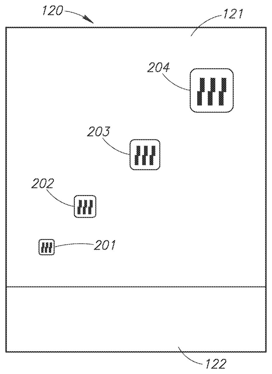
Referring toFIG. 1, a device100is shown that has a video camera110configured to monitor the distance between the device and a test subject's eyes. The device100also comprises a touch screen display120that is divided into a main game play area121and an ancillary area122. The play area121is used to display the visual action of a game. The play area121is preferably approximately square, but other shapes may also be used. The ancillary area122is used as an ancillary human-user input and score display, as discussed below.
Referring toFIG. 2, the device100may be positioned on a stand145such that the user's eye130is approximately equal distance (D) to the top and bottom of the device's display120. The camera110on the front of the device100is used to monitor ambient light. The test is preferably performed in dim room lighting (low scotopic). The brightness of the screen120may be automatically adjusted according to the ambient light level within an acceptable range. Outside of the acceptable range, a warning message on the screen120may be provided to instruct the user to increase or decrease the room lighting appropriately.
Referring toFIGS. 3A and 3B, an occluder160is shown that may be used to occlude vision in one eye so the other eye can be tested using the video game of the present invention. The occluder160could be mounted on spectacles150or could be fixed on the user's head using straps. The occluder160has a visible feature165of known dimensions which is captured by the video camera110and can be analyzed by a computer (seeFIG. 4) of the device100to monitor the distance between subject's eyes and the device. As shown, the visual feature165could include, for example, a horizontal bar165A with well-defined termination points (e.g., vertical bars165B and165C) so that the length of the horizontal bar may be easily determined by computerized automatic image processing. Other shapes or patterns, such as a circle or rectangle, could also be used. Based on the video analysis, the device100may display an instruction140on the screen120(and/or by sound) so the user can position his or her head within the optimal range of distance from the device.
An alternative method, shown inFIG. 3C, of obtaining the desired viewing distance D asks the user to adjust the viewing distance until the size of the real-time video display the occluder160has the correct size. In the example shown, the user compares the video display of the calibration feature165against a regularly spaced vertical line overlay141. The user moves his/her head and/or the device100back and forth until the length of the feature165(e.g., between vertical bars165B and165C) spans two interval spacing between the vertical lines141.
Another alternative method for the device100to monitor viewing distance is to analyze the size of the subject's eye (e.g., corneal width from limbus to limbus) being tested or other features on the subject's face. For this alternative to work, a video frame may first be taken when the user's face is at a known distance from the camera110. As an example, the distance could initially be established using a measuring tape or ruler with a known length.
Referring now toFIG. 4, an input device123and an output device120are shown connected to a computer166of the device100. The term computer used in this instance refers to processors, memory, data/control bus, etc., as opposed to the peripheral input and output devices. The input and output functions can both be performed on the same touch screen, as depicted inFIG. 1. The video camera110produces image frames that are processed by the computer166to monitor the distance between the subject's eyes and the device100. The subject produces action in the video game with the input device123and the game background and actions are displayed on the video display or output device120. The game sounds are output on a speaker125.
The test results may be transmitted or uploaded (e.g., wirelessly) to a server168over a network167(e.g., the Internet, a mobile communications network, etc.). This feature allows for the storage, tracking, review, and analysis of the test results over time to detect patterns, such as the deterioration of a patient's vision. The patient, his or her healthcare professionals, or others may access the data stored on the server168through a web browser or via a link to an electronic health record system of a healthcare facility. The test results data may be processed and presented in a manner that is useful for the patient and/or healthcare provider to analyze the results.
The server168may also be configured to provide notifications or alerts to the patient or their healthcare provider for any changes in vision that may require further attention or treatment. These alerts may be sent to a patient's and/or healthcare provider's electronic devices (e.g., the mobile phone169) via email, SMS messages, voice messages, or any other suitable messaging system. For example, if an analysis of the uploaded test results reveals that a patient's vision is deteriorating, the server168may automatically send a message to the patient and/or a healthcare provider to alert them of the change in condition. Thus, appropriate action or treatment may be provided.
Initial Setup
The user is instructed to perform the setup steps by the device100without the need of human professional instruction and supervision, though a human supervisor could be helpful to assure proper use.
The first time the subject is taking the test, the subject's identifying information (e.g., name, age, etc.) may be entered into the computer166using the user input interface123. An acuity map of a normal population may be used as the initial estimate of the subject's acuity map. For subsequent tests, the initial estimate may be the average of the subject's recent tests.
Since a game is used to perform the MAP test, the terms “game” and “test” are used interchangeably herein. Further, the user of the device100is the subject of the MAP test and the game player. Therefore, the terms “user,” “subject,” and “player” are also used interchangeably.
Before and/or during each game, the brightness of the screen120may be adjusted to the desired range by the use of the camera110(seeFIG. 1) as described above. If the ambient light detected by the camera110is too high or low to be compensated for by adjusting the brightness, a message may be displayed on the display area121so the user can adjust the light level in the room. The test should generally be administered with the light level in the low scotopic range.
The test is administered at a viewing distance that is sufficient to provide useful AMD diagnostic information. For example, the iPad 2® used in some embodiments has a screen that is 5.8 inches wide. Referring back toFIG. 1, the display area121uses this full width of the screen. This provides a maximum perimetry testing area of 18 degrees full width at a viewing distance of 18 inches, using the methods of the current invention. As discussed above, the device100monitors the viewing distance D by taking images of the user's face (seeFIG. 3) using the camera110. The computer166(seeFIG. 4) analyzes the visible feature165on the occluder160to compute the distance between the camera110and the occluder160, which is approximately the same as the viewing distance. At the setup of each game, the device100instructs the user to move his or her head into position so the image of their face (in particular, the occluder160) can be captured by the camera110and displayed in display area121. The device100then instructs the user to move closer to or further from the display area121to bring the user's eyes into the target range of viewing distance. The initial target range may be 17 to 19 inches, for example.
Generally, the user should be wearing spectacle correction for their best vision within the operating range of the viewing distance. For an emmetrope, a pair of reading glasses with power of +2.25 D would be optimal for the viewing distance of 18 inches. If spectacles are used, the occluder160should be mounted over the spectacle lens over the eye not being tested. If no spectacles are needed or if the subject is using contact lenses, the occluder160could be mounted over plano glasses or strapped on as an eye patch.
Game Playing and Perimetry Test Cycle
Many game scenarios could be devised based on the principles of the current invention. For the purpose of demonstration, an exemplary flash card multiple-choice game illustrated inFIGS. 5-20is described.
The initial rounds of the game are used to establish central visual acuity. This is done using several rounds of “open card” games. Referring toFIG. 5, the display area121has a uniform background (e.g., a green background) with a number of open cards201-204thereon displaying visual acuity targets over a range of sizes bracketing around the user's estimated central acuity. Vernier acuity targets are preferably used, though normal acuity targets can also be employed. Vernier acuity targets test relative displacements such as relative shifts between two groups of line segments, as shown by the cards201-204inFIG. 5. A single line can also be used instead of multiple lines. Other types of unevenness or distortions in a straight line, curve, or circle can also be used. In an opening round, the subject selects the smallest card201-204on which he (or she) can perceive the shift between line segments by tapping on the touch screen120with a finger210, as shown inFIG. 6. The visual angle subtended by the spatial shift defines the Vernier acuity.
The selected acuity level is then confirmed and refined using a multiple-choice test. Referring toFIG. 7, four open cards221-224each showing the same size target are displayed. The player is tasked to select the one card of the cards221-224that is different from the other cards. In this example, the card221has a lateral shift between the line segments, while the other three cards222-224have no shift (aligned). For the sake of brevity, cards with shifted line segments are referred to as “shifted” cards and card with the aligned line segments are referred to as “aligned” cards. The test asks the subject to pick out the one card that is different from the other cards. Thus, the test could involve one shifted card and several aligned cards, or one aligned card and several shifted cards. A greater or smaller numbers of cards (for example, 2, 3, or 9 cards) could also be used.
Referring toFIG. 8, the subject chooses the one of the card221-224he believes is different from the other cards by tapping on the card on the touch screen120with a finger225. In this example, the choice was wrong and therefore the device100displays the correct choice with a message226and displays a score227saying “0 correct out of 1 test.” If the subject cannot see the patterns on the card, then the subject should tap on a “cannot see” button228rather than tap on the wrong choice. This should be explained in the game instructions so the test may proceed faster. After a brief delay, a new round of the game is started with a display similar to that shown inFIG. 7, but with a new set of cards where the location and type (shifted versus aligned lines) of the correct choice is different (e.g., randomly selected, etc.). In some embodiments, the central acuity level is established when the player chooses a sufficient number of correct cards at a certain error level (e.g., a 5% error level—the probability of achieving equal or greater number of correct choices being less than 5%).
Given a choice of four cards each round and allowing for zero selection error, the subject needs to make the correct choice in three rounds of the game to establish that he was able to perceive the correct choice at the acuity level being displayed. If this occurs, then the acuity level is raised (i.e., the lateral shift is made smaller) and more rounds of games are played until the user's perception is established or refuted. If the player clicks the “cannot see” button228(seeFIG. 8) or makes the correct choice in only one of three rounds, then perception is refuted. If he make the correct choice in two of three rounds (a borderline case), then one additional round is played for a total of four rounds. If the player makes the correct choice in three of four rounds, then perception is established. If he made the correct choice in two of four rounds, then perception is refuted. Thus for a choice of four cards per round, three rounds are played if the player makes no error and four rounds are played if the player makes one error. For a choice of fewer cards, a larger number of rounds are needed. The numbers of test rounds needed are tabulated in Table 1 shown below.
TABLE 1The number of test rounds needed to establishperception at <5% error level.# of# allowed wrongchoices01258335434923
Table 1 is calculated based on the following equations on the condition that Py≦Y99% (PC<1%). Given 3 circle diameters, 8 sectors per circle, and 5 game rounds per location, the minimum number of rounds per game is 120. The 120 rounds are preferably randomly sequenced to avoid boredom. Since each game round only take a few seconds, the entire AMD screening test can be completed in a few minutes. More rounds are needed if metamorphopsia is detected as explained below.
TABLE 2The number of choices of the same kind needed to establisha metamorphopsia or scotoma at 5 and 1 percentile errorlevels. A probability of 1/8 for each choice is assumed.# of same choices# roundsPC< 5%PC99% certainty, that location is blocked out in future game rounds. Referring toFIG. 31, a block510is placed over the bottom sector location where metamorphopsia was located so the metamorphopsia can no longer be perceived. The arrow505to that sector location where metamorphopsia was located, as illustrated inFIG. 29, is also removed to disable that choice. The blocking is done separate for each of the 3 circle diameters: foveal, parafoveal, and perifoveal. After each new block is placed, the game for that wheel is reset to allow accurate scotoma and metamorphopsia detection in the remaining unblocked sectors.
Although the description above employs a distortion in a circle of dots as the hyperacuity target502the subject is asked to detect, other circular targets could be used. For example, the circle could be a continuously line and discrete or continuous distortion could be employed as the hyperacuity target. In another implementation, a gap in a continuous circle could serve as an ordinary acuity (not hyperacuity) target. In yet another implementation, a polygonal (e.g. octagon) is used and a missing side is the acuity feature the subject is asked to detect. A significant feature of the current invention is that the acuity or hyperacuity feature is presented on a symmetric target so that the target presentation does not cause the subject's gaze to deviate from the center.
Alternative Target Presentation Scheme
Since the hyperacuity target502is a circle around the central fixation target500, its presentation does not distract the subject's gaze. Therefore one can employ a smoothly expanding circular target. Referring toFIG. 32, the test cycle starts with finger tap504. A circular hyperacuity target512is initially small, and continuous without any distortion break. Again, it is centered on a central fixation dot or target511. The circle target512expands, as shown inFIG. 33. The subject is asked to tap directly on a break or distortion513in the expanded circle target512ofFIG. 33. Referring toFIG. 34, if the tap514is in the correct octant occupied by distortion513, then it suggests that the hyperacuity distortion target (distortion513) was successfully perceived by the subject. If the subject fails to tap within a time limit then the distortion was not perceived. If the user taps prematurely or on the wrong octant then a metamorphopsia is likely. These findings are confirmed by repeated rounds of testing as described above.
The advantage of this alternate scheme is that the user taps on the distortion513directly (seeFIG. 34) without going to a second screen of arrows (seeFIG. 30). Furthermore, circles of various sizes can be tested in quick succession. Thus the testing can proceed more rapidly. The limitation of this configuration is that the circle expansion and the presentation of the target must be slow relative to the subject's reaction time. The subject's reaction time must first be assessed using a superthreshold target (large distortion) that the subject is able to perceive.
A contracting circular target can also be used. An efficient implementation is a series of expanding and contracting circular targets that start at a randomly determined circle diameter. These random variation keep the test results from being skewed by player learning and expectation, and also keeps the game more interesting.
Assessment of Fixation Reliability
To test whether the subject is reliably fixing gaze on the central fixation target500/511, the subject is asked to tap on the central fixation target when it flashes. This task encourages the subject to keep gaze on the central fixation target. This is done intermittently between the hyperacuity testing cycles. The percentage of fixation failures is monitored to determine if the test results are reliable.
Keeping of Game Score
The subject is rewarded by game score increment for correctly tapping on the distortion during the hyperacuity testing cycle or tapping on the fixation target during fixation reliability testing cycles. The number of points awarded should be larger for faster reaction to encourage faster game play. The subject is punished by game score decrement when tapping at the wrong location or failing to tap. The score and the accompanying visual and sound feedback keep the player interested. The score is meant to be a player motivator and is generally not the same as the visual test results, though they may be partially related.
Dynamic Correction of Display Size
During the game play and acuity testing, the distance between the subject's eyes and the display area (screen) of the device100is continuously monitored so the size and location of the peripheral visual field stimulus remains true to the specified visual angles. Thus, if the subject's eyes move closer to the device the image on display will be made smaller and if the subject's eyes move away from the device then the image on display will be made larger.
Mapping of Scotoma and Metamorphopsia
The outputs of the game are a map of scotoma probability (FIG. 35) and a map of metamorphopsia probability (seeFIG. 36). The dimension of the maps is preferably approximately 16°, which can be easily accommodated by tablet computers currently on the market. For example, the iPad2 has a display area that is 5.8 inches wide. This provides a maximum visual field width of +/−18 degrees at a viewing distance of 18 inches. Referring toFIG. 35, the scotoma probability map600is presented as a polar grid of probability values. The polar grid is divided into central region612spanning the central 3° visual angle (diameter), parafoveal region613spanning the annulus from 3° to 8° visual angle (diameter), and perifoveal region614spanning the annulus from 8° to 16° visual angle (diameter). The parafoveal and perifoveal annuli are each subdivided into 8 sectors. Referring toFIG. 36, the metamorphopsia map700is similarly divided into 3 diameters712,713, and714. The probability levels are preferably displayed by easy to interpret symbols on the maps. InFIGS. 35 and 36, the unhatched circles represent 90% probability of abnormality, and the cross-hatched circles represent >99% probability of abnormality. More gradations or exact probability values could also be provided. The maps are preferably automatically computed by the game device computer immediately after the game so the results can be shown to the player to maintain interest in the game.
FIGS. 35 and 36represent one preferred implementation. More or fewer angular sectors or annuli could be employed. The map division shown is preferred because the number of test locations (24) is reasonable and the sampling density is appropriately weighed with denser central sampling.
Electronic Communication to a Physician
The results of the video game tests are preferably communicated to a physician on a regular basis and whenever a new abnormality is detected. Any abrupt or gradual trend in scotoma or metamorphopsia probability is automatically computed by the game device and communicated to the physician. Alternatively, test results can be tracked and analyzed over the long term by the central computer server168. Communication between the game device100, central server168, and physician occur over an electronic network167. The physician can instruct the subject to take the test more or less frequently via the same network. If the level of scotoma and/or metamorphopsia is too severe for the standard distortion magnitude (if a majority of the map sectors show abnormality), the physician can increase the magnitude of the vernier distortion so only areas with more severe scotoma and metamorephopsia are mapped. This improves the ability to detect further increase in abnormal areas.
Advantages
The current embodiment is a video game-based preferential hyperacuity perimetry test having one or more of the following advantages over prior art:1. The test can be implemented on common consumer-owned hardware platforms such as a smartphone, laptop computer or a tablet computer (i.e. the iPad2). This allows more frequent testing.2. The target has circular symmetry around the central fixation target, thereby minimizing the temptation for subject gaze to move off center.3. Fixation is further assured by a task that requires the user to tap on the central fixation target periodically.4. The game uses action-generated sound to help hold subject attention.5. The pace of the game is controlled by the player.6. The subject's head is free to move to improve comfort. The distance between the video screen and the subject's eyes is monitored by a camera and this information is used to provide compensatory adjustment in visual stimulus size so the visual angle subtended by the stimulus remains well characterized.7. The ambient light level is monitored by the video camera(s) included in the apparatus of the current embodiment.
The foregoing described embodiments depict different components contained within, or connected with, different other components. It is to be understood that such depicted architectures are merely exemplary, and that in fact many other architectures can be implemented which achieve the same functionality. In a conceptual sense, any arrangement of components to achieve the same functionality is effectively “associated” such that the desired functionality is achieved. Likewise, any two components so associated can also be viewed as being “operably connected”, or “operably coupled”, to each other to achieve the desired functionality.
While particular embodiments of the present invention have been shown and described, it will be obvious to those skilled in the art that, based upon the teachings herein, changes and modifications may be made without departing from this invention and its broader aspects and, therefore, the appended claims are to encompass within their scope all such changes and modifications as are within the true spirit and scope of this invention. Furthermore, it is to be understood that the invention is solely defined by the appended claims. It will be understood by those within the art that, in general, terms used herein, and especially in the appended claims (e.g., bodies of the appended claims) are generally intended as “open” terms (e.g., the term “including” should be interpreted as “including but not limited to,” the term “having” should be interpreted as “having at least,” the term “includes” should be interpreted as “includes but is not limited to,” etc.).
It will be further understood by those within the art that if a specific number of an introduced claim recitation is intended, such an intent will be explicitly recited in the claim, and in the absence of such recitation no such intent is present. For example, as an aid to understanding, the following appended claims may contain usage of the introductory phrases “at least one” and “one or more” to introduce claim recitations. However, the use of such phrases should not be construed to imply that the introduction of a claim recitation by the indefinite articles “a” or “an” limits any particular claim containing such introduced claim recitation to inventions containing only one such recitation, even when the same claim includes the introductory phrases “one or more” or “at least one” and indefinite articles such as “a” or “an” (e.g., “a” and/or “an” should typically be interpreted to mean “at least one” or “one or more”); the same holds true for the use of definite articles used to introduce claim recitations. In addition, even if a specific number of an introduced claim recitation is explicitly recited, those skilled in the art will recognize that such recitation should typically be interpreted to mean at least the recited number (e.g., the bare recitation of “two recitations,” without other modifiers, typically means at least two recitations, or two or more recitations).
Accordingly, the invention is not limited except as by the appended claims.
Claims
- A computer-implemented method for testing macular visual acuity, comprising: (A) displaying a fixation location indicator on a display of a computing device configured for fixation thereon by a user;(B) simultaneously and briefly displaying on the display a hyperacuity target arranged around the fixation location indicator, wherein a correct portion of the hyperacuity target is spaced apart from the fixation location indicator at a different distance than an other portion of the hyperacuity target;(C) receiving input from the user via a user input device indicating a user selection of a portion of the hyperacuity target;(D) determining whether the user selected the correct portion;and (E) recording whether the user selected the correct portion in a data storage.
- The computer-implemented method of claim 1 , wherein the correct portion is spaced farther from the fixation location indicator than the other portion of the hyperacuity target.
- The computer-implemented method of claim 1 , wherein the hyperacuity target has a symmetrical shape.
- The computer-implemented method of claim 1 , wherein the hyperacuity target comprises a plurality of targets and the correct portion is one of the plurality of targets.
- The computer-implemented method of claim 1 , wherein the hyperacuity target includes a substantially continuous shape surrounding the fixation location indicator and the correct portion is a distorted or discontinuous portion of the substantially continuous shape.
- The computer-implemented method of claim 1 , wherein the input from the user includes tapping on one of a plurality of arrows displayed on the display.
- The computer-implemented method of claim 1 , the method further comprising: testing visual acuity by executing a plurality of visual acuity rounds of the video game, each visual acuity round comprising steps (A)-(E);and generating a visual acuity map based on a user's selections during the plurality of visual acuity rounds, wherein in the visual acuity map is divided into a plurality of locations, and each of the plurality of locations is tested by at least one visual acuity round of the video game.
- The computer-implemented method of claim 7 , the method further comprising: obscuring part of the hyperacuity target based on the user selection in at least one of the plurality of visual acuity rounds.
- The computer-implemented method of claim 7 , wherein a size of the hyperacuity target displayed on the display is different in at least two of the plurality of visual acuity rounds.
- The computer-implemented method of claim 7 , wherein, during each of the visual acuity rounds, a characteristic of the hyperacuity target displayed on the display is dependent on the user's selection in a previous visual acuity round.
- The computer-implemented method of claim 7 , wherein the generating a visual acuity map includes generating a scotoma probability map or a metamorphosis probability map.
- The computer-implemented method of claim 7 , wherein a size of the hyperacuity target is either successively expanded or contracted in subsequent visual acuity rounds.
- The computer-implemented method of claim 1 , wherein a size of the hyperacuity target displayed on the display is dependent on an area of visual acuity being tested.
- The computer-implemented method of claim 1 , wherein the input from the user includes tapping on the hyperacuity target displayed on the display.
- The computer-implemented method of claim 1 , further comprising: providing an instruction to the user to either increase or decrease his or her distance from the display based on a distance between the display of the computing device and the user.
- The computer-implemented method of claim 1 , further comprising: adjusting a brightness level of the display dependent on an ambient light level.
- The computer-implemented method of claim 1 , further comprising: transmitting data relating to the user's visual acuity to an external computing device.
- The computer-implemented method of claim 1 , wherein determining whether the user selected the correct portion includes determining (I) a visual acuity score based on whether the user selected the correct portion;and (II) a game score based on a reaction time between when the hyperacuity target is displayed and when the input from the user is received.
- A system for testing macular visual acuity, comprising: a display;a user input device;and a computer coupled to the display and the user input device, and configured to (A) display a fixation location indicator on the display, (B) simultaneously and briefly display on the display an hyperacuity target arranged around the fixation location indicator, wherein a correct portion of the hyperacuity target is spaced apart from the fixation location indicator at a different distance than an other portion of the hyperacuity target, (C) receive input from the user via the user input device indicating a user selection of a portion of the hyperacuity target, and (D) determine whether the user selected the correct portion.
- The system of claim 19 , wherein the correct portion is spaced farther from the fixation location indicator than the other portion of the hyperacuity target.
- The system of claim 19 , wherein the hyperacuity target has a symmetrical shape.
- The system of claim 19 , wherein the computer is further configured to (E) record whether the user selected the correct portion in a data storage.
- The system of claim 22 , wherein the computer is further configured to: execute a plurality of visual acuity rounds of the video game, each visual acuity round comprising steps (A)-(E);and generate a visual acuity map based on the user's selections during the plurality of visual acuity rounds, wherein in the visual acuity map is divided into a plurality of locations, and each of the plurality of locations is tested by at least one visual acuity round of the video game.
- The system of claim 23 , wherein, when generating the visual acuity map, the computer is configured to generate a scotoma probability map or a metamorphosis probability map.
- A non-transitory computer-readable medium encoded with computer executable instructions, which when executed by a processor, causes the processor to perform a method comprising: (A) displaying a fixation location indicator on a display of a computing device configured for fixation thereon by a user;(B) simultaneously and briefly displaying on the display an hyperacuity target arranged around the fixation location indicator, wherein a correct portion of the hyperacuity target is spaced apart from the fixation location indicator at a different distance than an other portion of the hyperacuity target;(C) receiving input from the user via a user input device of the computing device indicating a user selection of a portion of the hyperacuity target;(D) determining whether the user correctly selected the correct portion;and (E) assessing the user's visual acuity based on the selection of the user.
- The non-transitory computer-readable medium of claim 25 , wherein, in the simultaneously and briefly displaying, the correct portion is spaced farther from the fixation location indicator than the other portion of the hyperacuity target.
- The non-transitory computer-readable medium of claim 25 , wherein, in the simultaneously and briefly displaying, the hyperacuity target has a symmetrical shape.
- The non-transitory computer-readable medium of claim 25 , wherein, in the simultaneously and briefly displaying, the hyperacuity target comprises a plurality of targets and the correct portion is one of the plurality of targets.
- The non-transitory computer-readable medium of claim 25 , wherein, in the simultaneously and briefly displaying, the hyperacuity target includes a substantially continuous shape surrounding the fixation location indicator and the correct portion is a distorted or discontinuous portion of the substantially continuous shape.
- The non-transitory computer-readable medium of claim 25 , the method further comprising: testing visual acuity by executing a plurality of visual acuity rounds of the video game, each visual acuity round comprising steps (A)-(E);and generating a visual acuity map based on the user's selections during the plurality of visual acuity rounds, wherein in the visual acuity map is divided into a plurality of locations, and each of the plurality of locations is tested by at least one visual acuity round of the video game.
- The non-transitory computer-readable medium of claim 30 , wherein the generating a visual acuity map includes generating a scotoma probability map or a metamorphosis probability map.
- The non-transitory computer-readable medium of claim 25 , wherein determining whether the user selected the correct portion includes determining (I) a visual acuity score based on whether the user selected the correct portion;and (II) a game score based on a reaction time between when the hyperacuity target is displayed and when the input from the user is received.
- A method of distributing data adapted to be stored on a non-transitory computer-readable medium, the data including computer executable instructions, which when executed by a processor, cause the processor to perform a method for testing macular visual acuity comprising the steps of: (A) displaying a fixation location indicator on a display of a computing device configured for fixation thereon by a user;(B) simultaneously and briefly displaying on the display a hyperacuity target arranged around the fixation location indicator, wherein a correct portion of the hyperacuity target is spaced apart from the fixation location indicator at a different distance than an other portion of the hyperacuity target;(C) receiving input from the user via a user input device indicating a user selection of a portion of the hyperacuity target;(D) determining whether the user selected the correct portion;and (E) recording whether the user selected the correct portion in a data storage.
- The method of distributing data of claim 33 , wherein, in the simultaneously and briefly displaying, the correct portion is spaced farther from the fixation location indicator than the other portion of the hyperacuity target.
- The method of distributing data of claim 33 , wherein, in the simultaneously and briefly displaying, the hyperacuity target has a symmetrical shape.
- The method of distributing data of claim 33 , the method for testing macular visual acuity further comprising: testing visual acuity by executing a plurality of visual acuity rounds of the video game, each visual acuity round comprising steps (A)-(E);and generating a visual acuity map based on the user's selections during the plurality of visual acuity rounds, wherein in the visual acuity map is divided into a plurality of locations, and each of the plurality of locations is tested by at least one visual acuity round of the video game.
Disclaimer: Data collected from the USPTO and may be malformed, incomplete, and/or otherwise inaccurate.