U.S. Pat. No. 9,427,664
HIGHLY INTERACTIVE ONLINE MULTIPLAYER VIDEO GAMES
AssigneeSUGARCANE DEVELOPMENT, INC.
Issue DateMay 4, 2015
Illustrative Figure
Abstract
Latency compensation is performed during play of a multiplayer video game over a network. A first system includes a first estimator, a first player, and a first game object controlled by movement of the first player, and a second system includes at least a second player and a second game object controlled by movement of the second player. The first estimator receives data values characterizing delayed states of the second system via the network. Based on the received data values, the first estimator estimates a latency-compensated state of the second game object using a physics model of the second game object and a behavior model of the second player. The behavior model provides a representation of how the second player interacts with the video game relative to the first player. The first player is enabled to interact with the video game with compensated latency.
Description
DESCRIPTION OF EMBODIMENTS In the following description, numerous specific details are set forth. However, it is understood that embodiments of the invention may be practiced without these specific details. In other instances, well-known circuits, structures and techniques have not been shown in detail in order not to obscure the understanding of this description. It will be appreciated, however, by one skilled in the art, that the invention may be practiced without such specific details. Those of ordinary skill in the art, with the included descriptions, will be able to implement appropriate functionality without undue experimentation. Embodiments of the invention provide a method, system and apparatus for restoring the quality of game play in the presence of latency and data loss in online multiplayer video games (also referred to as “multiplayer games”). The method, system and apparatus implement a latency compensation mechanism that enables players to engage in a highly-interactive video game over a network. The latency compensation mechanism enables a user's system (also referred to as a “self player's system”) to estimate the current states (also referred to as “latency-compensated states”) of its peer player's system based on the delayed states sent from the peer player's system. The latency compensation mechanism described herein exploits feedback structures of multiplayer games. Behavior models of human actions are generated for estimating the states in the feedback systems. State estimation is performed using the behavior models and physics models of game objects. The behavior model of a human peer player (also referred to as a “player model of a peer player” or a “peer player model”) is used by an estimator in a self player's system. The peer player model is specific to the peer player and is also specific to the self player that plays against the peer player. The peer player model ...
DESCRIPTION OF EMBODIMENTS
In the following description, numerous specific details are set forth. However, it is understood that embodiments of the invention may be practiced without these specific details. In other instances, well-known circuits, structures and techniques have not been shown in detail in order not to obscure the understanding of this description. It will be appreciated, however, by one skilled in the art, that the invention may be practiced without such specific details. Those of ordinary skill in the art, with the included descriptions, will be able to implement appropriate functionality without undue experimentation.
Embodiments of the invention provide a method, system and apparatus for restoring the quality of game play in the presence of latency and data loss in online multiplayer video games (also referred to as “multiplayer games”). The method, system and apparatus implement a latency compensation mechanism that enables players to engage in a highly-interactive video game over a network. The latency compensation mechanism enables a user's system (also referred to as a “self player's system”) to estimate the current states (also referred to as “latency-compensated states”) of its peer player's system based on the delayed states sent from the peer player's system.
The latency compensation mechanism described herein exploits feedback structures of multiplayer games. Behavior models of human actions are generated for estimating the states in the feedback systems. State estimation is performed using the behavior models and physics models of game objects. The behavior model of a human peer player (also referred to as a “player model of a peer player” or a “peer player model”) is used by an estimator in a self player's system. The peer player model is specific to the peer player and is also specific to the self player that plays against the peer player. The peer player model is continuously refined during real-time game play based on game play data. In one embodiment, the peer player model may also be objective-specific with respect to a distinct play objective in the game. As used herein, a game object is a simulated object in the game that is governed by game physics and player actions. It is graphically rendered on a game display. For example, a car is a game object in a car racing game, and a tennis player is a game object in a tennis game.
FIG. 1illustrates a network architecture in which embodiments of the invention may operate. In one embodiment, player-1 and its game device110interact with player-2 and its game device120via a network130, which may be any combination of local area and/or wide area networks (e.g., the Internet), using wired and/or wireless communication systems. The game devices110and120exchange time-stamped data over the network130during real-time game play. Additionally, the game devices110and120also exchange data with a server140(also referred to as a “game server”) over the network130. In one embodiment, the data exchange with the server140may take place at the start and end of a game; e.g., when the game devices: register with the server, receive stored player models from the server, send refined player models to the server, time synchronize with the server at game start, receive updates to game software, etc. In one embodiment, the game devices110and120also send game states to the server140during game play for real-time and/or offline analysis. The server140may serve as a time server. The server140may include one or more server computers. In one embodiment, the game devices110and120perform the functions of the server140.
In an alternative embodiment, the game devices110and120may exchange data during real-time game play over another network135, which may be any combination of local area and/or wide area networks (e.g., the Internet), using wired and/or wireless communication systems. The network135can be different and/or separate from the network130to which the server140is connected. For example, the network135may be a local area network and the network130may be a wide area network. As another example, the network135may be a wireless network and the network130may be a combination of wired and wireless communication systems.
Although only two players are shown and described, it is appreciated that more than two players can participate in the same game play. The multiple players may be located anywhere in the world where network connections are available. Some of the players may be co-located in the same area and communicate via a local area network; some of the players may be located in geographically diverse areas and communicate via a wide-area network.
FIG. 2Aillustrates an environment in which an embodiment of the invention may operate. In this embodiment, player-1 and player-2 are human players engaged in a multiplayer video game. Player-1 and player-2 interact via respective game controls210A-B, respective game consoles211A-B, respective displays212A-B, and a network connection213. The communications between the game controls210A-B, the game consoles211A-B, the game displays212A-B, and the network connection213may be any combination of wired and wireless connections. The game controls210A-B may include remote controllers, joysticks, keypads, buttons, sensors, etc., for player-1 and player-2 to control game objects displayed on the displays212A-B. The game display212A-B may be a TV screen, a computer display, a projector, or a graphical user interface on any electronic device.
In some embodiments, a player's game control, game console and/or game display may be integrated into one or two devices. A player controls his game object by his movement. In some embodiments, a player may control his game object by moving a control device (e.g., a joystick, a push button, a keypad, etc.). Alternatively, a player may control his game object through a sensor (e.g., an accelerometer, a gyroscope, a light sensor, a camera, etc.) by body movement without physically moving a device or components of a device (e.g., without moving a joystick, pressing a button or other game controls, etc.). Player action (also referred to as “player motion” or “player input”) is read by the game device through a sensor or a control device. In some embodiments, players that are co-located in the same area (e.g., in the same room) may share the same game display and/or game console.
FIG. 2Billustrates an environment in which another embodiment of the invention may operate. In this embodiment, player-1 and player-2 are engaged in a multiplayer game using respective mobile devices215A-B via a network connection216. The mobile device215A-B may be a special-purpose, multi-purpose, or general-purpose mobile device having access to a network connection for interactive online video game play. The mobile device215A-B includes one or more built-in sensors to detect its user's movement, and an integrated display to show the game objects and the surrounding game world to its user. An embodiment of the mobile device215A-B is described later with reference toFIG. 11B.
Thus, the term “game device” hereinafter refers to a wide range of electronic devices. A game device may be a single device that has integrated control, console and/or display. A game device may alternatively be multiple separate devices that are connected by wired/wireless connection for detecting players' movements, controlling the game objects and displaying the games. A game device may be a mobile device or a stationary device, a special-purpose, multi-purpose, or general-purpose device, a wired device or a wireless device.
FIGS. 2A and 2Balso illustrate the multiple sources of latency between player-1's action and player-2's reaction, as shown with dotted lines223,224and226,227. For example, dotted line223shows the latency that includes: the time it takes for detecting player-1's movement, computation of the game states based on the movement, network delays, displaying the updated game states on player-2's display, and the reaction time of player-2. The latency can be in the range of several hundred milliseconds and can be time-varying. The dotted lines223and224in combination show a close-loop feedback structure inFIG. 2A, and the dotted lines226and227in combination show a close-loop feedback structure inFIG. 2B.
The latency compensation mechanism models the following components in the close-loop feedback structures: (1) player's actions in response to what the player sees or hears on the game display or speaker, (2) effect of player's actions on physics of the game object's model, and on what is sent across the network to other player's game devices and server, (3) displaying or creating sounds based upon physics variables, networked delayed values of other game states, predictions, server supplied values and actions of local players and network delayed actions of players, and (4) delays due to computations, display, sensor processing on game controllers and game.
An example of a car racing game is described below to illustrate the latency compensation mechanism. In real-world racing sport events such as Daytona NASCAR® race, the player strategies involve drafting to gain speed advantage over rivals. Drafting involves two or more drivers maintaining a single file, maintaining constant short relative distances between the cars. The drafting configuration provides speed advantage and is a key factor for winning the game. Interactions between the cars change the relative distance between the cars, which in turn change the drag experienced by the cars. When two cars, each controlled by a player, are engaged in drafting, there is continuous force interaction between the two cars due to changing drag experienced by the cars. This continuous interaction makes this play sensitive to latency. Thus, drafting is an example of a play objective in a car racing game. In a car racing game, there are many different types of plays other than drafting, such as slingshot around a car in front, bump drafting and pushing a rival off track. Some of these plays involve coordinated action among team members, and some of these plays involve proactive or reactive action to rival players. In the following description, cars are used as an example of game objects, and drafting, bump drafting, and slingshots are used as examples of play objectives. It is appreciated that the multiplayer games described herein can be any types of games having any types of game objects and any types of play objectives.
FIG. 3is a diagram illustrating a simplified representation of the feedback structures of two systems310and320that model a multiplayer game play without latency, according to one embodiment of the invention. To simplify the discussion, it is assumed that player-1 controls car-1 and player-2 controls car-2, where car-1 and car-2 are examples of game objects. The system310includes player-1 and car-1, and the system320includes player-2 and car-2. In one embodiment, player-1 and player-2 are both human players. A close-loop feedback path goes through both players: where player-1 controls car-1, the output of car-1 is fed back to player-2, player-2 controls car-2, and the output of car-2 is fed back to player-1. Similarly, another close-loop feedback path goes through both players starting and ending at player-2. The latency-free feedback ofFIG. 3assumes that the latency of sending data between game devices is zero or negligible. Negligible latency can be accomplished during offline design, which is the design and development activity during development of the game. Solo game (between a human player and an AI player) has no latency because the game is played with an AI on a game device. Multiplayer game with no latency can be created during game development by feeding player inputs from game devices to a single game physics simulation, and then sending the game physics output to the game devices for display. Thus, during game development, the latency of sending data between game devices can be made negligible.
In the example ofFIG. 3, player-1 output is the player motion m1tmeasured by its game device sensors at time t. Car-1 physics uses the measured player motion m1tto change throttle, steer and braking variables for computing car-1 states c1t. Car-2 states c2tat time t also enter car-1 physics because of contact forces and drafting drag. The input to each player include physics states of both cars, c1tand c2t. In a drafting play, each player maintains its controlled car at the drafting sweet spot for maximum speed advantage while staying on the track. This coordinated action requires the players to pay attention to the states of both cars.
FIG. 4is a diagram illustrating a representation of the feedback structures in a multiplayer game play with latency and latency compensation, according to one embodiment of the invention. One objective of latency compensation is to mitigate the effects of latency so that the closed-loop behavior is restored back close to the closed-loop behavior without latency ofFIG. 3. An empirical measure of closeness of the two closed-loop systems is to compare achieved game scores of players. Other measures such as closed-loop frequency responses and transient closed-loop simulations can also be used.
The system ofFIG. 4includes a player-1 system410and a player-2 system420. To player-1, the player-1 system410is the “self system” and the player-2 system420is the “peer system.” To player-2, the player-2 system420is the “self system” and the player-1 system410is the “peer system.” Player-1 and player-2 inFIG. 4represent real players (not their models). The player-1 system410generates car-1 states, player-1 motion and estimated car-2 states, and sends these as its “system states” to the player-2 system420. With the latency τ1introduced by network-1, the player-2 system420receives the delayed player-1 system states
(c1t-τ1,m1t-τ1,c^^2t-τ1).
Similarly, the player-2 system420generates car-2 states, player-2 motion and estimated car-1 states, and sends these states as its “system states” to the player-1 system410. With the latency τ2introduced by network-2, the player-1 system410receives the delayed player-2 system states
(c2t-τ2,m2t-τ2,c^^1t-τ2).
The player-1 system410includes a first estimator415(Est-1) and the player-2 system420includes a second estimator425(Est-2). Each of Est-1and Est-2is referred to as an estimator or a state estimator. Each of Est-1and Est-2can be designed and implemented according to a signal model500, as shown inFIG. 5according to one embodiment. The signal model500is an approximate model of the system whose states are being estimated. The signal model500used in the design of the estimator is in the feedback form. Referring toFIG. 5, the signal model500includes a player model510(which models the behaviors of the peer player), an object model520(e.g., a car model of the peer player's car), a network model530(which models the peer player's network), and an estimator model540(which models the estimator used by the peer system to estimate the self system state). Specifically, the signal model used in EST-1ofFIG. 4represents the player-2 system420in a simplified form, and the signal model used in EST-2ofFIG. 4represents the player-1 system410in a simplified form. The signal model simplification is described below where details of the estimator model540are provided.
The signal model500receives delayed states as measurements from the peer system, and generates estimated current states (“latency compensated states”) of the peer system based on the measurements. In one embodiment, only some of the delayed physics states (e.g., car positions and orientations) are sent over the network to reduce traffic, provided that the estimator using the signal model500can accurately reconstruct the states from the available measurements.
In the signal model500, the network model530describes time-varying delays and packet drops of the network that connects the two players' systems. In embodiments where time clocks on the two game devices are synchronized, time-stamped packets provide instantaneous per-packet delay measurements. Time clocks can be synchronized using protocols such as Network Time Protocol (NTP), Precision Time Protocol (PTP), or other standard network protocols for clock synchronization between computer systems over packet-switched, variable-latency data networks.
The player model510is the behavior model of the peer player. The player model510is a dynamic model. The player model510is represented by a non-homogenous differential equation
ⅆmxtⅆt=fplayer(mxt,mut,t)
or a difference equation mxt+1=Fplayer(mxt, mut, t). That is, the player model510has dynamic states mxtthat depend upon the time history of inputs mutto the model510and initial values of the states mxt=0. Player model output motion is a function of dynamic states mt=hplayer(mxt). The player model510may be a nonlinear model. Some input components may represent random processes. In some embodiments, the player model510may incorporate sub-models with states that take discrete values. Hidden Markov models and Bayesian Networks are an example of such models. In one embodiment, display delays are part of the player model510.
The object model520is the model of the game object controlled by the peer player. The object model520is a dynamic model. Similar to the player model510, the input-output relationship for the object model520(e.g., a car model) is represented by a non-homogenous differential equation
ⅆctⅆt=fobj(ct,cut,t)
or a difference equation ct+1=Fobj(ct, cut, t). That is, the object model520has dynamic states ctthat depend upon the time history of inputs cutto the object model520and initial values of the states ct=0. The object model520may also be a nonlinear model. Its output may not be all the dynamic states ctbut be a function of ctand inputs.
Typically, the physics of the object model520is completely known to the game developer at game development time and is described by a computer program as part of the game software. The dynamic states of the object model520can be measured by the self system during game play. The player model510, on the other hand, is not known at game development time. Its dynamic states are also not measured; only its inputs and outputs are available.
The player model510is player-specific; that is, it is specifically modeled according to the game playing characteristics of the peer player. As a peer player's skill improves over time, its player model510can be tuned during the game play to match the skill changes of the peer player. The player model510of the peer player is also specific to the self player who plays against the peer player. That is, the player model510not only captures the characteristics of the peer player but also the interaction between the self player and the peer player in a game play. Further details of the player model510will be described later with reference toFIG. 9.
The estimator model540models the estimator of the peer system. That is, the estimator model540within Est-1(FIG. 4) models Est-2, while the estimator model540within Est-2(FIG. 4) models Est-1. Referring again toFIG. 4, Est-1estimates states c2tof the car-2 model using delayed values received from the player-2 system420up to
c2t-τ2,m2t-τ2,c^^1t-τ2.
The estimated car-2 states output by Est-1is
c^^2t=E{c2t|c2t-τ2,m2t-τ2,c^^1t-τ2,…}.
Similarly, Est-2estimates states c1tof the car-1 model using delayed values received from the player-1 system410up to
c1t-τ1,m1t-τ1,c^^2t-τ1.
The estimated car-1 states output by Est-2is:
c^^1t=E{c1t|c1t-τ1,m1t-τ1,c^^2t-τ1,…}
Because each estimator uses the signal model500of its peer system, which in turn needs the state estimator in the self system, there is a recursive definition. In one embodiment, this impasse is overcome by replacing the estimator used by the peer with a simplified estimator model. One such simplification is to replace the estimator by an additive noise model. Thus, Est-2may include a simplified estimator model for estimating the output of Est-1{circumflex over (ĉ)}2t=c2twnt, wherein wnt, is the white noise. For Est-2, c2tis a locally known input. Similarly, Est-1includes an estimator model for estimating the output of Est-2: {circumflex over (ĉ)}1t=c1t+wnt. For Est-1, c1tis a locally known input.
Another simplification of the estimator model540uses a process driven by only white noise, where {circumflex over (ĉ)}2t+1={circumflex over (ĉ)}2t+dc2t, and dc2t+1=dc2t+wnt.
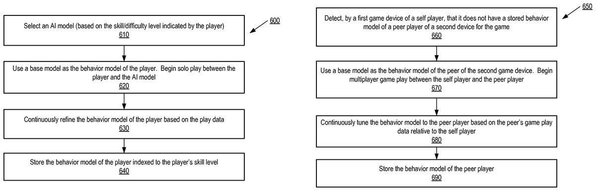
FIG. 6Ais a flow diagram of a method600for creating and tuning a player-specific player model (e.g., the player model510ofFIG. 5) based on solo play data, according to one embodiment of the invention. The term “solo play” herein refers to a game between a human player (player) and an Artificial Intelligence (AI) model. The method600may be performed during an offline development of the game; e.g., when developing player models of different skill levels for the game. The method600may be performed by the game device of the player, such as the game device1110ofFIG. 11B.
The method600starts with the game device selecting an AI model to play against the player (610). In one embodiment, the AI model may be selected based on the player's skill level or a difficulty level selected or indicated by the player. If neither a skill level nor a difficulty level is indicated, a default AI model may be selected. In one embodiment, the AI models may be indexed by psycho-motor feedback properties and skill levels, and may be stored on the game device or obtained by the game device from a server. An AI model can provide constant challenge to the player. An AI model also helps the game device to obtain player data in feedback, i.e., the excitations and the operating regions needed to rapidly identify or construct an appropriate player model for the player. The player model may be constructed by estimating model parameters and structure.
After the AI model is selected, the game device begins solo play between the player and the AI model, and identifies the behavior model of the player based on play data during the sole play (620). During the solo play, the game device also continuously refines the behavior model of the player based on the solo play data (630). The game device tunes the behavior model to the player as his skill improves. Alternatively or additionally, the behavior model of the player may be tuned by a server, such as the server140ofFIG. 1. For example, the game device may send the play data to the server which tunes the player model as the game is played. Based on the solo play data, the player's skill level is also identified. At the end of the game, the game device stores the behavior model of the player, where the behavior model is indexed to the player's skill level (640). The game device may store the player model in its data storage such as the memory. Alternatively or additionally, the behavior model of the player may be stored in the data storage of a server computer that hosts or manages the game, such as the server140ofFIG. 1, and/or another data storage location accessible by the server computer.
Player models developed during a solo play are to be used as a starting point during a multiplayer game play. A self player's behavior model is to be used by his peer player during live multiplayer game play. As described above with reference toFIG. 5, the behavior model of a self player is used by the estimator of the peer player's game device as an element of the signal model in feedback form.
FIG. 6Bis a flow diagram of a method650for creating and tuning a player model (e.g., the player model510ofFIG. 5) based on game play data between at least two human players (a self player and a peer player) according to one embodiment of the invention. The method650may be performed by the game device (first game device) of the self player who plays against a second game device of the peer player, such as the game device1110ofFIG. 11B.
The method650starts with the first game device detects that the device does not have a stored behavior model for the peer player of the second game device for the game (660). The first game device uses a pre-built base (nominal) model as the behavior model of the peer player; e.g., a base model that is selected based upon a known skill level of the peer player, and is selected from stored player models that are indexed to skill levels as described inFIG. 6A. The first game device then begins game play between the self player and the peer player (670). During the game play, the first game device continuously refines and tunes the behavior model to the peer player model based on the game play data of the peer player relative to the self player (680). At the end of the game, the first game device may store the behavior model of the peer player in its data storage such as the memory (690). Alternatively or additionally, the behavior model of the peer player may be stored in the data storage of a server computer that hosts or manages the game, such as the server140ofFIG. 1, and/or another data storage location accessible by the server computer.
During the solo play ofFIG. 6Aand the multiplayer game play ofFIG. 6B, the player may engage in a sequence of play actions for achieving a play objective that changes from time to time. For example, a self player of a car racing game may engage in starting the car, followed by drafting, bump drafting, and then slingshot. Each of the starting, drafting, bump drafting, and slingshot is a distinct play objective. In one embodiment, during solo play in the offline development of the game, the self player may perform a distinct maneuver to achieve each of the distinct play objectives to adapt the self player's model to the different play objectives. In one embodiment, the behavior model of a self player that is constructed or refined by the methods600and650includes multiple sub-models, each sub-model being specific to a different play objective. After the behavior model is created and stored, the behavior model is made available to other players who play against the self player.
FIG. 7is a flow diagram of a method700of latency compensation for a multiplayer game using a self-player-specific, peer-player-specific, and objective-specific player model, according to one embodiment of the invention. The method700may be performed by the game device of a self player, such as the game device1110ofFIG. 11B.
The method700begins with the game device of a self player starting the multiplayer game (710). In one embodiment, the game device executes operations for starting up the game by establishing network connectivity to a peer game device and a game server, and by obtaining a behavior model of the peer player. Clock synchronization is established between peer game devices and with game server (720). The game device of the player then obtains self system states and exchanges system states with the peer game device (730). Further details of the operation (730) will be described below with reference toFIG. 8A. The game device also obtains reference trajectories for the current play objective (740). Further details of the operation (740) will be described below with reference toFIG. 8B. The game device estimates the states of the peer system and refines the player model of the peer player during real-time game play (750). The game device further updates self states in game physics using estimated peer states, self states and sensor inputs (760). Based on the states of the self system and the estimated states of the peer system, the game device renders the graphics of the game world on the display of the game device (770). The game device may additionally generate sounds or other effects of the game. The game device then waits for the next simulation time frame (780), upon which the operations of blocks730-780are repeated.
FIG. 8Ais a flow diagram illustrating a method800of exchanging system states between a self system and a peer system, according to one embodiment of the invention. The method800provides further details of the operation (730) ofFIG. 7. The method800may be performed in the background; e.g., in parallel with the operations of730-780, by the game device of the self player such as the game device1110ofFIG. 11B.
The method800begins with the sensor of the self player's game device detecting the self player action and the game device attaching detected player action with a time stamp (810). The game device of the player reads received time-stamped data in the network buffers from the peer system (820). The time-stamped data describes the delayed system states of the peer system. The game device of the self player also sends time-stamped current system states to the peer system (830). The current system states include sensor read, inputs to the self player (such as the position and orientation of the car controlled by the self player), and other states of the game objects and the self player. All data are time-stamped. The network sends and receives are non-blocking asynchronous. The method800repeats throughout the process of game play.
FIG. 8Bis a flow diagram illustrating a method850of determining current play objective, according to one embodiment of the invention. The method850provides further details of the operation (740) ofFIG. 7. The method850may be performed in the background; e.g., in parallel with the operations of730-780, by the game device of the self player such as the game device1110ofFIG. 11B.
The method850begins with the game device of the self player detecting a change in the play objective based on self and peer system states (860). In one embodiment, change in play objective is inferred by a deviation of game object states from the reference value by an amount exceeding a threshold value. In an alternative embodiment, a change is detected when the prediction error between measurement and prediction for the self or peer system exceeds a threshold value in the state estimator. State estimators corresponding to the current play objective and other possible play objectives can be run in parallel. Upon detecting the change, the game device switches from one (first) sub-model to another (second) sub-model of the peer player's behavior model, where the first sub-model represents the old play objective and the second sub-model represents the new play objective (870), which is corresponding to a lower value of prediction errors at this time. This second sub-model of the peer player is specific to the new play objective and the peer player, and is used for the subsequent state estimation. The method850repeats throughout the process of game play.
The above description explains the operations of multiplayer game play performed by a game device. The description that follows provides further details of the player model510and the state estimation performed by the estimator using the signal model500ofFIG. 5.
FIG. 9illustrates a player model (such as the player model510ofFIG. 5), according to one embodiment of the invention. The player model510is used by the estimator1000(ofFIG. 10) to estimate the states of the peer player. The player model510includes a reference generator910, a disturbance generator920and a motion generator930, each of which is coupled to an adaptation module940that automatically tunes the player model520during real-time game play to the behavior of the peer player. The reference generator910generates reference trajectories re ft, the disturbance generator920generates a process noise dt, and the motion generator930generates an estimated player motion mt. For a car racing game, the input to the player model510includes the states of both cars, c1t, c2t, and adaptation input; the output is player motion mtof the peer player.
The motion generator930is the core of the player model510for generating estimated player motion. The motion generator930receives dt, re ft, c1, c2as input and generates player motion mtas output. The motion generator930models player behavior in a game play, which is a projection of real-life psycho-motor and cognitive behaviors of humans. The psycho-motor behavior acts at time scale of tens of milliseconds (e.g., 40 ms) to a few seconds, but has limited resources (e.g., memory). The cognitive behavior acts at a longer time scale, but is deliberative, associative and highly resourceful. The two behaviors act in concert to form the player model510. The model of psycho-motor behavior is typically described by continuous dynamical equations acting together in feedback within a continuous physical dynamical system. The model of psycho-motor behavior adapts to the environment and refines with skill improvements. Stochastic processes accounting of uncertainties are also needed to effectively model the psycho-motor behavior. On the other hand, the model of cognitive behavior is more naturally represented in discrete spaces with associated Bayesian distributions. The interplay between cognitive and psycho-motor behaviors can be best represented by a combination of continuous and discrete space representations, i.e., a hybrid representation. Similarly, physics based character models may use hybrid representations.
The player model510can be described hierarchically. At the lowest level, the player motion represents the local dynamical behavior in a psycho-motor time scale covering tens of milliseconds to a few seconds. At a higher level, the player motion represents the cognitive behavior covering time scales of seconds to tens of seconds. For example, continuous action of adjustments by players to maintain a formation is at psycho-motor scale, while deciding to abandon formation and defect from team play is at the cognitive time scale. When the player cognitive state changes upon defecting from team play, the psycho-motor behavior also changes. The change of cognitive state is a change of play objective, which can be implemented as a change to the type of reference trajectory for the player's vehicle, e.g., from drafting behind to pushing peer player off track. In one embodiment, the player model510includes a number of sub-models, each representing a distinct cognitive behavior for a specific play objective. For each play objective, the sub-model describes the player motion in a psycho-motor time scale.
The reference generator910generates reference trajectories. The reference trajectories describe optimal movement of the game objects with respect to a current play objective. The optimal movement can be shown on the display to provide guidance (which is a feed-forward component) to the player for achieving the current play objective. For example, if the game display clearly highlights the relative car position and the drafting sweet spot, and provides cues to encourage the players to move to the sweet spot, then the player model510may use relative car positions c1t-c2tas inputs instead of the individual car positions. Track geometry and stationary obstacles also enter the calculation of the optimal movement as constraints to the movement. The desired relative car positions c1t-c2tand the desired position relative to the track form a time-varying reference trajectory. The reference generator910may be modeled using a direct kinematic specification such as relative position and orientation of the cars as a function of time. Continuous functions of time can be compactly represented by splines or Hermite polynomials. For example, during drafting on a straight track, maintaining constant relative position of the cars minimizes drag modeled in game physics. Alternatively, reference generator910may also be modeled as outputs of a dynamic system. In some embodiments, goal seeking (such as trajectory optimization with constraints) and game theoretic representations (such as coordination, pursuit evasion, etc.) with bounded rationality (limited horizons) algorithms are used to generate typical continuous reference trajectories and models.
Disturbances also enter the player model510arising from inherent randomness in player actions, drift and errors in sensors that pick up player actions through device motions and inaccuracy in perception of player. The disturbance generator920generates a process noise dtto represent this inherent randomness.
The player model510is adaptable; its adaptation parameters can change during real-time game play. In one embodiment, coefficients of a linear difference (or differential) equation adapt during live play using actual play data. This adaptation occurs on the game device during live multiplayer game play. In one embodiment, the adaptation parameters of the reference generator910, the disturbance generator920and the motion generator930are represented by θr, θd, θm, respectively, each of which follows a slow random walk process: θt+1=θt+ηt, where θ is any one of θr, θd, θm. In this case, covariance of the noise process in the random walk is the adaptation input to the adaptation module940.
In one embodiment, the adaptation of the player model510parameters is achieved by augmenting the signal model states in the estimator. In another embodiment, the player model adaptation uses delayed peer system inputs and outputs of the motion generator930reft,c1,c2,mtto estimate changing parameters θr, θd, θm. For example, the parameter θrof the reference generator910can be computed from car states (e.g., car position on the track) and cognitive scale models.
FIG. 10Ais a diagram illustrating an estimator1000using the signal model500for estimating the system states of a peer system, according to one embodiment of the invention. As mentioned above, the estimator1000may be the estimator Est-1or Est-2ofFIG. 4. The estimator1000predicts current states of the peer cars given partial information about the past states of the peer and current states of the self system. More specifically, the estimator1000uses only local car states and delayed measurements received from the network. State estimation in a non-linear dynamic system can be performed by an extended Kalman Filter, Ensemble Kalman Filter, a Particle Kalman Filter, or other non-linear filters. These Kalman Filters generate state estimates as well as state covariance or ensemble sample distributions.
In one embodiment, the signal model500of the peer system is assembled for generating the measurements and state evolution. Non-linear Kalman Filters use standard state transition signal models:
xt+1=f(xt,ut,wt,t),
and measurement equation:
yt=h(xtut,t)+vt,
where, vt, wtare independent normal random processes.
The non-linear Kalman Filter generates approximation of state estimate:
{circumflex over (x)}t=E{xt|yt,yt−1, . . . }.
To apply the non-linear Kalman Filter as described above to the particular signal model500(e.g., Est-2), states xtof the signal model in feedback form for Est-2are
[mx1t,c1t,xnetwork1t],
where mx1tis the state of the player-1 model, c1tis the state of the car-1 model, and
xnetwork1t
is the state of the network model of player-1 system. The propagation equations of the signal model follow the dependency shown inFIG. 5where the Est-1model (the estimator model540) is replaced by additive noise model simplification. Given the current states
[mx1t,c1t,xnetwork1t],
Est-2computes player-1 model output first, and then the car-1 model output. This is because player model has non-zero psycho-motor latency; thus, its output is computable from the player states alone without needing the current input to the player model block. After the internal inputs needed for each block in the feedback form are computed, these block inputs and c2t(for the additive noise simplification of recursion) are used to propagate each block state to the next time instant
[mx1t+1,c1t+1,xnetwork1t+1].
Alternatively, state estimation can be limited to a delayed state value corresponding to the measurement packets received from the peer system. In that case, a separate state propagation needs to be run over the delay for the measurement packets to bring prediction to the current time.
As described above in connection withFIG. 5, the signal model500includes the peer player model and peer car model in a feedback form. In addition, the signal model500includes a simplified peer estimator model (for self states) and a time-varying network latency model. Network latency of each received packet can be obtained using time stamped data and a synchronized time clock. In one embodiment, the network can be modeled as a discrete time delay line at the output of the feedback loop. In some embodiments, a fixed-length delay line of sufficiently long delay is modeled to avoid the time-varying state dimension in the non-linear estimators. Time variation of latency is then modeled by picking the particular observed time latency for the packet in the fixed-length delay line. For example, if the observed packet latency is 210 ms at a frame rate of 30 ms, 7 frame delays are modeled by picking the output of the seventh state in the delay line. Fractional delays are handled by interpolation from the nearest two discrete delays.
The following description provides implementation details of an Extended Kalman Filter according to one embodiment. At game start t=1, estimator states {circumflex over (x)}t|t−1and the state uncertainty covariance (or square roots St|t−1T) are initialized using common shared values. These may be obtained from the game server or from one of the peers. Initial covariance St|t−1Tmay be tuned and tested in an offline design for robust closed-loop behavior. Noise covariances, RtTRt=cov(vt) and QtTQt=cov(wt) can be obtained directly from system identification of player models. A linear autoregressive model with external inputs (ARX) model or an autoregressive-moving-average model with external inputs (ARMAX) model obtained by system identification techniques provides input-output dynamics, as well as dynamics and statistics of an additive disturbance generator. This statistics appears in the elements of noise covariance, which is corresponding to player model disturbance generator920ofFIG. 9.
At each time t, the estimator1000performs the following operations: (1) state uncertainty correction, (2) state correction and (3) state propagation. State uncertainty correction and state correction operations are performed by a correction module1012, and state propagation operation is performed by a propagation module1011. Each of the operations is described below according to one embodiment.
In one embodiment, state uncertainty correction can be performed at time t, by the following QR decomposition:
[RtɛTKtT0St|tT]=Q[RtT0St|t-1THtTSt|t-1T]
State correction is performed using measurement prediction error (yt−ŷt|y−1), where the measurements are the delayed states received from the peer system:
{circumflex over (x)}t|t={circumflex over (x)}t|t−1+Kt(Rtε)−1(yt−yt|t−1)
State uncertainty propagation is performed using the following QR decomposition:
[St+1|tT0]=Q1[St|tTFtTQtTGtT]
State propagation can be performed using the signal model (for an Extended Kalman Filter):
x^t+1|t=f(x^t|t,ut,wt=0,t),y^t+1|t=h(x^t+1|t,ut,t),whereRtTRt=cov(vt),QtTQt=cov(wt),andFt=∂f∂xt,Gt=∂f∂ut,Ht=∂h∂xt.
For an Ensemble Kalman Filter, state propagation is replaced by ensemble propagation of ensemble samples. For each ensemble member i of the Ensemble Kalman Filter:
{circumflex over (x)}it−1|t=f({circumflex over (x)}it|t,ut,wit,t),
ŷit+1|t=h({circumflex over (x)}it+1|t,ut,t)+vti.
State covariance update is computed as the sample covariance of the ensemble member states {circumflex over (x)}it+1|t.
Measurement update of states using prediction error and state uncertainty update for each ensemble member is carried out efficiently with matrix arithmetic operations linear in state dimension and in the size of the ensemble. There is no need to compute the linearization of signal model needed in the Extended Kalman Filter. Signal models used for Extended Kalman Filter need to be smooth enough so that the differentiation can be carried out. Ensemble Kalman Filters do not require differentiation.
The estimator1000is an example use of state estimation to directly replace the peer states at run time. In one embodiment as shown inFIG. 10B, this type of direct compensation may be augmented (e.g., by a Q augmentation module1013) so that the resulting feedback system is more robust. During the offline design, robustness of the resulting feedback system to uncertainty in the player models is evaluated and then the feedback system is augmented to increase robustness. The augmentation is a stable adaptable dynamical element whose inputs are prediction errors in measurements and the output adds to direct compensation output. In one embodiment, Q augmentation is a linear Finite Impulse Response filter with adaptable tap weights. In an alternative embodiment, Q augmentation is Laguerre filter with adaptable tap weights. The offline design to improve robustness consists of constructing a linearized model of the system inFIG. 4with the nominal player models. Next, the uncertainty in the player model is represented as an additive or multiplicative uncertainty with a bound. Next, the values of adaptable tap weights are computed by convex numerical optimization to ensure stability and recovery of closed-loop response to the one without latency as inFIG. 3.
FIG. 11Ais a diagram illustrating a server1150according to one embodiment. To avoid obscuring the embodiment, some components of the server1150are not shown. The server1150may be the server140ofFIG. 1. In this embodiment, the server1150includes one or more processors1156, memory1154, one or more I/O devices1151, a network interface1152and a display1158. The memory1154includes one or more of the following: read-only memory (ROM), flash memory, dynamic random access memory (DRAM), static memory and data storage device. The network interface1152communicates via an external data network, such as the network130ofFIG. 1, with game devices.
FIG. 11Bis a diagram illustrating a game device1110(also referred to as a “processing device”) according to one embodiment. To avoid obscuring the embodiment, some components of the game device1110are not shown. The game device1110may be the game devices110and120ofFIG. 1. The game device1110may have its components integrated within a device casing, such as the game devices215A-B ofFIG. 2B. Alternatively, the game device1110may have separated and interconnected components, such as the210A-B,211A-B, and212A-B ofFIG. 2A. The game device1110may be a mobile phone, a tablet computer, a smart phone, a laptop computer, an electronic reading device, a desktop computer, a notebook, a netbook, a personal digital assistant (PDA), a game console, or any electronic device that has access to a network connection for interactive online video gaming. The game device1110has wired and/or wireless communication capabilities. The game device1110may be a mobile device or a stationary device. The game device1110may be a special-purpose, multi-purpose, or general-purpose device.
In the embodiment shown, the game device1150includes a network interface1102, one or more processors1106, memory1104, one or more I/O devices1127(e.g., keypad, joystick, speaker, etc.) and a display208. For a game device that has wireless communication capabilities, the network interface1102may include a radio transceiver for communicating with base stations using wireless radio communication protocols. In some embodiments, the game device1110may also include one or more sensors1129(e.g., accelerometer, gyroscope, cameras, an ambient light sensor, proximity sensor, magnetometer, etc.) for sensing user's movement. The display1108provides a graphical user interface (GUI) that displays images and data. In some embodiments, the game device1110may have an externally connected display instead of or in additional to the integrated display1108. The memory1104includes one or more of the following: read-only memory (ROM), flash memory, dynamic random access memory (DRAM), static memory and data storage device. In an embodiment, the memory1104stores game software1123executed by the processor1106for updating the game states through game physics in response to the sensed or other input user movement, and updating the display1108and audio. The memory1104also stores a state estimator1125(such as the estimator500ofFIG. 5) adapted to receive information from one or more peer game devices and the server1150. In one embodiment, the state estimator1125may include code and data executable by the one or more processors1106. In an alternative embodiment, the state estimator1125may be implemented by hardware, firmware, software, or a combination of any of the above.
The operations of the methods ofFIGS. 6A, 6B, 7, 8A and 8Bhave been described with reference to the exemplary embodiments ofFIGS. 1, 2A, 2B, 4, 5, 9, 10A, 10B, 11A and 11B. However, it should be understood that the operations of the methods ofFIGS. 6A, 6B, 7, 8A and 8Bcan be performed by embodiments of the invention other than those discussed with reference toFIGS. 1, 2A, 2B, 4, 5, 9, 10A, 10B, 11A and 11B, and the embodiment discussed with reference toFIGS. 1, 2A, 2B, 4, 5, 9, 10A, 10B, 11A and 11Bcan perform operations different from those discussed with reference to the methods ofFIGS. 6A, 6B, 7, 8A and 8B. While the methods ofFIGS. 6A, 6B, 7, 8A and 8Bshow a particular order of operations performed by certain embodiments of the invention, it should be understood that such order is exemplary (e.g., alternative embodiments may perform the operations in a different order, combine certain operations, overlap certain operations, etc.).
Different embodiments of the invention may be implemented using different combinations of software, firmware, and/or hardware. Thus, the techniques shown in the figures can be implemented using code and data stored and executed on one or more electronic devices (e.g., computers, servers, mobile devices, etc.). Such electronic devices store and transmit (internally and/or with other electronic devices over a network) code (composed of software instructions) and data using computer-readable media, such as non-transitory tangible computer-readable media (e.g., computer-readable storage media such as magnetic disks; optical disks; read only memory; flash memory devices) and transitory computer-readable transmission media (e.g., electrical, optical, acoustical or other form of propagated signals—such as carrier waves, infrared signals). In addition, such electronic devices typically include a set of one or more processors coupled to one or more other components, such as one or more non-transitory machine-readable media (to store code and/or data), user input/output devices (e.g., a keyboard, a touchscreen, and/or a display), and network connections (to transmit code and/or data using propagating signals). The coupling of the set of processors and other components is typically through one or more busses and bridges (also termed as bus controllers). Thus, a non-transitory computer-readable medium of a given electronic device typically stores instructions for execution on one or more processors of that electronic device. One or more parts of an embodiment of the invention may be implemented using different combinations of software, firmware, and/or hardware.
While the invention has been described in terms of several embodiments, those skilled in the art will recognize that the invention is not limited to the embodiments described, can be practiced with modification and alteration within the spirit and scope of the appended claims. The description is thus to be regarded as illustrative instead of limiting.
Claims
- A method for latency compensation during play of a video game over a network, the video game being played in real-time at least by a first player using a first game device and a second player using a second game device, wherein both the first player and the second player are human players, the method comprising: receiving, by a first estimator, data values characterizing delayed states of the second game device and the second player via the network;estimating, by the first estimator based on the received data values, a latency-compensated state of a second game object using a simulation model of the second game object and a behavior model of the second player, wherein the second game object is controlled by the second player using the second game device, wherein the behavior model provides a representation of how the second player interacts with the video game relative to the first player;and displaying the second game object on a display of the first game device based on the latency-compensated state of the second game object to enable the first player to interact with the video game with compensated latency.
- The method of claim 1 , wherein the received data values include at least a delayed state of the second player and a delayed state of the second game object.
- The method of claim 1 , wherein the received data values include measurements of the second player's movement.
- The method of claim 1 , wherein the estimated current state of the second game object includes at least a position and an orientation of the second game object.
- The method of claim 1 , wherein the first estimator performs non-linear Kalman filtering for producing the latency-compensated state, wherein the non-linear Kalman filtering is Extended Kalman Filtering or Ensemble Kalman Filtering.
- The method of claim 1 , further comprising: constructing a signal model for use by the first estimator to estimate states of the second game device and the second player, wherein the estimated states in the signal model are propagated from one time instant to a next and corrected using the received data values, and wherein the estimated states include at least estimated states of: the simulation model of the second game object, the behavior model of the second player and a network model of the network.
- The method of claim 6 , wherein the estimated latency-compensated state is augmented to increase robustness to uncertainty in the behavior model of the second player.
- The method of claim 1 , wherein the simulation model of the second game object and the behavior model of the second player forms a closed-loop feedback structure.
- The method of claim 1 , wherein the first estimator further comprises a simplified model of a second estimator, the output of the second estimator being approximated by a state of a first game object and additive white noise, wherein the first game object is controlled by the first player using the first game device.
- The method of claim 1 , wherein the first estimator further comprises a network model that models time-varying characteristics of the network based on time-stamped packets containing the received data values.
- The method of claim 1 , further comprising: tuning the behavior model to the second player during real-time game play based on game play data of the second player relative to the first player.
- The method of claim 11 , further comprising: storing the tuned behavior model of the second player.
- The method of claim 1 , further comprising: detecting a change of play objective during real-time game play;and switching from a first sub-model to a second play sub-model of the behavior model in response to the change, wherein the first sub-model is specific to the first play objective and the second sub-model is specific to a new play objective.
- The method of claim 1 , wherein estimating the latency-compensated state of the second game object further comprises: estimating the latency-compensated state using the behavior model of the second player specific to a current play objective, in parallel with using the behavior model of the second player specific to at least another play objective.
- The method of claim 1 , wherein the behavior model describes cognitive behaviors of the second player at a first time scale and psycho-motor behaviors of the second player at a second time scale, wherein the first time scale is coarser than the second time scale, and wherein each cognitive behavior being specific to a different play objective in the video game.
- The method of claim 1 , wherein the behavior model outputs a state of the second player's motion based on at least a state of a first game object, the second game object, and reference trajectories that describe optimal movement of the first game object with respect to a first play objective, wherein the first game object is controlled by the first player using the first game device.
- The method of claim 1 , further comprising: constructing a behavior model of the first player during solo play between the first player and an AI (Artificial Intelligent) model;and making the behavior model of the first player available to the second player.
- The method of claim 1 , further comprising: storing a behavior model of the first player with an index that indicates a skill level of the first player.
- The method of claim 1 , further comprising preliminarily: receiving, by the first estimator, the behavior model of the second player.
- A non-transitory computer-readable storage medium storing instructions, which when executed by a processing device, cause the processing device to perform a method for latency compensation during play of a video game over a network, the video game being played in real-time at least by a first player using a first game device and a second player using a second game device, wherein both the first player and the second player are human players, the method comprising: receiving, by a first estimator, data values characterizing delayed states of the second game device and the second player via the network;estimating, by the first estimator based on the received data values, a latency-compensated state of a second game object using a simulation model of the second game object and a behavior model of the second player, wherein the second game object is controlled by the second player using the second game device, wherein the behavior model provides a representation of how the second player interacts with the video game relative to the first player;and displaying the second game object on a display of the first game device based on the latency-compensated state of the second game object to enable the first player to interact with the video game with compensated latency.
- The non-transitory computer-readable storage medium of claim 20 , wherein the received data values include measurements of the second player's movement.
- The non-transitory computer-readable storage medium of claim 20 , wherein the simulation model of the second game object and the behavior model of the second player forms a closed-loop feedback structure.
- The non-transitory computer-readable storage medium of claim 20 , wherein the method further comprises: tuning the behavior model to the second player during real-time game play based on game play data of the second player relative to the first player.
- The non-transitory computer-readable storage medium of claim 23 , wherein the method further comprises: storing the tuned behavior model of the second player.
- The non-transitory computer-readable storage medium of claim 20 , wherein the behavior model describes a plurality of cognitive behaviors of the second player, and each cognitive behavior being specific to a different play objective in the video game, and wherein each cognitive behavior being specific to a different play objective in the video game.
- The non-transitory computer-readable storage medium of claim 20 , wherein the behavior model outputs a state of the second player's motion based on at least a state of a first game object, the second game object, and reference trajectories that describe optimal movement of the first game object with respect to a first play objective, wherein the first game object is controlled by the first player using the first game device.
- The non-transitory computer-readable storage medium of claim 20 , wherein the method further comprises: constructing a behavior model of the first player during solo play between the first player and an AI (Artificial Intelligent) model;and making the behavior model of the first player available to the second player.
- The non-transitory computer-readable storage medium of claim 20 , wherein the method further comprises: storing a behavior model of the first player with an index that indicates a skill level of the first player.
- The non-transitory computer-readable storage medium of claim 20 , wherein the method further comprises: receiving, by the first estimator, the behavior model of the second player.
- A game device that performs latency compensation during play of a video game over a network, the video game being played in real-time at least by a first player using the game device and a second player using a second game device, wherein both the first player and the second player are human players, the game device comprising: memory;a display;and one or more processors coupled to the memory and the display, the one or more processors adapted to execute operations of a first estimator to perform the following: receive data values characterizing delayed states of the second game device and the second player via the network;estimate, based on the received data values, a latency-compensated state of a second game object using a simulation model of the second game object and a behavior model of the second player, wherein the second game object is controlled by the second player using the second game device, wherein the behavior model provides a representation of how the second player interacts with the video game relative to the first player;and display the second game object on the display based on the latency-compensated state of the second game object to enable the first player to interact with the video game with compensated latency.
- The game device of claim 30 , wherein the one or more processors are further adapted to tune the behavior model to the second player during real-time game play based on game play data of the second player relative to the first player.
- The game device of claim 30 , wherein the behavior model describes a plurality of cognitive behaviors of the second player, and each cognitive behavior being specific to a different play objective in the video game, and wherein each cognitive behavior being specific to a different play objective in the video game.
Disclaimer: Data collected from the USPTO and may be malformed, incomplete, and/or otherwise inaccurate.