U.S. Pat. No. 9,427,663
TOUCH-CONTROLLED GAME CHARACTER MOTION PROVIDING DYNAMICALLY-POSITIONED VIRTUAL CONTROL PAD
AssigneeNINTENDO CO., LTD.
Issue DateOctober 8, 2015
Illustrative Figure
Abstract
Methods and apparatus for controlling movement of a digital object displayed on a screen provide a virtual dynamic direction control pad based on zone detection and touch stroke direction to control customized animated character motion. A player wishing to move the digital object can use a stylus or other touch to indicate a first point on the screen. When the player first touches the stylus to the screen, the system analyzes the touch and divides the screen into multiple zones around the first point indicated by the player. To move the object, the player moves the stylus to a second point on the screen. Movement of the stylus to a second point within one of these zones causes the digital object to perform a predetermined action. Each zone has a predetermined associated action. Direct control of character motion by the game player is enhanced.
Description
DETAILED DESCRIPTION Exemplary Illustrative Touch Screen Based Game Play Platform FIGS. 1A and 1Bshow an exemplary illustrative non-limiting game device P. Referring toFIG. 1A, a game device P of one exemplary illustrative non-limiting implementation includes a first liquid crystal display (LCD)12and a second LCD14. The LCD12and the LCD14are provided on a housing16so as to be arranged in a predetermined position. In this implementation, the housing16consists of an upper housing16aand a lower housing16b, and the LCD12is provided on the upper housing16awhile the LCD14is provided on the lower housing16b. Accordingly, the LCD12and the LCD14are closely arranged so as to be longitudinally (vertically) parallel with each other. It is noted that although the LCD is used as a display in this implementation, an EL (Electro-Luminescence) display or a plasma display may be used in place of the LCD. Alternatively, a CRT display may be used for game consoles, arcade video game machines, etc. As can be understood fromFIG. 1A, the upper housing16ahas a planar shape a little larger than a planar shape of the LCD12, and has an opening formed so as to expose a display surface of the LCD12from one main surface thereof. The lower housing16bhas a planar shape horizontally longer than the upper housing16a, and has an opening formed so as to expose a display surface of the LCD14at an approximately center of the horizontal direction. Furthermore, the lower housing16bis provided with a sound hole18and an operating switch20(20a,20b,20c,20d,20e,20L and20R). The upper housing16aand the lower housing16bare rotatably connected at a lower side (lower edge) of the upper housing16aand a part of an upper side (upper edge) of the lower housing16b. Accordingly, in a case of not playing a game, for example, if the upper housing16ais rotatably folded such that the display surface of the LCD12and the display surface of the LCD14are face ...
DETAILED DESCRIPTION
Exemplary Illustrative Touch Screen Based Game Play Platform
FIGS. 1A and 1Bshow an exemplary illustrative non-limiting game device P. Referring toFIG. 1A, a game device P of one exemplary illustrative non-limiting implementation includes a first liquid crystal display (LCD)12and a second LCD14. The LCD12and the LCD14are provided on a housing16so as to be arranged in a predetermined position. In this implementation, the housing16consists of an upper housing16aand a lower housing16b, and the LCD12is provided on the upper housing16awhile the LCD14is provided on the lower housing16b. Accordingly, the LCD12and the LCD14are closely arranged so as to be longitudinally (vertically) parallel with each other.
It is noted that although the LCD is used as a display in this implementation, an EL (Electro-Luminescence) display or a plasma display may be used in place of the LCD. Alternatively, a CRT display may be used for game consoles, arcade video game machines, etc.
As can be understood fromFIG. 1A, the upper housing16ahas a planar shape a little larger than a planar shape of the LCD12, and has an opening formed so as to expose a display surface of the LCD12from one main surface thereof. The lower housing16bhas a planar shape horizontally longer than the upper housing16a, and has an opening formed so as to expose a display surface of the LCD14at an approximately center of the horizontal direction. Furthermore, the lower housing16bis provided with a sound hole18and an operating switch20(20a,20b,20c,20d,20e,20L and20R).
The upper housing16aand the lower housing16bare rotatably connected at a lower side (lower edge) of the upper housing16aand a part of an upper side (upper edge) of the lower housing16b. Accordingly, in a case of not playing a game, for example, if the upper housing16ais rotatably folded such that the display surface of the LCD12and the display surface of the LCD14are face to face with each other, it is possible to prevent the display surface of the LCD12and the display surface of the LCD14from being damaged. The upper housing16aand the lower housing16bare not necessarily rotatably connected with each other, and may alternatively be provided integrally (fixedly) to form the housing16.
The operating switch20includes a direction instructing switch (cross switch)20a, a start switch20b, a select switch20c, an action switch (A button)20d, an action switch (B button)20e, an action switch (L button)20L, and an action switch (R button)20R. The switches20a,20band20care placed at the left of the LCD14on the one main surface of the lower housing16b. The switches20dand20eare placed at the right of the LCD14on the one main surface of the lower housing16b. Switches20L and20R are placed in a part of an upper edge (top surface) of the lower housing16band lie on each side of the connected portion with the upper housing16a.
The direction instructing switch20afunctions as a digital joystick, and is used for instructing a moving direction of a player character (or player object) to be operated by a player, instructing a moving direction of a cursor, and so forth by operating any one of four depression portions. The start switch20bis formed by a push button, and is used for starting (restarting) a game, temporarily stopping (pausing) a game, and so forth. The select switch20cis formed by the push button, and used for a game mode selection, etc.
The action switch20d(that is, the A button) is formed by the push button, and allows the player character to perform an action that is game specific. For example, it may be used for instructing character movement direction, such as hitting (punching), throwing, holding (obtaining), riding, jumping, etc. For example, in an action game, it is possible to apply an instruction of jumping, punching, moving arms, etc. In a role-playing game (RPG) or a simulation RPG, it is possible to apply an instruction of obtaining an item, selecting and determining acts or commands, etc. The action switch20e(that is, the B button) is provided by a push button, and is used for changing a game mode selected by the select switch20c, canceling an action determined by the A button20d, and so forth.
The action switch (left depression button)20L and the action switch (right depression button)20R are formed by a push button. The left depression button (L button)20L and the right depression button (R button)20R can perform the same operation as the A button20dand the B button20e, and also function as a subsidiary of the A button20dand the B button20e.
A touch panel22is provided on a top surface of the LCD14. As the touch panel22, any type of a resistance film system, an optical system (infrared rays system) or an electrostatic capacitive coupling system, for example, can be used. In response to an operation of depressing, stroking or touching with a stick24, a pen (stylus pen), or a finger (hereinafter, referred to as “stick24, etc.”) on a top surface (detection surface) of the touch panel22, the touch panel22detects coordinates of operating position of the stick24, etc. and outputs coordinate data corresponding to the detected coordinates.
According to this implementation, the exemplary non-limiting resolution of the display surface of the LCD14is 256 dots×192 dots, and a detection accuracy of a detection surface of the touch panel22is also rendered 256 dots×192 dots in correspondence to the resolution of the display surface (this is the same or approximately the same as for the LCD12). Detection accuracy of the detection surface of the touch panel22, however, may be lower than the resolution of the display surface of the LCD14, or higher than it. In the detected coordinates of the touch panel22, a point of origin (0, 0) is on an upper left corner, a right horizontal direction is an X-axis normal direction and a downward vertical direction is a Y-axis normal direction (the same applies to the coordinate system of the LCD14(12)). A three-dimensional game space often has X and Y coordinates on the horizontal plane and a Z axis in a vertical direction.
It is possible to display different game images (game screens) on the LCD12and the LCD14. This allows the player to point at (specify) or make active (move) character images displayed on the screen of the LCD14, such as player characters, enemy characters, item characters, text information and icons, or select a command, by operating the touch panel22with the stick24, etc. This also makes it possible to change an orientation of a virtual camera (viewpoint) provided in the three-dimensional game space or scroll through a game screen (the screen is displayed in a state of being gradually moved).
As stated above, the game device10has the LCD12and the LCD14as a display portion of two screens, and by providing the touch panel22on an upper surface of any one of them (LCD14in the first embodiment), the game device10has the two screens (LCD12,14) and the two operating portions (20,22).
Additionally, in this implementation, the stick24can be inserted into a housing portion (housing slot)26provided in proximity to a side surface (right side surface) of the upper housing16a, for example, and taken out therefrom as necessary. In a case of providing no stick24, it is not necessary to provide the housing portion26.
The game device10further includes a memory card (or game cartridge)28. The memory card28is detachable, and inserted into a loading slot30provided on a rear surface or a lower edge (bottom surface) of the lower housing16b. Although omitted inFIG. 1A, a connector46(seeFIG. 1B) is provided at a depth portion of the loading slot30for connecting a connector (not shown) provided at an end portion of the memory card28in the loading direction. When the memory card28is loaded into the loading slot30, the connectors are connected with each other, and therefore, the memory card28is accessible by a CPU core42(seeFIG. 1B) of the game device10.
A speaker32(seeFIG. 1B) is provided at a position corresponding to the sound hole18inside the lower housing16b. A battery accommodating box is provided on a rear surface of the lower housing16b, and a power switch, a volume switch, an external expansion connector, an earphone jack, etc. are provided on a bottom surface of the lower housing16b.
FIG. 1Bis a block diagram showing an exemplary illustrative non-limiting electric configuration of the game device10. Referring toFIG. 1B, the game device10includes an electronic circuit board40, and on the electronic circuit board40, a circuit component such as a CPU core42, etc. is mounted. The CPU core42is connected to the connector46via a bus44, and is connected with a RAM48, a first graphics processing unit (GPU)50, a second GPU52, an input-output interface circuit (hereinafter, referred to as “I/F circuit”)54, and an LCD controller60.
The connector46is detachably connected with the memory card28as described above. The memory card28includes a ROM28aand a RAM28b. The ROM28aand the RAM28bare connected with each other via a bus and also connected with a connector (not shown) to be connected with the connector46. Accordingly, the CPU core42gains access to the ROM28aand the RAM28bas described above.
The ROM28astores in advance a game program for a virtual game to be executed by the game device10. ROM28amay also store image data (character image, background image, item image, icon (button) image, message image, etc.), data representing sounds or music used to accompany the game (sound data), etc. The RAM (backup RAM)28bstores (saves) proceeding data and result data of the game.
The RAM48is used as a buffer memory or a working memory. The CPU core42loads the game program, the image data, the sound data, etc. stored in the ROM28aof the memory card28into the RAM48, and executes the loaded game program. The CPU core42executes a game process while storing in the RAM48data (game data and flag data) temporarily generated in correspondence with progress of the game.
The game program, the image data, the sound data, etc. are loaded from the ROM28aentirely at a time, or partially and sequentially so as to be stored (loaded) into the RAM48.
Each of the GPU50and the GPU52forms a part of a rendering means. They may be provided by, for example, a single chip ASIC. GPU50,52receive graphics commands from the CPU core42to generate game image data according to the graphics command. The CPU core42provides each of the GPU50and the GPU52with an image generating program (included in the game program) used to generate the game image data in addition to the graphics command.
GPU50is connected with a first video RAM (hereinafter, referred to as “VRAM”)56. GPU52is connected with a second VRAM58. The GPU50and the GPU52obtain data required for the GPU50and the GPU52to execute the graphics command (image data: character data, texture data, etc.) by access to a first VRAM56and a second VRAM58, respectively. The CPU core42writes the image data required for graphics drawing into the first VRAM56and the second VRAM58via the GPU50and the GPU52. The GPU50accesses the VRAM56to generate the game image data for graphics drawing. GPU52accesses the VRAM58to generate the game image data for graphics drawing.
The VRAM56and the VRAM58are connected to the LCD controller60. The LCD controller60includes a register62. Register62consists of, for example, one bit. Register62stores a value of “0” or “1” (data value) according to an instruction of the CPU core42. When the data value of the register62is “0”, the LCD controller60outputs the game image data generated by the GPU50to the LCD12, and outputs the game image data generated by the GPU52to the LCD14. When the data value of the register62is “1”, the LCD controller60outputs the game image data generated by the GPU50to the LCD14, and outputs the game image data generated by the GPU52to the LCD12.
The LCD controller60reads out game image data directly from the VRAM56and the VRAM58, and reads out game image data from the VRAM56and the VRAM58via the GPU50and the GPU52.
The I/F circuit54is connected with the operating switch20, the touch panel22and the speaker32. Operating switch20is the above-described switches20a,20b,20c,20d,20e,20L and20R. In response to an operation of the operating switch20, a corresponding operation signal (operation data) is input to the CPU core42via the I/F circuit54. The coordinates position data from the touch panel22is input to the CPU core42via the I/F circuit54. The CPU core42reads-out the sound data necessary for the game such as a game music (BGM), a sound effect or voices of a game character (onomatopoeic sound), etc. from the RAM48, and outputs it from the speaker32via the I/F circuit54.
FIG. 1Bfurther shows a “Wi-Fi” wireless adapter33and associated antenna35. Wi-Fi wireless adapter33comprises a transceiver (transmitter and receiver) that allows gaming platform P to communicate wirelessly via network N. Wi-Fi wireless adapter33may comprise for example a baseband system, modulator and amplifiers compliant with the conventional 802.11 standard. Wi-Fi wireless adapter33wirelessly receives information transmitted over RF from other devices, and wirelessly sends information to other devices. Other wired or wireless technology (e.g., Ethernet, WAN, Bluetooth, etc.) could be substituted. Wireless adapter33allows gaming platform P to communicate with other gaming platforms or other devices in the same room or vicinity and/or with more remote devices. Network N could be a very localized network such as a 20-meter range WI-FI ad hoc connection, or it could be a worldwide network such as the Internet, or any other wired or wireless network you can think of.
Exemplary Illustrative Stroke-Controlled Game Character Motion
In one exemplary illustrative non-limiting implementation shown inFIG. 2, a game character201is provided for display on one of displays12,14. A selection area or bounding box203(“stylus detector”) is provided around the game character. The game character may be 2D or 3D and may be defined and rendered using any known graphics technique. The size of the selection area203can be any size, up to and including the size of the actual game screen or beyond, but in this exemplary illustrative non-limiting implementation the area203is a box or rectangle that is only slightly larger than the character201.
In the exemplary illustrative implementation, the selection area203is used to detect whether a particular touch on touch screen13pertains to the game character201. Touches by stylus16or otherwise within the selection area203area are interpreted to be relevant to the motion of game character201, whereas touches outside of this bounding box are determined not to be relevant to the motion of game character201. While a rectangle is shown as the shape of the area203in this exemplary illustrative non-limiting implementation, the selection area203may be of any suitable shape such as a polygon, a circle or any other shape. Exemplary size of the stylus detector box can be for example 32×28 pixels. The same or different (e.g., smaller) bounding box can be used for collision detection in generating animation effects.
In the exemplary illustrative non-limiting implementation shown inFIG. 3, a position329represents the point where the game screen was first touched by a stylus or other mechanism. Character201is shown standing on a virtual platform205. Character201can move right or left in the direction of arrows321,325respectively by walking, in an animated fashion, along the platform to the right or to the left. The character201is also able to jump or otherwise move upwardly in the direction of arrow323(e.g., to ascend to an upper level), or alternatively it is able to jump or otherwise move downwardly in the direction of arrow327(e.g., to descend to a lower level).
In the exemplary illustrative non-limiting implementation, the character201can not move in any arbitrary direction. Instead, just like a human or animal on a platform, the game character can move only right or left along the surface of the platform. He may also be able to move up or down (which may or may not model real world motion).
System P desirably translates touching contact (e.g., strokes from one point to another) with touch screen13to a command that controls the direction and/or other characteristics of the motion of character201. Assuming that the touch is within the bounding box203, once the position329has been set, system P divides the screen into a plurality of virtual zones, defined in this exemplary illustrative non-limiting implementation by four outwardly extending lines or vectors313,315,317,319from the initial or resting touch of the stylus. In this exemplary illustrative non-limiting implementation, a right zone312defined by a vector313(in a “northeast” direction as compared to the face of a compass) and a vector319(in a “southeast” direction), has a rightward (“eastward”) direction associated with it, as indicated by the right arrow321. Similarly, a left zone316, defined by the upper (“northwesterly” oriented) left line315and the lower (“southwesterly” oriented) left line317, has the leftward direction associated with it as indicated by the left arrow325. These vectors and associated zones can be computed dynamically by CPU21upon detection of a stylus touch, or they can be accessed from precomputed data stored in memory, or they can be characteristics of the touch screen itself.
In this exemplary illustrative non-limiting implementation, an upper zone314is defined by upper (“northeasterly”) right line313and upper (“northwesterly”) left line315and has an upward direction associated with it as indicated by the up arrow323. A lower zone318is defined by the lower (“southwesterly”) left line317and the lower right (“southeasterly”) line319and has the downward direction associated with it as indicated by the down arrow327. While this exemplary illustrative non-limiting implementation represents division into four zones, any number of zones may be provided as required by a particular game. These zones can be considered a virtual direction control pad on the surface of the screen display. Indicia of the zone delineations may or may not be displayed.
To move the character311, the stylus is moved from its initial position329(this could be “stylus down” position or a position the stylus has inhabited for more than a predetermined time period) to any one of the four zones312,314,316,318to provide a “stroke” or gesture. The path of the stroke itself may or may not be displayed. If the stylus moves into the right zone312, the character311moves to the right (e.g., by walking along the platform205) as indicated by the right arrow321. If the stylus moves into any of the remaining zones314,316,318, the character311is moved in the direction indicated by the corresponding arrow323,325,327. In this exemplary illustrative non-limiting implementation, upward movement is characterized by a jump, the climbing of a ladder, or the upward entrance into a pipe. Downward movement can be characterized by ducking, descending a ladder, or traveling down into a pipe. If there is no pipe, then downward stylus motion can put the character into the “stop” or “rest” state. Any appropriate movement can correspond with any zone. In one exemplary illustrative non-limiting implementation, the character does not for example go into the “walk” state by touching alone, but rather needs the player to define a direction by inputting a stroke. This applies to walk and jump states from standing still, idling, and initial state. In the exemplary illustrative non-limiting implementation, speed of pen movement can be as slow as character201's walking speed (e.g., 3/4 pixel per frame) or any other value.
In a further exemplary illustrative non-limiting implementation shown inFIG. 4, the initial position441is tested to be within the selection area203in order to have the character431move in a selected direction. This implementation is also divided into four zones432,434,436,438delineated by four lines433,435,437,439as inFIG. 3but the new detection areas inFIG. 4have been dynamically calculated based on current (different) pen position and so are in different positions relative to theFIG. 3scenario. Such initial pen position can be anywhere in the pen detection area . . . not just at the center or centroid of the character or other predetermined location relative to the character's geometry. In this exemplary illustrative non-limiting implementation, as long as the stylus moves from an initial position441within the selection area203, the character431will move in the appropriate direction corresponding to the selected zone. If the initial position441were outside the selection area203, the character431would remain unaffected by stylus movement. The selection area203can range in size, and need not necessarily be fixed around the character.
A potential zone configuration is shown inFIG. 5. In this exemplary illustrative non-limiting implementation, the zones552,554,556,558all share a common corner with the initial selection point551. When a stylus (not shown) is placed on a screen, the position of the initial selection point551is determined and the corresponding zones552,554,556,558are also determined. Each zone has an action or a movement associated with it. For example, the rightmost zone552may have a rightwards movement associated with it, the lowermost zone(s)558may have downward movement associated with them, and the like.
The zones are defined by the lines553,555,557,559bracketing the zones, with, for example, the rightmost zone552defined by the upper right line553and the lower right line559. Movement of the stylus from the initial selection point551into the rightmost zone552causes a game object (not shown) to take the action or make the movement associated with the rightmost zone552.
The area of the initial selection point may be defined as larger than a single pixel, so that slight stylus movements do not direct game object movement. In this exemplary illustrative non-limiting implementation, the exemplary size of the initial selection point551is a four pixel radius. This means that any stylus movement over a range of less than four pixels from the spot where the stylus initially touched (and/or rested for a while on) the screen will result in no change in the game object. The size of this point can vary in accordance with a desire to make movement decisions more precise (smaller size) to making movement decisions requiring a more definitive, longer stylus stroke (larger size).
In this exemplary illustrative non-limiting implementation, the upper right and upper left lines553,555are provided at angles to the vertical561. The lower right and lower left lines557,559are also provided at angles to the vertical561. In this exemplary illustrative non-limiting implementation, the upper zone554is larger than the lower zone558. This is achieved by creating a greater angle between the upper lines553,555and the vertical561. One reason why a developer may want to provide a larger upper zone is that the human hand tends to vary more horizontally during upward strokes than during downward ones, so the region determining upward movement can be made larger. In this exemplary illustrative non-limiting implementation, the preferred upper angles563are forty-five degrees (45°) from the vertical561to the upper right and left lines553,555and the preferred lower angles565are thirty degrees (30°) from the vertical561to the lower left and right lines557,559. Any suitable or desired angles or other range delimiters may be used. The upper and lower zones may be the same size, or the lower zone may be larger than the upper zone, depending on the needs of the game. While all angles have been described in relation to vertical, the complements of these angles and the horizontal can also be used to achieve the desired zone division.
FIG. 6shows an exemplary non-limiting illustrative implementation of stylus control over a moving character. A movement control subroutine A671runs in the background while gameplay progresses. The subroutine waits at a stylus detection step673and continues to check for an initial (or other) stylus detection. If the stylus is detected, the subroutine then, in a selection detection step675, checks to see if the stylus is within a selection area203defined for a game object to be controlled. If the stylus is not within a selection area203, the subroutine returns to the stylus detection step. If the stylus is within the selection area203, the subroutine sets stylus position at an initial position step677. Then the subroutine considers the screen area to be divided into a plurality of zones at a zone setting step679. The subroutine next determines if the stylus has moved out of a tolerance range surrounding the initial position at a stylus movement detecting step681. If the stylus has not moved out of the tolerance range, the subroutine remains at this step681. If the stylus has moved out of the tolerance range, the subroutine detects the zone in which the stylus currently resides at a zone detection step683. Based on the zone detected in zone detection step683, the subroutine processes an action associated with that zone (e.g., move the character in an appropriate corresponding direction) in an action processing step685. The subroutine then begins again, waiting for the next action direction from the stylus.
Example Motion Control by Segment
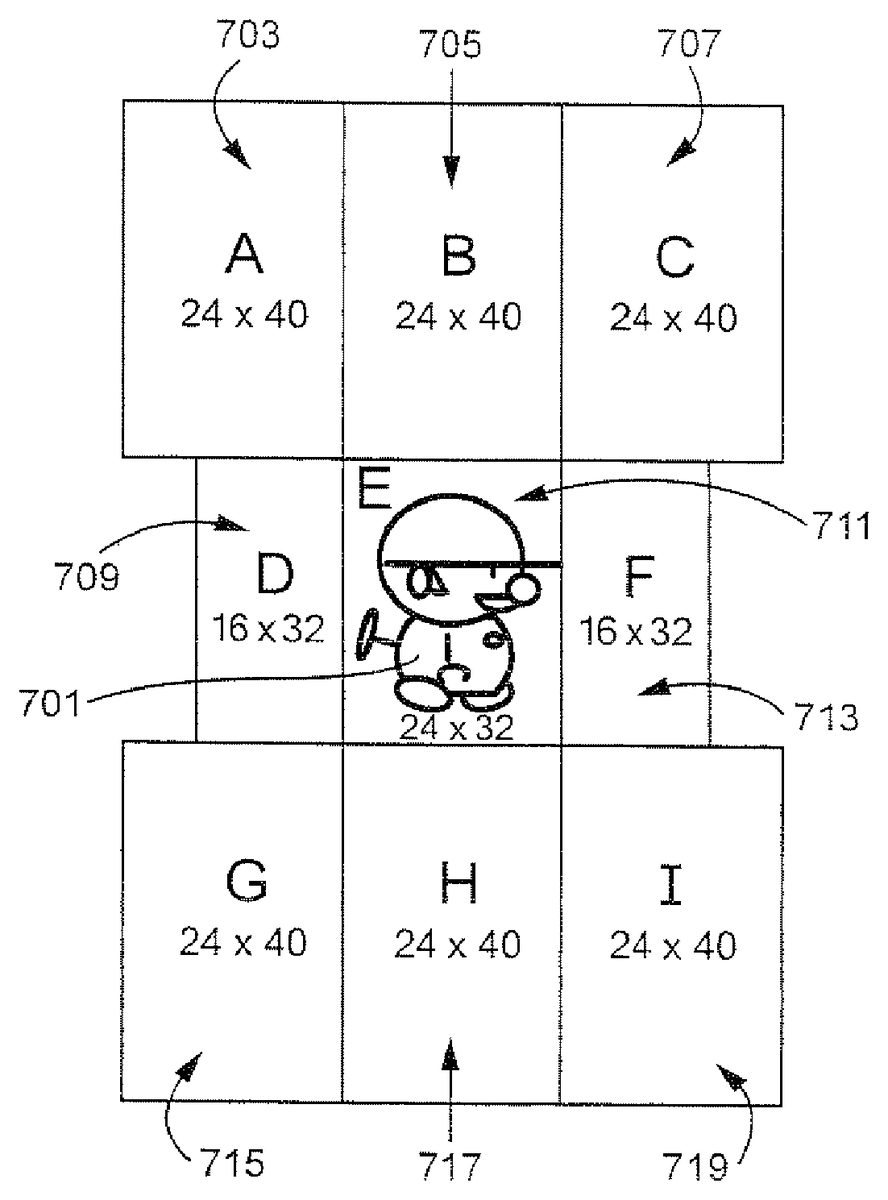
InFIG. 7, an exemplary representation of a game character701is shown, surrounded by a plurality of regions or segments. A centermost region711encompasses the game character in this exemplary non-limiting illustrative implementation. Eight additional regions of various sizes are arranged around the centermost region711in this exemplary illustrative non-limiting implementation. The regions comprise an upper left region703, an upper middle region705, an upper right region707, a center left region709, a center right region713, a lower left region715, a lower middle region717, and a lower right region719. Any number of suitable regions may be used. The regions do not need to be symmetrical or uniform in arrangement or size. It is possible to overlap more than two segments. In that case, it may be desirable to set priority order of detection by assigning priority numbers or values to the segments. Priority can be changed as desired or convenient.
In this exemplary illustrative non-limiting implementation, a user can instruct a character to move or act based on movement from one region to another. No matter where the stylus starts, as long as it passes through one of the rectangles, the system will detect its path and respond accordingly. For example, movement from the centermost region711to the upper left region703might cause the character701to jump. But movement doesn't have to be only between two regions. As another example, if the character is facing right, movement from the centermost region711through the center left region709to the upper middle region705, might cause the character701to flip to face left and then jump. Any number of actions may be linked to different movements and movement patterns between regions.
FIG. 8shows a state diagram of an exemplary illustrative non-limiting implementation of various actions associated with exemplary stylus movement. While the stylus may initially touch the screen at any point, in one exemplary non-limiting illustrative implementation the program controlling movement does not begin tracking stylus stroke path until the stylus passes into one of a plurality of regions. Each state A, B, C, D, F, G, H, I represents motion from an initial stylus position (E) to a newer detectable stylus position the user can distinguish from the other states. In this particular implementation, the exemplary nine regions are represented by states A-I801,803,805,807,817,809,811,813,815. The state diagram represents possible actions that could be taken by the digital object if the stylus passes through a series of exemplary regions. For example, if the stylus stroke begins in A801and moves to E817, the object stops acting, or does nothing if it is already stopped. In another example, if the stylus begins in E817and moves to F807and then to B803, the object faces right and then jumps. While these actions and patterns are described with respect to an exemplary implementation, any number of suitable states and transitions may be added to provide for any suitable actions or a series of actions.
See the following table summarizing such state transitions:
E ----> A = JumpE ----> B = JumpE ----> C = JumpE ----> D = LeftE ----> F = RightE ----> G = Down (Stop in case of no pipe)E ----> H = Down (Stop in case of no pipe)E ----> I = Down (Stop in case of no pipe)E ----> D --->A = Flip left and Jump (If facing to left, jump only)E ----> D ---->B = Flip left and Jump (If facing to left, jump only)E ----> F ---->B = Flip right and Jump (If facing to right, jump only)E ----> F ---->C = Flip right and Jump (If facing to right, jump only)E ----> F ---->H = Flip right and stop or down (If facing to right, stop ordown only)E ----> F --->I = Flip right and stop or down (If facing to right, stop ordown only)E ----> D ---->G = Flip left and stop or down (If facing to left, stop ordown only)E ----> D ---->H = Flip left and stop or down (If facing to left, stop ordown only)A ----> E = StopB ----> E = StopC----> E = StopD ----> E = StopE ----> E = No Action (not move)F ----> E = StopG ----> E = StopH ----> E = StopI ----> E = Stop=A ----> A = No ActionB ----> B = No Action...I----> I = No Action
Exemplary Rotation Directional Control Based on Stylus Touch
While the examples above refer primarily to translational motion of animated game characters, the technology herein can also be used to control different and/or additional types of movement such as for example rotational motion.FIG. 9Ashows an additional exemplary illustrative non-limiting implementation using stylus touch to control the direction of rotational and translational movement of an animated character within a video game. In the example shown inFIG. 9A, the game character has encountered a bar that the game character can swing around.FIG. 9Bshows an example touch control wheel that can be displayed on the same or different display screen as the character and bar. By touching and dragging theFIG. 9Bwheel, the game player can control the motion of the game character as it spins or swings around the bar. For example, by using the stylus to turn theFIG. 9Bwheel, it is possible to control the game character to spin at different rates around the bar. Furthermore, as shown inFIG. 9A, it is possible to draw gestures using the stylus in different areas of the display screen to cause the displayed game character to perform additional actions (e.g., jump off the bar and descend based on a downward stylus stroke; jump off the bar and ascend upwardly based on a downward stylus stroke; or move back and forth horizonally on the bar and/or jump off the bar and move sideways based on a leftward or rightward stroke. In the example shown, the stylus position range can be made larger (e.g., 6 pixels each way in one exemplary illustrative non-limiting implementation), but the specific range and the angles of the vectors used to identify the areas are based on design choice. The stylus sense range can be reduced if desired when the game character is not engaged in spinning round the bar.
While the technology herein has been described in terms of exemplary illustrative non-limiting implementations, it is understood that these implementations are provided by way of example only. For example, while a stylus contacting a touch screen is described above, strokes made using any other means (e.g., a finger on a touch pad, a handheld controller motion or a light pen tracing a path of a cursor on a television screen, etc.) are also possible. The invention is to be defined by the scope of the claims.
Claims
- A computing apparatus comprising: a display device that is coupled to at least one touch-enabled display screen configured to receive touch input;and a processing system that includes at least one processing circuit in communication with a memory device and the display device, the processing system cooperating with the display device to: execute a video game application program that causes an image of a virtual space to be generated and displayed on the touch-enabled display screen, where a virtual object is located within the virtual space, the video game application program dividing the touch-enabled display screen into at least a first detection area and a second detection area for receiving touch input that is used for controlling the virtual object within the virtual space;detect, in the first detection area of the touch-enabled display screen, a first continuous touch input on the touch-enabled display screen that includes at a first detected touch position and a second detected touch position that is different from the first detected touch position;responsive to detection of the first continuous touch input, control, based on a geometric relationship between the first touch position and the second touch position of the first continuous touch input, the virtual object to perform a first type of action within the virtual game space;detect, in the second detection area of the touch-enabled display screen, a second continuous touch input on the touch-enabled display screen that includes at least a third detected touch position and a fourth detected touch position that is different from the third detected touch position;and responsive to detection of the second continuous touch input, control, based on how the second continuous touch input is moved from at least the third touch position to the fourth touch position, the virtual object to perform a second type of action within the virtual game space that is different from the first type of action, wherein the virtual object is moved within the virtual game space based on the performed first type of action and the performed second type of action.
- The computing apparatus of claim 1 , wherein the second type of action is a rotation within the virtual game space and the first type of action is a translation within the virtual game space.
- The computing apparatus of claim 1 , wherein the processing system is further configured to: determine if the first touch position is within an area associated with where the virtual object is displayed on the touch screen;and select the virtual object based on determining the first touch position to be within the area, wherein the virtual object is controlled to perform the first type of action further based on selection thereof.
- The computing apparatus of claim 1 , wherein the processing system is further configured to: cause at least one touch control image to be concurrently displayed, with the display of the virtual object, on the at least one touch-enabled display screen in an area that corresponds to the second detection area, wherein the virtual object is controlled to perform the second type of action further based on how the second continuous touch input corresponds to touch screen positions that are associated with where the touch control image is displayed on the at least one touch-enabled display screen.
- The computing apparatus of claim 1 , wherein the at least one touch-enabled display screen includes a first and second touch-enabled display screens that respectively correspond to the first detection area and the second detection area.
- The computing apparatus of claim 1 , wherein the first detection area and the second detection area are on the same display screen.
- The computing apparatus of claim 1 , wherein the virtual object is controlled to perform the first type of action further based on which one of plural areas of the display screen the first continuous touch input was drawn within.
- The computing apparatus of claim 7 , wherein the plural areas are generated dynamically based on the first touch position.
- The computing apparatus of claim 7 , wherein the plural areas are based on a position that the virtual object is displayed on the display screen.
- The computing apparatus of claim 7 , wherein the first type of action includes plural different movement actions for the virtual object to perform and each of the plural areas is related to a different one of the plural movement actions that cause, upon selection of an area of the plural areas, the virtual object to perform the movement action related to the selected area.
- A computing apparatus comprising: a display device that is coupled to at least one touch-enabled display screen configured to receive touch input;and a processing system that includes at least one hardware processor that is configured to communicate with a memory device and the display device, the processing system cooperating with the display device to: execute a video game application program that causes a virtual object located in a virtual game space to be displayed on the touch-enabled display screen of the display device, the video game application program dividing the touch-enabled display screen into at least a first detection area and a second detection area for receiving touch input that is for use in executing the video game application program;detect, in the first detection area of the touch-enabled display screen, a first continuous touch input on the touch-enabled display screen that includes at least a first detected touch position and a second detected touch position that is different from the first touch position;responsive to detection of the first continuous touch input, control, based on a geometric relationship between the first touch position and the second touch position of the first continuous touch input, the virtual object to perform a first type of action within the virtual game space;cause at least one touch control image to be concurrently displayed, with the display of the virtual object, on the at least one touch-enabled display screen in an area that corresponds to the second detection area, detect, in the second detection area of the touch-enabled display screen and corresponding to where that at least one touch control image is displayed, a third touch input that includes a touch detected at a third touch position;and responsive to detection of the third touch input, control, based on how the third touch position corresponds to a location on the touch-enabled display screen that is associated with where the at least one touch control image is concurrently displayed, the virtual object to perform a second type of action within the virtual game space that is different from the first type of action, wherein the virtual object is moved within the virtual game space based on the performed first type of action and the performed second type of action.
- The computing apparatus of claim 11 , wherein the third touch input is a continuous touch input that includes, along with the third touch position, a fourth touch position that has been detected, wherein control of the virtual object to perform the second type of action is further based on movement of the continuous touch input from the third touch position to the fourth touch position.
- The computing apparatus of claim 11 , wherein the second type of action is rotation within the virtual game space and the first type of action is translation within the virtual game space.
- The computing apparatus of claim 11 , wherein the first detection area and the second detection area are on the same display screen.
- A non-transitory computer readable storage medium storing computer readable instructions for execution by a processing system of a computer, the processing system including at least one hardware processor coupled to electronic memory and a display device that includes a touch-enabled display screen, the stored computer readable instructions comprising instructions that cause the processing system to: execute a video game application program that causes a virtual object located in a virtual game space to be displayed on the touch-enabled display screen of the display device, the video game application program dividing the touch-enabled display screen into at least a first detection area and a second detection area for receiving touch input that is for use in executing the video game application program;detect, in the first detection area of the touch-enable display screen, a first continuous touch input on the touch-enabled display screen that includes at least a first detected touch position and a second detected touch position that is different from the first touch position;responsive to detection of the first continuous touch input, control, based on a geometric relationship between the first touch position and the second touch position of the first continuous touch input, the virtual object to perform a first type of action within the virtual game space;detect, in the second detection area of the touch-enabled display screen, a second continuous touch input on the touch-enabled display screen that includes at least a third detected touch position and a fourth detected touch position that is different from the third touch position;and responsive to detection of the second continuous touch input, control, based on how the second continuous touch input is moved from at least the third touch position to the fourth touch position, the virtual object to perform a second type of action within the virtual game space that is different from the first type of action, wherein the virtual object is moved within the virtual game space based on the performed first type of action and the performed second type of action.
- The non-transitory computer readable storage medium of claim 15 , wherein the stored computer readable instructions comprise further instructions that cause the processing system to cause at least one touch control image to be concurrently displayed, with the display of the virtual object, on the at least one touch-enabled display screen in an area that corresponds to the second detection area, wherein the virtual object is controlled to perform the second type of action further based on how the second continuous touch input corresponds to touch screen positions that are associated with where the touch control image is displayed on the at least one touch-enabled display screen.
- The non-transitory computer readable storage medium of claim 15 , wherein the second type of action is rotation within the virtual game space and the first type of action is translation within the virtual game space.
- The non-transitory computer readable storage medium of claim 15 , wherein the virtual object is controlled to perform the first type of action further based on which one of plural areas of the display screen the first continuous touch input was detected within.
- The non-transitory computer readable storage medium of claim 18 , wherein the plural areas are generated dynamically based on the first touch position.
- The non-transitory computer readable storage medium of claim 18 , wherein the plural areas are based on a position that the virtual object is displayed on the display screen.
Disclaimer: Data collected from the USPTO and may be malformed, incomplete, and/or otherwise inaccurate.