U.S. Pat. No. 9,417,761
STORAGE MEDIUM STORING IMAGE PROCESSING PROGRAM, IMAGE PROCESSING APPARATUS, IMAGE PROCESSING METHOD AND IMAGE PROCESSING SYSTEM FOR DISPLAYING A VIRTUAL SPACE IN WHICH OBJECTS ARE ARRANGED WITH A VIRTUAL CAMERA
AssigneeNINTENDO CO., LTD.
Issue DateAugust 15, 2011
Illustrative Figure
Abstract
An image processing apparatus writes a virtual space image obtained by imaging a virtual space in which objects are arranged from a virtual camera to an output area. When a pointer image representing a positional relationship between a referential position and an arrangement position of the object is depicted on the virtual space image stored in the output area, the pointer image to be depicted is changed in correspondence with conditions, such as the height of the virtual camera and the attribute of the object.
Description
DETAILED DESCRIPTION OF THE PREFERRED EMBODIMENTS Referring toFIG. 1, a game system10of one embodiment of the present invention includes a game apparatus12and a controller14. Although illustration is omitted, the game apparatus12of this embodiment is designed such that it can be connected to four controllers14at the maximum. Furthermore, the game apparatus12and each of the controllers14are wirelessly connected. For example, the wireless communication is executed according to an MP (Multilink Protocol) or Bluetooth (registered trademark) standard, but may be executed by other standards such as infrared rays, a wireless LAN, etc. Alternatively, they may be connected by wire. The game apparatus12includes a roughly rectangular parallelepiped housing16, and the housing16is furnished with a disk slot18on a front surface. From the disk slot18, an optical disk24as one example of an information storage medium storing a game program, etc. is inserted to be loaded into a disk drive54(seeFIG. 2) within the housing16. Although the illustration is omitted, around the disk slot18, an LED and a light guide plate are arranged so as to make the disk slot18light up and off or flash in response to various processing. Furthermore, on a front surface of the housing16of the game apparatus12, a power button20aand a reset button20bare provided at the upper part thereof, and an eject button20cis provided below them. In addition, a connector cover for external memory card22is provided between the reset button20band the eject button20c, and in the vicinity of the disk slot18. Inside the connector cover for external memory card22, a connector for external memory card62(seeFIG. 2) is provided, through which an external memory card38(hereinafter simply referred to as a “memory card38”) not shown is inserted. The memory card is employed for loading the game program, etc. read from the optical disk24to temporarily store it, storing (saving) game data (result data, proceeding data of the ...
DETAILED DESCRIPTION OF THE PREFERRED EMBODIMENTS
Referring toFIG. 1, a game system10of one embodiment of the present invention includes a game apparatus12and a controller14. Although illustration is omitted, the game apparatus12of this embodiment is designed such that it can be connected to four controllers14at the maximum. Furthermore, the game apparatus12and each of the controllers14are wirelessly connected. For example, the wireless communication is executed according to an MP (Multilink Protocol) or Bluetooth (registered trademark) standard, but may be executed by other standards such as infrared rays, a wireless LAN, etc. Alternatively, they may be connected by wire.
The game apparatus12includes a roughly rectangular parallelepiped housing16, and the housing16is furnished with a disk slot18on a front surface. From the disk slot18, an optical disk24as one example of an information storage medium storing a game program, etc. is inserted to be loaded into a disk drive54(seeFIG. 2) within the housing16. Although the illustration is omitted, around the disk slot18, an LED and a light guide plate are arranged so as to make the disk slot18light up and off or flash in response to various processing.
Furthermore, on a front surface of the housing16of the game apparatus12, a power button20aand a reset button20bare provided at the upper part thereof, and an eject button20cis provided below them. In addition, a connector cover for external memory card22is provided between the reset button20band the eject button20c, and in the vicinity of the disk slot18. Inside the connector cover for external memory card22, a connector for external memory card62(seeFIG. 2) is provided, through which an external memory card38(hereinafter simply referred to as a “memory card38”) not shown is inserted. The memory card is employed for loading the game program, etc. read from the optical disk24to temporarily store it, storing (saving) game data (result data, proceeding data of the game, or replay data described later) of the game played by means of the game system10, and so forth. Here, storing the game data described above may be performed on an internal memory, such as a flash memory44(seeFIG. 2) provided inside the game apparatus12in place of the memory card38. Also, the memory card38may be utilized as a backup memory of the internal memory. In addition, in the game apparatus12, an application other than the game can be executed, and in such a case, data of the other application can be saved in the memory card38.
It should be noted that a general-purpose SD card can be employed as a memory card38, but other general-purpose memory cards, such as memory sticks, multimedia cards (registered trademark) can be employed. The memory card38can be utilized in another game apparatuses12A having a construction similar to the game apparatus12, and thus, it is possible to offer the game data to other players via the memory card38.
Although omitted inFIG. 1, the game apparatus12has an AV cable connector58(seeFIG. 2) on the rear surface of the housing16, and by utilizing the AV cable connector58, a monitor28and a speaker30are connected to the game apparatus12through an AV cable26. The monitor28and the speaker30are typically a color television receiver, and through the AV cable26, a video signal from the game apparatus12is input to a video input terminal of the color television, and a sound signal from the game apparatus12is input to a sound input terminal thereof. Accordingly, a virtual three-dimensional game image of a three-dimensional (3D) video game, for example, is displayed on the screen of the color television (monitor)28, and stereo game sound, such as a game music, a sound effect, etc. is output from right and left speakers30. Around the monitor28(on the top side of the monitor28, in this embodiment), a marker unit32including two infrared ray LEDs (markers)32A and32B is provided. The marker unit32is connected to the game apparatus12through a power source cable32c. Accordingly, the marker unit32is supplied with power from the game apparatus12. Thus, the markers32A and32B emit light beams so as to output infrared rays ahead of the monitor28.
Furthermore, the power of the game apparatus12is applied by means of a general AC adapter (not illustrated). The AC adapter is inserted into a standard wall socket for home use, and the game apparatus12transforms the house current (commercial power supply) to a low DC voltage signal suitable for driving. In another embodiment, a battery may be utilized as a power supply.
The controller14, which is described in detail later, includes a first controller34and a second controller36each capable of being held with one hand as a first operation unit and a second operation unit, respectively. A cable36ahas one end extending from the rear end of the second controller36and the other end provided with a connector36b. The connector36bis connected to a connector34a(FIG. 3,FIG. 5) provided on a rear end surface of the first controller34. Input data obtained by the second controller36is applied to the first controller34through the cable36a. The first controller34transmits controller data including the input data of the first controller34itself and the input data of the second controller36to the game apparatus.
In the game system10, a user or a player turns the power of the game apparatus12on for playing the game (or applications other than the game) by a power switch20a. Then, the user selects an appropriate optical disk24recording a program of a video game (or other applications the player wants to play), and loads the optical disk24into the disk drive54of the game apparatus12. In response thereto, the game apparatus12starts to execute the video game or the other applications on the basis of the program recorded in the optical disk24. The user operates the controller14in order to apply an input to the game apparatus12. For example, by operating any one of the operating buttons of the operating portion82, a game or other application is started. Besides the operation performed on operating portion82, by moving the controller14itself, it is possible to move a moving image object (player object) in different directions or change the perspective of the user (camera position of the virtual game) in a three-dimensional game world.
It should be noted that the video game and other application programs are stored (installed) in an internal memory (flash memory44(seeFIG. 2)) of the game apparatus12, and may be executed in the internal memory. In such a case, a program stored in a storage medium like an optical disk24may be installed in the internal memory, and the downloaded program may be installed in the internal memory.
FIG. 2is a block diagram showing an electric configuration of the game system10shown inFIG. 1embodiment. Although illustration is omitted, respective components within the housing16are mounted on a printed board. As shown inFIG. 2, the game apparatus12has a CPU40functioning as a game processor. The CPU40is connected with a system LSI42. The system LSI42is connected with an external main memory46, a ROM/RTC48, the disk drive54, and an AV IC56.
The external main memory46is utilized as a work area and a buffer area of the CPU40by storing programs like a game program, etc. and various data. The ROM/RTC48, which is a so-called boot ROM, is incorporated with a program for activating the game apparatus12, and is provided with a time circuit for counting a time. The disk drive54reads program, texture data etc. from the optical disk24, and writes them in an internal main memory42edescribed later or the external main memory46under the control of the CPU40.
The system LSI42is provided with an input-output processor42a, a GPU (Graphics Processor Unit)42b, a DSP (Digital Signal Processor)42c, a VRAM42dand an internal main memory42e, and these are connected with one another by internal buses although illustration is omitted. The input-output processor (I/O processor)42aexecutes transmission and reception of data and executes download of the data. The GPU42bis made up of a part of a depicting means, and receives a graphics command (construction command) from the CPU40to generate game image data according to the command. Additionally, the CPU40applies an image generating program required for generating game image data to the CPU42bin addition to the graphics command.
Although illustration is omitted, the GPU42bis connected with the VRAM42das described above. The GPU42baccesses the VRAM42dto acquire data (image data: data such as polygon data, texture data, etc.) required to execute the construction command. Here, the CPU40writes image data required for depicting to the VRAM42dvia the GPU42b. The GPU42baccesses the VRAM42dto create game image data for depicting.
In this embodiment, a case that the GPU42bgenerates game image data is explained, but in a case that an arbitrary application except for the game application is executed, the GPU42bgenerates image data as to the arbitrary application.
Furthermore, the DSP42cfunctions as an audio processor, and generates audio data corresponding to a sound, a voice, music, or the like to be output from the speaker30by means of the sound data and the sound wave (tone) data stored in the internal main memory42eand the external main memory46.
The game image data and audio data generated as described above are read by the AV IC56, and output to the monitor28and the speaker30via the AV connector58. Accordingly, a game screen is displayed on the monitor28, and a sound (music) necessary for the game is output from the speaker30.
Furthermore, the input-output processor42ais connected with a flash memory44, a wireless communication module50and a wireless controller module52, and is also connected with an expansion connector60and a connector for external memory card62. The wireless communication module50is connected with an antenna50a, and the wireless controller module52is connected with an antenna52a.
The input-output processor42acan communicate with other game apparatuses and servers (both of them are not shown) to be connected to a network via the wireless communication module50. The input-output processor42aperiodically accesses the flash memory44to detect the presence or absence of data (referred to as data to be transmitted) being required to be transmitted to a network, and transmits it to the network via the wireless communication module50and the antenna50ain a case that data to be transmitted is present. Furthermore, the input-output processor42areceives data (referred to as received data) transmitted from another game apparatuses via the network, the antenna50aand the wireless communication module50, and stores the received data in the flash memory44. In a ease that the received data does not satisfy a predetermined condition, the reception data is abandoned as it is. In addition, the input-output processor42acan receive data (download data) downloaded from the server connected to the network via the network the antenna50aand the wireless communication module50, and store the download data in the flash memory44.
Furthermore, the input-output processor42areceives input data transmitted from the controller14via the antenna52aand the wireless controller module52, and (temporarily) stores it in the buffer area of the internal main memory42eor the external main memory46. The input data is erased from the buffer area after being utilized in processing (game processing, for example) by the CPU40.
Here, the input-output processor42acan communicate with another game apparatus directly without passing through the network via the wireless communication module50.
In addition, the input-output processor42ais connected with the expansion connector60and the connector for external memory card62. The expansion connector60is a connector for interfaces, such as USB, SCSI, etc., and can be connected with medium such as an external storage and peripheral devices such as another controller different from the controller14. Furthermore, the expansion connector60is connected with a cable LAN adaptor, and can utilize the cable LAN in place of the wireless communication module50. The connector for external memory card62can be connected with an external storage like a memory card38. Thus, the input-output processor42a, for example, accesses the external storage via the expansion connector60and the connector for external memory card62to store and read the data.
Although a detailed description is omitted, as shown inFIG. 1as well, the game apparatus12(housing16) is furnished with the power button20a, the reset button20b, and the eject button20c. The power button20ais connected to the system LSI42. When the power button20ais turned on, the system LSI42is set to a mode of a normal energized state (referred to as “normal mode”) in which the respective components of the game apparatus12are supplied with power through an AC adapter not shown. On the other hand, when the power button20ais turned off, the system LSI42is set to a mode (hereinafter referred to as “standby mode”) in which a part of the components of the game apparatus12is supplied with power, and the power consumption is reduced to minimum.
In this embodiment, in a case that the standby mode is set, the system LSI42issues an instruction to stop supplying the power to the components except for the input-output processor42a, the flash memory44, the external main memory46, the ROM/RTC48and the wireless communication module50, and the wireless controller module52. Accordingly, in this embodiment, in the standby mode, the CPU40never executes an application.
The reset button20bis also connected to the system LSI42. When the reset button20bis pushed, the system LSI42restarts a start-up program of the game apparatus12. The eject button20cis connected to the disk drive54. When the eject button20cis pushed, the optical disk24is ejected from the disk drive54.
FIG. 3shows one example of an external appearance of the first controller34.FIG. 3(A) is a perspective view of the first controller34as seeing it from above rear, andFIG. 3(B) is a perspective view of the first controller34as seeing it from below front. The first controller34has a housing80formed by plastic molding, for example. The housing80is formed into an approximately rectangular parallelepiped shape regarding a back and forth direction (Z-axis direction shown inFIG. 3) as a longitudinal direction, and has a size small enough to be held by one hand of a child and an adult. As one example, the housing80has a length or a width approximately the same as that of the palm of the person. A player can perform a game operation by means of the first controller34, that is, by pushing buttons provided on it and by changing a position and a direction of the first controller34by moving the first controller34itself.
The housing80is provided with a plurality of operation buttons (operation key). That is, on the top surface of the housing80, a cross key82a, a 1 button82b, a 2 button82c, an A button82d, a −button82e, a menu button82f, and a +button82gare provided. Meanwhile, on the bottom surface of the housing80, a concave portion is formed, and on the reward inclined surface of the concave portion, a B button82his provided. Each of the buttons (switches)82a-82his assigned an appropriate function according to a game program to be executed by the game apparatus12. Furthermore, on the top surface of the housing80, a power switch82ifor turning on/off the power of the main body of the game apparatus12from a remote place is provided. The respective buttons (switches) provided on the first controller34may inclusively be indicated with the use of the reference numeral82.
At the back surface of the housing80, the above-described connector34ais provided. The connector34ais a 32 pin edge connector, for example, and utilized for connecting other devices to the first controller34. In this embodiment, the connector34ais connected with the connector36bof the second controller36. At the back end of the top surface of the housing80, a plurality of LEDs84are provided, and the plurality of LEDs84show a controller number (identification number of the controller) of the controller14. The game apparatus12can be connected with a maximum four controllers14, for example. If a plurality of controllers14are connected to the game apparatus12, a controller number is applied to the respective controllers14in the connecting order, for example. Each LED84corresponds to the controller number, and the LED84corresponding to the controller number lights up.
Furthermore, inside the housing80of the first controller34, an acceleration sensor86(FIG. 5) is provided. As an acceleration sensor86, acceleration sensors of an electrostatic capacity type can typically be utilized. The acceleration sensor86detects accelerations of a linear component for each sensing axis and gravitational acceleration out of the accelerations applied to a detection portion of the acceleration sensor. More specifically, in this embodiment, a three-axis acceleration sensor is applied to detect the respective accelerations in directions of three axes of a up and down direction (Y-axial direction shown inFIG. 3), a right and left direction (X-axial direction shown inFIG. 3), and a forward and rearward direction (Z-axial direction shown inFIG. 3) of the first controller34.
It should be noted that as an acceleration sensor86, two-axis acceleration sensors may be utilized for detecting any two of the directions of the accelerations out of the up and down direction, the right and left direction and the back and forth direction according to the shape of the housing80, the limitation on how to hold the first controller34, or the like. Under certain circumstances, a one-axis acceleration sensor may be used.
In addition, the first controller34has an imaged information arithmetic section88(seeFIG. 5). As shown inFIG. 3(B), on the front end surface of the housing80, a light incident opening90of the imaged information arithmetic section88is provided, and from the light incident opening90, infrared rays emitted by the markers44mand44nof the sensor bar44are captured.
FIG. 4shows one example of an appearance of the second controller36.FIG. 4(A) is a perspective view of the second controller36as seeing it from above rear, andFIG. 4(B) is a perspective view of the second controller36as seeing it from below front. Additionally, inFIG. 4, the cable36aof the second controller36is omitted.
The second controller36has a housing92formed by plastic molding, for example. The housing92is formed into an approximately thin long elliptical shape in the forward and backward directions (Z-axis direction inFIG. 4) when viewed from plan, and the width of the right and left direction (X-axis direction inFIG. 4) at the back end is narrower than that of the front end. Furthermore, the housing92has a curved shape as a whole when viewed from a side, and downwardly curved from a horizontal portion at the front end to the back end. The housing92has a size small enough to be held by one hand of a child and an adult similar to the first controller34as a whole, and has a longitudinal length (in the Z-axis direction) slightly shorter than that of the housing80of the first controller34. Even with the second controller36, the player can perform a game operation by operating buttons and a stick, and by changing a position and a direction of the controller by moving itself.
At the end of the top surface of the housing92, an analog joystick94ais provided. At the end of the housing92, a front edge slightly inclined backward is provided, and on the front edge are provided a C button94band a Z button94cvertically arranged (Y-axis direction inFIG. 4). The analog joystick94aand the respective buttons94band94care assigned appropriate functions according to a game program to be executed by the game apparatus12. The analog joystick94aand the respective buttons94hand94cprovided to the second controller36may be inclusively denoted by means of the reference numeral94.
Inside the housing92of the second controller36, an acceleration sensor96(FIG. 5) is provided. As the acceleration sensor96, an acceleration sensor similar to the acceleration sensor86in the first controller34is applied. More specifically, the three-axis acceleration sensor is applied in this embodiment, and detects accelerations in the respective three axis directions like an up and down direction (Y-axial direction shown inFIG. 4), a right and left direction (X-axial direction shown inFIG. 4), and a forward and backward direction (Z-axial direction shown inFIG. 4) of the second controller36.
Additionally, the shapes of the first controller34shown inFIG. 3and the second controller36shown inFIG. 4and the shape, the number and the setting position of the buttons (switches, stick, or the like), etc. are merely one example, and can be changed to other shapes, numbers and setting positions, etc. as needed.
Furthermore, the controller34is powered by a battery (not illustrated) detachably housed in the first controller34. The second controller36is supplied with the power through the connector34a, the connector40, and the cable36a.
FIG. 5shows one example of an electric configuration of the controller14when the first controller34and the second controller36are connected with each other. The first controller34contains a communication unit98, and the communication unit98is connected with the operating portion82, the acceleration sensor86, the imaged information arithmetic section88and the connector34a. The operating portion82indicates the above-described operation buttons or operating switches82a-82i. When the operating portion82is operated, an operation signal (key information) is applied to the communication unit98. The data indicative of acceleration detected by the acceleration sensor86is output to the communication unit98. The acceleration sensor86has in the order of a maximum sampling period of 200 frames per second.
The data taken in by the imaged information arithmetic section88is also output to the communication unit98. The imaged information arithmetic section88is constituted by an infrared filter100, a lens102, an imager104and an image processing circuit106. The infrared filter100passes only infrared rays from the light incident from the light incident opening90at the front of the first controller34. As described above, the markers44mand44nof the sensor bar44placed near (around) the display screen of the monitor30are infrared LEDs for outputting infrared lights forward the monitor30. Accordingly, by providing the infrared filter100, it is possible to image the image of the markers44mand44nmore accurately. The lens102condenses the infrared rays passing thorough the infrared filter100to emit them to the imager104. The imager104is a solid imager, such as a CMOS sensor and a CCD, for example, and images the infrared rays condensed by the lens102. Accordingly, the imager104images only the infrared rays passing through the infrared filter100to generate image data. Hereafter, the image imaged by the imager104is called an “imaged image”. The image data generated by the imager104is processed by the image processing circuit106. The image processing circuit106calculates positions of objects to be imaged (markers44mand44n) within the imaged image, and outputs marker coordinates data including each coordinate value indicative of the position to the communication unit98for each predetermined time (one frame, for example). It should be noted that a description of the image processing circuit106is made later.
The connector34ais connected with the connector36bof the cable36aextending from the second controller36. The connector36bis connected with the operating portion94and the acceleration sensor96of the second controller36. The operating portion94denotes the above-described analog joystick94aand operation buttons94band94c. When the operating portion94is operated, an operation signal is applied to the communication unit98via the cable36a, the connector36b, the connector34a, etc. The acceleration sensor96also has a sampling period similar to that of the acceleration sensor86, and applies the data indicative of the detected acceleration to the communication unit98.
The communication unit98includes a microcomputer (micon)108, a memory110, a wireless module78and an antenna112. The micon108transmits the obtained data to the game apparatus12and receives data from the game apparatus12by controlling the wireless module78while using the memory110as a memory area (working area and buffer area) in processing.
The data output from the operating portion82, the acceleration sensor86and the imaged information arithmetic section88of the first controller34, and the operating portion94and acceleration sensor96of the second controller36to the micon108is temporarily stored in the memory110. The wireless transmission from the communication unit98to the Bluetooth communication unit76of the game apparatus12is performed every predetermined cycle. The game processing is generally performed by regarding 1/60 seconds as a unit, and therefore, it is necessary to perform the transmission from the first controller34at a cycle equal to or shorter than it. The micon108outputs data including the operation data of the operating portions82and94and the acceleration data of the acceleration sensors86and96, and marker coordinates data from the imaged information arithmetic section88stored in the memory110to the wireless module78as controller data when transmission timing to the game apparatus12has come. The wireless module78modulates a carrier of a predetermined frequency by the controller data, and emits its weak radio wave signal from the antenna112by using a short-range wireless communication technique, such as Bluetooth. Namely, the controller data is modulated to the weak radio wave signal by the wireless module78and transmitted from the first controller34. The weak radio wave signal is received by the Bluetooth communication unit76of the game apparatus12. The weak radio wave thus received is subjected to demodulating and decoding processing, thus making it possible for the game apparatus12to obtain the controller data. The CPU46of the game apparatus12performs the game processing on the basis of the controller data obtained from the controller14.
It will be appreciated by those skilled in the art from the description of this specification that a computer, such as a processor (CPU46, for example) of the game apparatus12or the processor (micon108, for example) of the controller14executes processing on the basis of an acceleration signal output from the acceleration sensors86and96, and whereby, more information relating to the controller14can be estimated or calculated (determined). In a case that processing is executed on the side of the computer assuming that the first controller34and second controller36respectively incorporated with the acceleration sensors86and96are in a static state (that is, processing is executed considering that accelerations detected by the acceleration sensors86and96are only gravitational accelerations), if the first controller34and the second controller36are actually in a static state, it is possible to know whether or not the orientations of the first controller34and the second controller36are inclined with respect to the direction of gravity or to what extent they are inclined on the basis of the detected acceleration. More specifically, when a state in which the detection axes of the acceleration sensors86and96are directed to a vertically downward direction is taken as a reference, merely whether or not 1G (gravitational acceleration) is imposed on can show whether or not each of the first controller34and the second controller36is inclined, and the size can show to what extent each of them is inclined. Furthermore, if a multi-axes acceleration sensor is applied, by further performing processing on an acceleration signal of each axis, it is possible to more precisely know to what extent the first controller34and the second controller36are inclined with respect to the direction of gravity. In this case, on the basis of outputs from the acceleration sensors86and96, the computer may perform processing of calculating data of inclined angles of the first controller34and second controller36, but perform processing of estimating an approximate inclination on the basis of the outputs from the acceleration sensors86and96without performing the processing of calculating the data of the inclined angle. Thus, by using the acceleration sensors86and96in conjunction with the computer, it is possible to determine an inclination, an orientation or a position of each of the first controller34and second controller36.
On the other hand, assuming that the acceleration sensors86and96are in a dynamic state, accelerations according to the movement of the acceleration sensors86and96are detected in addition to the gravitational acceleration component, and therefore, if the gravitational acceleration component is removed by predetermined processing, it is possible to know a moving direction, etc. More specifically, in a case that the first controller34and the second controller36respectively being furnished with the acceleration sensors86and96are accelerated and moved by the hands of the user, acceleration signals generated by the acceleration sensors86and96are processed by the above-described computer, and whereby, it is possible to calculate various movements and/or positions of the first controller34and the second controller36. Additionally, even when assuming that the acceleration sensors86and96are in a dynamic state, if an acceleration in correspondence with the movement of each of the acceleration sensors86and96is removed by the predetermined processing, it is possible to know the inclination with respect to the direction of gravity. In another embodiment, each of the acceleration sensors86and96may contain a built-in signal processing apparatus or other kinds of dedicated processing apparatuses for performing desired processing on the acceleration signal output from the incorporated acceleration detecting means before outputting the signal to the micon108. For example, in a ease that the acceleration sensors86and96are ones for detecting a static acceleration (gravitational acceleration, for example), the built-in or dedicated processing apparatuses may be ones for transforming the detected acceleration signal into the inclined angle (or other preferable parameters) corresponding thereto.
In this game system10, a user can make an operation or input to the game by moving the controller14. In playing the game, the user holds the first controller34with the right hand and the second controller36with the left hand as shown inFIG. 6. As described above, in this embodiment, the first controller34contains the acceleration sensor86for detecting accelerations in the three-axis directions, and the second controller36also contains the same acceleration sensor96. When the first controller34and the second controller36are moved by the user, acceleration values respectively indicating the movements of the controllers are detected by the acceleration sensor86and the acceleration sensor96. In the game apparatus12, game processing can be executed according to the detected acceleration values.
Furthermore, the first controller34is provided with the imaged information arithmetic section88, and this makes it possible for the user to utilize the first controller34as a pointing device. In this case, the user holds the first controller34with the edge surface (light incident opening90) of the first controller34directed to the markers44mand44n. It should be noted that as understood fromFIG. 1, the markers44mand44nare placed around a predetermined side (top or bottom) of the monitor30in parallel with the predetermined side. In this state, the user can perform a game operation by changing a position on the screen designated by the first controller34by moving the first controller34itself, and by changing distances between the first controller34and each of the markers44mand44n.
FIG. 7is a view explaining viewing angles between the respective markers44mand44n, and the first controller34. As shown inFIG. 7, each of the markers44mand44nemits infrared ray within a range of a viewing angle α. Also, the imager104of the imaged information arithmetic section88can receive incident light within the range of the viewing angle β taking the line of sight of the first controller34(Z axis direction inFIG. 3) as a center. For example, the viewing angle α of each of the markers44mand44nis 34° (half-value angle) while the viewing angle β of the imager104is 42°. The user holds the first controller34such that the imager104is directed and positioned so as to receive the infrared rays from the markers44mand44n. More specifically, the user holds the first controller34such that at least one of the markers44mand44nexists in the viewing angle β of the imager104, and the first controller34exists in at least one of the viewing angles α of the marker44mor44n. In this state, the first controller34can detect at least one of the markers44mand44n. The user can perform a game operation by changing the position and the orientation of the first controller34in the range satisfying the state. Also, in a case that any one of the makers44mand44nis only detected, by setting temporary marker coordinates in place of the other marker which is not detected by means of data detecting the previous two makers44mand44n, a designated position by the first controller34can be calculated.
If the position and the orientation of the first controller34are out of the range, the game operation based on the position and the orientation of the first controller34cannot be performed. Hereafter, the above-described range is called an “operable range.”
If the first controller34is held within the operable range, an image of each of the markers44mand44nis imaged by the imaged information arithmetic section88. That is, the imaged image obtained by the imager104includes an image (object image) of each of the markers44mand44nas an object to be imaged.FIG. 8is an illustrative view showing one example of the imaged image including object images. The image processing circuit106calculates coordinates (marker coordinates) indicative of the position of each of the markers44mand44nin the imaged image by utilizing the image data of the imaged image including the object images44m′ and44n′.
Because the object images44m′ and44n′ appear as high-intensity parts in the image data of the imaged image, the image processing circuit106first detects the high-intensity parts as a candidate of the object images. Next, the image processing circuit106determines whether or not each of the high-intensity parts is an object image on the basis of the size of the detected high-intensity part. The imaged image may include images other than the object image due to sunlight through a window and light of a fluorescent lamp in the room as well as the two object images44m′ and44n′ (marker images). The determination processing whether or not the high-intensity part is an object image is executed for discriminating the images44m′ and44n′ of the two markers44mand44nas object images from the images other than them, and accurately detecting the object images. In order to discriminate the object images44m′ and44n′ in the imaged image from other images, the imaging objects44mand44nare necessary to be known, and in this embodiment, the size is decided in advance, and therefore, it is possible to estimate the size of the marker images44m′ and44n′. Thus, on the basis of the size of the high-intensity part, it is possible to make a determination of the marker images44m′ and44n′. More specifically, in the determination processing, it is determined whether or not each of the detected high-intensity part is within the size of the preset predetermined range. Then, if the high-intensity part is within the size of the predetermined range, it is determined that the high-intensity part represents the object image. On the contrary, if the high-intensity part is not within the size of the predetermined range, it is determined that the high-intensity part represents the images other than the object image.
In addition, as to the high-intensity part which is determined to represent the object image as a result of the above-described determination processing, the image processing circuit106calculates the position of the high-intensity part. More specifically, the barycenter position of the high-intensity part is calculated. Here, the coordinates of the barycenter position is called “marker coordinates”. Also, the barycenter position can be calculated with more detailed scale than the resolution of the imager104. Now, the resolution of the imaged image imaged by the imager104shall be 126×96, and the barycenter position shall be calculated with the scale of 1024×768. That is, the marker coordinates is represented by the integer from (0, 0) to (1024, 768).
Additionally, as shown inFIG. 8, the position in the imaged image is represented in a coordinate system (X-Y coordinate system of the imaged image) by taking the upper left of the imaged image as an original point O, the downward direction as the Y-axis positive direction, and the right direction as the X-axis positive direction.
Furthermore, in a case that the object images44m′ and44n′ are accurately detected, two high-intensity parts are determined as object images by the determination processing, and therefore, it is possible to calculate two marker coordinates. The image processing circuit106outputs data indicative of the calculated two marker coordinates, that is, imaging object data indicative of positions of the imaging objects to the communication unit98. The output imaging object data (marker coordinate data) is included in the controller data by the micon108as described above, and transmitted to the game apparatus12.
When taking in the marker coordinate data from the received controller data, the game apparatus12(CPU46) can calculate a designated position (designated coordinates) of the first controller34on the screen of the monitor30and the distance from the first controller34to each of the markers44mand44non the basis of the marker coordinate data. For example, when the first controller34designates the left end of the monitor30, the object images44m′ and44n′ are detected at the right of the imaged image, and when the first controller34designates the lower end of the screen, the object images44m′ and44n′ are detected at the upper portion of the imaged image. In other words, the marker coordinates on the imaged image are detected at positions reverse to the designated position of the first controller34on the screen. Accordingly, when the coordinates of the designated position of the first controller34are calculated from the marker coordinates, the coordinate system is appropriately transformed from the coordinate system of the imaged image inFIG. 8to a coordinate system for representing positions on the screen.
Additionally, in this embodiment, the first controller34performs predetermined arithmetic processing on the imaged data to detect the marker coordinates, and transmit the marker coordinate data to the game apparatus12. However, in another embodiment, imaged data is transmitted as controller data from the first controller34to the game apparatus12, and the CPU46of the game apparatus12may perform predetermined arithmetic processing on the imaged data to detect the marker coordinates and the coordinates of the designated position.
Furthermore, the distance between the object images in the imaged image is changed depending on the distance between the first controller34and each of the markers44mand44n. Because the distance between the markers44mand44n, the width of the imaged image, and the viewing angle β of the imager104are decided in advance, by calculating the distance between the two marker coordinates, the game apparatus12can calculate the current distance between the first controller34, and each of the markers44mand44n.
Here, how to operate the controllers in the game may be another manner, and the game may be played only by using the first controller34. For example, the game may be played with the first controller34held with both hands.
When a “dowsing game” of this embodiment is played in the game system10configured as described above, the game screens as shown in.FIG. 9toFIG. 12are displayed on the monitor28, for example. The game screen inFIG. 9is a screen for selecting an object being a target to be dowsed (hereinafter, referred to as “target object” or “target”) Obi out of the objects (Ob1, Ob2, . . . : this may simply be described by “Ob” when distinction from one another is not needed) arranged in the virtual space IS, and the game screens inFIG. 10toFIG. 12are screens in which the target object Obi is being searched by dowsing.
The outline is first described. In each of allFIG. 9toFIG. 12, a virtual space image obtained by imaging a virtual space IS where the objects Ob1, Ob2, . . . are arranged with a virtual camera (IC: seeFIG. 14(A), and etc.) is depicted on the game screen. The virtual camera IC corresponds to a viewpoint (first-person perspective) of the player character which makes the search by dowsing. Thus, the image of the player character itself is not displayed on the game screen.
Generally, dowsing is a method of finding underground artifacts, such as underground water and minerals by a movement of a simple tool, for example, rod and pendulum.
In the dowsing game, the player character performs dowsing by using a sword Sw to search for an object Obi. On the game screen, the sword Sw and a pointer Pnt indicating the result (strength and direction) of the dowsing by the sword Sw are displayed. The strength and direction of the dowsing change in correspondence with a positional relationship between the player character having the sword Sw, that is, the virtual camera IC and the object Obi. The pointer Pnt visually represents the positional relationship between the virtual camera IC and the object Obi by a change of the color and the size of the prickle as shown inFIG. 17, for example.
That is, one main feature of this embodiment is in dowsing image processing (seeFIG. 21) of generating an image of the pointer Pnt which changes the manner, such as the color and size of its prickle here in correspondence with the positional relationship between the virtual camera IC and the object Obi, and depicting the pointer image on the game image.
Here, as to the object (Ob1, Ob2, . . . ), the target object Obi is shown by the dotted lines inFIG. 11andFIG. 12for the sake of convenience of description, but the purpose of the dowsing is searching for something underground and thus, it is not displayed on the actual game screen.
The pointer Pnt changes as shown inFIG. 10toFIG. 12in correspondence with the positional relationship between the player character having the sword Sw, that is, the virtual camera IC and the target object Obi.FIG. 10shows a case that the virtual camera IC is far from the object Obi in terms of the distance and the angle, and the pointer Pnt in this state is a simple white circle.
Here, the object of “far in terms of the distance” is an object for which the distance (d4) from the virtual camera IC (viewpoint) is larger than a threshold value (dmax) like an object Ob4shown inFIG. 16(A), for example, and the object of “far in terms of the angle” is an object for which an angle (θ5) formed with respect to an optical axis (glance) of the virtual camera IC is larger than a threshold value (θ max) like an object Ob5.
Thereafter, as shown inFIG. 11andFIG. 12, when the positional relationship between the virtual camera IC and the target object Obi enters a predetermined range (di≦dmax and θ i≦θ max), the pointer Pnt is colored pale blue and has a small prickle. As they approach to each other, the pointer Pnt is colored dark blue and has the prickle increased in size.
That is, in the dowsing game, the sword Sw has a dowsing ability to detect the target object Obi and change the manner of the pointer Pnt from a simple white circle to a blue circle with prickle, and further change the depth of blue and the size of the prickle in correspondence with the positional relationship within the predetermined range.
Accordingly, the player can estimate an approximate position of the object Obi by moving the position of the player character, that is, the virtual camera IC and changing the direction of the glance, that is, the optical axis direction while seeing the changes of the pointer Pnt.
Hereafter, such a predetermined range, that is, a range in which the target object Obi is detected by the dowsing with the sword Sw (di≦dmax, θ i≦θ max) is called “detection range DA” (seeFIG. 16).
Then, another main feature of this embodiment is that the detection range DA is changed (set) in correspondence with the viewpoint, that is, the height H (=H1, H2, . . . ) of the virtual camera IC as shown inFIG. 14(A)andFIG. 15.
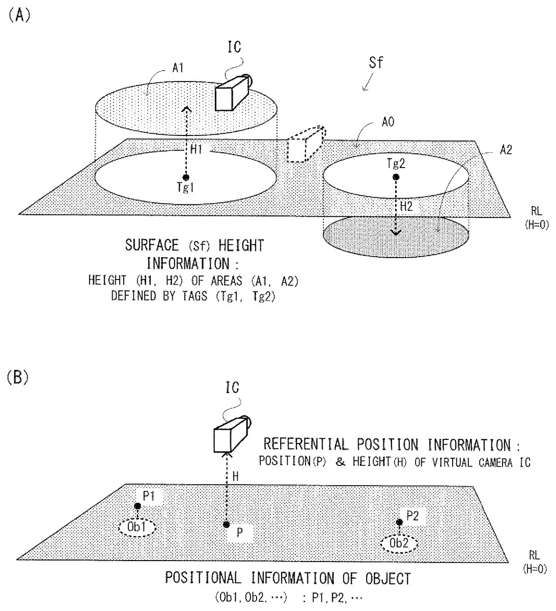
A description is next made focusing on the features. The ground of the virtual space IS is made up of a level ground LG, a cliff C1, a valley V1, etc. as shown inFIG. 10, and a base Bs is set on the level ground LG. The virtual camera IC, that is, the player character dowses the object (Ob1, Ob2, . . . ), such as coins, buried underground with the sword Sw while moving up and down on the ground and the base Bs (hereinafter, referred to as “surface”). At this time, the viewpoint, that is, the height of the virtual camera IC changes along the surface Sf defined as shown inFIG. 14(A), for example.
Referring toFIG. 14(A), the surface Sf roughly represents the virtual space IS shown inFIG. 10by a reference level RL and tags Tg1, Tg2, . . . provided thereon. The reference level RL corresponds to a level ground LG, for example, and the height shall be “0”. In each tag Tg1, Tg2, . . . , the center, the radius and the height are described. Accordingly, the respective tags Tg1, Tg2, . . . represent circle areas A1, A2, . . . respectively corresponding to a cliff C1and a valley V1and the height H1, H2, . . . thereof. Here, the information representing the surface Sf in such a manner is displayed as surface height information78inFIG. 13.
On the other hand, the position and the optical axis direction (the direction of the glance) of the virtual camera IC (player character) are controlled according to an operation by the controller14(first controller34and second controller36). On the game screen, icons of the first and second controllers (34and36) and icons Ic1and Ic2indicating the functions thereof, an icon Sh indicating the function set to the “-” button of the second controller34are translucently displayed on the virtual space image (IS).
The icon Ic1indicates the change of the optical axis direction of the virtual camera IC in correspondence with the direction of the first controller34. The icon Ic2indicates the change of the position of the virtual camera IC in accordance with the operation with the second controller34. The icon Sh in association with the “-” button of the controller34indicates that a dowsing ability capable of detecting a specific kind of the object is given to the sword Sw. Here, the division of the function between the first controller34and the second controller36is one example and is appropriately changed.
The dowsing ability (kind of the detectable object) to be given to the sword Sw can arbitrarily be selected through the game screen shown inFIG. 9. On the game screen, eight icons Sh representing various objects, such as gold coins and items are shown. When the player selects one of them (icon Sh representing a gold coin, for example), the selected icon. Sh is brought into association with the “-” button of the controller34as shown inFIG. 10toFIG. 12.
Thus, the dowsing ability capable of detecting a gold coin is applied to the sword Sw. Hereafter, the player can perform dowsing with the sword Sw by pushing the “-” button when he or she wants to search for a gold coin. However, such a button operation is one example and can arbitrarily be changed.
During dowsing, the virtual camera IC moves in an arbitrary direction along the surface Sf shown inFIG. 14(A). The height H (seeFIG. 14(B)) of the virtual camera IC changes at a timing when the virtual camera IC crosses over the border between the area A0and A2, and the detection range DA changes in correspondence with the height H of the virtual camera IC at this point as shown inFIG. 15, for example.
That is, in a case that the virtual camera IC is positioned within the area A0(the player character is on the level ground LG), the height H of the virtual camera IC is “0”, and “normal” is used as a reference detection range DA. Thereafter, when the virtual camera IC enters the area A1(the player character climbs the cliff C1), the height H of the virtual camera IC changes (increases) from “0” to “H1”, and the detection range DA is enlarged from “normal” to “long&wide”. On the other hand, when the virtual camera IC enters the area A2(the player character goes down to the valley V1), the height H of the virtual camera IC changes (decreases) from “0” to “H2”, and the detection range DA is reduced from “normal” to “short&narrow”. Thus, when the height of the virtual camera is high, a good view of surrounding is offered, so that the detection range is set to be large, and when the height of the virtual camera is low, a poor view is offered, so that the detection range is set to be small, capable of presenting a realistic search to the player.
Here, the initial value (called “basic detection range”) of the detection range DA is “normal” in this embodiment, but in a modified example, “long&wide” and “short&narrow” may be set in correspondence with the attribute of the detection object. For example, if the object to be detected is a moving object, such as “animals”, it is difficult to detect it, and thus by setting “long&wide” as an initial value, the object is made easily detectable, capable of properly setting the difficulty level of the game. Also, if the object to be detected is a rare object, such as “diamonds”, by setting “short&narrow” as an initial value, the object is made hardly detectable, capable of giving the player a feeling of accomplishment when this is searched. The typical attributes also include a size other than the movement and the rarity. For example, because the larger object is easily found, the detection range is set to be large. Such a control of the detection range DA based on the attribute is typically executed at the initial setting, but may suitably be executed during dowsing without being restricted thereto.
Furthermore, the change of the detection range DA is based on both of the distance d and the angle θ in this embodiment, but only any one of them may be changed. In addition, whether both of the distance d and the angle θ are changed, only the distance d is changed, or only the angle θ is changed may be decided on the basis of the attribute of the object to be detected.
If there are a plurality of objects to be detected within the detection range DA, one of them is decided as a top-priority object according to the procedure shown inFIG. 16, for example. The top-priority object here is an object for which the strength of the detection by dowsing becomes maximum, and the sword Sw responds to the top-priority object. Accordingly, the pointer Pnt is positional relationship information visually representing a positional relationship between the virtual camera IC and the top-priority object.
The strength of the detection is calculated based on the positional relationship between the virtual camera IC and each object, that is, based on the distance d and the angle θ. In calculation, the distance d has priority over the angle θ. Which one is the top-priority object out of the plurality of objects within the detection range DA is basically decided by first comparing the distances d between the objects, and by further comparing the angles θ if there are objects having the same distance from the virtual camera IC. It should be noted that if two objects to be detected are placed at positions symmetric with respect to an optical axis, the objects exceptionally have the same distance and the same angle, and in such a case, an arbitrary one may be selected.
For example, as shown inFIG. 16(A), in a case that five objects to be detected (objects Ob1-Ob5) are present around the optical axis (glance) of the virtual camera IC, the objects Ob4, Ob5positioned out of the detection range DA are excluded form the candidates (d4>dmax, θ5>θmax). Among the objects Ob1-Ob3within the detection range DA, the objects Ob1, Ob2having smaller distances d have priority (d1=d2<d3). Between the objects Ob1, Ob2having the same distance, the object Ob2having a smaller angle θ has top priority (θ2dmax, that is, the virtual camera IC and the target object Obi are far from each other, the pointer Pnt is fixed to a state of “white & absence of the prickle”. Here, in a case of θi>θmax as well, the pointer Pnt is fixed to the state of “white & absence of the prickle”.
If the virtual camera IC and the target object Obi are close to each other to satisfy di=dmax, the pointer Pnt which had been a simple white circle until now changes to pale blue, and has a small prickle. In a case of di<dmax, the shorter the distance di is, the deeper blue the pointer Pnt is in color, and the larger the prickle is. Such a change may be made continuously or step by step.
In a case that the manner of the pointer Put (color and size of the prickle) are changed step by step, the detection range DA is sectioned into a plurality of areas (three area B1, B2, B3respectively corresponding to three sections 0<di≦20, 20<di≦50, 50dmax or θ i>θ max) of the detection range DA (“white & absence of the prickle” and “colored & presence of the prickle”), and further changing continuously or step by step the depth of the color and the size of the prickle in correspondence with the distance di within the detection range DA, it is possible to visually present the player character, that is, the positional relationship between the virtual camera IC and the target object Obi.
Here, the positional relationship may be presented in a tactile or audible manner as shown inFIG. 19through vibrations of the controller14and a search sound from the speaker30, for example, as well as be visually presented through the pointer Pnt. More specifically, outside the detection range DA, the vibration is fixed to the weakest state, and the search sound is fixed to a late periodical sound “PE . . . PE . . . ”.
Into the detection range DA from the outside, the vibrations change from the weakest state to a weak, medium or strong state, and the search sound changes from the late periodical sound “PE . . . PE . . . ” to a slow periodical sound “PE.PE.PE.”, a moderate periodical sound “PePePe” or a fast periodical sound “PPPPPPP”. Which strength and velocity the vibrations and the search sound are changed to is dependent on the distance di at a time of entering the detection range DA. For example, when the angle θi is decreased over the θmax, if di=50, the vibrations change from the weakest state to the medium state, and the search sound changes from the late periodical sound “PE . . . PE . . . ” to the moderate periodical sound “PePePe”. Although the description is omitted in the above, the changes of the pointer Pnt at this point are a change from “white & absence of prickle” to “normal blue and medium prickle”.
Within the detection range DA, as the distance di is decreased, the strength of the vibration (amplitude and/or cycle) is increased, such as weak→medium→strong, and the cycle of the search sound is increased as in “PE.PE.PE.”→“PePePe”→“PPPPPP”. In a case of being out of the detection range DA from the inside or in a case that the distance di is increased within the detection range DA, reciprocal changes thereof occur.
Here, in place of changing the cycle of the search sound, or in addition thereto, a cycle of emission of the LED84may be changed.
The image processing as described above is implemented by executing flowcharts shown inFIG. 20toFIG. 22by the CPU40in cooperate with the system LSI42on the basis of programs and information (various parameters, variables, input and output data) shown inFIG. 13which are stored in the main memory42eand/or46.
In the main memory42eand/or46, a program area70, a parameter area76, a variable area82, an input area92and an output area94are formed, and in the program area70, a game program72, an input-output controlling program74, etc. are stored as shown inFIG. 13.
The game program72is a main software program for implementing the dowsing game by controlling the entire hardware (seeFIG. 2) of the game apparatus12via the CPU40. The game program72includes an image processing program72acorresponding to the flowcharts inFIG. 20toFIG. 22as a sub software program. The image processing program72aimplements the image processing as described above in corporate with the input-output controlling program74under the control of the game program72.
The input-output controlling program74controls an output of the game image depicted in the VRAM42dmainly to the monitor28and an input of control data from the controller14(to the input area92described later) via the input-output processor42a(through the output area94described later). Although illustration is omitted, the processing by the input-output controlling program74is simultaneously executed in parallel with the image processing inFIG. 20toFIG. 22.
In the parameter area76, surface height information78and object information80are stored. The surface height information78is information representing the height of the surface (Sf: seeFIG. 14(A)) of the virtual space IS by using the Tg1, Tg2, . . . arranged on the reference level RL (height0). In the tag Tg1, information indicating the center, the radius and the height is described, and in the tag Tg2, similar information is described. The circle areas A1and A2defined by such tags Tg1, Tg2respectively correspond to the cliff C1and the valley V1in the virtual space IS inFIG. 10. The area A0is a remaining area exclusive of the areas A1, A2, . . . from the reference level RL, and corresponds to the level ground LG in the virtual space IS inFIG. 10.
Here, the area defined by the tag may take a shape except for a circle, such as an oval figure, a polygon, etc. If a plurality of tags different in shape are combined, the surface Sf with more complex concaves/convexes can be represented. Furthermore, the surface height information78may be added to image data, such as a polygon, a texture, etc. independent of the tags.
The object information80is information describing the position (P1, P2, . . . ) and the kind (gold coins, items, animals, etc.), and a target flag indicating whether an object to be searched or not, with respect to each object (Ob1, Ob2, . . . ) arranged within the virtual space IS. Each of the target flags is turned off at an initial state, and switched between ON and OFF for each kind in response to an operation on the selection screen shown inFIG. 9. For example, in a case that three gold coins (Ob1to Ob3) are hidden within the virtual space IS, when a gold coin is selected on the selection screen, the target flag of the objects Ob1to Ob3corresponding to each of the gold coins is switched from OFF to ON. Here, in a case that the basic detection range is set in correspondence with the attribute of the object to be detected (see step S20inFIG. 21), the attribute (move/not move, for example) of each object Ob1, Ob2, . . . is also described.
In the variable area82, referential position information84, detection range information86, object information88and positional relationship information90are stored. The referential position information84is information indicating the position and height (H) of the virtual camera IC (P) at this point as shown inFIG. 14(B). The virtual camera IC moves along the surface Sf (seeFIG. 14) of the virtual space IS, and thus the height H changes among the heights0, H1, H2, . . . depending on which area A0, A1, A2, . . . the position P belongs to as shown inFIG. 14(A).
The detection range information86is information indicating a range capable of detection by dowsing at this point, and specifically represents a cone-shaped detection range DA taking the virtual camera IC as a base point as shown inFIG. 16(B). The detection range DA is defined by the threshold value dmax relating to the distance d and the threshold value θmax relating to the angle θ. In the threshold value dmax and θmax, the value corresponding to the height H of the virtual camera IC (=0, H1, H2) is set as shown inFIG. 15(H1is a positive value, H2is a negative value, here). For example, 100 m and 15 degrees are set as values for normal when H=0, 1000 m and 20 degrees are set as values for long&wide when H=H1, and 20 m and 10 degrees are set as values for short&narrow when H=H2. Here, the extent of the detection range DA is changed in three levels, but it may be set in two levels or four or more levels. Also, the values of the threshold value dmax and θmax are merely one example and may suitably be changed.
The object information88is information indicating an object Obi to be dowsed at this point, that is, information indicating the object to which the sword Sw responds, and is represented by the distance (di) and the direction (θi) relating to the object Obi. During dowsing, in a case that a single object to be detected exists within the detection range DA, the single object to be detected is set to the object Obi, and in a case that a plurality of objects to be detected exist within the detection range DA, a top-priority object (seeFIG. 16) decided based on the strength of the detection out of the plurality of objects to be detected is set. Here, in a case there is no object to be detected within the detection range DA, “null” is described.
The positional relationship information90is information indicating a manner of the pointer Pnt, specifically, indicating the color and the size of the prickle. The color and the size of the prickle change mainly in correspondence with the distance di (the detail is as described above) as shown inFIG. 17. Here, in the positional relationship information90, information for controlling the position and the direction of the pointer Pnt (seeFIG. 11andFIG. 12) on the game screen is also added.
In an input area92, controller data input from the controller14is stored. In an output area94, game image data to be output to the monitor28through the VRAM42dis stored.
Here, the aforementioned contents stored in the parameter area76are set at the beginning of dowsing. The contents stored in the variable area82, the input area92and the output area94are initialized at the beginning of dowsing, and updated every frame (at a cycle of 1/60 sec. for example) during dowsing.
When the game program72is activated, the CPU40first executes initial processing in a step S1. In the initial processing, initialization of the VRAM42dand generation of game image data are performed. After completion of the initial processing, the CPU40executes any one of loop processing of four kinds such as from step S3through any one of steps S5, S11, S15and S17to the step S3for each frame.
In the step S3, writing game image data to the output area94is performed. Immediately after the activation, the initial game image data generated in the step S1is written. The game image data written to the output area94is transferred to the VRAM42dunder the control of the input-output controlling program74, and a game image based thereon is displayed on the monitor28.
In the step S5, it is determined whether or not controller data is input to the input area92, and if “NO”, the process returns to the step S3to perform writing the game image data at a timing of a next frame. If “YES” in the step S5, the process proceeds to a step S7to determine whether or not end instruction is included in the controller data. If “YES” in the step S7, the dowsing game is ended.
If “NO” in the step S7, the process proceeds to a step S9to determine whether or not the current scene is a dowsing scene. Here, the information relating to the current scene is under the control of the game program72, and for the determination in the step S9, the information is referred. If “NO” in the step S9, that is, if the current scene is a scene except for the dowsing scene, another image processing is executed in the step S11, and the process returns to the step S3to repeat the processing similar to the above description. In the current step S3, the game image data after the image processing in the step S11is written to the output area94, and based thereon, the contents stored in the VRAM42dand the contents displayed on the monitor28are updated.
If “YES” in the step S9, that is, if the current scene is a dowsing scene, the process proceeds to a step S13to determine whether or not the object to be detected has already been selected, and if “NO” here, the process proceeds to the step S15. In the step S15, an object selecting screen is generated so as to be displayed on the game image. Thus, a game screen for selecting an object as shown inFIG. 9is displayed on the monitor28. On the game screen, eight icons Sh representing various objects, such as gold coins and items are depicted. Thereafter, the process returns to the step S3to repeat the processing similar to the above description. The loop processing being made up of the steps S3to S9, S13and S15is repetitively executed until any one of the icons is selected by the controller14.
When an operation of selecting any one of the icons Sh is performed on the game screen inFIG. 9, the result of the selection is reflected on the controller data of the input area92, and the determination result in the step S13changes from “NO” to “YES”. If “YES” in the step S13, it is determined whether or not this point in time is a start of the dowsing scene in a step S16a, and if “NO” here, the process proceeds to the step S17.
If “YES” in the step S16a, setting the parameters and initializing the variables are performed in a step S16b, and the results are written to the parameter area76as surface height information78and object information80. The target flag included in the object information80is turned on as to the object (one or plurality) corresponding to the selected icon Sh (gold coin, for example), and is turned off as to the other objects. Then, the process proceeds to the step S17.
The in the step S17, dowsing image processing (seeFIG. 21andFIG. 22) is executed. Although the detailed description is made later, in the dowsing image processing, a series of processing of generating an image of the pointer Pnt indicating the result of the dowsing and depicting the generated pointer image (Pnt) on the game image is executed on the basis of the contents stored in the parameter area76and the variable area82. Then, the process returns to the step S3to repeat the processing similar to the above description.
Thus, the game screen shown inFIG. 10toFIG. 12is displayed on the monitor28. On the game screen, the target object Obi is hidden underground, and the position P of the player character (virtual camera IC) which performs dowsing with the sword. Sw is moved in accordance with an operation with the controller14. The pointer image (Pnt) on the game screen indicates the positional relationship between the player character (virtual camera IC) and the target object Obi (seeFIG. 14(B)).
The loop processing being made up of the steps S3to S9, S13, S16a, S16band S17is repetitively executed until end processing is performed by the controller14(or an end event, such as game over, etc. not shown occurs).
The dowsing image processing in the aforementioned step S17is specifically executed according to the flowcharts shown inFIG. 21andFIG. 22. Referring first toFIG. 21, in a step S21, it is determined whether or not the virtual camera IC moves on the basis of the controller data of the input area92, and if “NO”, the process proceeds to a step S29. If “YES” in the step S21, the referential position information84of the variable area82is updated in a step S23.
More specifically, first, the position P (seeFIG. 14(B)) is updated to the latest value. Next, with reference to the surface height information78, an area (any one of A0, A1, A2, . . . ) to which the updated position P belongs is specified, and the height corresponding to the result of the specification (H1corresponding to A1, for example) is obtained, and the height H is updated by the obtained value. Accordingly, in this embodiment, the time when the height H described in the referential position information84changes is restricted to a case that the virtual camera IC moves over the border between the areas A0, A1, A2, . . . . Then, the process proceeds to a step S25.
In the step S25, it is determined whether or not the height H changes, and if “NO”, the process proceeds to the step S29. If “YES” in the step S25, the detection range information86of the variable area82is updated in a step S27. More specifically, from among three different combinations (normal, long&wide, short&narrow), the dmax and the θmax (long&wide corresponding to H1, for example) corresponding to the height H as shown inFIG. 15are selected, and the previously selected value described in the detection range information86is updated by the currently selected value. Then, the process proceeds to the step S29.
It should be noted that directly before the step S21, depending on the attribute of the object to be detected, a step S20of adding the basic detection range may be added. The step S20is executed once directly after the start of the dowsing image processing. Thereafter, the enlargement/reduction of the detection range DA in correspondence with the height H to be executed for every frame in a step S27is executed by taking the basic detection range set in the step S20as an initial value. In the object information80(seeFIG. 13), an attribute of each of the objects Ob1, Ob2, . . . is further described, and the attribute described in the object information80is referred for setting. In the example shown inFIG. 13, the attribute of the object (Ob1, Ob2) for which the target flag is turned on is “not moving”, and thus, the basic detection range is set to the normal.
In a step S29, it is determined whether or not an object to be detected (object for which the target flag is turned on) exists within the detection range DA on the basis of the object information80, the referential position information84and the detection range information86. If “NO” here, “white & absence of prickle” is written to the positional relationship information90in a step S31, and then, the process proceeds to a step S43.
If “YES” in the step S29, the process shifts to a step S33to further determine whether or not an object to be detected existing within the detection range DA is a single, and if “YES”, the process proceeds to a step S37. If “NO” in the step S33, the top-priority object is decided in a step S35, and the process proceeds to the step S37. The top-priority object deciding processing in the step S35is executed according to the flowchart shown inFIG. 22, for example.
With reference toFIG. 22, in a first step S51, an initial value “1” is set to the variable i, and one object to be detected is selected from a plurality of objects to be detected. Next, in a step S53, it is determined whether or not the distance di to the selected object to be detected is a minimum value among the distances with the respective object to be detected. Then, if “YES” in the step S53, the process proceeds to a step S55while if “NO”, the process proceeds to a step S61.
In the step S55, it is further determined whether or not there is another object having the same distance di. If “YES” in the step S55, the process proceeds to a step S57while if “NO”, the process proceeds to a step S59.
In the step S57, it is further determined whether or not the angle θi of the selected object to be detected is larger than the angle of another object to be detected determined in the step S55. If “YES” in the step S57, the process proceeds to the step S61while if “NO”, the process proceeds to the step S59.
In the step S59, the object Obi is decided as a top-priority object, and then, the process returns to the hierarchical upper flowchart (seeFIG. 21). In the step S61, the variable i is incremented, and then, the process returns to the step S53to repeat the same processing similar to the above description. That is, the processing of selecting another object to be detected and determining whether the top-priority object or not is repeated.
Accordingly, as shown inFIG. 16, in a case that there are three objects to be detected (Ob1-Ob3) within the detection range DA, i=1 in the step S51, and then, it is determined whether or not the distance d1is a minimum value out of d1to d3in the step S53. In the example inFIG. 16, d1=d2θ2, the determination result in the step S57is “YES”. Thus, after i=2 in the step S61, the processing from the step S53onward is executed.
Because d2=d1<d3, the determination result in the step S53is also “YES” at this time, and the determination result in the step S55is also “YES”. However, because θ2<θ1, the determination result in the step S57is “NO”, and the object Ob2is decided as a top-priority object.
Here, inFIG. 16example, assuming that d1=d2<d3and θ1=θ2, the determination result in the step S57is “NO” at a time when i=1, and the object Obi is decided as a top-priority object. That is, the object checked first is a top-priority object.
Returning toFIG. 21, in the step S37, the object Obi (if only one object to be detected exists within the detection range DA, this is the single object, and if a plurality of objects to be detected exist, this is the top-priority object decided in the step S35), the distance di and the angle θi are written to the object information88. In a next step S39, the strength of the detection as to the object Obi is calculated on the basis of the object information88. Then, in a step S41, the color and the size of the prickle are calculated depending on the strength of the detection, and the result of the calculation is written to the positional relationship information90. Then, the process proceeds to a step S43. Here, the strength of the detection and the calculation method of the color and the size of the prickle depending on the strength of the detection are described before and thus omitted here.
In the step S43, the pointer image (Pnt) is depicted on the game image on the basis of the positional relationship information90. At this time, the depicting position of the pointer image (Pnt) (moreover, the position of the virtual camera IC) is controlled on the basis of the direction of the first controller34. Furthermore, as to the direction of the pointer Pnt, the prickle is controlled to direct to this object Obi. These controls are not the main features of this embodiment, and thus detailed explanations are omitted. Thereafter, the process returns to the hierarchical upper flowchart (seeFIG. 20). Thus, the game image data on which the depicting processing of the pointer image (Pnt) is performed is written to the output area94in the next step S3, and the game screen based thereon is displayed on the monitor28.
As understood from the above description, in the game system10of this embodiment, the CPU40of the game apparatus12writes a game image obtained by imaging the virtual space IS where an object (object Obi) is arranged with the virtual camera IC into the output area94of the main memories42e,46(S3), and depicts positional relationship information (image of the pointer Pnt) indicating a positional relationship between a predetermined referential position, for example, the position (P) of the virtual camera IC and the arrangement position (Pi) of the object on the game image stored in the output area90(S43). Then, the positional relationship information (Pnt) is changed in accordance with the conditions, such as the height H of the virtual camera IC from the reference level RL, and the attributes (moving/not moving) set to the object (S29, S31, S41). The positional relationship information is thus changed according to the conditions to thereby dynamically send a notice of the positional relationship information according to the situations of the referential position and the attributes of the object. Accordingly, it is possible to heighten the degree of flexibility of the game design.
Also, the CPU40sets the detection range DA (∂max, dmax) capable of detecting existence of the object, and changes the detection range DA depending on at least the height H (S20to S27). The positional relationship information indicates at least whether or not the arrangement position of the object is within the range with respect to the referential position.
Furthermore, the detection range DA is set on the basis of the distance (dmax) from the referential position and the direction (θmax), and is enlarged as the value indicated by the height H is large (seeFIG. 15).
Additionally, the positional relationship information indicates the strength of the detection of the object, and the detection range DA is divided into the plurality of areas (B1to B3) such that the strength of the detection is changed step by step within the range.
Also, the CPU40calculates the strength of the detection on the basis of the distance (di) from the referential position to the arrangement position of the object and the direction (θi) (S39), and changes the positional relationship information on the basis of the calculation result in a case that the arrangement position of the object is within the range with respect to the referential position. Then, the calculation is performed as to the distance in preference to the direction. More specifically, the calculation is performed based on the distance, and if the distance is equal to each other, the direction is taken into consideration. However, there is no need of being restricted thereto, and the calculation may be performed in a calculating method of assigning weights to the distance rather than the direction, for example.
Also, in a case that a plurality of objects (Ob1, Ob2, . . . ) exist within the range, the CPU40decides the top-priority object (Obi) on the basis of the distance (d1, d2, . . . ) from the referential position to each object and the direction (θ1, θ2, . . . ) (S35). The positional relationship information indicates the relationship with the top-priority object. The decision is also performed by giving a high priority to the distance than to the direction. More specifically, the decision is performed based on the distance, and if the distance is equal to each other, the direction is taken into consideration. There is no need of being restricted thereto, and the decision may be performed according to the algorithm of assigning weights to the distance rather than the direction, for example.
The detection range DA is also enlarged when the object moves (S20). It is preferable that it is more enlarged as the object is an object moving larger (faster). In the attribute, the information relating to a size is included, and if the size of the object is large, the detection range DA is enlarged so as to make it easy to find the object. It is preferable that as the object is larger in size, the detection range DA is enlarged. In the attribute, the information relating to rarity is included, and in a case that the rarity of the object is high, the range may be reduced to make it difficult to find the object. More preferably, the range is made narrow as the object is an object high in rarity.
Furthermore, each modified example described below is also possible.
The detection range DA changes depending on the height H of the virtual camera IC, that is, the local height (H1, H2, . . . ) of the surface Sf in this embodiment (seeFIG. 14(A)), but this may be changed over the entire area (stage) without being restricted thereto. For example, in the area of the sky or the sea, the detection range DA is set so as to be larger than that in the ground area to make it easy to search for an object even in the wide area.
The detection range DA is set with reference to the virtual camera IC, but may be set with reference to the sword Sw.
The distance di from the virtual camera IC to the object Obi is represented by a distance component along the optical axis direction, but may be represented by the length of the line segment connecting both of them.
The local height H1, H2, . . . of the surface Sf is described in the surface height information78in association with the tags Tg1, Tg2, . . . (seeFIG. 13,FIG. 14(A)) arranged in the map (reference level RL) but may be imbedded in the game image data (polygon data texture data, for example). Or, the map is divided into a plurality of areas to each of which the height may be set.
In the above description, the game apparatus12executing the game processing and the game system10including it are described, but these example embodiments of invention may also be applied to other image processing apparatuses or image processing systems in addition to other game apparatuses or game systems. In the game system or the image processing system, image processing may distributedly be performed by a plurality of computers, etc.
Although example embodiments of the present invention has been described and illustrated in detail, it is clearly understood that the same is by way of illustration and example only and is not to be taken by way of limitation, the spirit and scope of the present invention being limited only by the terms of the appended claims.
Furthermore, it should be understood that overall the embodiment of the present invention, a representation of a singular form also includes a concept of the plural form unless otherwise stated. Accordingly, an article or an adjective in the singular (for example, “a”, “an”, “the”, etc. for English) also includes a concept of the plural form unless otherwise stated.
Claims
- A non-transitory storage medium storing an image processing program, wherein said image processing program causes a computer of an image processing apparatus to provide functionality comprising: outputting a virtual space image obtained by imaging a virtual space in which at least one object is arranged with a virtual camera;notifying positional relationship information indicating a positional relationship between a predetermined referential position within said virtual space and an arrangement position of said object within said virtual space;and setting a detection range of said object in the virtual space, the detection range based on at least height information defining a height of the predetermined referential position in the virtual space from a reference level in the virtual space.
- The non-transitory storage medium storing an image processing program according to claim 1 , wherein said positional relationship information is information at least indicating whether or not the arrangement position of said object is within said detection range.
- The non-transitory storage medium storing an image processing program according to claim 2 , wherein said detection range is enlarged as a value indicated by said height information is large.
- The non-transitory storage medium storing an image processing program according to claim 2 , wherein said detection range is set on the basis of a distance and a direction from said predetermined referential position.
- The non-transitory storage medium storing an image processing program according to claim 4 , wherein said positional relationship information includes information indicating strength of detection of said object, and said detection range is divided into a plurality of areas so as to change the strength of the detection step by step within said detection range.
- The non-transitory storage medium storing an image processing program according to claim 5 , wherein said image processing program causes said computer to provide further functionality comprising: calculating the strength of the detection on the basis of the distance from said predetermined referential position to the arrangement position of said object and the direction, and changing said positional relationship information on the basis of the calculated strength of the detection in a case that the arrangement position of said object is within said detection range.
- The non-transitory storage medium storing an image processing program according to claim 6 , wherein the calculation is made by giving a higher priority to the distance than to the direction.
- The non-transitory storage medium storing an image processing program according to claim 2 , wherein said image processing program causes said computer to provide further functionality comprising: deciding a top-priority object on the basis of the distance from said predetermined referential position to each object and the direction in a case that a plurality of objects exist within said detection range, and said object is said top-priority object.
- The non-transitory storage medium storing an image processing program according to claim 8 , wherein a decision is made on deciding the top-priority object by giving a higher priority to the distance than to the direction.
- The non-transitory storage medium storing an image processing program according to claim 2 , wherein said height information belongs to an attribute set to said object.
- The non-transitory storage medium storing an image processing program according to claim 10 , wherein said attribute set includes information indicating whether or not said object is a movable object.
- The non-transitory storage medium storing an image processing program according to claim 1 , wherein the positional relationship information is represented by at least one of an image, a voice, vibrations or light emission.
- The non-transitory storage medium storing an image processing program according to claim 12 , wherein the positional relationship information is depicted as being indicated by the image on said virtual space image.
- The non-transitory storage medium storing an image processing program according to claim 13 , wherein the image representing the positional relationship information is controlled so as to be directed to said object.
- The non-transitory storage medium storing an image processing program according to claim 12 , wherein said image processing program causes said computer to provide further functionality comprising controlling the position of said virtual camera on the basis of an input from a pointing device.
- An image processing apparatus, comprising a processor system for: outputting a virtual space image obtained by imaging a virtual space in which at least one object is arranged with a virtual camera;notifying positional relationship information indicating a positional relationship between a predetermined referential position within said virtual space and an arrangement position of said object within said virtual space;and setting a detection range of said object in the virtual space, the detection range based on at least height information defining a height of the predetermined referential position in the virtual space from a reference level in the virtual space.
- The image processing apparatus according to claim 16 , wherein said positional relationship information is information at least indicating whether or not the arrangement position of said object is within said detection range.
- An image processing method to be executed by an image processing apparatus, including: outputting a virtual space image obtained by imaging a virtual space in which at least one object is arranged with a virtual camera;notifying positional relationship information indicating a positional relationship between a predetermined referential position within said virtual space and an arrangement position of said object within said virtual space;and setting a detection range of said object in the virtual space, the detection range based on at least height information defining a height of the predetermined referential position in the virtual space from a reference level in the virtual space.
- The image processing method according to claim 18 , wherein said positional relationship information is information at least indicating whether or not the arrangement position of said object is within said detection range.
- An image processing system, comprising: a computer system, including at least one computer processor, the computer system being configured to: output a virtual space image obtained by imaging a virtual space in which at least one object is arranged with a virtual camera;notify positional relationship information indicating a positional relationship between a predetermined referential position within said virtual space and an arrangement position of said object within said virtual space;and set a detection range of said object in the virtual space, the detection range based on at least height information defining a height of the predetermined referential position in the virtual space from a reference level in the virtual space.
- The image processing system according to claim 20 , wherein said positional relationship information is information at least indicating whether or not the arrangement position of said object is within said detection range.
- An image processing system comprising: a computer system, including at least one computer processor, the computer system at least being configured to: output a virtual space image obtained by imaging a virtual space in which at least one object is arranged with a virtual camera;notify positional relationship information indicating a positional relationship between a predetermined referential position within said virtual space and an arrangement position of said object within said virtual space;and set a detection range of said object in the virtual space, the detection range based on at least height information defining a height of the predetermined referential position in the virtual space from a fixed reference level in the virtual space.
- The image processing system according to claim 22 , wherein said positional relationship information is information at least indicating whether or not the arrangement position of said object is within said detection range.
Disclaimer: Data collected from the USPTO and may be malformed, incomplete, and/or otherwise inaccurate.