U.S. Pat. No. 9,387,398
VIDEO GAME WITH STATE DISPLAY OVERLAY
AssigneeNintendo Co., Ltd.
Issue DateAugust 26, 2010
Illustrative Figure
Abstract
A first area and a second area are set in a virtual space. Then, based on first configuration information for configuring a first state of a game world, a first object to be placed in the first area is generated. In addition, a second object to be placed in the second area is generated based on second configuration information for configuring a second state different from the first state at a predetermined position in the virtual space to which the first configuration information is applied.
Description
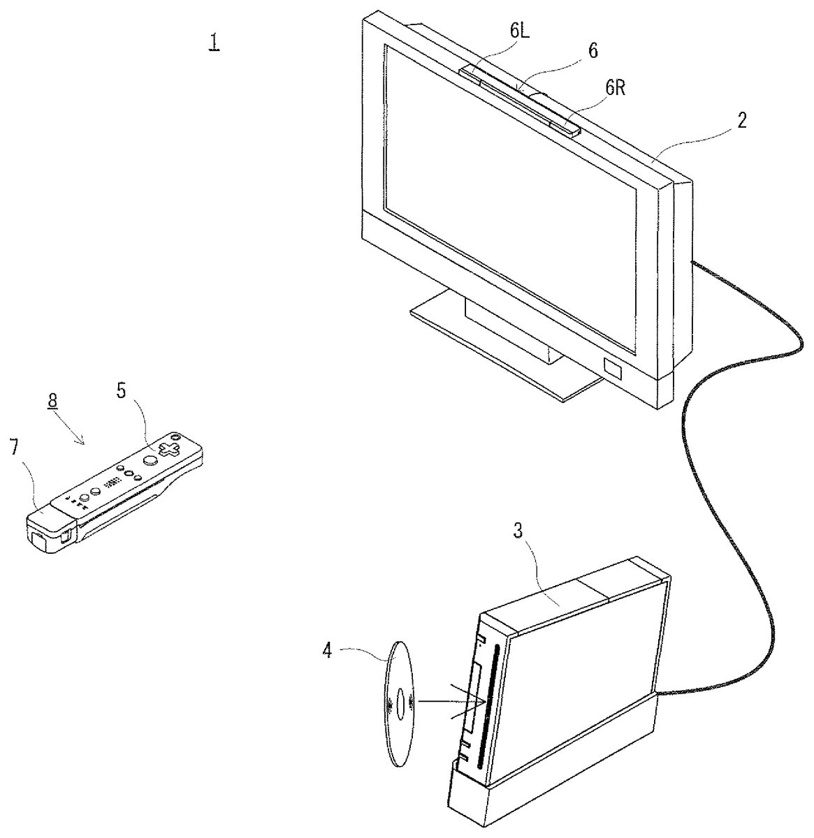
DESCRIPTION OF THE PREFERRED EMBODIMENTS The following will describe an embodiment of the present invention with reference to the drawings. It is noted that the present invention is not limited by the embodiment. [Whole Configuration of Game System] Referring toFIG. 1, a game system1including an example of a game apparatus according to the embodiment of the present invention will be described.FIG. 1is an external view of the game system1. Hereinafter, the game apparatus and a game program of the present embodiment will be described referring to a stationary game apparatus as an example. As shown inFIG. 1, the game system1includes a television receiver (hereinafter, referred to merely as a television)2, a game apparatus3, an optical disc4, an input apparatus8, and a marker section6. The game system1executes game processing on the game apparatus3in accordance with a game operation performed by using the input apparatus8. The optical disc4, which is an example of an information storage medium replaceably used with respect to the game apparatus3, is detachably inserted in the game apparatus3. The optical disc4stores a game program which is to be executed by the game apparatus3. The game apparatus3has an insertion slot for the optical disc4at the front surface of the game apparatus3. The game apparatus3reads and executes the game program stored in the optical disc4inserted in the insertion slot, thereby executing the game processing. The television2, which is an example of a display device, is connected to the game apparatus3via a connection cord. The television2displays game images which are obtained as the result of the game processing executed by the game apparatus3. In addition, the marker section6is mounted in the vicinity of the screen of the television2(inFIG. 1, on the upper surface of the screen). The marker section6has a marker6R and a marker6L at the respective ends of the marker ...
DESCRIPTION OF THE PREFERRED EMBODIMENTS
The following will describe an embodiment of the present invention with reference to the drawings. It is noted that the present invention is not limited by the embodiment.
[Whole Configuration of Game System]
Referring toFIG. 1, a game system1including an example of a game apparatus according to the embodiment of the present invention will be described.FIG. 1is an external view of the game system1. Hereinafter, the game apparatus and a game program of the present embodiment will be described referring to a stationary game apparatus as an example. As shown inFIG. 1, the game system1includes a television receiver (hereinafter, referred to merely as a television)2, a game apparatus3, an optical disc4, an input apparatus8, and a marker section6. The game system1executes game processing on the game apparatus3in accordance with a game operation performed by using the input apparatus8.
The optical disc4, which is an example of an information storage medium replaceably used with respect to the game apparatus3, is detachably inserted in the game apparatus3. The optical disc4stores a game program which is to be executed by the game apparatus3. The game apparatus3has an insertion slot for the optical disc4at the front surface of the game apparatus3. The game apparatus3reads and executes the game program stored in the optical disc4inserted in the insertion slot, thereby executing the game processing.
The television2, which is an example of a display device, is connected to the game apparatus3via a connection cord. The television2displays game images which are obtained as the result of the game processing executed by the game apparatus3. In addition, the marker section6is mounted in the vicinity of the screen of the television2(inFIG. 1, on the upper surface of the screen). The marker section6has a marker6R and a marker6L at the respective ends of the marker section6. Specifically, the marker6R (as well as the marker6L) has one or more infrared LEDs which output infrared light forward from the television2. The marker section6is connected to the game apparatus3, and the game apparatus3is capable of controlling illumination of each infrared LED of the marker section6.
The input apparatus8provides the game apparatus3with operation data which indicates contents of an operation made to the input apparatus8. In the present embodiment, the input apparatus8includes a controller5and a gyro sensor unit7. Though described in detail later, the input apparatus8is configured such that the gyro sensor unit7is connected to the controller5in a detachable manner. The controller5is connected to the game apparatus3by wireless communication. In the present embodiment, the technology of, for example, Bluetooth (registered trademark) is used for the wireless communication between the controller5and the game apparatus3. It is noted that in an alternative embodiment, the controller5may be connected to the game apparatus3via a wire.
[Internal Configuration of Game Apparatus3]
The following will describe an internal configuration of the game apparatus3with reference toFIG. 2.FIG. 2is a block diagram showing a configuration of the game apparatus3. The game apparatus3includes a CPU10, a system LSI11, an external main memory12, a ROM/RTC13, a disc drive14, an AV-IC15, and the like.
The CPU10executes the game processing by executing the game program stored in the optical disc4, and functions as a game processor. The CPU10is connected to the system LSI11. In addition to the CPU10, the external main memory12, the ROM/RTC13, the disc drive14, and the AV-IC15are connected to the system LSI11. The system LSI11performs processing such as control of data transfer between the system LSI11and each component connected to the system LSI11, generation of an image to be displayed, obtaining data from an external device, and the like. An internal configuration of the system LSI11will be described later. The volatile external main memory12stores a program such as the game program read from the optical disc4, a game program read from a flash memory17, and the like, and stores various data. The external main memory12is used as a work area and a buffer area for the CPU10. The ROM/RTC13includes a ROM (so-called boot ROM) that stores a program for starting up the game apparatus3, and a clock circuit (RTC: Real Time Clock) for counting time. The disc drive14reads program data, texture data, and the like from the optical disc4, and writes the read data into an internal main memory11edescribed later, or the external main memory12.
In addition, the system LSI11is provided with an input-output processor (I/O processor)11a, a GPU (Graphics Processor Unit)11b, a DSP (Digital Signal Processor)11c, a VRAM11d, and the internal main memory11e. Although not shown in the drawings, these components11ato11eare connected to each other via an internal bus.
The GPU11bforms a part of drawing means, and generates an image in accordance with a graphics command (command for generating graphics) from the CPU10. The VRAM11dstores data, such as polygon data and texture data, which are required for the GPU11bto execute the graphics command. Upon generation of an image, the GPU11dcreates the image data by using the data stored in the VRAM11d.
The DSP11cfunctions as an audio processor, and generates audio data by using sound data and sound waveform (tone color) data which are stored in the internal main memory11eor the external main memory12.
The image data and the audio data generated as described above are read by the AV-IC15. The AV-IC15outputs the read image data to the television2via an AV connector16, and the read audio data to speakers2abuilt in the television2. Thus, an image is displayed on the television2, and sound is outputted from the speakers2a.
The input-output processor11aperforms transmission and reception of data to and from each component connected to the input-output processor11a, and downloads data from an external device. The input-output processor11ais connected to the flash memory17, a wireless communication module18, a wireless controller module19, an extension connector20, and a memory card connector21. An antenna22is connected to the wireless communication module18, and an antenna23is connected to the wireless controller module19.
The input-output processor11ais connected to a network via the wireless communication module18and the antenna22, so that the input-output processor11ais communicable with another game apparatus connected to the network and various servers connected to the network. The input-output processor11aperiodically accesses the flash memory17to detect whether there are data needed to be transmitted to the network. If there is such data, the input-output processor11atransmits the data to the network via the wireless communication module18and the antenna22. In addition, the input-output processor11areceives data transmitted from the other game apparatus and data downloaded from a download server via the network, the antenna22, and the wireless communication module18, and then stores the received data in the flash memory17. The CPU10reads the data stored in the flash memory17by executing the game program, and uses the data for the game program. In addition to the data transmitted or received between the game apparatus3and the other game apparatus or various servers, the flash memory17may store saved data (result data or midstream data of the game) of the game played by using the game apparatus3.
In addition, the input-output processor11areceives operation data transmitted from the controller5, via the antenna23and the wireless controller module19, and stores (temporarily stores) the operation data in the buffer area of the internal main memory11eor the external main memory12.
In addition, the extension connector20and the memory card connector21are connected to the input-output processor11a. The extension connector20is a connector for an interface such as USB and SCSI. Instead of using the wireless communication module18, the extension connector20enables the communication with the network by connecting, to the extension connector20, a medium such as an external storage medium, a peripheral device such as another controller, or a wired connector for communication. The memory card connector21is a connector for connecting thereto an external storage medium such as a memory card. For example, the input-output processor11aaccesses the external storage medium via the extension connector20or the memory card connector21, thereby saving data in the external storage medium and reading data from the external storage medium.
The game apparatus3is provided with a power button24, a reset button25, and an eject button26. The power button24and the reset button25are connected to the system LSI11. When the power button24is turned on, electric power is supplied to each component of the game apparatus3via an AC adaptor (not shown). The reset button25is pressed to cause the system LSI11to restart a startup program of the game apparatus3. The eject button26is connected to the disc drive14. The eject button26is pressed to eject the optical disc4from the disc drive14.
[Configuration of Input Apparatus8]
Next, the input apparatus8will be described with reference toFIGS. 3 to 6.FIG. 3is a perspective diagram showing an external configuration of the input apparatus8.FIG. 4is a perspective diagram showing an external configuration of the controller5. The perspective view ofFIG. 3is seen from a top rear side of the controller5, and the perspective view ofFIG. 4is seen from a bottom front side of the controller5.
As shown inFIG. 3andFIG. 4, the controller5has a housing31formed by, for example, plastic molding. The housing31has a generally parallelepiped shape extending in a longitudinal direction (Z-axis direction shown inFIG. 3) from front to rear. The overall size of the housing31is small enough to be held by one hand of an adult or even a child. The player can perform a game operation by pressing a button provided to the controller5or moving the controller5to change the position or the attitude thereof.
A plurality of operation buttons are provided to the housing31. As shown inFIG. 3, there are provided, on the top surface of the housing31, a cross button32a, a first button32b, a second button32c, an A-button32d, a minus button32e, a home button32f, a plus button32g, and a power button32h. In the present specification, the top surface of the housing31on which the above buttons32ato32hare provided is sometimes referred to as a “button surface”. On the other hand, as shown inFIG. 4, a recessed portion is formed on a bottom surface of the housing31, and a B-button32iis provided on a slope surface at the rear of the recessed portion. Operation functions are appropriately assigned to the operation buttons32ato32iin accordance with the game program executed by the game apparatus3. In addition, the power button32his used for turning on or off the power of the game apparatus3by remote control. The home button32fand the power button32hhave top surfaces thereof buried in the top surface of the housing31. Thus, the player can be prevented from erroneously pressing the home button32for the power button32h.
On a rear surface of the housing31, a connector33is provided. The connector33is used for connecting another apparatus (for example, the gyro sensor unit7or another controller) to the controller5. In addition, latch dents33aare provided on the both sides of the connector33on the rear surface of the housing31. The latch dents33aprevent the other apparatus from being easily detached.
On the rear portion of the top surface of the housing31, a plurality of (four, inFIG. 3) LEDs34ato34dare provided. Here, a controller type (number) is assigned to the controller5such that the controller5is distinguishable from another main controller. The LEDs34ato34dare used for, for example, informing the player of the controller type which is currently set for the controller5, or for informing the player of remaining battery charge of the controller5. More specifically, when a game operation is performed by using the controller5, one of the plurality of LEDs34ato34dis lit up in accordance with the controller type.
The controller5has an imaging information calculation section35(FIG. 6), and a light incident surface35aof the imaging information calculation section35is provided on the front surface of the housing31, as shown inFIG. 4. The light incident surface35ais made of material allowing at least infrared light outputted from the markers6R and6L to pass through.
On the top surface of the housing31, a sound hole31afor externally outputting a sound from a speaker49(shown inFIG. 5) which is incorporated in the controller5is provided between the first button32band the home button32f.
Next, with reference toFIGS. 5 and 6, an internal structure of the controller5will be described.FIG. 5andFIG. 6are diagrams illustrating the internal structure of the controller5.FIG. 5is a perspective view illustrating a state where an upper housing (a part of the housing31) of the controller5is removed.FIG. 6is a perspective view illustrating a state where a lower housing (a part of the housing31) of the controller5is removed.FIG. 6is a perspective view illustrating a reverse side of a substrate30shown inFIG. 5.
As shown inFIG. 5, the substrate30is fixed inside the housing31, and on a top main surface of the substrate30, the operation buttons32ato32h, the LEDs34ato34d, an acceleration sensor37, an antenna45, the speaker49, and the like are provided. These elements are connected to a microcomputer42(seeFIG. 6) via lines (not shown) formed on the substrate30and the like. In the present embodiment, the acceleration sensor37is provided on a position offset from the center of the controller5with respect to the X-axis direction. Thus, calculation of the movement of the controller5being rotated around the Z-axis may be facilitated. Further, the acceleration sensor37is provided in front of the center of the controller5with respect to the longitudinal direction (Z-axis direction). Further, a wireless module44(seeFIG. 6) and the antenna45allow the controller5to act as a wireless controller.
On the other hand, as shown inFIG. 6, at a front edge of a bottom main surface of the substrate30, the imaging information calculation section35is provided. The imaging information calculation section35includes an infrared filter38, a lens39, the image pickup element40and an image processing circuit41located in order, respectively, from the front surface of the controller5. These components38to41are attached on the bottom main surface of the substrate30.
On the bottom main surface of the substrate30, the microcomputer42and a vibrator48are provided. The vibrator48is, for example, a vibration motor or a solenoid, and is connected to the microcomputer42via lines formed on the substrate30or the like. The controller5is vibrated by an actuation of the vibrator48based on a command from the microcomputer42. Therefore, the vibration is conveyed to the player's hand holding the controller5, and thus a so-called vibration-responsive game is realized. In the present embodiment, the vibrator48is disposed slightly toward the front of the housing31. That is, the vibrator48is positioned at the end portion of the controller5offset from the center thereof, and therefore the vibration of the vibrator48can lead to enhancement of the vibration of the entire controller5. Further, the connector33is provided at the rear edge of the bottom main surface of the substrate30. In addition to the components shown inFIGS. 5 and 6, the controller5includes a quartz oscillator for generating a reference clock of the microcomputer42, an amplifier for outputting a sound signal to the speaker49, and the like.
Further, the gyro sensor unit7includes a gyro sensor (gyro sensors55and56shown inFIG. 7) for detecting for angular velocities around three axes, respectively. The gyro sensor unit7is detachably mounted to the connector33of the controller5. The gyro sensor unit7has, at the front edge (an edge portion facing toward the Z-axis positive direction shown inFIG. 3), a plug (a plug53shown inFIG. 7) connectable to the connector33. Further, the plug53has hooks (not shown) on both sides, respectively. In a state where the gyro sensor unit7is mounted to the controller5, the plug53is connected to the connector33, and the hooks engage in the locking holes33a, respectively, of the controller5. Therefore, the controller5and the gyro sensor unit7are securely fixed to each other. Further, the gyro sensor unit7has a button51on each side surface (surfaces facing toward the X-axis direction shown inFIG. 3). When the buttons51are pressed, the hooks are disengaged from the locking holes33a. Therefore, when the plug53is removed from the connector33while the buttons51are being pressed, the gyro sensor unit7can be disconnected from the controller5.
Further, a connector having the same shape as the connector33is provided at the rear edge of the gyro sensor unit7. Therefore, another device which can be mounted to (the connector33of) the controller5can be mounted to the connector of the gyro sensor unit7. InFIG. 3, a cover52is detachably provided over the connector.
The shapes of the controller5and the gyro sensor unit7, a shape of each operation button, the number of acceleration sensors, the number of vibrators, fixing positions of the acceleration sensor and the vibrator, and the like shown inFIGS. 3 to 6are merely examples. The present invention can be realized by using other shapes, numbers, and fixing positions. Further, although in the present embodiment the imaging direction of the image pickup means is Z-axis positive direction, the imaging direction may be any direction. That is, the imagining information calculation section35(the light incident surface35aof the imaging information calculation section35) of the controller5may not be provided on the front surface of the housing31, but may be provided on any other surface on which a light can be received from the outside of the housing31.
FIG. 7is a block diagram illustrating a structure of the input device8(the controller5and the gyro sensor unit7). The controller5includes an operation section32(the respective operation buttons32ato32i), the connector33, the imaging information calculation section35, a communication section36, and the acceleration sensor37. The controller5transmits, as operation data, data representing a content of operation performed on the controller5itself, to the game apparatus3.
The operation section32includes the operation buttons32ato32idescribed above, and outputs, to the microcomputer42of a communication section36, operation button data indicating an input state (that is, whether or not each operation button32ato32iis pressed) of each operation button32ato32i.
The imaging information calculation section35is a system for analyzing image data taken by the image pickup means and calculating the centroid, the size and the like of an area having a high brightness in the image data. The imaging information calculation section35has, for example, a maximum sampling period of about 200 frames/sec., and therefore can trace and analyze even a relatively fast motion of the controller5.
The imaging information calculation section35includes the infrared filter38, the lens39, the image pickup element40and the image processing circuit41. The infrared filter38allows only infrared light to pass therethrough, among light incident on the front surface of the controller5. The lens39collects the infrared light which has passed through the infrared filter38so as to be incident on the image pickup element40. The image pickup element40is a solid-state imaging device such as, for example, a CMOS sensor or a CCD sensor, and receives the infrared light collected by the lens39, and outputs an image signal. The markers6R and6L of the marker section6provided near the display screen of the television2each includes an infrared LED for outputting infrared light forward from the television2. Therefore, the infrared filter38enables the image pickup element40to receive only the infrared light which has passed through the infrared filter38and generate image data, so that an image of each of the markers6R and6L can be captured with enhanced accuracy. Hereinafter, the image captured by the image pickup element40is referred to as a pickup image. The image data generated by the image pickup element40is processed by the image processing circuit41. The image processing circuit41calculates, in the pickup image, a position of an imaging subject (the marker6R and the marker6L). The image processing circuit41outputs data representing a coordinate point of the calculated position, to the microcomputer42of the communication section36. The data representing the coordinate point is transmitted as operation data to the game apparatus3by the microcomputer42. Hereinafter, the coordinate point is referred to as a “marker coordinate point”. The marker coordinate point changes depending on an orientation (angle of tilt) and/or a position of the controller5itself, and therefore the game apparatus3is allowed to calculate the orientation and the position of the controller5by using the marker coordinate point.
In another embodiment, the controller5may not necessarily include the image processing circuit41, and the controller5may transmit the pickup image as it is to the game apparatus3. At this time, the game apparatus3may have a circuit or a program, having the same function as the image processing circuit41, for calculating the marker coordinate point.
The acceleration sensor37detects for an acceleration (including gravitational acceleration) of the controller5, that is, detects for a force (including gravity) applied to the controller5. The acceleration sensor37detects a value of an acceleration (linear acceleration) in the straight line direction along the sensing axis direction, among accelerations applied to a detection section of the acceleration sensor37. For example, multiaxial acceleration sensor having two or more axes detects an acceleration of a component for each axis, as an acceleration applied to the detection section of the acceleration sensor. For example, three-axis or two-axis acceleration sensor may be of the type available from Analog Devices, Inc. or STMicroelectronics N.V. The acceleration sensor37is, for example, an electrostatic capacitance type acceleration sensor. However, another type of acceleration sensor may be used.
In the present embodiment, the acceleration sensor37detects a linear acceleration in three axis directions, i.e., the up/down direction (Y-axis direction shown inFIG. 3), the left/right direction (the X-axis direction shown inFIG. 3), and the forward/backward direction (the Z-axis direction shown inFIG. 3), relative to the controller5. The acceleration sensor37detects acceleration for the straight line direction along each axis, and an output from the acceleration sensor37represents a value of the linear acceleration for each of the three axes. In other words, the detected acceleration is represented as a three-dimensional vector (ax, ay, az) in an XYZ-coordinate system (controller coordinate system) defined relative to the input device8(controller5). Hereinafter, a vector representing components of the acceleration values detected for the three axes, respectively, by the acceleration sensor37is referred to as an acceleration vector.
Data (acceleration data) representing an acceleration detected by the acceleration sensor37is outputted to the communication section36. The acceleration detected by the acceleration sensor37changes depending on an orientation (angle of tilt) and a movement of the controller5, and therefore the game apparatus3is allowed to calculate the orientation and the movement of the controller5by using the acceleration data. In the present embodiment, the game apparatus3determines the orientation of the controller5based on the acceleration data.
The data (acceleration data) representing the acceleration (acceleration vector) detected by the acceleration sensor37is outputted to the communication section36. In the present embodiment, the acceleration sensor37is used as a sensor for outputting data to be used for determining the angle of tilt of the controller5.
When a computer such as a processor (for example, the CPU10) of the game apparatus3or a processor (for example, the microcomputer42) of the controller5processes an acceleration signal outputted from the acceleration sensor37, additional information relating to the controller5can be inferred or calculated (determined), as one skilled in the art will readily understand from the description herein. For example, suppose a case where the computer performs a process, based on the precondition that the controller5including the accelerate sensor37is in a static state (that is, a case where a process is performed based on the precondition that an acceleration detected by the acceleration sensor will include only a gravitational acceleration). When the controller5is actually in the static state, it is possible to determine whether or not the controller5tilts relative to the direction of gravity and to also determine a degree of the tilt, based on the acceleration having been detected. Specifically, when a state where a detection axis of the acceleration sensor37is toward the vertically downward direction represents a reference, whether or not the controller5tilts relative to the reference can be determined based on whether or not 1G (gravitational acceleration) is applied to the detection axis, and a degree to which the controller5tilts relative to the reference can be determined based on the magnitude of the gravitational acceleration. Further, the multiaxial acceleration sensor37subjects, to a processing, the acceleration signals having been detected in the respective axes so as to more specifically determine the degree to which the controller5tilts relative to the direction of gravity. In this case, the processor may calculate, based on the output from the acceleration sensor37, an angle of the tilt at which the controller5tilts, or calculate direction in which the controller5tilts without calculating the angle of the tilt. Thus, when the acceleration sensor37is used in combination with the processor, an angle of tilt or an orientation of the controller5may be determined.
On the other hand, in a case where it is anticipated that the controller5will be in a dynamic state (a state where the controller5is being moved), the acceleration sensor37detects an acceleration based on a movement of the controller5, in addition to the gravitational acceleration. Therefore, when the gravitational acceleration component is eliminated from the detected acceleration through a predetermined process, it is possible to determine a direction in which the controller5moves. Even when it is anticipated that the controller5will be in the dynamic state, the acceleration component based on the movement of the acceleration sensor is eliminated from the detected acceleration through a predetermined process, whereby it is possible to determine the tilt of the controller5relative to the direction of gravity. In another embodiment, the acceleration sensor37may include an embedded processor or another type of dedicated processor for performing, before outputting to the microcomputer42an acceleration signal detected by the acceleration detection means incorporated therein, any desired processing of the acceleration signal. For example, when the acceleration sensor37is intended to detect static acceleration (for example, gravitational acceleration), the embedded or dedicated processor could convert the acceleration signal to a corresponding angle of tilt (or another preferable parameter).
The communication section36includes the microcomputer42, a memory43, the wireless module44and the antenna45. The microcomputer42controls the wireless module44for wirelessly transmitting, to the game apparatus3, data acquired by the microcomputer42while using the memory43as a storage area in the process. Further, the microcomputer42is connected to the connector33. Data transmitted from the gyro sensor unit7is inputted to the microcomputer42through the connector33. Hereinafter, a structure of the gyro sensor unit7will be described.
The gyro sensor unit7includes the plug53, a microcomputer54, the two-axis gyro sensor55, and the one-axis gyro sensor56. As described above, the gyro sensor unit7detects angular velocities around three axes (XYZ axes in the present embodiment), respectively, and transmits data (angular velocity data) representing the detected angular velocities, to the controller5.
The two-axis gyro sensor55detects an angular velocity (per unit time) around each of the X-axis and the Y-axis. Further, the one-axis gyro sensor56detects an angular velocity (per unit time) around the Z-axis. In the present invention, directions of the rotations around the Z-axis, the X-axis, and the Y-axis relative to the imaging direction (the Z-axis positive direction) of the controller5are referred to as a roll direction, a pitch direction, and a yaw direction, respectively. That is, the two-axis gyro sensor55detects angular velocities in the roll direction (direction of rotation around the X-axis) and the pitch direction (direction of rotation around the Y-axis), and the one-axis gyro sensor56detects an angular velocity in the yaw direction (the direction of rotation around the Z-axis).
In the present embodiment, the two-axis gyro sensor55and the one-axis gyro sensor56are used so as to detect the angular velocities around the three axes. However, in another embodiment, the number of gyro sensors and a combination thereof to be used may be optionally selected provided that the angular velocities around the three axes can be detected.
Further, in the present embodiment, for the purpose of facilitating calculation, the three axes around which the gyro sensors55and56detect the angular velocities are set to correspond to three axes (XYZ-axes), respectively, for which the acceleration sensor37detects the accelerations. However, in another embodiment, the three axes around which the gyro sensors55and56detect the angular velocities need not correspond to the three axes for which the acceleration sensor37detects the accelerations.
Data representing the angular velocities detected by the gyro sensors55and56are outputted to the microcomputer54. Therefore, data representing the angular velocities around the three axes of the X, Y, and Z axes are inputted to the microcomputer54. The microcomputer54transmits the data representing the angular velocities around the three axes, as angular velocity data, to the controller5through the plug53. The transmission from the microcomputer54to the controller5is sequentially performed at a predetermined cycle, and the game is typically processed at a cycle of 1/60 seconds (corresponding to one frame time), and the transmission is preferably performed at a cycle shorter than a cycle of 1/60 seconds.
The controller5will be described again. Data outputted from the operation section32, the imaging information calculation section35, and the acceleration sensor37to the microcomputer42, and data transmitted from the gyro sensor unit7to the microcomputer42are temporarily stored in the memory43. The data are transmitted as the operation data to the game apparatus3. At a timing of the transmission to the wireless controller module19of the game apparatus3, the microcomputer42outputs the operation data stored in the memory43to the wireless module44. The wireless module44uses, for example, the Bluetooth technology to modulate the operation data onto a carrier wave of a predetermined frequency, and radiates the low power radio wave signal from the antenna45. That is, the operation data is modulated onto the low power radio wave signal by the wireless module44and transmitted from the controller5. The wireless controller module19of the game apparatus3receives the low power radio wave signal. The game apparatus3demodulates or decodes the received low power radio wave signal to obtain the operation data. Based on the obtained operation data and the game program, the CPU10of the game apparatus3performs the game process. The wireless transmission from the communication section36to the wireless controller module19is sequentially performed at a predetermined time interval. Since game process is generally performed at a cycle of 1/60 sec. (corresponding to one frame time), data is preferably transmitted at a cycle of a shorter time period. The communication section36of the controller5outputs, to the wireless controller module19of the game apparatus3, the respective operation data at intervals of 1/200 seconds, for example.
When the controller5is used, a player is allowed not only to perform a conventional typical game operation of pressing the respective operation buttons, but also to perform an operation of tilting the controller5at a desired angle of tilt. Other than these operations, by using the controller5, a player is allowed to perform an operation of designating a desired position on a screen, or perform an operation of moving the controller5itself.
Next, a summary of a game and processing to be executed in the present embodiment will be described. In the processing of the present embodiment, a virtual game world (hereinafter, simply referred to as a game world) which is a stage of the game is created in a virtual three-dimensional game space (hereinafter, simply referred to as a virtual game space). Two “world states” are defined for the virtual game world. The two “world states” are defined such that the respective contents of worlds in the two “world states” created in the same place in the virtual game space are different from each other, like a “present world” and a “past world”, for example. Examples of the contents of worlds to be created in a place include a state or an attribute of terrain, a virtual weather state, an appearance, a behavior, or an attribute of an object in the place. In the present embodiment, data for defining the two “world states” are prepared. Normally, a world based on data for a “first state” is created in the entire area of the virtual game space, and then the player progresses the game. Meanwhile, when a predetermined condition is satisfied during the game, a world based on data for a “second state” is created in a certain area of the virtual game space. That is, the game world becomes such that the “first state” and the “second state” are present at the same time in one virtual game space. In addition, a time limit during which the two world states are present at the same time is set. Moreover, in the present embodiment, processing is performed such that the two world states are displayed on the same game screen. That is, a game screen is generated such that the boundary between two areas of the two world states is included in the game screen. As a result, the player can progress the game while viewing the two world states. Thus, for example, by the world state varying as described above, it becomes possible to enter a place which the player has thought it impossible to enter, whereby unexpectedness of development of the game increases, and further, amusingness of the game increases.
Hereinafter, the above content will be described more specifically, with use of the drawings.FIG. 8is an example of a game screen assumed in the present embodiment. InFIG. 8, a game world created as a virtual three-dimensional space is displayed, and a player object101which is an object to be operated by the player is also displayed. In addition, a crystal object102is displayed in front of the player object101. In addition, a virtual camera, which is not shown, is basically placed in back of the player object101. The position and the like of the virtual camera are controlled such that the virtual camera follows the player object101.
The two “world states” as described above are set for the game world assumed in the present embodiment. Specifically, one is a “present world” and the other one is a “past world”. In addition, in the game of the present embodiment, the “present world” is set and defined as a wilderness world, and the “past world” is set and defined as a verdant world, in advance. Basically, the player progresses the game in a state where the “present world” is set as the stage of the game. That is, in a state shown inFIG. 8, the entirety of an area211of the game world displayed on the game screen is the “present world”. Note that a part of the area211corresponding to the “present world” is changed to the “past world” by the player performing a predetermined operation described below (or by a predetermined condition being satisfied).
Specifically, the crystal object102is a switch for changing a part of the area211. When the player has performed an operation of turning on the switch (hereinafter, referred to as a crystal switch) (e.g., when the player object101attacks or hits the crystal object102), an area221which is a part of the “present world” becomes the “past world”, as shown inFIG. 9. Here, setting of the game is such that the “past world” is “transferred” to the area221. Therefore, hereinafter, the area221is referred to as a transfer area221.FIG. 10andFIG. 11are schematic diagrams obtained by looking down upon states shown inFIG. 8andFIG. 9from above, respectively.FIG. 10corresponds to the states shown inFIG. 8, and the entirety of the area211in the game space is the “present world”. On the other hand,FIG. 11corresponds to the state shown inFIG. 9. The inside of the circular transfer area221is the “past world”, and the area211outside the circular transfer area221is the “present world”. That is, when the crystal switch is turned on, the circular transfer area221whose center (reference position) is at the position of the crystal object102is calculated, and the inside of the transfer area221is set as the “past world”. Then, the “past world” is created in the transfer area221. At this time, on the screen, the transfer area221is displayed by using an effect in which the transfer area221is circularly expanded to a predetermined size around the crystal object102. As a result, the “present world” and the “past world” are displayed at the same time on the game screen as shown inFIG. 9.
Here, since in the present embodiment, the virtual game space is created as a three-dimensional space, the “past world” is, to be exact, a dome-like space as shown inFIG. 12. However, for convenience of description, the following description always uses the expression “transfer area221” or “past world”, under the condition that the transfer area221(past world) includes a concept of such a three-dimensional space. Note that the “past world” (transfer area221) is not limited to a dome-like space as described above, and may be set as a cylindrical space.
As described above, when the crystal switch is turned on, a certain area (transfer area221) of the virtual game space is set as the “past world”, and a time limit during which the certain area is set as the “past world” is provided. For example, when ten seconds have passed after the crystal switch is turned on, the certain area set as the transfer area221is returned to the “present world”. At this time, the game screen displays the circular transfer area221reducing like being focused on the crystal object102. As a result, in the present embodiment, the transfer area221until disappearance from generation is depicted as follows, for example. First, when the crystal switch is turned on, the game screen displays a scene in which the transfer area221circularly expands and becomes a predetermined size in about one second. Thereafter, the size of the transfer area221does not vary for twenty seconds. When the twenty seconds have passed, the game screen displays a scene in which the transfer area221is reduced and disappears in about one second.
When the “present world” and the “past world” are present at the same time as described above, states or behaviors of objects other than the player object101, appearing in the virtual game space, are controlled so as to differ depending on whether the objects are present in the “present world” or in the “past world”. For example, in an example shown inFIG. 9, objects of plants which are not present in the “present world” appear in the transfer area221. That is, a display state (on/off) of an object differs between the “present world” and the “past world”.
As another example, a chicken object231is present in the “present world” as shown inFIG. 13. The chicken object231does not attack the player object101. On the other hand, when the crystal switch is turned on in the state inFIG. 13and a place where the chicken object231is present is set as the “past world”, the chicken object231changes to a monster object232as shown inFIG. 14. Moreover, the monster object232rushes at the player object101. That is, the appearance (state) of an object changes, and the behavior (action) of the object also changes.
In addition, as another example, a monster object of an insect type is depicted as an adult in the “present world”, and is depicted as a larva in the “past world”. In addition, in this case, the monster object may behave differently between an adult and a larva.
In addition, a state shown inFIG. 15is another example. InFIG. 15, a quicksand object233is placed in front of the player object101(that is, a part of a ground is quicksand). In the game, if the player object101enters the quicksand object233, the player object101sinks into the quicksand object. Therefore, in the state shown inFIG. 15, the player object101cannot be moved to the opposite side of the quicksand object233. Here, if a crystal switch present on the side of the player object101is turned on, a certain area whose center is at the position of the crystal object102is set as the transfer area221, that is, the “past world”, as shown inFIG. 16. As a result, the quicksand object233changes to a ground object on which the player object101can pass. Thus, it becomes possible to move the player object101forward. As described above, it is also possible to vary terrain between the “present world” and the “past world”.
In addition, a state shown inFIG. 17is another example. InFIG. 17, a construction object234is present in front of the player object101. The construction object234has a door235. The door235is present at a higher place than a place where the player object101is present. Therefore, in the state shown inFIG. 17, the player object101cannot enter the door235. Here, if a crystal switch near the player object101is turned on, a certain area is set as the transfer area221as shown inFIG. 18. Then, a stair object236which is not present in the “present world” appears in the transfer area221. As a result, it becomes possible to cause the player object101to climb the stair object236to reach the door235.
Other than the above, it is also conceivable to cause a “bridge object” which is not present in the “present world” to appear in the “past world”, as in the stair object236. That is, as an example, if a place which the player object101cannot pass is present in the “present world”, an area including the place is changed to the “past world” to allow the player object101to pass the place. In addition, other than this, for example, a case where an object has the same appearance but has different sizes between the “present world” and the “past world”, or a case where a robot object, an object such as “moving floor”, or the like which are deactivated in the “present world” are activated in the “past world”, is conceivable. In addition, for example, a case where a weather state varies like it is snowing in the “past world” but it is not snowing in the “present world”, or a case where an object displayed as a bone object (i.e., dead human) in the “present world” is displayed as an alive human object and can move around in the “past world”, is conceivable.
In addition, although in the present embodiment, the crystal object102is used as an example of a switch for setting an area of the “past world”, other than this, a spherical object which is movable may be used as such a switch, for example. In this case, the center of the transfer area221set as the “past world” is the position of the spherical object. If the spherical object is rolled, the position of the transfer area221varies in real time along with the movement of a spherical object237as shown inFIGS. 19(A), (B), and (C). In addition, if the player object101holds up the spherical object237and then moves while holding the spherical object237, the position of the transfer area221also moves in real time along with the movement of the player object101. In addition, in this case, a timing at which the “past world” appears may be such that for example, the “past world” appears when the spherical object237is placed at a predetermined position. More specifically, if the spherical object237is placed at a predetermined position, the spherical object237is charged with “energy” (a remaining amount of the energy corresponds to the above-described time limit). Then, processing of causing the “past world” to appear until the stored energy runs out, may be performed.
As described above, in the present embodiment, a certain area of the “present world” is set as the “past world” with a time limit being provided, and the “past world” is created at the certain area. Then, a state or a behavior of an object other than the player object101varies depending on whether the object is present in the “present world” or in the “past world”. In addition, the two areas are displayed on one game screen. Thus, the player can progress the game while viewing the conditions of the “present world” and the “past world”, thereby enhancing amusingness of the game.
Next, game processing to be executed by the game apparatus3will be described in detail. First, data stored in the external main memory12when the game processing is performed will be described.FIG. 20is a diagram showing a memory map of the external main memory12of the game apparatus3. As shown inFIG. 20, the external main memory12includes a program storage area121, a data storage area124, and a work area128. Data of the program storage area121and data of the data storage area124are stored in the optical disc4, and are transferred to and stored in the external main memory12when the game processing is performed. Data of the work area128is temporarily created and used as appropriate during execution of the game processing.
The program storage area121stores a game program to be executed by the CPU10. The game program includes a main processing program122, a transfer-state processing program123, and the like. The main processing program122relates to processing shown by a flowchart inFIG. 25described later. The transfer-state processing program123is used for causing the CPU10to execute processing of setting a certain area as the “past world” as described above, or processing of controlling an object in each of the “present world” and the “past world”.
The data storage area124stores data such as game world data125and player object data127. The game world data125is used for creating a virtual game space according to the present embodiment. In the present embodiment, the virtual game space is defined by dividing it into a plurality of areas, e.g., a wilderness area, a grassland area, and a marsh area. Respective pieces of data for creating the areas are defined as first area data126a(corresponding to the wilderness area), second area data126b(corresponding to the grassland area), third area data126c(corresponding to the marsh area), etc.
Here, classification of objects other than the player object101in the present embodiment will be described before describing the above data. In the present embodiment, objects other than the player object101are classified into four types, i.e., a field object, a terrain object, an active object, and a nonactive object. Moreover, these four types of objects are appropriately placed in the virtual game space, whereby the above-described areas which form a stage of the game are created.
Next, the four types of objects will be described. First, the field object forms a part (hereinafter, referred to as a field) corresponding to a ground or a water surface in each area. That is, the field object forms a flat part as a base of the game world. The quicksand object233shown inFIG. 15is classified into the field object. Next, the terrain object is an object such as terrain or a construction placed on the field formed by the field object. For example, such an object includes a construction such as a building and a bridge, and terrain such as a cliff and a mountain. Therefore, the active object and the nonactive object can be placed also on the terrain object. That is, the field object and the terrain object form a part like a base or terrain of the game world. Then, the active object, the nonactive object, and the player object are placed on the part.
The active object is mainly a character object such as an enemy object and a non-player object, and is supposed to act autonomously. The nonactive object is a plant object such as grass and a tree, or a background object such as a relatively small stone or rock, and basically, is not supposed to move about (is not supposed to act autonomously). In addition, the crystal object102shown inFIG. 8or the like, and other objects having functions of switches are also treated as the nonactive object.
Next, a configuration of the above area data126will be described. As an example of the area data126,FIG. 21shows an example of a data configuration of the first area data126a. The first area data126aincludes object identification data141, present world data142, past world data144, and the like.
The object identification data141is used for uniquely identifying all objects forming each area and all objects appearing in each area.FIG. 22shows an example of a data configuration of the object identification data141. The object identification data141is configured by a collection of object numbers1411, current positions1412, and type data1413. The object numbers1411are numbers assigned for identifying the respective objects. The current positions1412are three-dimensional coordinate data indicating the current positions of the respective objects in the virtual game space, and are updated as appropriate along with control of actions of the objects. The type data1413indicates the types of the objects described above.
Referring toFIG. 21again, the present world data142is data defining a state of an area corresponding to the first area data126awhen the area is in the state of the “present world”. The present world data142includes a present object master143and other data (for example, data indicating weather, and data indicating initial positions where the objects are placed) for defining the state of an area in the “present world”. The present object master143is data defining states, behaviors, and the like of the objects in the “present world”.FIG. 23is an example of a data configuration of the present object master143. InFIG. 23, the present object master143is shown in a table form. The present object master143is configured by a collection of object numbers1431, appearance data1432, behavior data1433, and other data1444.
The object numbers1431are numbers assigned for identifying the respective objects, and correspond to the object numbers1411of the object identification data141.
The appearance data1432is data defining the appearances of the objects. Specifically, the appearance data1432includes polygon data and texture data of the objects. InFIG. 23, for the purpose of facilitating the description, terms directly indicating what appearances the objects have are used.
The behavior data1433is data defining the behaviors (for example, action pattern) of the objects. Basically, the behavior data1433defines the behavior of an active object which is supposed to autonomously act. However, the behavior data1433also defines characteristics (which, for example, cause the player object101to sink or burn, or allow the player object101to swim) of fields such as the quicksand object233. In addition, the behavior data1433may define the behavior of a nonactive object as appropriate.
The other data1444is data other than the above-described data, which is, for example, sound data such as an animal cry.
Note that the present object master143actually does not need to be stored in a form of table data. The present object master143only needs to be stored so as to enable processing corresponding to processing performed based on such table data.
Referring toFIG. 21again, the past world data144is data defining a state of the area corresponding to the first area data126awhen the area is in the state of the “past world”. The past world data144includes a past object master145and other data defining the state of an area in the “past world”. The past object master145is data defining states, behaviors, and the like of the objects in the “past world”.
FIG. 24is an example of a data configuration of the past object master145. Basically, the data configuration of the past object master145is similar to the present object master143. The past object master145is configured by a collection of object numbers1451, appearance data1452, behavior data1453, and other data1454. Contents defined by the past object master145do not necessarily coincide with those defined by the present object master143though significance of the data included in the past object master145is the same as that included in the present object master143. For example, the appearance of an object whose object number1411(1431or1451) is “001” is defined as a “quicksand” in the “present world” (which corresponds to the quicksand object233inFIG. 15). On the other hand, the appearance of the object is defined as a “grassland” in the “past world”. In addition, the appearance of an object whose object number1411is “003” is defined as a “chicken” in the “present world”, and is defined as a “monster” in the “past world”. In addition, the behavior of the object is also defined as different contents. That is, each of the state and the behavior of an object, to which one object number is assigned, varies between the “present world” and the “past world”. Note that in the above example, data for the objects corresponding to the object numbers1411is stored in the present object master143and in the past object master145. However, for example, if there is an object which is present in the “present world” but is not present in the “past world”, data for the object may not be stored in the past object master145though being stored in the present object master143.
Referring toFIG. 20again, the player object data127is data defining the player object101.
Next, data stored in the work area128will be described. The work area128stores operation data129, transfer area data130, a transfer flag131, a transfer timer132, and the like.
The operation data129is operation data transmitted from the input apparatus8to the game apparatus3. In the present embodiment, the operation data is transmitted from the input apparatus8to the game apparatus3at the rate of once per 1/200 second. Therefore, the operation data129stored in the external main memory12is updated at the rate. In the present embodiment, only the latest operation data129(which has been obtained last) needs to be stored in the external main memory12.
The transfer area data130is coordinate data indicating a range of the transfer area221set as the “past world” as described above. If a position of an object other than the player object101is included within the range, control of the object is performed with reference to the past object master145, and if the position is not included within the range, control of the object is performed with reference to the present object master143.
The transfer flag131is a flag indicating whether or not the “past world” needs to be set. As described above, in the present embodiment, the “past world” appears during a time limit. Therefore, the transfer flag131, in other words, is a flag indicating whether or not the time limit has run out. When the transfer flag131is set on, a certain area is set as the “past world” (the “past world” appears), and when the transfer flag131is set off, the “past world” does not appear.
The transfer timer132is a timer for timing during the above-described time limit. In the present embodiment, “0” is set as an initial value of the transfer timer132, and the transfer timer132begins counting when the aforementioned crystal switch is turned on. Then, the “past world” appears until the transfer timer132counts to “20”.
Other than the above, various flags and data which are temporarily necessary in game processing are generated, and stored in the work area128.
Next, referring toFIG. 25toFIG. 30, game processing executed by the game apparatus3will be described. When the game apparatus3is powered on, the CPU10of the game apparatus3executes a start-up program stored in the ROM/RTC13, and thereby each unit such as the external main memory12is initialized. Then, the game program stored in the optical disc4is loaded into the external main memory12, and the CPU10starts to execute the game program.FIG. 25is a flowchart showing a game process performed after the game program is started and a predetermined area, e.g., the wilderness area, to be used as a stage of the game, is selected. Note that in the flowchart shown inFIG. 25, game processing of setting the above-described certain area as the “past world” and releasing the setting, and game processing of controlling an object will mainly be described, and the detailed description of other game processing which is not directly related to the present invention is omitted.
Referring toFIG. 25, first, in step S1, initial setting processing of creating a virtual game space corresponding to the selected area is executed. Specifically, the area data126corresponding to the selected area is loaded from the game world data125. Here, a case where the first area is selected and the first area data126ais loaded will be described below as an example. Next, with reference to the present object master143, various objects forming an area which becomes a stage of the game are generated and appropriately placed in the virtual game space (note that when the game is started, the “present world” is set first). In addition, the player object101is also generated and appropriately placed. Other than these, initialization of various flags is executed. Next, a game image representing a game space created as described above is generated, and the generated game image is displayed on the monitor2. Thereafter, a processing loop indicated by steps S2to S9is repeated every frame, thereby progressing the game.
Next, in step S2, the operation data129is obtained. In subsequent step S3, an action of the player object101is controlled based on the operation data129.
Next, in step S4, whether or not the transfer flag131is on is determined. That is, whether or not the “past world” is appearing is determined. As a result of the determination, if it is determined that the transfer flag121is not on (NO in step S4), in subsequent step S5, an action of an object other than the player object101is controlled with reference to the present object master143. For example, an enemy object is controlled to attack the player object101.
Next, in step S6, collision determination and various types of game processing are executed. Specifically, collision determination with respect to collision of the player object101which has been controlled as described above with various objects, e.g., an enemy object, is performed. For example, whether or not an attack has hit an object, or whether or not the player object101is on quicksand (whether or not the player object101is in contact with quicksand), is determined. In addition, whether or not the aforementioned crystal switch is turned on is also determined by performing collision determination with respect to collision between the crystal object102and the player object101. Then, various types of game processing are executed in accordance with a result of the determination. Here, if it is determined that the crystal object102and the player object101come in contact with each other (the crystal switch is turned on), the transfer flag131is set on (as a result, in the processing loop of next frame, determination in step S4is YES, and then processing in step S9described later is performed). In addition, when it is determined that the crystal switch is turned on, the transfer timer132is reset and starts to count.
After the collision determination and various types of game processing as described above are finished, next, in step S7, a virtual game space in which the control of actions of objects and the game processing as described above are reflected is shot by the virtual camera (is rendered), thereby generating a game screen. Then, the generated game screen is displayed on the monitor2. Therefore, if the transfer flag131is on, two world states, i.e., the “present world” and the “past world” are displayed on the monitor2.
Next, in step S8, whether or not a condition for ending the game is satisfied is determined. For example, whether or not a player has performed an operation of ending the game, or whether or not the first area is completed, is determined. As a result, if a condition for ending the game is not satisfied (NO in step S8), processing is performed from step S2again. On the other hand, if a condition for ending the game is satisfied (YES in step S8), the game process is ended.
Next, processing performed when, in the above step S4, it is determined that the transfer flag131is on (YES in step S4), will be described. In this case, in step S9, transfer-state processing is executed. The transfer-state processing is processing performed when the “present world” and the “past world” are present at the same time (in the setting of the game, when the “past world” is transferred).FIG. 26is a flowchart showing a detail of the transfer-state processing in the above step S9. Referring toFIG. 26, first, in step S21, a position of the center of the transfer area221is determined in the virtual game space.
Next, in step S22, with reference to the transfer timer132, whether or not a count value indicated by the transfer timer132is equal to or smaller than a predetermined value is determined. In the present embodiment, the predetermined value is “20”. As a result of the determination, if it is determined that the count value is equal to or smaller than the predetermined value (YES in step S22), next, in step S23, whether or not expansion of the transfer area221has been completed is determined. In the present embodiment, the transfer area221is displayed on the screen such that the transfer area221circularly expands around the crystal object102with 60 frames (1 second) being taken. Whether or not this expansion has been completed is determined in the step S23. As a result of the determination, if it is determined that the expansion of the transfer area221has been completed (YES in step S23), processing in step S26described later is performed.
On the other hand, if it is determined that the expansion of the transfer area221has not been completed (NO in step S23), in step S24, the size (for example, radius) of the transfer area221is appropriately set such that a scene in which the transfer area221expands with 60 frames being taken as described above is displayed. Thereafter, processing in step S26described later is performed.
On the other hand, as a result of the above step S22, if the count value indicated by the transfer timer132is not equal to or smaller than the predetermined value (NO in step S22), the time limit during which the “past world” appears has run out. Therefore, in step S25, the size (for example, radius) of the transfer area221is appropriately set such that a scene in which the transfer area221reduces with several frames being taken is displayed.
Next, in step S26, based on the position of the center of the transfer area221and the size of the transfer area221determined in the above steps, a position of the transfer area221in the current processing loop is determined, and data indicating the position is stored as the transfer area data130.
Next, in step S27, with reference to the past object master145, processing of setting a field object in the transfer area221is executed. Specifically, first, with reference to the object identification data141, the object number1411of a field object positioned in the transfer area221is extracted. Next, based on the object number1411, the past object master145is searched, and data of the corresponding field object is obtained. Then, based on the obtained data, the field object is generated and placed appropriately (replaces a field object forming the “present world”). Referring toFIG. 9as an example, a field object representing a verdant ground is placed in the transfer area221. Note that instead of generating a field object, only texture data of a field object may be changed to texture data indicated by the past object master145(that is, only a texture may be replaced).
Next, in step S28, with reference to the present object master143, processing of setting a field object outside the transfer area221is executed. Also in this processing, as in the above step S27, the present object master143is searched based on the object number1411of a field object extracted from the object identification data141. Then, data corresponding to the object number1411is obtained and placed appropriately (or only a texture may be replaced).
Note that the above processing in steps S27and S28may not be performed on all field objects. That is, the difference between a position of the transfer area221of the previous frame and a position of the transfer area221of the current frame may be calculated, and the processing may be performed on only a field object positioned in a portion corresponding to the difference.
Next, in step S29, nonactive object processing is executed. This processing is processing of controlling a nonactive object such as a plant object, and a terrain object such as a rock or a construction.FIG. 27is a flowchart showing the detail of the nonactive object processing performed in step S29. Referring toFIG. 27, first, in step S41, one object is selected as a processing target of processing described below, from among nonactive objects and terrain objects, with reference to the object identification data141.
Next, in step S42, whether or not the object (hereinafter, referred to as a processing target object) selected in the above step S41is present in the transfer area221is determined. The determination is performed by, for example, comparing the current position1412of the processing target object with a range of coordinates indicated by the transfer area data130. In addition, other than this, the determination may be performed based on whether or not the current position1412of the processing target object is present within a predetermined distance from the crystal object102. As a result of the determination, if it is determined that the processing target object is present in the transfer area221(YES in step S42), in step S43, whether or not the appearance of the processing target object needs to be changed is determined. That is, whether the processing target object was present in the “present world” or in the “past world” in the processing loop of the previous frame, is determined. If the processing target object was present in the “present world”, the appearance of the processing target object needs to be changed, and if the processing target object was present in the “past world”, the appearance of the processing target object does not need to be changed. This determination is performed by, for example, in the processing loop of the previous frame, storing information indicating whether or not the processing target object is present in the transfer area221, in the external main memory12, and then referring to the information in the processing loop of the current frame. As a result of the determination, if it is determined that the appearance of the processing target object does not need to be changed (NO in step S43), processing in step S49described later is performed. On the other hand, if it is determined that the appearance of the processing target object needs to be changed (YES in step S43), in step S44, with reference to the past object master145, a piece of the appearance data1452corresponding to the processing target object is obtained. Then, based on the piece of the appearance data1452, an object for the “past world” is generated, and the corresponding object for the “present world” is replaced by the object for the “past world”. At this time, in the present embodiment, an object is not changed instantaneously on the screen. Animation showing an object for the “present world” changing to an object for the “past world” is displayed. For example, in the case where a tree object which is not present in the “present world” is to be displayed, animation in which, first, a tree object having a small size is displayed, and then the tree object gradually enlarges with several frames being taken, is displayed. Processing of setting such “replacement animation” is executed in step S45. Thereafter, processing in step S49described later is performed.
On the other hand, as a result of the determination in step S42, if it is determined that the processing target object is not present in the transfer area221(NO in step S42), in step S46, whether or not the appearance of the processing target object needs to be changed is determined. In this case, if the processing target object was in the “past world” in the processing loop of the previous frame, the appearance of the processing target object needs to be changed, and if the processing target object was present in the “present world”, the appearance of the processing target object does not need to be changed. As a result of the determination, if it is determined that the appearance of the processing target object does not need to be changed (NO in step S46), processing in step S49described later is performed. On the other hand, if it is determined that the appearance of the processing target object needs to be changed (YES in step S46), in step S47, with reference to the present object master143, a piece of the appearance data1432corresponding to the processing target object is obtained. Then, based on the piece of the appearance data1432, an object for the “present world” is generated, and the corresponding object for the “past world” is replaced by the object for the “present world”. In addition, at this time, processing of setting “replacement animation” as described above is executed in step S48.
Next, in step S49, whether or not a type of the processing target object is a terrain object and the processing target object is present so as to cross the boundary of the transfer area221, is determined. For example, whether or not the processing target object is in a state shown inFIG. 28is determined. As a result of the determination, if it is determined that the terrain object is present so as to cross the boundary of the transfer area221(YES in step S49), in step S50, cross-sectional surface modifying processing of modifying a cross-sectional surface of the terrain object along the boundary is executed. For example, if the terrain object is present in the “present world” but is not present in the “past world”, a cross-sectional surface thereof can be exposed as shown inFIG. 29(A). In such a case, as shown inFIG. 29(B), processing of applying a predetermined texture to the cross-sectional surface such that the inside of the terrain object is invisible, is executed. On the other hand, if it is determined that the terrain object, which is the processing target object, is present so as not to cross the boundary of the transfer area221(NO in step S49), processing in the above step S50is skipped.
Next, in step S51, whether or not the above-described processing has been executed on all nonactive objects and all terrain objects in the object identification data141is determined. As a result of the determination, if there is an object on which processing is yet to be executed (NO in step S51), processing in the above step S41is executed again to select one of objects on which processing is yet to be executed, and subsequent steps of processing described above are executed. On the other hand, if it is determined that the above-described processing has been executed on all nonactive objects and all terrain objects in the object identification data141(YES in step S51), the nonactive object processing is ended.
Referring toFIG. 26again, after processing in step S29is finished, next, in step S30, active object processing is executed. The active object processing is processing of controlling the active object described above.FIG. 30is a flowchart showing a detail of the active object processing executed in step S30. First, in step S61, with reference to the object identification data141, one object is selected as a processing target object of processing described below, from among active objects.
Next, in step S62, whether or not the processing target object is present in the transfer area221is determined. As a result of the determination, if it is determined that the processing target object is present in the transfer area221(YES in step S62), in step S63, whether or not the appearance of the processing target object needs to be changed is determined. As a result of the determination, if it is determined that the appearance of the processing target object does not need to be changed (NO in step S63), processing in step S66described later is performed. On the other hand, if it is determined that the appearance of the processing target object needs to be changed (YES in step S63), in step S64, with reference to the past object master145, a piece of the appearance data1452corresponding to the processing target object is obtained. Then, based on the piece of the appearance data1452, an object for the “past world” is generated, and the corresponding object for the “present world” is replaced by the object for the “past world”. In addition, processing of setting “replacement animation” as described above is executed in step S65. For example, in the case where a “chicken” is changed to a “monster” as described with reference toFIG. 13andFIG. 14, animation in which the “chicken” gradually reduces while rotating there, and then the “monster” gradually enlarges while rotating, is displayed.
Next, in step S66, with reference to the past object master145, a piece of the behavior data1453corresponding to the object numbers1411of the processing target object is obtained. Based on the piece of the behavior data1453, an action of the processing target object is controlled. Thereafter, processing in step S71described later is performed.
On the other hand, as a result of the determination in step S62, if it is determined that the processing target object is not present in the transfer area221(NO in step S62), in step S67, whether or not the appearance of the processing target object needs to be changed is determined. As a result of the determination, if it is determined that the appearance of the processing target object does not need to be changed (NO in step S67), processing in step S70described later is performed. On the other hand, if it is determined that the appearance of the processing target object needs to be changed (YES in step S67), in step S68, with reference to the present object master143, a piece of the appearance data1432corresponding to the processing target object is obtained. Then, based on the piece of the appearance data1432, an object for the “present world” is generated, and the corresponding object for the “past world” is replaced by the object for the “present world”. In addition, at this time, processing of setting “replacement animation” as described above is executed in step S69.
Next, in step S70, with reference to the present object master143, a piece of the behavior data1433corresponding to the object numbers1411of the processing target object is obtained. Based on the piece of the behavior data1433, an action of the processing target object is controlled.
Next, in step S71, whether or not the above-described processing has been executed on all active objects in the object identification data141is determined. As a result of the determination, if there is an active object on which processing is yet to be executed (NO in step S71), processing in the above step S61is executed again to select one of active objects on which processing is yet to be executed, and subsequent steps of processing described above are executed. On the other hand, if it is determined that the above-described processing has been executed on all active objects in the object identification data141(YES in step S71), the active object processing is ended.
Referring toFIG. 26again, after processing in step S30is finished, next, in step S31, collision determination and various types of game processing are executed. A content of processing in step S31is similar to that in the above step S6. However, a content of collision determination with respect to collision of the player object101with a field object, and a content of game processing accompanying the collision determination vary depending on whether or not the player object101is present in the transfer area221. That is, when the player object101is present in the transfer area221, the past object master145is referred to, and when the player object101is not present in the transfer area221, the present object master143is referred to. Then, a piece of the behavior data1433or1453corresponding to a field object that is in contact with the player object101is appropriately obtained, and game processing corresponding to a characteristic of a field of the “present world” or the “past world”. This is the end of the transfer processing. After the transfer processing is finished, processing in step S7described above is performed to display a game screen. This is the end of the detailed description of the game processing according to the present embodiment.
As described above, in the present embodiment, data (the present world data142and the past world data144) defining two world states for one game space is prepared, and a state in which the two world states are present at the same time is displayed as a game screen. Thus, the player can progress a game while viewing the two world state. As a result, for example, it becomes possible to pass a place which the player has thought it impossible to pass, or an object which the player has thought is a peaceful animal rushes at the player object, whereby unexpectedness of development of the game increases, and further, amusingness of the game increases.
In addition, as described in the present embodiment, two world states are present at the same time in one game space, and the game space is shot by a virtual camera whereby a game screen is displayed. Therefore, the present invention has an advantage in that a processing load is reduced, in comparison with, for example, processing in which: two worlds as described above are created as separate game spaces, and are separately rendered or subjected to other processing; and the resultant images are finally combined.
Note that in the present embodiment, although two world states including a “present world” and a “past world” are used as an example of “world states”, the number of world states is not limited to two, and three or more world states (for example, further including a “future world” or an “earlier past world”) may be defined. In addition, three world states may be displayed on one game screen as in an example shown inFIG. 31.
In addition, two world states as described above may be defined for the entirety of the virtual game space, or may be defined only for a part of the virtual game space.
In addition, although in the present embodiment, the size of the transfer area221is determined in advance, the present invention may be configured such that the size of the transfer area221can be varied in accordance with an operation of the player.
In addition, for example, behaviors and states of the above active objects may be controlled as follows, instead of using the above described control method. First, “terrain codes” are individually assigned to the above field objects and the terrain objects (the allocated “terrain code” may be duplicated). Then, based on the “terrain code” corresponding to a place where the player object101or the active object is present, the behavior or the appearance of the player object101or the active object may be changed. For example, data in a table shown inFIG. 32is defined for the field object and the terrain object. As shown inFIG. 32, object numbers501for identifying the field objects and the terrain objects correspond to the respective terrain codes502. Moreover, data in a table shown inFIG. 33is defined for the player object and an active object (if necessary, also a nonactive object). As shown inFIG. 33, plural combinations of terrain codes512, appearance data513, behavior data514correspond to each of objects (object numbers511). Under the condition that such data is defined, the terrain code502corresponding to a place where the player object or an active object is present is obtained from the data in the table shown inFIG. 32. Next, pieces of the behavior data514and other data corresponding to the terrain code502are obtained from the data in the table shown inFIG. 33. Then, based on the obtained pieces of data, the player object101or the active object is controlled.
In addition, a two-dimensional image obtained by looking down upon the above virtual three-dimensional space may be displayed as a “map” screen in accordance with an operation of the player. Moreover, a map of the “past world” generated based on the past object master145may be displayed as a content of the “map”. Then, a game may be progressed as follows. That is, the player may move the player object101in the “present world” while referring to the map of the “past world”, and may generate the above transfer area221at a desired place. In this case, preferably, an object corresponding to the above-described crystal switch is set as an object which can be carried by the player101.
In the present embodiment, a series of steps of processing for displaying two world states of the “present world” and the “past world” are executed by one apparatus (game apparatus3). In other embodiments, a series of steps of processing may be executed by an information processing system including a plurality of information processing apparatuses. For example, in an information processing system including a terminal-side apparatus, and a server-side apparatus capable of communicating with the terminal-side apparatus via a network, a part of the series of steps of processing may be executed by the server-side apparatus. In addition, in an information processing system including a terminal-side apparatus, and a server-side apparatus capable of communicating with the terminal-side apparatus via a network, a primary part of the series of steps of processing may be executed by the server-side apparatus, and the other part of the series of steps of processing may be executed by the terminal-side apparatus. In addition, the above information processing system may include a plurality of information processing apparatuses on the server side, and the plurality of information processing apparatuses may share execution of processing to be executed on the server side.
While the invention has been described in detail, the foregoing description is in all aspects illustrative and not restrictive. It will be understood that numerous other modifications and variations can be devised without departing from the scope of the invention.
Claims
- A non-transitory computer-readable storage medium having stored therein a game program which is executed by a computer of a game apparatus executing a game of operating a player object in a game world created in a virtual space, the game program causing the computer to perform functionality comprising: setting a first area in the virtual space;setting a second area in the virtual space;generating a first object to be placed in the set first area, based on first configuration information for configuring a first state in at least a part of the game world;generating a second object to be placed in the set second area, based on second configuration information for configuring a second state different from the first state at a predetermined position in the virtual space to which the first configuration information is applied;and displaying at least a portion of a game world of the second state over a displayed game world of the first state in the virtual space.
- The non-transitory computer-readable storage medium having stored therein the game program according to claim 1 , wherein the game program further causes the computer to perform functionality comprising dynamically varying the first area in accordance with an operation of an operation device performed by a player.
- The non-transitory computer-readable storage medium having stored therein the game program according to claim 2 , wherein a position of the first area in the virtual space is dynamically varied in accordance with the operation of the operation device performed by the player.
- The non-transitory computer-readable storage medium having stored therein the game program according to claim 1 , wherein the game program further causes the computer to perform functionality comprising determining a reference position of the first area in accordance with an operation of an operation device performed by a player, and setting the first area based on the reference position.
- The non-transitory computer-readable storage medium having stored therein the game program according to claim 1 , wherein each of the first object and the second object is a field/terrain object for forming a field or terrain of the game world, and the game program further causes the computer to perform functionality comprising generating a field or terrain of the game world on which a player object or a non-player object other than the terrain object can be placed based on the generated first field/terrain object and the generated second field/terrain object.
- The non-transitory computer-readable storage medium having stored therein the game program according to claim 5 , wherein identification information is set for each of the first object and the second object, and the game program further causes the computer to perform functionality comprising obtaining a piece of the identification information corresponding to the first object or the second object on which the player object or the non-player object is placed, and determining a behavior or a state of the player object or the non-player object, based on the obtained piece of the identification information.
- The non-transitory computer-readable storage medium having stored therein the game program according to claim 5 , wherein the game program further causes the computer to perform functionality comprising controlling an action of the player object placed on the field or the terrain of the game world, in accordance with an operation of an operation device performed by a player.
- The non-transitory computer-readable storage medium having stored therein the game program according to claim 5 , wherein an attribute is set for the non-player object, the attribute differing depending on whether the non-player object is placed in the first area or in the second area.
- The non-transitory computer-readable storage medium having stored therein the game program according to claim 1 , wherein the game program further causes the computer to perform functionality comprising generating a two-dimensional map representing the game world, based on the first configuration information;and displaying the generated two-dimensional map.
- The non-transitory computer-readable storage medium having stored therein the game program according to claim 1 , wherein upon start of execution of the game, the game is started in a state in which the second area is set in the game world, and at least a part of the set second area begins setting as the first area in accordance with an operation of an operation device performed by a player.
- The non-transitory computer-readable storage medium having stored therein the game program according to claim 1 , wherein the first area begins setting when a setting starting object for starting setting the first area is placed at a predetermined place in the game world.
- The non-transitory computer-readable storage medium having stored therein the game program according to claim 11 , wherein a position of the first area is set based on a position of the setting starting object.
- The non-transitory computer-readable storage medium having stored therein the game program according to claim 11 , wherein the setting starting object can be moved via the player object whose action is controlled in accordance with an operation of an operation device performed by a player.
- The non-transitory computer-readable storage medium having stored therein the game program according to claim 11 , wherein the first area begins setting when the player object performs a predetermined action for the setting starting object.
- The non-transitory computer-readable storage medium having stored therein the game program according to claim 1 , wherein the game program further causes the computer to perform functionality comprising cancelling the setting of the first area when a predetermined time has elapsed after the first area is set.
- The non-transitory computer-readable storage medium having stored therein the game program according to claim 1 , wherein the game program further causes the computer to perform functionality comprising generating and displaying a game screen that includes at least a part of a boundary between the first area and the second area when the first area is set.
- The non-transitory computer-readable storage medium having stored therein the game program according to claim 1 , wherein the game program further causes the computer to perform functionality comprising: obtaining a position in the virtual space of an object present in either one of the first area and the second area;and determining whether the obtained position is in the first area or in the second area, the first object is generated, based on the first configuration information, when the obtained position is in the first area, and the second object is generated, based on the second configuration information, when the obtained position is in the second area.
- A game system for executing a game of operating a player object in a game world created in a virtual space, the game system comprising: a display device configured to display the game world;and a game apparatus associated with the display device and having one or more processors configured to perform functionality comprising a first area setting unit for setting a first area in the virtual space, a second area setting unit for setting a second area in the virtual space, a first object generation unit for generating a first object to be placed in the first area set by the first area setting unit, based on first configuration information for configuring a first state in at least a part of the game world, a second object generation unit for generating a second object to be placed in the second area set by the second area setting unit, based on second configuration information for configuring a second state different from the first state at a predetermined position in the virtual space to which the first configuration information is applied, and a state displaying unit for displaying at least a portion of a game world of the second state over a displayed game world of the first state in the virtual space.
- A game apparatus for executing a game of operating a player object in a game world created in a virtual space, the game apparatus comprising: a first area setting unit for setting a first area in the virtual space;a second area setting unit for setting a second area in the virtual space;a first object generation unit for generating a first object to be placed in the first area set by the first area setting unit, based on first configuration information for configuring a first state in at least a part of the game world;a second object generation unit for generating a second object to be placed in the second area set by the second area setting unit, based on second configuration information for configuring a second state different from the first state at a predetermined position in the virtual space to which the first configuration information is applied;and a state displaying unit for displaying at least a portion of a game world of the second state over a displayed game world of the first state in the virtual space.
- A game control method performed by a game apparatus for executing a game of operating a player object in a game world crated in a virtual space, the game control method comprising: setting a first area in the virtual space;setting a second area in the virtual space;generating a first object to be placed in the set first area, based on first configuration information for configuring a first state in at least a part of the game world;generating a second object to be placed in the set second area, based on second configuration information for configuring a second state different from the first state at a predetermined position in the virtual space to which the first configuration information is applied;and displaying at least a portion of a game world of the second state over a displayed game world of the first state in the virtual space.
Disclaimer: Data collected from the USPTO and may be malformed, incomplete, and/or otherwise inaccurate.