U.S. Pat. No. 9,383,814
PLUG AND PLAY WIRELESS VIDEO GAME
Issue DateNovember 12, 2009
Illustrative Figure
Abstract
A video game device and method are provided. The device is a cordless touch-free video game device that is plug and play. The device includes an array of light transmitters for transmitting a light signal to an object. The object can be retroreflectors that are attached to a user's feet or hands. Upon striking the objects, the transmitted signal is reflected, producing a reflected light signal. A light receiver including a detection array receives the reflected signal from the objects and the reflected signal is transformed into a second signal used to send and track motion of the objects. The motion is used by a game device that determines an activity of the user by sensing the type of user movement performed. The device is ideally suited for controlling cursor position for use with video dance games.
Description
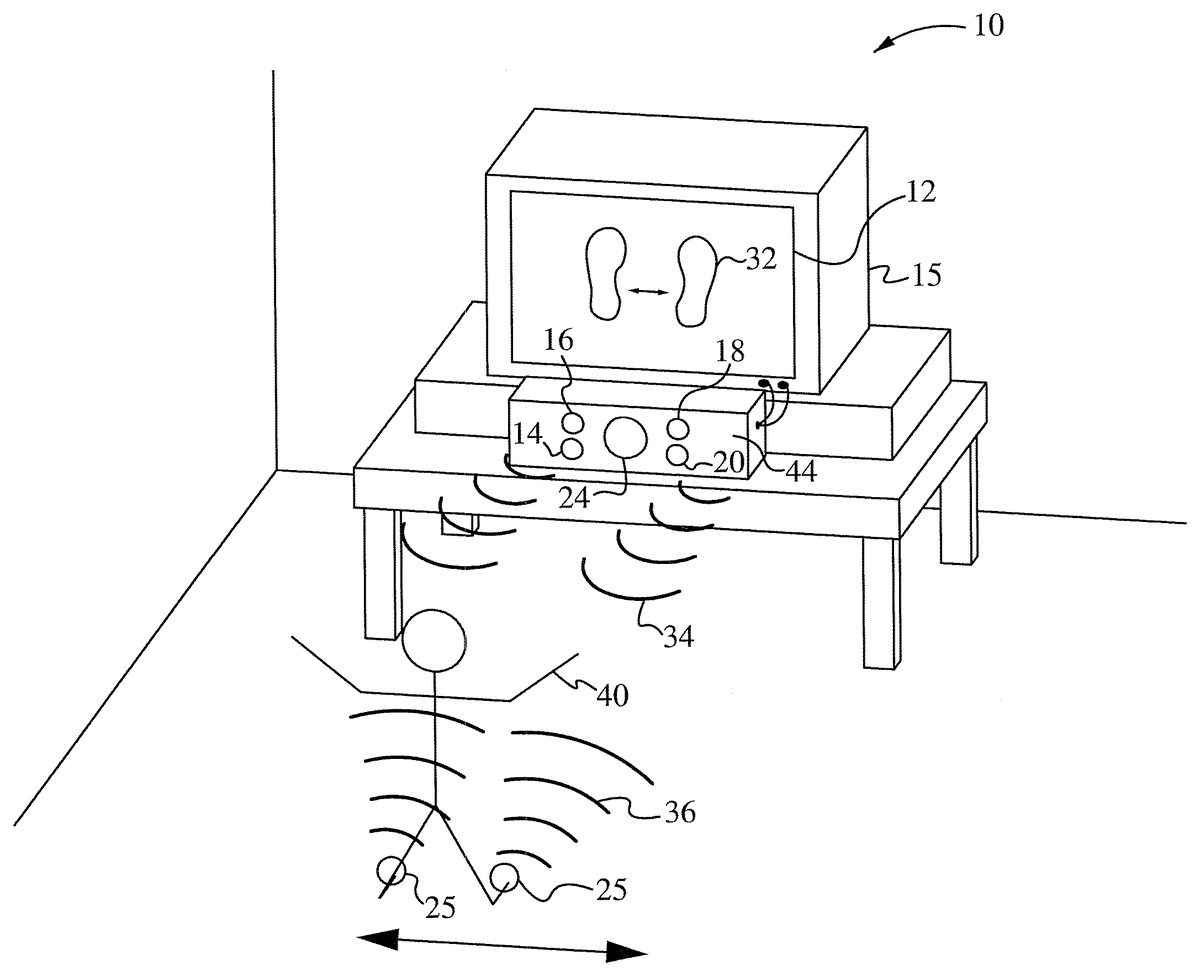
DETAILED DESCRIPTION In the following description, numerous details and alternatives are set forth for purpose of explanation. However, one of ordinary skill in the art will realize that the invention can be practiced without the use of these specific details. In other instances, well-known structures and devices are shown in block diagram form in order not to obscure the description of the invention with unnecessary detail. FIG. 1shows a first embodiment of the present invention. A video game device10having a display screen12of a display device15and a console44is shown. In the preferred embodiment, there are two light (e.g., optical) transmitters, though more can alternatively be used. In an exemplary, embodiment, a plurality of light transmitters14,16,18,20form a light transmitter array. A light receiver or detection array24is centrally located between the transmitters14,16,18,20. The optical transmitters14,16,18,20can be infrared transmitters, though other types of light transmitters (e.g., visible and non-visible), other optical transmitters, or other kinds of energy radiators can also be used. The detection array24can be a charge coupled device (CCD) and can include a lens. It will be apparent to those of ordinary skill in the art that other detectors can be used, in other configurations. Each transmitter14,16,18,20and the detection array24is coupled to a control circuit26via an intelligence module28(FIG. 2). The intelligence module28is coupled to the control circuit26to facilitate detection of a user motion or activity. The control circuit26is included in the console44to control a sensed user position as an image or a cursor on the screen12. Retroreflective “tags” or retroreflectors25are coupled to the feet or ankles of a player40or other part of the body. The retroreflectors25can include clips or buckles to mount to the user's shoes or can be on a Velcro® strap and mounted around the user's ankles. The retroreflectors25act as retroreflectors of light radiation that is transmitted by the transmitters14,16,18,20. ...
DETAILED DESCRIPTION
In the following description, numerous details and alternatives are set forth for purpose of explanation. However, one of ordinary skill in the art will realize that the invention can be practiced without the use of these specific details. In other instances, well-known structures and devices are shown in block diagram form in order not to obscure the description of the invention with unnecessary detail.
FIG. 1shows a first embodiment of the present invention. A video game device10having a display screen12of a display device15and a console44is shown. In the preferred embodiment, there are two light (e.g., optical) transmitters, though more can alternatively be used. In an exemplary, embodiment, a plurality of light transmitters14,16,18,20form a light transmitter array. A light receiver or detection array24is centrally located between the transmitters14,16,18,20. The optical transmitters14,16,18,20can be infrared transmitters, though other types of light transmitters (e.g., visible and non-visible), other optical transmitters, or other kinds of energy radiators can also be used. The detection array24can be a charge coupled device (CCD) and can include a lens. It will be apparent to those of ordinary skill in the art that other detectors can be used, in other configurations. Each transmitter14,16,18,20and the detection array24is coupled to a control circuit26via an intelligence module28(FIG. 2). The intelligence module28is coupled to the control circuit26to facilitate detection of a user motion or activity. The control circuit26is included in the console44to control a sensed user position as an image or a cursor on the screen12. Retroreflective “tags” or retroreflectors25are coupled to the feet or ankles of a player40or other part of the body. The retroreflectors25can include clips or buckles to mount to the user's shoes or can be on a Velcro® strap and mounted around the user's ankles. The retroreflectors25act as retroreflectors of light radiation that is transmitted by the transmitters14,16,18,20. In one embodiment, the video game device10can be plug and play. The plug and play video game device10does not require an extensive set up or programming by the user. The video game device10is operable by simply plugging into an audio and video jack of the display device15such as a television or audio and video jacks of a VCR, DVD player, or computer input.
InFIG. 1, the feet of the user40are shown to move first to the left and then in the right direction. If the video game device10is operating in a conventional display mode, the image of the user's feet will traverse a path on the screen12mimicking (illustrated at32) the path traversed by the movement of the user's feet. In an exemplary embodiment, the image appears as footprints32on the screen12.
FIG. 2shows a more detailed view of the transmitters14,16,18,20, the detection array24and the retroreflectors25. As in all the figures, identical labels refer to identical components. In an exemplary embodiment, the transmitters14,16,18,20are light emitting diodes (LEDs) and the detection array is an array of CCD receivers, such as used in some digital cameras, or an array of photo transistors. In addition,FIG. 2shows a representation of the transmitted light radiation34and the reflected radiation36. The radiation34is transmitted from the transmitters14,16,18,20. The radiation34is transmitted in all directions. For certain applications, the transmitted radiation can be columnized using lenses. Some portion of the transmitted radiation34will strike the retroreflectors25. That portion of the radiation34striking the retroreflectors25will be reflected, also in all directions. Using the array of transmitters14,16,18,20in combination with the detection array24allows determination of distance and movement of the retroreflectors25within three dimensional space. Such information facilitates the operation of certain video games.
The strength of reflected radiation must exceed background radiation levels.
Preferably, the detection array24is configured as a two dimensional array of receiver detectors, such as an array of CCD devices. In some embodiments, there can be receive optics positioned over the detection array24. The detection array24can be positioned to view an area of a surface, such as the floor. A user wearing retroreflectors25within the field of view on the floor will reflect radiation from the retroreflectors25to the detection array24. Certain elements in the detection array24will correspond to certain positions within the field of view on the floor. When a user's foot wearing a retroreflector25is in a location in the field of view, light radiation will be reflected and impinge on the corresponding elements in the detection array24. In this way, the detection array24can operate in a manner analogous to a digital camera. It will be appreciated that the detection array24can be configured to identify a user's foot when the sensed radiation exceeds a predetermined threshold for each of the elements in the detection array24.
The intelligence module28can detect a wide range of user motions or activities. The intelligence module28comprises a microprocessor configured to interact with the transmitters14,16,18,20and the detection array24. The intelligence module28interprets reflected radiation from the retroreflectors25and determines the user motion. The intelligence module28is configured to mimic an “intuitive” controller since multiple user activities can be determined. For example, the user can simulate a baseball swing and the intelligence module28determines the user motion to be a baseball swing. Alternatively, the user can simulate a golf swing and the intelligence module28determines the user motion to be a golf swing. The intelligence module28can be configured to distinguish the action of the user to be a baseball swing or a golf swing. The intelligence module28can determine patterns of reflected radiation received from the detection array24since certain elements in the detection array24correspond to certain positions within the three dimensional field of view of the detection array24. The intelligence module28can also determine the strength of reflected radiation and detect if the user motion is mostly a vertical motion as in a golf swing or a horizontal motion as in a baseball swing.
FIG. 3shows the receiver24in accordance with one embodiment of the invention, formed from an array of detectors200. In one embodiment, each of the detectors200is a charge coupled device, such that the array of detectors200functions as a camera. As shown inFIG. 3, each detector is labeled by an alpha-numeric character denoting its row and column. For example, the detector labeled “A3” is in the first row (“A”) and the third column. Similarly, the detector labeled “F8” detector is in the sixth row and eighth column.
FIGS. 4A and 4Bshow the array of detectors200receiving radiation reflected from a moving object. To makeFIGS. 4A and 4Beasier to read, only those labels necessary to explain the drawings are included. As shown by the relative shadings inFIG. 4A, the detector D5receives the most radiation (e.g., illumination) reflected from the object. The detectors C4-C6, D4, D6, and E4-6receive less radiation, and the remaining detectors receive none at all. At a later time, shown byFIG. 4B, with the object still being irradiated, the detector C5receives the most radiation reflected from the object. The detectors B5-B7, C5, C7, and D5-D7receive less radiation, and the remaining detectors receive none at all. This relative “movement” of radiation indicates that the object has moved in a direction corresponding to movement from D5to C6. Referring toFIG. 6Abelow, this movement is “reproduced” by moving the feet images32from location32A to32B.
While the array of detectors200is an 8×8 square, detectors of other sizes and configurations can also be used. Some examples includes larger square arrays, such as 256×256 array; smaller square arrays, such as 4×4; rectangular arrays; other uniform arrays, as well as non-uniform arrays. Those skilled in the art will recognize that different size and different configuration arrays can be selected to fit the application at hand.
FIG. 5shows the steps300of tracking and reproducing motion in a game device in accordance with one embodiment of the invention. In the step305, a game device is initialized to characterize motions. For example, if the game device is used to track and display moving feet, the user motions are “characterized by” and translated to moving feet. The game device is now ready for playing.
Referring to the device10ofFIG. 1to explain the steps300: In the step310radiation is transmitted from the transmitters14,16,18,20, reflected off the retroreflectors25, and, in the step315, received at the receiver24. In this example, the retroreflectors are attached to feet. When the steps310and315are performed sequentially, the motion of the feet are determined in the step320. In the step325, an image corresponding to the moving feet are displayed on the screen12.
In the step330, the method determines whether the game is finished. If the game is finished, the method proceeds to the step335, where the game ends. Otherwise, the method loops back to the step315.
Referring toFIGS. 2 and 5, in one embodiment each of the steps300is performed in either the control circuit26or the intelligence module28. In one embodiment, the control circuit26and the intelligence module28include a computer-readable medium containing computer readable instructions executed by a processor to perform the steps300.
The steps300are only exemplary. Some steps can be added, some steps can be deleted, and the steps can be performed in different orders than the one shown.
The retroreflectors25located within the volume of space sensed by embodiments of the present invention will be represented on the display screen12at a particular location. As the retroreflectors25moved and are positioned in a new location the relative analogue change in position will be displayed on the screen12. More precise position identification can be obtained through the use of precision components, such as optical lenses and circuitry.
In an exemplary embodiment of the present invention, it is desirable for the video game device10to sense the location of more than one object. Each of the players feet can be sensed separately. InFIGS. 6A-6C, the player40is positioned in order to see the display12. The display12is controlled in the usual manner as describe above by the video game device10which in some circumstances may be a personal computer. The display12can show, among other things, a caricature of the player as a dancer in a venue.
The video game device10separately identifies a left foot movement and a right foot movement. It can sense forward, backward and sideways movement. When utilizing embodiments of the present invention, the location of each foot of the player40can be uniquely determined by having a retroreflector25attached to each foot of the player40.
When utilizing embodiments of the present invention with this game, the control circuitry26can be set to register movement of the retroreflectors25after a particular threshold of reflected signal is received. This signifies that the player's feet are at least as close as some predefined limit to the detection array24. In the event that the player's feet are farther from the detection array24than allowable to achieve the appropriate threshold, no foot movement is indicated on the game screen12. When the player's feet and the retroreflectors25approach the detection array24sufficiently close that the threshold is crossed, the display screen12will then indicate movement of the player's left or right foot.
The transmitters14,16,18,20and the detection array24can be used to sense the reflected signal from the retroreflectors25and avoid the problem of having a left foot being misinterpreted as a right foot. Accordingly, the video game device10can distinguish the player's left foot from her right foot using kinematic rules whereby assumptions are made. These include assuming that at least one foot is always on the ground in static states and dynamic states with the exception of jumps.
FIGS. 7A and 7Bshow an alternative embodiment of the video game device10. The video game device10includes the light transmitters14,16,18,20, the detection array24and a first pair of retroreflectors25aon the user's feet and a second pair of retroreflectors25bon the user's hands. Each of the first and second pair of retroreflectors25a,25bcan include a filter element27a,27brespectively. In an exemplary embodiment, the transmitters14,16,18,20are infrared light emitting diodes (LEDs) and the detection array is an array of CCD receivers, such as used in some digital cameras, or an array of photo transistors. In addition,FIGS. 7A and 7Bshow a representation of the transmitted radiation34and the reflected radiation36aand36b. The radiation34is transmitted from the transmitters14,16,18,20. The radiation is transmitted in all directions. Some portion of the transmitted radiation34will strike the first pair of retroreflectors25aand the second pair of retroreflectors25b. That portion of the radiation striking the first and second pair of retroreflectors25a,25bwill be reflected, also in all directions. Using the array of transmitters14,16,18,20in combination with the detection array24allows determination of distance and movement of the first and second pair of retroreflectors25within three dimensional space.
The detection array24can be positioned to view an area, such as the three dimensional space in front of the video display device12. A user40wearing the first and second pair of retroreflectors25a,25bwithin the field of view in the area will reflect light radiation from the retroreflectors25a,25bto the detection array24. Certain elements in the detection array24will correspond to certain positions within the field of view in the area. When a user's feet wearing the retroreflectors25aor the user's hands wearing the retroreflectors25bare in a location in the field of view, radiation will be reflected and impinge on the corresponding elements in the detection array24. In this way, the detection array24can operate in a manner analogous to a digital camera. It will be appreciated that the detection array24can be configured to identify a user's feet or hands when the sensed reflected radiation exceeds a predetermined threshold for each of the elements in the detection array24.
The intelligence module28interprets reflected radiation from the first and second pairs of retroreflectors25a,25band determines the user motion. The intelligence module28is configured to mimic an intuitive controller since multiple user activities can be determined. For example, the user can simulate a baseball swing and the intelligence module28determines the user motion to be a baseball swing. The intelligence module28can determine patterns of reflected radiation received from the detection array24since certain elements in the detection array correspond to certain positions within the three dimensional field of view of the detection array24. The intelligence module28and the control circuit26are configured to detect and determine if reflected radiation36ais from the first pair of retroreflectors25aor reflected radiation36bis from the second pair of retroreflectors25b. Identifying the source of reflected radiation36a,36bcan be facilitated with the filter elements27a,27b. The filter elements27a,27bcan be active or passive devices that modify the transmitted radiation34. Alternatively, the intelligence module28and the control circuit26can similarly be configured to distinguish the movement of the user's right hand from the left hand or the right foot from the left foot.
FIGS. 8A and 8Bshow an alternative embodiment of the video game device10. The video game device10includes the light transmitters14,16,18,20, the detection array24and retroreflectors25. An audio device30such as a speaker is also included. In an alternative embodiment, each of the retroreflectors25can include a filter element as in the previous embodiment. In an exemplary embodiment, the transmitters14,16,18,20are light emitting diodes (LEDs) and the detection array is an array of CCD receivers such as in some digital cameras or an array of photo transistors. In addition,FIGS. 8A and 8Bshow a representation of the transmitted radiation34and the reflected radiation36. The radiation34is transmitted from the light transmitters14,16,18,20. The radiation is transmitted in all directions. Some portion of the transmitted radiation34will strike the retroreflectors25. That portion of the radiation striking the retroreflectors25will be reflected, also in all directions. Using the array of transmitters14,16,18,20in combination with the detection array24allows determination of distance and movement of the first and second pair retroreflectors25within three dimensional space.
The detection array24can be positioned to receive radiation within an area, such as the three dimensional space in front of a display device configured as a pretend mirror11. A user wearing the retroreflectors25within the field in the area will reflect radiation from the retroreflectors25to the detection array24. Certain elements in the detection array24will correspond to certain positions within the field of view in the area. When a user's hands wearing the retroreflectors25are in a location in the field of view, light radiation will be reflected and impinge on the corresponding elements in the detection array24. In this way, the detection array24can operate in a manner analogous to a digital camera. It will be appreciated that the detection array24can be configured to identify a user's hands when the sensed radiation exceeds a predetermined threshold for each of the elements in the detection array24.
The intelligence module28interprets reflected radiation from the retroreflectors25and determines the user motion. The intelligence module28is configured to mimic an intuitive controller since multiple user activities can be determined. The intelligence module28can determine patterns of reflected radiation received from the detection array24since certain elements in the detection array correspond to certain positions within the three dimensional field of view of the detection array24. The intelligence module28and the control circuit26can be configured to distinguish the movement of the user's right hand from left hand. For example, the user's hand motion can be determined as a grooming activity such as combing of the hair or brushing the teeth. In this way, the video gaming device can facilitate learning proper grooming habits as a grooming game.
FIGS. 9A and 9Bshow an alternative embodiment of the video game device100for playing a grooming game. The video game device100includes light transmitters114,118,122and the light receivers116,120,124. An audio device130such as a speaker is also included. The light transmitter and receiver pairs114,116,118,120and122,124form transceivers115,119and123respectively.FIGS. 9A and 9Bshow a representation of the transmitted light radiation34and the reflected radiation36. The light radiation34is transmitted from the transmitters114,120,122. The radiation is transmitted in all directions. Some portion of the transmitted radiation34will strike the user's body, for example the user's hand and a brush132. That portion of the radiation striking the brush132will be reflected, also in all directions. Using the array of light transmitters114,118,122in combination with the light receivers116,120,124allows determination of distance and movement of the user's body and the brush132within three dimensional space. It will be appreciated that the brush132can be identified when the sensed light radiation exceeds a predetermined threshold for each of the light receivers116,118,124.
The intelligence module128interprets reflected radiation from the user motion. The intelligence module128can determine patterns of reflected radiation received from the transceivers115,119,123within the three dimensional field of view. The intelligence module128and the control circuit126can be configured to distinguish the movement of the user's right hand from left hand. In an alternative embodiment, the brush132can include a filter element as in previous embodiments. In still another embodiment, the user can wear retroreflectors as in previous embodiments.
In an alternative embodiment, a cooking game with multiple venues can be substituted for the grooming game of the previous embodiment. In another embodiment, driving a car or flying a plane can be simulated using a device in accordance with the present invention. In still another embodiment, electronic devices such as personal computers or DVDs can be controlled by determining a user's movement as certain commands.
FIGS. 10A-10Dshow alternative embodiments of the video game device10ofFIG. 2. As shown inFIG. 10A, the device10includes light transmitters14,16,18,20, the detection array24and the game piece or bat42. A representation is shown of the transmitted light radiation34and the reflected radiation36. The radiation34is transmitted from the transmitters14,16,18,20. The radiation34is transmitted in all directions. For certain applications, the transmitted radiation34can be columnized using lenses. Some portion of the transmitted radiation34will strike the bat42. That portion of the radiation striking the bat42will be reflected, also in all directions. Using the array of transmitters14,16,18,20in combination with the detection array24allows determination of distance and movement of the bat42within three dimensional space.
In some embodiments, there can be receive optics positioned over the detection array24. The detection array24can be positioned to view an area in front of the detection array24. A user holding the bat42within the field of view will reflect light radiation from the bat42to the detection array24. Certain elements in the detection array24will correspond to certain positions within the field of view. When the bat42is in a location in the field of view, radiation will be reflected and impinge on the corresponding elements in the detection array24. In this way, the detection array24can operate in a manner analogous to a digital camera. It will be appreciated that the detection array24can be configured to identify the bat42when the sensed radiation exceeds a predetermined threshold for each of the elements in the detection array24.
The intelligence module28in the console44interprets reflected radiation from the bat42and determines the user motion. The intelligence module28is configured to mimic an “intuitive” controller since multiple user activities can be determined. The intelligence module28can determine the strength of reflected radiation and detect if the user motion is mostly a vertical motion as in a golf swing or a horizontal motion as in a baseball swing. The intelligence module28interprets and determines a swing arc “A” to be a baseball swing and registers a response on the display12by manipulating the cursor or presentation32.
FIG. 10Bshows the device10including light transmitters14,16,18,20, the detection array24and the game piece or golf club44. A representation is shown of the transmitted radiation34and the reflected radiation36. The light radiation34is transmitted from the transmitters14,16,18,20. The radiation is transmitted in all directions. Some portion of the transmitted radiation34will strike the golf club44. That portion of the radiation striking the golf club44will be reflected, also in all directions. Using the array of transmitters14,16,18,20in combination with the detection array24allows determination of distance and movement of the golf club44within three dimensional space.
In some embodiments, there can be receive optics positioned over the detection array24. The detection array24can be positioned to view an area in front of the detection array24. A user holding the golf club44within the field of view will reflect light radiation from the golf club44to the detection array24. Certain elements in the detection array24will correspond to certain positions within the field of view. When the golf club44is in a location in the field of view, radiation will be reflected and impinge on the corresponding elements in the detection array24. In this way, the detection array24can operate in a manner analogous to a digital camera. It will be appreciated that the detection array24can be configured to identify the golf club44when the sensed radiation exceeds a predetermined threshold for each of the elements in the detection array24.
The intelligence module28in the console44interprets reflected radiation from the golf club44and determines the user motion. The intelligence module28is configured to mimic an “intuitive” controller since multiple user activities can be determined. The intelligence module28can determine the strength of reflected radiation and detect if the user motion is mostly a vertical motion as in a golf swing or a horizontal motion as in a baseball swing. The intelligence module28interprets and determines a swing arc “B” to be a golf swing and registers a response on the display12by manipulating the cursor or presentation32.
FIG. 10C, shows an alternative embodiment including a game piece or tennis racket46. Again, radiation is transmitted from the transmitters14,16,18,20, reflected off the tennis racket46, and received at the detection array24. The intelligence module28in the console44determines the user motion along a swing arc ‘C’ to be a tennis swing and registers a response on the display12by manipulating the cursor or presentation32.FIG. 10D, shows an alternative embodiment including a gun game piece47. Again, radiation is transmitted from the transmitters14,16,18,20, reflected off the gun game piece47, and received at the detection array24. The intelligence module28in the console44determines the user motion “tracking” the hunting target32. In one embodiment, the user jerks the gun47to signify a shot. The detection array24and intelligence module28together recognize this motion as a shot. Based on the aim determined from the detection array24, the intelligence module28determines whether the target32was struck. In another embodiment, the gun game piece47generates an audible noise when its trigger is pulled to signify a shot. In still another embodiment, the gun game piece47includes other means recognized by the intelligence module to indicate a shot. The gun game piece47can itself reflect radiation or it can include a retroreflector that reflects radiation. Alternatively, a retroreflector can be attached directly to a user's hand to reflect radiation in accordance with embodiments of the invention.
FIGS. 11A-11Csimilarly show additional embodiments of the video game device10ofFIG. 2.FIG. 11A, shows an alternative embodiment including a game piece or boxing gloves48. Some embodiments can include retroreflectors25. The intelligence module28in the console44determines the user motion to be a punch or jab and registers a response on the display12by manipulating the cursor or presentation32. For example, in a kick boxing game either a hand motion or a foot motion could register as a blow to the opponent.FIG. 11B, shows an alternative embodiment including a game piece or bowling ball50. The intelligence module28in the console44determines the user motion along the swing arc “D” to be a throw of the bowling ball50and registers a response on the display12by manipulating the cursor or presentation32. For example, in a bowling game a motion of the bowling ball50could register as a strike or other combination.FIG. 11C, shows an alternative embodiment including a game piece or fishing rod52. The intelligence module28determines the user motion to be a cast of the fishing line and registers a response on the display12by manipulating the cursor or presentation32. In the embodiments ofFIGS. 11A-C, radiation is transmitted from the transmitters14,16,18,20, reflected off the boxing gloves and retroreflectors25(FIG. 11A), bowling ball50(FIG. 11B), a fishing rod52(FIG. 11C), respectively, and received at the receiver24, and processed as described in the other embodiments above.
FIG. 12Ashows one embodiment of a method of playing a video game. Referring toFIGS. 1 and 12A, the player40simply plugs the console44into her TV, attaches the retroreflectors25to her feet and literally steps into the game, using her body as the game controller. As the player40moves her feet, their movements will be mirrored by their ‘virtual footprints’ on the screen12. To play, the player40can follow actual footprint icons as they appear on the screen12to the beat of the music. The pace and difficulty level of the dance moves can gradually increase and the player40will be scored on her accuracy. The player40can track her accuracy by observing an accuracy meter58on the screen12. The video game device10can include energetic, fast-paced graphics and multiple levels of game play for each song. As the player40improves her skills, she can unlock additional levels of game play and new dance venues. In one embodiment, the player40can enjoy a game alone. Alternatively, the player40can challenge an additional player to face off arcade-style (FIG. 12B). To face off arcade style, the player40passes the retroreflectors25to the additional player. Alternatively, both players40can wear retroreflectors and dance within the field of view of the detection array24. The video game device10will keep track of each player's score.
FIG. 12Cshows an alternate embodiment of a method of playing a video game. The player40is challenged to follow along in an additional dance venue. The player40plugs the console44into a TV, attaches the wireless retroreflectors25to her feet and literally steps into the game. The player40uses her body as the game controller. As the player moves her feet, their movements will be mirrored by the virtual footprints on the screen12. To play, the player40can follow actual footprint icons as they appear on the screen12to recall an assortment of unique dance moves. The pace and difficulty level of the footprint icons can gradually increase and the player40will be scored on her accuracy. The player40can track her accuracy by observing an accuracy meter58on the screen12. The video game device10can include energetic, fast-paced graphics and multiple levels of game play for each venue. As the player40improves her skills, she can unlock additional levels of game play and new lounge venues.
FIG. 12Dshows an alternative embodiment of a method of playing a video game, in which the player40is challenged to escape from a notorious lounge filled with lizard-type characters. The player40plugs the console44into a TV, attaches the wireless retroreflectors25to her feet and literally steps into the game. The player40uses her body as the game controller. As the player moves her feet, their movements will be mirrored by their virtual footprints on the screen12. To play, the player40can follow actual footprint icons as they appear on the screen12to the beat of the music and to escape the lizard-type characters. The pace and difficulty level of the footprint icons will gradually increase and the player40will be scored on her accuracy. The video game device10can include energetic, fast-paced graphics and three levels of game play for each venue. As the player40improves her skills, she can unlock additional levels of game play and new lounge venues. In one embodiment, the player40can enjoy a game alone. Alternatively, the player40can challenge an additional player to face off arcade-style. The video game device10will keep track of each player's score.
FIG. 12Eshows an alternative embodiment of a method of playing a video game, in which the player40is challenged to spell interesting words. The player40plugs the console into a TV, attaches the wireless retroreflectors25to her feet and literally steps into the game. The player40uses her body as the game controller. As the player moves her feet, her movements will be mirrored by the virtual footprints on the screen12. To play, the player40can follow actual footprint icons as they appear on the screen to the beat of the music and to choose the proper letters as they appear on the screen12. In one embodiment, the letters can scroll across the display12until the player40chooses the letter with proper placement of the retroreflectors25. Alternatively, the letters can appear to fly into the scene and continue flying until being selected by the player40with proper movement of the retroreflectors25. The pace and difficulty level of the footprint icons will gradually increase and the player40will be scored on her accuracy. The video game device10can include energetic, fast-paced graphics and three levels of game play for each venue. As the player40improves her skills, she can unlock additional levels of game play and new venues for spelling. In one embodiment, the player40can enjoy a game alone. Alternatively, the player40can challenge an additional player to face off arcade-style. The video game device10will keep track of each player's score.
FIG. 12Fshows an alternative embodiment of a method of playing a video game, in which the player40is challenged to name interesting objects. The player40plugs the console into a TV, attaches the wireless retroreflectors25to her feet and literally steps into the game. The player40uses her body as the game controller. As the player moves her feet, their movements will be mirrored by their virtual footprints on the screen12. To play, the player40can follow actual footprint icons as they appear on the screen12to the beat of the music and to choose the proper objects as they appear on the screen12. In one embodiment, the object can scroll across the display12until the player40chooses the object with proper placement of the retroreflectors25. Alternatively, the objects can appear to fly into the scene and continue flying until being selected by the player40with proper movement of the retroreflectors25. The pace and difficulty level of the footprint icons will gradually increase and the player40will be scored on her accuracy. The video game device10can include energetic, fast-paced graphics and three levels of game play for each venue. As the player40improves her skills, she can unlock additional levels of game play and new venues for spelling. In one embodiment, the player40can enjoy a game alone. Alternatively, the player40can challenge an additional player to face off arcade-style. The video game device10will keep track of each player's score.
Still other embodiments exploit the fact that when flesh is close to an optical receiver (e.g., within one foot or less), the reflective nature of flesh approximates that of a retroreflector. In these embodiments, flesh, such as an exposed hand or foot, can substitute for a retroreflector. This permits a user's hands to be images for gaming and control applications. As one example, players use a computer to compete against one another in the game Rock, Scissors, Paper. The gestures for rock, scissors, and paper are all visually different enough for a computer to robustly recognize their shapes and process them in real time.
FIG. 13Ashows an electronic device400for recognizing gestures in accordance with the invention to play an electronic version of “Rock, Paper, Scissors.” In this embodiment, the hand is close enough to the receivers (here labeled “camera”) to function as a retroreflector.FIG. 13Bshows a result of a CIS test for a hand making a “Rock” gesture.FIG. 13Balso shows, adjacent to the result, corresponding readings of cycle and level.FIG. 13Cshows a result of a CIS test for a hand making a “Paper” gesture.FIG. 13Calso shows, adjacent to the result, corresponding readings of cycle and level.FIG. 13Dshows a result of a CIS test for a hand making a “Scissor” gesture.FIG. 13Dalso shows, adjacent to the result, corresponding readings of cycle and level. Together,FIGS. 13B-Dillustrate how the Rock, Paper, Scissors gestures can be distinguished from one another.
While the examples illustrate using embodiments of the invention in various games and activities, it will be appreciated that embodiments can also be used in other games, including, but not limited to, sword games, ping pong, billiards, archery, rifle shooting, aviation (e.g., flight simulation), and race car driving, to name only a few. Further, while some embodiments describe transmitting and receiving light energy for tracking objects, other types of radiant energy can be used. Further, while the examples discussed are generally directed to video games, it will be appreciated that the invention finds use in other applications other than games. One other embodiment, for example, includes a self-contained electronic device that tracks motion as described above and provides audio feedback.
While the invention has been described with reference to numerous specific details, one of ordinary skill in the art will recognize that the invention can be embodied in other specific forms without departing from the spirit of the invention. Thus, one of ordinary skill in the art will understand that the invention is not to be limited by the foregoing illustrative details, but rather is to be defined by the appended claims.
Claims
- An apparatus for tracking motion comprising: a transmitter configured to irradiate one or more objects;a receiver comprising an array of detectors arranged to receive reflected radiation from the one or more objects;a controller programmed to use the reflected radiation to track a motion of the one or more objects;and one or more retroreflectors, designed for attachment to the one or more objects, wherein the array of detectors comprises an array of charge coupled devices and wherein the receiver comprises one or more lenses arranged to focus the reflected radiation onto the array of charge coupled devices, such that the controller tracks the motion of the one or more objects by tracing the movement of a first area receiving a first level of reflected radiation and a second area receiving a second level of reflected radiation, wherein the first level of the reflected radiation is higher than the second level of reflected radiation, and the controller distinguishes among the one or more retroreflectors using kinematic rules.
- The apparatus of claim 1 , further comprising a monitor configured to display an image substantially reproducing the motion of the one or more objects.
- The apparatus of claim 1 , wherein each of the one or more retroreflectors comprises a filter element configured to modify transmitted radiation from the transmitter.
- The apparatus of claim 1 , wherein the transmitter comprises multiple light emitting diodes arranged to substantially uniformly illuminate an area containing the one or more objects.
- The apparatus of claim 1 , wherein the array of charge coupled devices is rectangular.
- The apparatus of claim 1 , wherein the one or more objects comprise feet, and the controller is further programmed to separately track motion of both feet.
- The apparatus of claim 1 , wherein the controller is further programmed to compare the motion to a predetermined target motion.
- The apparatus of claim 1 , wherein the one or more objects comprise a hairbrush.
- The apparatus of claim 3 , wherein the filter element is a passive device.
- The apparatus of claim 3 , wherein the filter element is an active device.
- A method of tracking motion comprising: irradiating one or more objects each supporting a corresponding retroreflector, wherein each retroreflector includes a filter element;receiving radiation reflected from the one or more retroreflectors onto an array of detectors;tracking motion of the one or more objects by tracing the movement of a first area receiving a first level of reflected radiation and a second area receiving a second level of reflected radiation, wherein the first level of the reflected radiation is higher than the second level of reflected radiation;and analyzing the motion to determine patterns of game play.
- The method of claim 11 , further comprising displaying an image on a monitor substantially reproducing the motion.
- The method of claim 12 , wherein the image comprises a picture of the one or more objects.
- The method of claim 11 , wherein the array of detectors comprises an array of charge coupled devices.
- The method of claim 14 , further comprising focusing the reflected radiation onto the array of charge coupled devices.
- The method of claim 11 , wherein the one or more objects comprise feet.
- The method of claim 11 , wherein the one or more objects comprise a sporting apparatus.
- The method of claim 17 , wherein the sporting apparatus is a bat, a club, a racket, a glove, a ball, a bow, a gun, or a fishing reel.
- The method of claim 11 , wherein the motion is used to select a character displayed to a user.
- A system comprising: at least one external object each having a diffusively reflective surface;and a self-contained electronic device configured to detect the at least one external object and to learn from current and past characteristics of each external object to thereby control at least one application element, wherein the self-contained electronic device comprises a controller configured to track a motion of the one or more objects by tracing the movement of a first area receiving a first level of reflected radiation and a second area receiving a second level of reflected radiation, wherein the first level of the reflected radiation is higher than the second level of reflected radiation.
- The system of claim 20 , wherein the self-contained electronic device includes a camera.
- The system of claim 20 , wherein the diffusively reflective surface comprises one of skin and clothing.
- An apparatus for tracking motion comprising: a transmitter configured to irradiate one or more objects;a receiver comprising an array of detectors arranged to receive reflected radiation from the one or more objects;a controller programmed to use the reflected radiation to track a motion of the one or more objects;and one or more retroreflectors, each designed for attachment to the one or more objects, wherein the array of detectors comprises an array of charge coupled devices and wherein the receiver comprises one or more lenses arranged to focus the reflected radiation onto the array of charge coupled devices, such that the controller tracks the motion of the one or more objects by tracing the movement of a first area receiving a first level of reflected radiation and a second area receiving a second level of reflected radiation, wherein the first level of the reflected radiation is higher than the second level of reflected radiation, and the controller distinguishes the type of motion.
Disclaimer: Data collected from the USPTO and may be malformed, incomplete, and/or otherwise inaccurate.