U.S. Pat. No. 9,375,638
GAME CONSOLE SWITCH BOX
Issue DateJanuary 2, 2014
Illustrative Figure
Abstract
An apparatus for dividing a split screen video game display into two separate video displays, for displaying two different screens. The apparatus includes a main switch box which connects to the game console and emulates all the connections expected by the game console. The main switch box wirelessly connects to a receiver switch box. The main switch box takes the video signal from the game console, divides the split screen into two halves, and outputs one half on a first screen connected to the main switch box and sends the other half to the receiver switch box for output on a second screen connected to the receiver switch box. The main switch box also takes a first headset input signal and a second headset input signal from the receiver switch box and combines the headset signals into one signal for sending to the game console.
Description
DETAILED DESCRIPTION OF THE PREFERRED EMBODIMENTS The implementations of the various features of the present invention are described with reference to the drawings. The drawings and the associated description are provided to illustrate preferred embodiments of the present invention and are not intended to limit the scope of the present invention. Throughout the drawings, like reference numbers are re-used to indicate correspondence between the referenced elements. In one preferred embodiment, a multiple room configuration100, shown inFIG. 1, includes a first room101and a second room102. The first room101includes a first display103, a game console105, a main switch box110, a first controller141, and a first headset142. The second room102includes a second display104, a receiver switch box120, a second controller143, and a second headset144. AlthoughFIG. 1shows various connections as wired, the connections may also be wireless. The first display103may be a television or other similar display device. The second display104may be a television or other similar display device, and may be the same size as, or a different size from the first display103. The game console105includes a computer, or other computing device capable of receiving user inputs. The game console105includes a first controller input port106, a second controller input port107, a headset input port108, and a multimedia output port109. The first controller input port106and the second controller input port107are data ports, such as USB ports, which allow videogame controllers such as the first controller141or other human interface devices, to connect to the game console105for user input. The headset input port108is a data or audio port, such as a USB port or a headphone jack, which allow headsets such as the headset142to connect to the game console105for audio. The multimedia output port109is a data or audio/video port, such as an HDMI port, which allows a display, such as the display103, to connect to the ...
DETAILED DESCRIPTION OF THE PREFERRED EMBODIMENTS
The implementations of the various features of the present invention are described with reference to the drawings. The drawings and the associated description are provided to illustrate preferred embodiments of the present invention and are not intended to limit the scope of the present invention. Throughout the drawings, like reference numbers are re-used to indicate correspondence between the referenced elements.
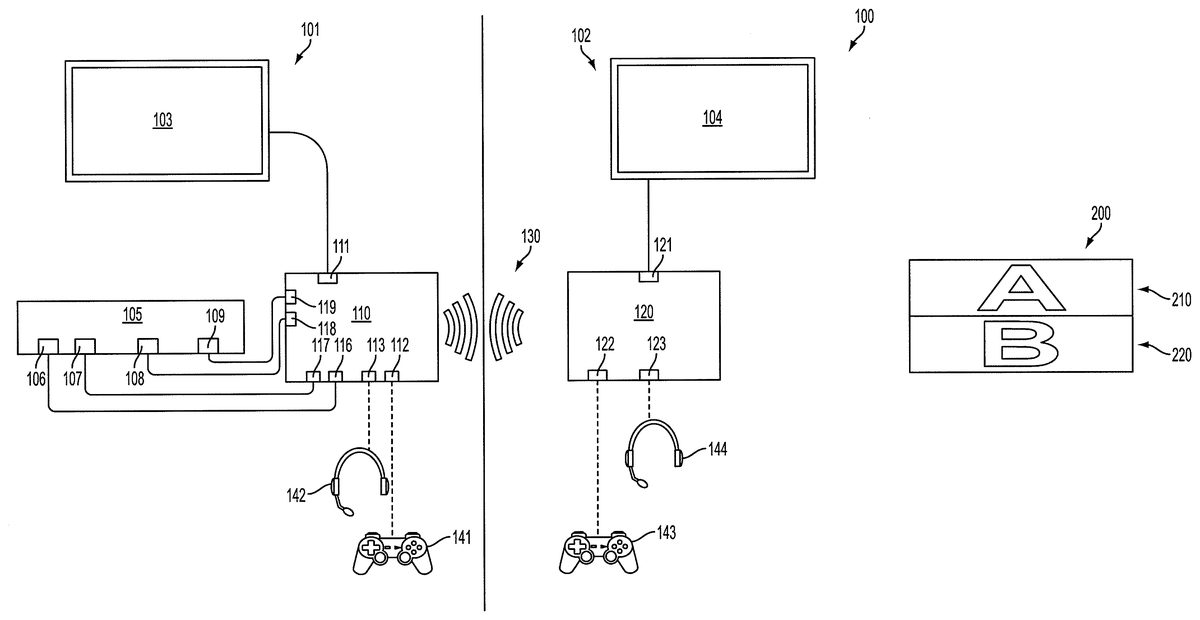
In one preferred embodiment, a multiple room configuration100, shown inFIG. 1, includes a first room101and a second room102. The first room101includes a first display103, a game console105, a main switch box110, a first controller141, and a first headset142. The second room102includes a second display104, a receiver switch box120, a second controller143, and a second headset144. AlthoughFIG. 1shows various connections as wired, the connections may also be wireless.
The first display103may be a television or other similar display device. The second display104may be a television or other similar display device, and may be the same size as, or a different size from the first display103.
The game console105includes a computer, or other computing device capable of receiving user inputs. The game console105includes a first controller input port106, a second controller input port107, a headset input port108, and a multimedia output port109. The first controller input port106and the second controller input port107are data ports, such as USB ports, which allow videogame controllers such as the first controller141or other human interface devices, to connect to the game console105for user input. The headset input port108is a data or audio port, such as a USB port or a headphone jack, which allow headsets such as the headset142to connect to the game console105for audio. The multimedia output port109is a data or audio/video port, such as an HDMI port, which allows a display, such as the display103, to connect to the game console for audio/video display. The multimedia output port109may include separate audio and video connections.
The main switch box110includes a first controller output port116, a second controller output port117, a headset output port118, a multimedia input port119, a multimedia output port111, a first controller input port112, and a headset input port113. The first controller output port116of the main switch box110connects to the first controller input port106of the game console105. The second controller output port117of the main switch box110connects to the second controller input port107of the game console105. The headset output port118of the main switch box110connects to the headset input port108of the game console105. The multimedia input port119of the main switch box110connects to the multimedia output port109of the game console105. The first controller141connects, either wirelessly or by wire, to the main switch box input port112. The headset142connects, either wirelessly or by wire, to the headset input port113of the main switch box110. The display103connects to the multimedia output port111of the main switch box110. These connections between the main switch box110and the game console105allow the game console105to behave as if the appropriate connections were made directly to it. For example, the game console105“sees” the first controller141as if it were directly connected to the game console105, even if there are intermediary connections. The game console105outputs audio and video to the display103through the main switch box110as if the game console105was directly connected to the display103.
A receiver switch box120has a second controller input port122, a second headset input port123, and a second multimedia output port121. A second controller143connects, either wirelessly or by wire, to the second controller input port122. A second headset144connects, either wirelessly or by wire, to the second headset input port123. A second display104connects to the second multimedia output port121of the receiver switch box120.
The receiver switch box120connects to the main switch box110preferably through a wireless link130. Although, the connection may be a wire line. The wireless connection130may be implemented as a direct wireless connection, or as part of a wireless network. The wireless connection130allows the second controller143to connect to the second controller input port107of the game console105.
The first headset142and the second headset144both connect to the headset input port108of the game console as if it was a direct connection to the game console105.
Because the game console105, and games playable on the game console105, may be configured for one headset, the main switch box110and the receiver switch box120allow two headsets to act as one. In other words, the same audio signal is output to the first headset142and the second headset144. The audio input from the first headset142is mixed with the audio input from the second headset144by the main switch box110before being sent to the game console105as a compound audio signal. The game console105receives the compound audio signal and behaves as if only one headset were connected. This allows two headsets to be used for a game console that only provides one headset input port108.
The receiver switch box120may output the same audio/video signal to the second display104as the main switch box110outputs to the first display103. The present invention allows two different video outputs to be displayed, one on each of first display103and second display104.FIG. 2Ashows how a two-player game is displayed on a single screen. The screen200shows a first player sub-screen210and a second player sub-screen220, in a split-screen configuration. AlthoughFIG. 2Ashows a horizontal split-screen, the screen may be split vertically or portioned in any other appropriate manner. As seen inFIG. 2A, the sharing of the screen200may cause the first player sub-screen210and the second player sub-screen220to be distorted, or otherwise modified, to fit the reduced screen space.
The main switch box110splits the video signal pushing the split-screen display into two separate video signals. This restores full screen display to the first player sub-screen210and the second player sub-screen220as shown inFIG. 2B. A first full screen display201displays only the first player sub-screen210. A second full screen display202displays only the second player sub-screen220. The first full screen display201may be the first display103ofFIG. 1. The second full screen display202may be the second display104ofFIG. 1. This allows each player to have his own display. As shown inFIG. 2B, each player sub-screen is stretched, to counteract distortion and use of the full screen. However, the output signal may remain unaltered in size. The main switch box110can determine from the video output signal from the game console105how to divide the images, and may pre-process a stretched image to be sent to the second player screen202from the receiver switch box120. Or, the actual second player sub-screen220may be sent to the receiver switch box120which appropriately scales the video signal for display on the second player screen101. Because of a delay in the wireless connection130between the switch box110and the receiver switch box120, there may be a 1 frame delay in the video.
FIG. 3illustrates a remote control300, which can be used to control video output settings. A menu button310prompts a menu on either the first display103and/or the second display104. The remote control300is preferably used with the main switch box110. Alternatively, the remote control300may be used with the receiver switch box120. The menu would then be displayed on the second display104. An exit button320exits the menu. Selection buttons330include an up button331, right button332, down button333, left button334, and OK button335, for making menu selections. Preset buttons340include a first button341, a second button342, and a third button343. The menu allows selection of which half or portion of the video display to send to which switch box, including scaling options. The same video may also be displayed on both switch boxes. Further options include which switch box is treated as which player, and headset mixing options, such as whether to mix or isolate headset signals. The preset buttons340are defined to preset settings.
Alternatively, the up button331selects the top half to be displayed on the main switch box110, and the down button333selects the bottom half to be displayed on the main switch box110. The OK button335switches between views, and the menu button goes to a split-screen (i.e. normal) view.
In certain other implementations, the functions of the remote control300may be performed by the first controller141or the second controller143. For example, certain uncommon button combinations on the first controller141may allow switching between different views. The main switch box110and/or the receiver switch box120can be configured to recognize specific button combinations from the first controller141and/or the second controller143.
FIG. 4illustrates a system400, an alternate embodiment of the present invention. Although the various connections are depicted as wire connections, one or more of the depicted connections may be wireless. A first room401includes a first display403, a game console405, a main switch box410, a first controller441, a second controller442, and a first headset451. A second room402includes a second display404, a receiver switch box420, a third controller443, a fourth controller444, and a second headset452.
The game console405includes a first controller input port406, a second controller input port407, a multimedia output port409, and a headset input port454.
The main switch box410includes a first multimedia output port411, a second multimedia output port414, a multimedia input port419, a first controller output port416, a second controller output port417, a first controller input port412, a second controller input port413, a first controller connection port415, a second controller connection port418, a multimedia switch431, a first controller switch432, a second controller switch433, and a headset connection453with the receiver switch box420.
The receiver switch box420includes a first controller input port422, a second controller input port423, a first controller output port425, a second controller output port428, a multimedia input port424, and a multimedia output port421.
The system400functions in a similar manner toFIG. 1, with respect to headset mixing and the video splitting functions. Only the differences will be discussed, for simplicity. The multimedia switch431, the first controller switch432, and the second controller switch433are preferably physical switches. They may, however, be implemented in logic. The multimedia switch431controls whether the audio/video signals are output to the first multimedia output port411, the second multimedia output port414, or both ports. The first controller switch432controls whether the first controller441or the third controller443is connected to the first controller input port406of the gaming console. Similarly, the second controller switch433controls whether the second controller442or the fourth controller444is connected to the second controller input port407of the gaming console. This configuration allows the game to be played in just the first room401, just the second room402(remote from the game console405), or split between the two rooms.
Those of ordinary skill would appreciate that the various illustrative logical blocks, modules, and algorithm steps described in connection with the examples disclosed herein may be implemented as electronic hardware, computer software, or combinations of both. Furthermore, the present application can also be embodied on a machine readable medium causing a processor or computer to perform or execute certain functions.
To clearly illustrate this interchangeability of hardware and software, various illustrative components, blocks, modules, circuits, and steps have been described above generally in terms of their functionality. Whether such functionality is implemented as hardware or software depends upon the particular application and design constraints imposed on the overall system. Skilled artisans may implement the described functionality in varying ways for each particular application, but such implementation decisions should not be interpreted as causing a departure from the scope of the disclosed apparatus and methods.
The various illustrative logical blocks, units, modules, and circuits described in connection with the examples disclosed herein may be implemented or performed with a general purpose processor, a digital signal processor (DSP), an application specific integrated circuit (ASIC), a field programmable gate array (FPGA) or other programmable logic device, discrete gate or transistor logic, discrete hardware components, or any combination thereof designed to perform the functions described herein. A general purpose processor may be a microprocessor, but in the alternative, the processor may be any conventional processor, controller, microcontroller, or state machine. A processor may also be implemented as a combination of computing devices, e.g., a combination of a DSP and a microprocessor, a plurality of microprocessors, one or more microprocessors in conjunction with a DSP core, or any other such configuration.
The steps of a method or algorithm described in connection with the examples disclosed herein may be embodied directly in hardware, in a software module executed by a processor, or in a combination of the two. The steps of the method or algorithm may also be performed in an alternate order from those provided in the examples. A software module may reside in RAM memory, flash memory, ROM memory, EPROM memory, EEPROM memory, registers, hard disk, a removable disk, a CD-ROM, or any other form of storage medium known in the art. An exemplary storage medium is coupled to the processor such that the processor can read information from, and write information to, the storage medium. In the alternative, the storage medium may be integral to the processor. The processor and the storage medium may reside in an Application Specific Integrated Circuit (ASIC). The ASIC may reside in a wireless modem. In the alternative, the processor and the storage medium may reside as discrete components in the wireless modem.
The previous description of the disclosed examples is provided to enable any person of ordinary skill in the art to make or use the disclosed methods and apparatus. Various modifications to these examples will be readily apparent to those skilled in the art, and the principles defined herein may be applied to other examples without departing from the spirit or scope of the disclosed method and apparatus. The described implementations are to be considered in all respects only as illustrative and not restrictive and the scope of the application is, therefore, indicated by the appended claims rather than by the foregoing description. All changes which come within the meaning and range of equivalency of the claims are to be embraced within their scope.
Claims
- An apparatus for dividing a split screen gaming video signal into separate video signals comprising: a main switch box connected to a first display, the main switch box including: a first controller input for receiving first controller signals, a first headset input for receiving first headset signals, a multimedia input for receiving multimedia signals, a first multimedia output for sending first video signals to the first display, a headset output for sending headset audio signals, a first controller output for sending the first controller signals, and a second controller output for sending second controller signals;and a receiver switch box remote from the main switch box, connected to a second display, and connected to the main switch box through a link, including: a second controller input for receiving second controller signals, a second headset input for receiving second headset signals, and a second multimedia output for sending second video signals to the second display;the main switch box receives the second controller signals from the receiver switch box through the link, receives the second headset signal from the receiver switch box through the link, combines the first headset signal and the second headset signal into a headset input signal, and separates the multimedia signal into a first screen signal and a second screen signal, sending the second screen signal to the receiver switch box through the link, wherein the first screen signal is a scaled first portion of the multimedia signal and the second screen signal is a scaled second portion of the multimedia signal.
- The apparatus of claim 1 , wherein the first screen signal is a top half of the multimedia signal, and the second screen signal is a bottom half of the multimedia signal.
- The apparatus of claim 1 , wherein the first screen signal is a bottom half of the multimedia signal, and the second screen signal is a top half of the multimedia signal.
- The apparatus of claim 1 , wherein the main switch box scales the second screen signal before sending the second screen signal to the receiver switch box.
- The apparatus of claim 1 , further comprising a remote control configured to adjust the first screen signal or the second screen signal.
- The apparatus of claim 1 , wherein the multimedia signal includes a digital video signal.
- The apparatus of claim 1 , wherein the multimedia signal includes an audio signal.
- A system for dividing a gaming video signal, comprising: a first video display;a second video display, remote from the first display;a first controller configured to output first controller signals;a second controller configured to output second controller signals;a first headset configured to output first audio signals;a second headset configured to output second audio signals;a game console configured to receive first controller signals, second controller signals, and headset audio signals, and output multimedia video/audio signals;a main switch box connected to the game console and the first display, the main switch box including: a first controller input for receiving the first controller signals, a first headset input for receiving the first headset audio signals, a multimedia input for receiving the multimedia signals from the game console, a first multimedia output for sending first screen signals to the first display, a headset output for sending headset audio signals to the game console, a first controller output for sending first controller signals to the game console, a second controller output for sending second controller signals to the game console;and a receiver switch box connected to the second display, and connected to the main switch box through a link, the receiver switch box including: a second controller input for receiving second controller signals from the second controller, a second headset input for sending second headset signals, a second multimedia output for sending second screen signals to the second display, the main switch box configured to receive the second controller signals from the receiver switch box through a link, receive the second headset signals from the receiver switch box through the link, and combine the first headset signals and the second headset signals into headset input signals, the main switch box configured to divide the multimedia signals into first screen signals and second screen signals and send the second screen signals to the receiver switch box through the link, wherein the first screen signals are a scaled first portion of the multimedia signals, and the second screen signals are a scaled second portion of the multimedia signals.
- The system of claim 8 , wherein the first screen signals are a top half display of the multimedia signals, and the second screen signals are a bottom half display of the multimedia signals.
- The system of claim 8 , wherein the first screen signals are a bottom half display of the multimedia signals, and the second screen signals are a top half display of the multimedia signals.
- The system of claim 8 , wherein the main switch box scales the second screen signals before sending the second screen signals to the receiver switch box.
- The system of claim 8 , further comprising a remote control configured to adjust the first screen signals or the second screen signals.
- The system of claim 8 , wherein the multimedia signals include digital video signals.
- The system of claim 8 , wherein the multimedia signals include audio signals.
- A system for dividing gaming video signals, comprising: a first display;a second display remote from the first display;a first controller;a second controller;a third controller;a fourth controller;a first headset;a second headset;a game console connected for receiving signals from the first controller, the second controller, and a headset, and output a multimedia signal;a main switch box connected to the game console and the first display, the main switch box including: a first controller input configured for receiving the first controller signals from the first controller, a second controller input for receiving second controller signals from the second controller, a first headset input for receiving first headset signals from the first headset, a multimedia input for receiving multimedia signals from the game console, a first multimedia output for sending a first screen signal to the first display, a headset output for sending headset audio signals to the game console, a first controller output for sending first controller signals or third controller signals to the game console as first controller signals, and a second controller output for sending second controller signals or fourth controller signals to the game console as second controller signals;and a receiver switch box connected to the second display and to the main switch box through a wireless link, the receiver switch box including: a third controller input;a fourth controller input;a second headset input, and a second multimedia output for sending second screen signals to the second display;the main switch box receiving third controller signals and fourth controller signals from the receiver switch box through the wireless link, receiving second headset audio signals from the receiver switch box through the wireless link and combining the first headset signals and the second headset signals into headset input signals, the main switch box dividing the multimedia signals into first screen signals and second screen signals and sending the second screen signals to the receiver switch box through the wireless link, wherein the first screen signals are a scaled first portion of the multimedia signals, and the second screen signals are a scaled second portion of the multimedia signals.
- The system of claim 15 , wherein a remote control selects the first controller signal or the third controller signal as the first controller input signal and selects the second controller signal or the fourth controller signal as the second controller input signal.
Disclaimer: Data collected from the USPTO and may be malformed, incomplete, and/or otherwise inaccurate.