U.S. Pat. No. 9,352,224
GATHERING PATH DATA FROM A MASSIVELY MULTIPLAYER ON-LINE ROLE-PLAYING GAME
AssigneeEMPIRE TECHNOLOGY DEVELOPMENT LLC
Issue DateApril 2, 2012
Illustrative Figure
Abstract
Technologies are generally disclosed for gathering path data from a massively multiplayer on-line role-playing game to determine a path through a mapping plane that may be a real-world or virtual-world representation.
Description
DETAILED DESCRIPTION In the following detailed description, reference is made to the accompanying drawings, which form a part hereof. In the drawings, similar symbols typically identify similar components, unless context dictates otherwise. The illustrative examples or embodiments described in the detailed description, drawings, and claims are not meant to be limiting. Other examples or embodiments may be utilized, and other changes may be made, without departing from the spirit or scope of the subject matter presented here. It will be readily understood that aspects of this disclosure, as generally described herein, and illustrated in the Figures, can be arranged, substituted, combined, and designed in a wide variety of different configurations, all of which are explicitly contemplated and make part of this disclosure. This disclosure is drawn, inter alia, to methods, apparatus, systems and computer program products for gathering path data from a massively multiplayer on-line role-playing game to determine a path through a mapping plane that may be a real-world or virtual-world representation. As contemplated in the present disclosure, even with the use of cloud computing, clustering or classification computing of pattern recognition that includes machine learning may still be prohibitively costly to end-users. Further, machine learning or artificial intelligence by itself may not be powerful enough or realistically cost effective for an end-user to reach a level of humanity in regards to clustering or classification computing of pattern recognition. In some examples, humanity intelligent resources in a cloud computing environment may provide an alternative to clustering or classification computing of pattern recognition that includes primarily machine learning. Humanity intelligent resources may be game players participating or involved in a massively multiplayer on-line role-player game (MMORG). Large numbers of game players may use human intelligence to augment clustering or classification computing of pattern recognition that includes machine learning. In some ...
DETAILED DESCRIPTION
In the following detailed description, reference is made to the accompanying drawings, which form a part hereof. In the drawings, similar symbols typically identify similar components, unless context dictates otherwise. The illustrative examples or embodiments described in the detailed description, drawings, and claims are not meant to be limiting. Other examples or embodiments may be utilized, and other changes may be made, without departing from the spirit or scope of the subject matter presented here. It will be readily understood that aspects of this disclosure, as generally described herein, and illustrated in the Figures, can be arranged, substituted, combined, and designed in a wide variety of different configurations, all of which are explicitly contemplated and make part of this disclosure.
This disclosure is drawn, inter alia, to methods, apparatus, systems and computer program products for gathering path data from a massively multiplayer on-line role-playing game to determine a path through a mapping plane that may be a real-world or virtual-world representation.
As contemplated in the present disclosure, even with the use of cloud computing, clustering or classification computing of pattern recognition that includes machine learning may still be prohibitively costly to end-users. Further, machine learning or artificial intelligence by itself may not be powerful enough or realistically cost effective for an end-user to reach a level of humanity in regards to clustering or classification computing of pattern recognition. In some examples, humanity intelligent resources in a cloud computing environment may provide an alternative to clustering or classification computing of pattern recognition that includes primarily machine learning. Humanity intelligent resources may be game players participating or involved in a massively multiplayer on-line role-player game (MMORG). Large numbers of game players may use human intelligence to augment clustering or classification computing of pattern recognition that includes machine learning.
In some examples, methods are implemented for gathering path data from an MMORG. The methods may include mapping one or more virtual points on a mapping plane. Each of the one or more virtual points may assert a repulsive force upon an object moved from a first area of the mapping plane to a second area of the mapping plane. The mapping plane may then be incorporated in a scene for the MMORG. In some examples, the one or more mapped virtual points may be separately decorated to fit one or more aspects of the scene. Also, path data may be gathered responsive to individual players of the MMORG moving their respective object through the scene from the first area of the mapping plane to the second area of the mapping plane. A minimum repulsive force path through the mapping plane may then be determined based, at least in part, on the gathered path data.
FIG. 1illustrates an example system100for gathering path data, arranged in accordance with at least some embodiments of the present disclosure. As shown inFIG. 1, system100includes an MMORG operator110, a path operator120, players130-1to130-n, and a network170. In some examples, as shown inFIG. 1, communication channels140-1to140-n, and communication channels150,160may communicatively couple players130-1to103-n, MMORG operator110and path operator120, respectively, to network170. Network170may be a communication medium such as the Internet to interconnect players130-1to103-n, MMORG operator110and path operator120. Also, in some examples, as shown inFIG. 1, MMORG operator110and path operator120may separately include a path manager180. As described in more detail below, path manager180may include logic and/or features configured to gather path data from an MMORG and determine a path through a mapping plane that may be a real-world or virtual-world representation (e.g., a building layout or a geographical layout).
Also, as shown inFIG. 1, MMORG operator110includes server(s)112. In some examples, server(s)112may be computing resources configured to host an MMORG involving a multitude of players130-1to130-n(where “n” represents an integer>3). For these examples, players130-1to130-nmay connect to or go on-line through network170(e.g., the Internet) to participate in the MMORG. As described in more detail below, path manager180at MMORG operator110may include logic and/or features configured to gather path data from the MMORG. The path data may be gathered responsive to individual players130-1to130-nseparately moving an object (e.g., a role-player) through one or more scenes in the MMORG. The object may be moved through a mapping plane incorporated in the one or more scenes. The mapping plane, for example, may include one or more virtual points, which assert repulsive forces to inhibit a player's efforts to move their object from one area of the mapping plane to another. Also, logic and/or features of path manager180at MMORG operator110may be configured to determine a minimum repulsive force path through the mapping plane based, at least in part, on path data gathered from players130-1to130-nmoving their respective objects through the mapping plane.
In some examples, as shown inFIG. 1, path operator120includes server(s)122. For these examples, server(s)122may be computing resources configured to host one or more scenes for an MMORG that may be primarily hosted by servers(s)112at MMORG operator110. For example, players130-1to130-nmay be redirected from server(s)112through network170to one or more scenes hosted by server(s)122at path operator120. For these examples, path manager180at MMORG operator110may include logic and/or features configured to gather path data from the one or more scenes of the MMORG hosted by server(s)122. The path data may be gathered responsive to individual players130-1to130-nseparately moving an object (e.g., a role-player) through the one or more scenes in the MMORG hosted by server(s)122. The object may be moved through a mapping plane incorporated in the one or more scenes. The mapping plane, for example, may include one or more virtual points, which assert repulsive forces to inhibit a player's efforts to move their object from one area of the mapping plane to another. Also, logic and/or features of path manager180at path operator120may be configured to determine a minimum repulsive force path through the mapping plane based, at least in part, on path data gathered from players130-1to130-nmoving their respective objects through the mapping plane.
According to some examples, communication channels140-1to140-n, or communication channels150,160may operate in accordance with one or more wired or wireless standards that enable MMORG operator110, path operator120or players130-1to130-nto communicatively couple to and through network170. These wired or wireless standards may be described in one or one or more industry standards such as those associated with IEEE 802.1, IEEE 802.11, IEEE 802.16, GSM, GPRS, EDGE, W-CDMA, HSPA, CDMA-2000, EV-DO, LTE or TD-LTE. Although this disclosure is not limited to only the above-mentioned wired or wireless standards.
FIG. 2illustrates a block diagram of an example architecture for path manager180, arranged in accordance with at least some embodiments of the present disclosure. As described above for system100inFIG. 1, MMORG operator110and/or path operator120may include path manager180. In some examples, path manager180includes features and/or logic configured or arranged to gather path data from an MMORG and determine a path through a mapping plane that may be a real-world or virtual-world representation.
The example path manager180ofFIG. 2, includes path logic210, control logic220, a memory230, input/output (I/O) interfaces240and optionally one or more applications250. As illustrated inFIG. 2, path logic210may be coupled to control logic220, memory230and I/O interfaces240. Also illustrated inFIG. 2, optional applications250may be arranged in cooperation with control logic220. Path logic210may further include one or more of a map feature211, a scene feature213, a gather feature215, a threshold feature217, or a determine feature219, or any reasonable combination thereof.
In some examples, the elements portrayed inFIG. 2's block diagram are configured to support or enable path manager180as described in this disclosure. A given path manager180may include some, all or more elements than those depicted inFIG. 2. For example, path logic210and control logic220may separately or collectively represent a wide variety of logic device(s) to implement the features of path manager180. An example logic device may include one or more of a computer, a microprocessor, a microcontroller, a field programmable gate array (FPGA), an application specific integrated circuit (ASIC), a sequestered thread or a core of a multi-core/multi-threaded microprocessor or a combination thereof.
In some examples, as shown inFIG. 2, path logic210includes one or more of a map feature211, a scene feature213, a gather feature215, a threshold feature217, or a determine feature219. Path logic210may be configured to use one or more of these features to perform operations. As described in more detail below, example operations may include gathering path data from an MMORG to determine a path through a mapping plane.
In some examples, control logic220may be configured to control the overall operation of path manager180. As mentioned above, control logic220may represent any of a wide variety of logic device(s) configured to operate in conjunction with executable content or instructions to implement the control of path manager180. In some alternate examples, the features and functionality of control logic220may be implemented within path logic210.
According to some examples, memory230is arranged to store executable content or instructions. The executable content or instructions may be used by control logic220and/or path logic210to implement or activate features or elements of path manager180. As described more below, memory230may also be arranged to temporarily maintain information associated with mapping virtual points in a mapping plane, incorporating the mapped virtual points in a scene for an MMORG and gathering path data from the scene to determine a minimum repulsive force through the mapping plane.
Memory230may include a wide variety of memory media including, but not limited to, one or more of volatile memory, non-volatile memory, flash memory, programmable variables or states, random access memory (RAM), read-only memory (ROM), or other static or dynamic storage media.
In some examples, I/O interfaces240may provide an interface via an local wired and/or wireless communication medium or link between path manager180and elements resident on or located with MMORG operator110(e.g., server(s)112) or path operator120(e.g., server(s)122). I/O interfaces240may include interfaces that operate according to various communication protocols to communicate over the local wired or wireless communication medium or link (e.g., I2C, SMBus, SPI, PCI-Express, USB, IEEE 802.1, IEEE 802.11, IEEE 802.16, etc). I/O interfaces240may also provide an interface between path manager180and elements located remote to MMORG operator110or path operator120. For example, as mentioned above forFIG. 1, MMORG operator110having path manager180may communicatively couple to players130-1to130-nvia communication channel150through network170. Also, path operator120having path manager180may communicatively couple to players130-1to130-nvia communication channel160through network170. I/O interfaces240, for example, include an interface configured to operate according to various wired or wireless communication protocols to allow path manager180at either MMORG operator110or path operator120to communicate over communication channel150and160, respectively. These wired or wireless communication protocols may include, but are not limited to, IEEE 802.1, IEEE 802.11, IEEE 802.16, GSM, GPRS, EDGE, W-CDMA, HSPA, CDMA-2000, EV-DO, LTE, TD-LTE.
In some examples, path manager180includes one or more applications250to provide instructions to control logic220and/or path logic210. These instructions, for example, may include instructions for path manager180to implement or use one or more of map feature211, scene feature213, gather feature215, threshold feature217, or determine feature219.
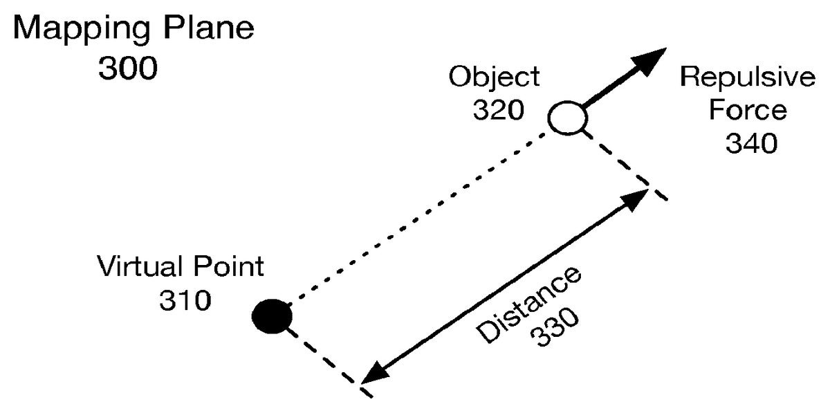
FIG. 3illustrates a diagram of an example mapping plane300, arranged in accordance with at least some embodiments of the present disclosure. As shown inFIG. 3, mapping plane300includes a virtual point310and an object320separated by a distance330. The virtual point310may be mapped from a sample of clustering or classification method. In some examples, as shown inFIG. 3, a repulsive force340may be asserted or applied on object320by virtual point310. The repulsive strength of repulsive force340, in some examples, may decrease as a distance value associated with distance330increases. Thus, for example, to minimize the effects of repulsive force340, object320may be moved from a first portion of mapping plane300to a second portion of mapping plane300such that a maximum distance is maintained.
In some examples, a mapping plane, such as mapping plane300, may be a real-world or virtual-world representation. A real-world representation may include, but is not limited to, a building layout, a community layout, a city layout, an assembly line layout, a topographical map, a battlefield map, a city street map, a regional freight route map, a national freight route map, an international freight route map, a communication network map, a cloud computing network, or any combinations thereof. A virtual-world representation may include, but is not limited to, a building layout, a forest layout, an ocean layout, a desert layout, a mountain layout, a battlefield map, a community/village layout, a city layout, a city street map, or any combinations thereof.
According to some examples where mapping plane300may be a real-world representation, object320may represent a physical entity. For example, object320may represent a person, a vehicle, a ship, an animal, an electrical signal, etc. For these examples, virtual point310may represent items in the real-world that may inhibit the movement of the physical entity as the physical entity is moved from a physical location associated with a first area of mapping plane300to another physical location associated with a second area of mapping plane300. For example, object320may represent a person and mapping plane300may be a community layout. Virtual point310may assert a repulsive force such as a barrier or obstacle that inhibits or slows down the person's movement from one part of the community to another part of the community.
FIG. 4illustrates a diagram of another example mapping plane400, arranged in accordance with at least some embodiments of the present disclosure. As shown inFIG. 4, mapping plane includes virtual points410A and410B and an object420. Object420is also shown as being a distance430A from a virtual point410A and a distance430B from a virtual point410B. In some examples, as shown inFIG. 4, repulsive forces440A and440B may be asserted or applied on object420by virtual points410A and410B, respectively. Also, a resultant repulsive force460, as shown inFIG. 4, shows the total or summation of repulsive forces440A and440B on object420. In some examples, resultant repulsive force460may change as object420or virtual points410A,410B move to different positions of mapping plane400.
In some examples, similar to what was mentioned above for repulsive force340forFIG. 3, the repulsive strengths of repulsive forces440A and440B, may decrease as distance values associated with distance430A and/or distance430B increase. Thus, for an example where virtual points410A and410B assert equal repulsive forces on object420, the effects of repulsive force applied by440A and/or repulsive force applied by440B may be minimized when object420is moved from a first portion of mapping plane400to a second portion of mapping plane400such that a maximum distance between both repulsive forces is maintained. That maximum distance may follow a path identified as minimum repulsive force path (MRFP)450inFIG. 4.
In some examples, virtual points410A and410B may be mapped to mapping plane400. The mapping of virtual points410A and410B may be based on either a 2-dimensional or 3-dimensional mapping plane. For an example of a 2-dimensional mapping plane, virtual points410A and410B may be included among a multitude of virtual points that may be mapped to mapping plane400. The multitude of virtual points may compose a point set P={p1, . . . , pj, . . . , pm}, where point pj, indicates an ordinary point on mapping plane400. Also, j is an integer and 1≦j≦m. So for a 2-dimensional mapping plane, let (xj, yj) denote the coordinates of pjin the 2-dimensional mapping plane. Example equation (1) may be used to calculate the value of xj, yj.
xj=α1*attbi1j; yj=α2*attbi2j, (1)
For example equation (1), α1, α2are weights and attb1j, attbi2jare attributes associated with the virtual point mapped at pj. In some examples, attbi1j, attbi2jmay be associated with certain attributes of the virtual point such as a type of structure or geographical feature (e.g., a tree, a building, a depression/hole, bushes rocks, water, grass, sand, etc.). For example, attbi1jmay be an attribute for a given virtual point in the x direction and attbi2jmay be another attribute for the given virtual point in the y direction of mapping plane400. For the virtual point set P, which number of attributes exceeds 2 or 3, dimensionality reduction algorithms will be used so as to fit the points to 2-dimensional or 3-dimensional plane. Also, α1may be a weight associated with a size of attbi1jfor the given virtual point in the x direction of mapping plane400and α2may be a weight associated with a size of attbi2jfor the given virtual point in the y direction of mapping plane400. For example, if the attribute was a body of water, a larger body of water may have a larger weight value associated with α1or α2in the x and y directions, respectively.
According to some examples, a value may be associated with an amount of repulsive force (e.g., repulsive force440A) that a virtual point (e.g., virtual point410A) located at pjmay assert on an object (e.g., object420) at a given location on mapping plane400. Example equation (2) depicts a way to show the value as related to how the repulsive force may change as the distance between the object and source of the repulsive force changes.
{right arrow over (fp1)}={right arrow over (Fc)}/d(2)
For example equation (2), {right arrow over (fpj)}represents the value associated with the amount of repulsive force asserted by a virtual point at pjand {right arrow over (Fc)} represents the unit repulsive force asserted by a virtual point. {right arrow over (Fc)} is a constant with a default value, it can be set by users. Also, for example equation (2), d represents the distance the object is from the virtual point at pj. Thus, when d equals to zero, {right arrow over (Fc)} will be ∞.
In some examples, repulsive forces asserted in total on an object for all virtual points mapped to a mapping plane may be determined for a given point/coordinate of a mapping plane. Example equation (3) may depict a way to show the resultant total repulsive force from a multitude of virtual points located at various points in mapping plane400.
Fres→=∑pj∈Pfpj→(3)
For example equation (3), {right arrow over (Fres)} represents the resultant force and equates to a summation of total repulsive force asserted by virtual points located at various points of point set P. In some examples, as shown inFIG. 4, MRFP450shows an anticipated path the player may move object420in order to minimize the amount of {right arrow over (Fres)}460. So, in some examples, if a player of an MMORG wants to rapidly move object420from one portion of mapping plane400to another portion of mapping plane, the player may move object420in such a way as to minimize the amount of repulsive force asserted by virtual points410A and410B.
FIG. 5illustrates an example diagram of minimum repulsive force paths through a mapping plane, arranged in accordance with at least some embodiments of the present disclosure. In some examples, point sets may be divided and clustered on a mapping plane500as shown inFIG. 5. The point sets are depicted inFIG. 5as point sets510A-C. Also, for these examples, MRFPs520A-C may indicate anticipated minimum repulsive force paths an object may be moved from one portion of mapping plane500to another portion of mapping plane500.
According to some examples, point set510A may represent a cluster of virtual points. For example, point set510A may represent a forest while point set510B may represent a grouping of buildings and point set510C may represent a swamp or concentration of water features. A player of an MMORG may move an object along any of the MRFPs520A-B to minimize repulsive forces asserted by the various virtual points depicted inFIG. 5.
FIG. 6illustrates an example scene that incorporates a mapping plane having virtual points decorated to fit the scene, arranged in accordance with at least some embodiments of the present disclosure. In some examples, as shown inFIG. 6, a forest610, a village620and a swamp630may be representations of point sets510A-C that have been decorated or dressed up to fit a scene of an MMORG. For these examples, players of the MMORG may see individual virtual points from point set510A as trees or antagonists (e.g., wild animals or hostile forces) that may be included in the forest. The players may also see various virtual points from point set510B as buildings, houses or antagonists in a village or hostile inhabitants of the village. Further, players of the MMORG may also see virtual points from point set510C as water features such as bogs, swamps or antagonists included in the swamp.
FIG. 7illustrates a flow chart of example methods for gathering path data, arranged in accordance with at least some embodiments of the present disclosure. In some examples, elements of system100, mapping plane500or scene600as shown inFIG. 1, 5 or 6may be used to illustrate example methods related to the flow chart depicted inFIG. 7. Path manager180as shown inFIG. 2may also be used to illustrate the example methods. But the described methods are not limited to implementations on system100, mapping plane500or scene600as shown inFIG. 1, 5 or 6or to path manager180shown inFIG. 2. The example methods may be implemented on other systems having one or more of the elements depicted inFIG. 1, 2, 5 or 6.
Moving from the start to block710(Map virtual points), path manager180located with either MMORG operator110or path operator120may include logic and/or features configured to map one or more virtual points (e.g., via map feature211) on mapping plane500. In some examples, each of the one or more virtual points may assert a repulsive force upon an object moved from a first area of mapping plane500to a second area of mapping plane500. For these examples, similar to what was mentioned above for mapping plane300, mapping plane500may be a real-world or virtual-world representation.
Continuing from block710to block720(Incorp. Mapping Plane in Scene), path manager180may include logic and/or features configured to incorporate mapping plane500in a scene (e.g., via scene feature213) for an MMORG. For example, mapping plane500may be incorporated in scene600by decorating point-sets510A-C to fit one or more aspects of the scene (e.g., forest, village, swamp, etc.).
In some examples, mapping plane500may be a virtual-world representation and a portion of mapping plane500may be decorated as a virtual-world forest in scene600. The virtual-world forest may include individual virtual points decorated to represent obstacles or repulsive forces that may slow down or block movement of an object from the first area of mapping plane500to the second area of mapping plane500. These obstacles may include trees, buildings, holes, depressions, bushes, rocks, water, grass, sand or antagonists (e.g., hostile forces). Also, another portion of mapping plane may be decorated to include a building (e.g., a castle) having one or more levels or floors. For this other portion, individual virtual points may be decorated to represent obstacles in the building that may slow down the movement of the object. These obstacles may include walls, floors, ceilings, stairs, furniture or antagonists.
Continuing from block720to block730(Gather Path Data), path manager180may include logic and/or features configured to gather path data (e.g., via gather feature215) in response to players130-1to130-nof the MMORG moving their respective object through scene600. In some examples, while scene600is visited by players130-1to130-n, each player's path through scene600is gathered and at least temporarily stored (e.g., in memory230).
Continuing from block730to decision block740(Path Data Threshold Reached?), path manager180may include logic and/or features configured to determine if a path data threshold has been reached (e.g., via threshold feature217). In some examples, the path data threshold may be predetermined amount of path data gathered from players130-1to130-nvisiting scene600that may be needed or desired to determine one or more minimum repulsive force path(s) (MRFP(s)) through mapping plane500decorated to fit scene600. If a determination is made that a path data threshold has been reached, the process moves to block750. Otherwise, the process moves back to block730to gather more path data.
According to some examples, each player's path through scene600may be saved into set Upathi. Where Upathi={(x1i, y1i), . . . (xni, yni)}, and i is the path order. Also, (x1i, y1i) are coordinates of a player's entrance position into scene600(assuming 2-dimensional mapping plane500) and (xni, yni) are coordinates of the player's exit position from scene600. For these examples, according to the coordinates, the position on mapping plane500that is passed by individual player objects may be determined. Thus, when a coordinate on mapping plane500is passed by a given player's object, a frequency count may be updated (e.g., incremented by a count of 1). For this example, the frequency count may be depicted as Freq(x1,y1)to show how a count may be maintained for each coordinate.
Moving from decision block740to block750(Determine MRFP(s)), path manager180may include logic and/or features configured to determine an MRFP through mapping plane500(e.g., via determine feature219). In some examples, the MRFP is determined based on the path data gathered above. For these examples, the MRFP may represent a path that players of the MMORG have collectively shown to be the fastest route to move an object through mapping plane500that has been decorated as scene600.
Continuing from block750to decision block760(Acceptable MRFP?), path manager180may include logic and/or features configured to determine whether an acceptable MRFP has been found (e.g., via determine feature219). In some examples, a determined MRFP may not be practical or realistically obtainable in a real-world scenario. For example, mapping plane500may be a representation of a city layout and the determined MRFP may have a path that runs through private property not available for sale. If the purpose of the mapping plane is to route a public road through the city, the determined MRFP may not be acceptable. If the MRFP is not acceptable, the process moves back to block710and the virtual points or obstacles that made the MRFP unacceptable may be added to mapping plane500. Otherwise, the process comes to an end.
In some examples, scene600may be hosted by server(s)112of MMORG operator110. For these examples, logic and/or features of a path manager180at MMORG operator may gather the path data and determine the MRFP for mapping plane500. Alternatively, scene600may be hosted by server(s)122of path operator120. For these alternatives, logic and/or features of a path manager180at path operator120may gather the path data and determine the MRFP for mapping plane500. In these alternative examples, path operator120may work with MMORG operator110to provide ways for players of an MMORG hosted by MMORG operator110to enter scene600. These ways may include incentives (e.g., coupons, experience points, virtual-world currency, virtual-world tools/weapons, etc.) for players to choose to enter scene600. Once a player has moved through scene600, they may then be routed back to the MMORG hosted by server(s)112of MMORG operator110.
FIG. 8illustrates a block diagram of an example computer program product800, arranged in accordance with at least some embodiments of the present disclosure. In some examples, as shown inFIG. 8, computer program product800includes a signal bearing medium802that may also include instructions804for gathering path data from a massively multiplayer on-line role-playing game. Instructions804, which, when executed by logic (e.g., path logic210), may cause the logic to map one or more virtual points on a mapping plane. Each of the one or more virtual points may assert a repulsive force upon an object moved from a first area of the mapping plane to a second area of the mapping plane. The instructions804may also cause the logic to incorporate the mapping plane in a scene for the massively multiplayer on-line role-playing game. In some examples, the one or more mapped virtual points are separately decorated to fit one or more aspects of the scene. The instructions804may also cause the logic to gather path data responsive to individual players of the massively multiplayer on-line role-playing game moving their respective object through the scene from the first area of the mapping plane to the second area of the mapping plane and determine a minimum repulsive force path through the mapping plane based, at least in part, on the gathered path data.
Also depicted inFIG. 8, in some examples, computer program product800may include one or more of a computer readable medium806, a recordable medium808and a communications medium810. The dotted boxes around these elements depict different types of mediums included within, but not limited to, signal bearing medium802. These types of mediums may distribute instructions804to be executed by logic (e.g., path logic210). Computer readable medium806and recordable medium808may include, but are not limited to, a flexible disk, a hard disk drive (HDD), a Compact Disc (CD), a Digital Versatile Disk (DVD), a digital tape, a computer memory, etc. Communications medium810may include, but is not limited to, a digital and/or an analog communication medium (e.g., a fiber optic cable, a waveguide, a wired communication link, a wireless communication link, etc.).
FIG. 9illustrates an example computing device900, arranged in accordance with at least some embodiments of the present disclosure. In some examples, path manager180depicted inFIG. 1 or 2may be implemented on computing device900. In these examples, elements of computing device900may be arranged or configured to gather path data from an MMORG and determine a path through a mapping plane that may be a real-world or virtual-world representation. In a very basic configuration901, computing device900typically includes one or more processors910and system memory920. A memory bus930can be used for communicating between the processor910and the system memory920.
Depending on the desired configuration, processor910can be of any type including but not limited to a microprocessor (μP), a microcontroller (μC), a digital signal processor (DSP), or any combination thereof. Processor910can include one more levels of caching, such as a level one cache911and a level two cache912, a processor core913, and registers914. The processor core913can include an arithmetic logic unit (ALU), a floating point unit (FPU), a digital signal processing core (DSP Core), or any combination thereof. A memory controller915can also be used with the processor910, or in some implementations the memory controller915can be an internal part of the processor910.
Depending on the desired configuration, the system memory920can be of any type including but not limited to volatile memory (such as RAM), non-volatile memory (such as ROM, flash memory, etc.) or any combination thereof. System memory920typically includes an operating system921, one or more applications922, and program data924. Application922includes instructions923that are arranged to perform the functions as described herein including the actions described with respect to path manager180architecture shown inFIG. 2or including the actions described with respect to the flow charts shown inFIG. 7. Program Data924includes path data925that is useful for implementing instructions923(e.g., determining a path data threshold or a minimum repulsive force path). In some examples, application922can be arranged to operate with program data924on an operating system921such that implementations for instructions for gathering path data from an MMORG and determining a path through a mapping plane may be provided as described herein. This described basic configuration is illustrated inFIG. 9by those components within dashed line901.
Computing device900can have additional features or functionality, and additional interfaces to facilitate communications between the basic configuration901and any required devices and interfaces. For example, a bus/interface controller940can be used to facilitate communications between the basic configuration901and one or more data storage devices950via a storage interface bus941. The data storage devices950can be removable storage devices951, non-removable storage devices952, or a combination thereof. Examples of removable storage and non-removable storage devices include magnetic disk devices such as flexible disk drives and hard-disk drives (HDD), optical disk drives such as compact disk (CD) drives or digital versatile disk (DVD) drives, solid state drives (SSD), and tape drives to name a few. Example computer storage media can include volatile and nonvolatile, removable and non-removable media implemented in any method or technology for storage of information, such as computer readable instructions, data structures, program modules, or other data.
System memory920, removable storage951and non-removable storage952are all examples of computer storage media. Computer storage media includes, but is not limited to, RAM, ROM, EEPROM, flash memory or other memory technology, CD-ROM, digital versatile disks (DVD) or other optical storage, magnetic cassettes, magnetic tape, magnetic disk storage or other magnetic storage devices, or any other medium which can be used to store the desired information and which can be accessed by computing device900(e.g., baseband representations of signals). Any such computer storage media can be part of computing device900.
Computing device900can also include an interface bus942for facilitating communication from various interface devices (e.g., output interfaces, peripheral interfaces, and communication interfaces) to the basic configuration901via the bus/interface controller940. Example output interfaces960include a graphics processing unit961and an audio processing unit962, which can be configured to communicate to various external devices such as a display or speakers via one or more A/V ports963. Example peripheral interfaces970include a serial interface controller971or a parallel interface controller972, which can be configured to communicate with external devices such as input devices (e.g., keyboard, mouse, pen, voice input device, touch input device, etc.) or other peripheral devices (e.g., printer, scanner, etc.) via one or more I/O ports973. An example communication interface980includes a network controller981, which can be arranged to facilitate communications with one or more other computing devices990over a network communication via one or more communication ports982. A network communication connection is one example of a communication media. Communication media may typically be embodied by computer readable instructions, data structures, program modules, or other data in a modulated data signal, such as a carrier wave or other transport mechanism, and includes any information delivery media. A “modulated data signal” can be a signal that has one or more of its characteristics set or changed in such a manner as to encode information in the signal. By way of example, and not limitation, communication media can include wired media such as a wired network or direct-wired connection, and wireless media such as acoustic, radio frequency (RF), infrared (IR) and other wireless media. The term computer readable media as used herein can include both storage media and communication media.
Computing device900can be implemented as a portion of a personal computer including both laptop computer and non-laptop computer configurations or implemented in a workstation or a server configuration.
References made in this disclosure to the term “responsive to” or “in response to” are not limited to responsiveness to a particular feature and/or structure. A feature may also be responsive to another feature and/or structure and also be located within that feature and/or structure. Moreover, when terms or phrases such as “coupled” or “responsive” or “in response to” or “in communication with”, etc. are used herein or in the claims that follow, these terms should be interpreted broadly. For example, the phrase “coupled to” may refer to being communicatively, electrically and/or operatively coupled as appropriate for the context in which the phrase is used.
Those skilled in the art will recognize that it is common within the art to describe devices and/or processes in the fashion set forth herein, and thereafter use engineering practices to integrate such described devices (e.g., transmitters, receivers, wireless devices, computing platforms, computing devices, etc.) and/or methods into data processing systems. That is, at least a portion of the devices and/or methods described herein can be integrated into a data processing system via a reasonable amount of experimentation. Those having skill in the art will recognize that a typical data processing system generally includes one or more of a system unit housing, a video display device, a memory such as volatile and non-volatile memory, processors such as microprocessors and digital signal processors, computational entities such as operating systems, drivers, graphical user interfaces, and applications programs, one or more interaction devices, such as a touch pad or screen, and/or control systems including feedback loops and control motors (e.g., feedback for sensing position and/or velocity; control motors for moving and/or adjusting components and/or quantities). A typical data processing system may be implemented utilizing any suitable commercially available component, such as those typically found in data computing/communication and/or network computing/communication systems.
The herein described subject matter sometimes illustrates different components or elements contained within, or connected with, different other components or elements. It is to be understood that such depicted architectures are merely examples, and that in fact many other architectures can be implemented which achieve the same functionality. In a conceptual sense, any arrangement of components to achieve the same functionality is effectively “associated” such that the desired functionality is achieved. Hence, any two components herein combined to achieve a particular functionality can be seen as “associated with” each other such that the desired functionality is achieved, irrespective of architectures or intermedial components. Likewise, any two components so associated can also be viewed as being “operably connected”, or “operably coupled”, to each other to achieve the desired functionality, and any two components capable of being so associated can also be viewed as being “operably couplable”, to each other to achieve the desired functionality. Specific examples of operably couplable include but are not limited to physically mateable and/or physically interacting components and/or wirelessly interactable and/or wirelessly interacting components and/or logically interacting and/or logically interactable components.
With respect to the use of substantially any plural and/or singular terms herein, those having skill in the art can translate from the plural to the singular and/or from the singular to the plural as is appropriate to the context and/or application. The various singular/plural permutations may be expressly set forth herein for sake of clarity.
It will be understood by those within the art that, in general, terms used herein, and especially in the appended claims (e.g., bodies of the appended claims) are generally intended as “open” terms (e.g., the term “including” should be interpreted as “including but not limited to,” the term “having” should be interpreted as “having at least,” the term “includes” should be interpreted as “includes but is not limited to,” etc.). It will be further understood by those within the art that if a specific number of an introduced claim recitation is intended, such an intent will be explicitly recited in the claim, and in the absence of such recitation no such intent is present. For example, as an aid to understanding, the following appended claims may contain usage of the introductory phrases “at least one” and “one or more” to introduce claim recitations. However, the use of such phrases should not be construed to imply that the introduction of a claim recitation by the indefinite articles “a” or “an” limits any particular claim containing such introduced claim recitation to inventions containing only one such recitation, even when the same claim includes the introductory phrases “one or more” or “at least one” and indefinite articles such as “a” or “an” (e.g., “a” and/or “an” should typically be interpreted to mean “at least one” or “one or more”); the same holds true for the use of definite articles used to introduce claim recitations. In addition, even if a specific number of an introduced claim recitation is explicitly recited, those skilled in the art will recognize that such recitation should typically be interpreted to mean at least the recited number (e.g., the bare recitation of “two recitations,” without other modifiers, typically means at least two recitations, or two or more recitations). Furthermore, in those instances where a convention analogous to “at least one of A, B, and C, etc.” is used, in general such a construction is intended in the sense one having skill in the art would understand the convention (e.g., “a system having at least one of A, B, and C” would include but not be limited to systems that have A alone, B alone, C alone, A and B together, A and C together, B and C together, and/or A, B, and C together, etc.). In those instances where a convention analogous to “at least one of A, B, or C, etc.” is used, in general such a construction is intended in the sense one having skill in the art would understand the convention (e.g., “a system having at least one of A, B, or C” would include but not be limited to systems that have A alone, B alone, C alone, A and B together, A and C together, B and C together, and/or A, B, and C together, etc.). It will be further understood by those within the art that virtually any disjunctive word and/or phrase presenting two or more alternative terms, whether in the description, claims, or drawings, should be understood to contemplate the possibilities of including one of the terms, either of the terms, or both terms. For example, the phrase “A or B” will be understood to include the possibilities of “A” or “B” or “A and B.”
While various aspects and embodiments have been disclosed herein, other aspects and embodiments will be apparent to those skilled in the art. The various aspects and embodiments disclosed herein are for purposes of illustration and are not intended to be limiting, with the true scope and spirit being indicated by the following claims.
Claims
- A processor-implemented method to determine a path through a scene in a massively multiplayer on-line role-playing game, the method comprising: mapping, by the processor, one or more virtual points on a mapping plane, each of the one or more virtual points representing an item in the scene which asserts a repulsive force upon an object moved from a first area of the mapping plane to a second area of the mapping plane;incorporating, by the processor, the mapping plane in the scene for the massively multiplayer on-line role-playing game, wherein the one or more mapped virtual points are separately decorated to fit one or more aspects of the scene;gathering, by the processor, path data responsive to individual players of the massively multiplayer on-line role-playing game moving their respective object through the scene from the first area of the mapping plane to the second area of the mapping plane;storing, in a non-transitory machine-readable memory, at least temporarily, path data for the individual players, the path data for their respective object comprising an array of coordinates which track their respective object's path from an entry point in the scene to an exit point in the scene;and determining whether a path data threshold has been reached, wherein the path data threshold represents a minimum amount of path data necessary to determine a minimum repulsive force path through a mapping plane, and in response to a determination that the path data threshold has been reached, determining a minimum repulsive force path through the mapping plane based, at least in part, on the gathered path data.
- The method of claim 1 , wherein determining the minimum repulsive force path comprises determining the minimum repulsive force path once a threshold amount of path data has been gathered.
- The method of claim 1 , wherein the repulsive force exerted on an object by an item varies as a function of a distance between the object and the item, an wherein determining the minimum repulsive force path through the mapping plane comprises determining a path which minimizes a sum of all repulsive forces acting on an object by a plurality of items in the mapping plane.
- The method of claim 1 , wherein the mapping plane is a real-world representation of one of a building layout, a community layout, a city layout, an assembly line layout, a topographical map, a battlefield map, a city street map, a regional freight route map, a national freight route map, an international freight route map, a communication network map or a cloud computing network.
- The method of claim 4 , wherein the mapped virtual points represent items in the real- world that inhibit the movement of the object as the object is moved from a physical location associated with the first area of the mapping plane to another physical location associated with the second area of the mapping plane.
- The method of claim 1 , wherein the mapping plane is a virtual-world representation of one of a building layout, a forest layout, an ocean layout, a desert layout, a mountain layout, a battlefield map, a community layout, a city layout or a city street map.
- The method of claim 6 , wherein the mapped virtual points represent items in the virtual-world that inhibit the movement of the object as the object is moved from a virtual-world location associated with the first area of the mapping plane to another virtual-world location associated with the second area of the mapping plane.
- The method of claim 1 , wherein the scene for the massively multiplayer on-line role- playing game comprises one or more levels of a virtual- world building and the virtual points are separately decorated to represent obstacles to move the object from the first area of the mapping plane to the second area of the mapping plane, the obstacles to include at least one of walls, floors, ceilings, stairs, furniture or antagonists.
- The method of claim 1 , wherein the scene for the massively multiplayer on-line role- playing game comprises a virtual-world forest and the virtual points are separately decorated to represent obstacles to move the object from the first area of the mapping plane to the second area of the mapping plane, the obstacles to include one of trees, buildings, holes, bushes, rocks, water, grass, sand or antagonists.
- The method of claim 1 , wherein the scene for the massively multiplayer on-line role- playing game is hosted by one or more servers that are operated by a different operator than an operator of the massively multiplayer on-line role-playing game.
- An apparatus configured to determine a path through a scene in a massively multiplayer on-line role- playing game, the apparatus comprising: a path manager logic to: map one or more virtual points on a mapping plane, each of the one or more virtual points representing an item in the scene which asserts a repulsive force upon an object moved from a first area of the mapping plane to a second area of the mapping plane;incorporate the mapping plane in the scene for the massively multiplayer on-line role-playing game, wherein the one or more mapped virtual points are separately decorated to fit one or more aspects of the scene;gather path data responsive to individual players of the massively multiplayer on-line role-playing game moving their respective object through the scene from the first area of the mapping plane to the second area of the mapping plane;store, in a non-transitory machine-readable memory, at least temporarily, path data for the individual players, the path data for their respective object comprising an array of coordinates which track their respective object's path from an entry point in the scene to an exit point in the scene;and determine whether a path data threshold has been reached, wherein the path data threshold represents a minimum amount of path data necessary to determine a minimum repulsive force path through a mapping plane, and in response to a determination that the path data threshold has been reached determine a minimum repulsive force path through the mapping plane based, at least in part, on the gathered path data.
- The apparatus of claim 11 , wherein the repulsive force exerted on an object by an item varies as a function of a distance between the object and the item, an wherein determining the minimum repulsive force path through the mapping plane comprises determining a path which minimizes a sum of all repulsive forces acting on an object by a plurality of items in the mapping plane.
- The apparatus of claim 11 , wherein the mapping plane is a real- world representation of one of a building layout, a community layout, a city layout, an assembly line layout, a topographical map, a battlefield map, a city street map, a regional freight route map, a national freight route map, an international freight route map, a communication network map or a cloud computing network.
- The apparatus of claim 13 , wherein the mapped virtual points represent items in the real-world that inhibit the movement of the object as the object is moved from a physical location associated with the first area of the mapping plane to another physical location associated with the second area of the mapping plane.
- The apparatus of claim 11 , wherein the logic configured to incorporate the mapping plane in the scene comprises the logic further configured to incorporate the mapping plane by prompting the individual players to at least temporarily leave the massively multiplayer on- line role-playing game in order to move their respective object through the scene, wherein the scene is hosted by one or more servers that are operated by a different operator than the operator of the massively multiplayer on-line role-playing game.
- A system configured to determine a path through a scene in a massively multiplayer on-line role-playing game, the system comprising: one or more servers to host the massively multiplayer on-line role-playing game;and a path manager having logic, the logic configured to: map one or more virtual points on a mapping plane, each of the one or more virtual points representing an item in the scene which asserts a repulsive force upon an object moved from a first area of the mapping plane to a second area of the mapping plane;incorporate the mapping plane in the scene for the massively multiplayer on-line role-playing game, wherein the one or more mapped virtual points are separately decorated to fit one or more aspects of the scene;gather path data responsive to individual players of the massively multiplayer on-line role-playing game moving their respective object through the scene from the first area of the mapping plane to the second area of the mapping plane;store, in a non-transitory machine-readable memory, at least temporarily, path data for the individual players, the path data for their respective object comprising an array of coordinates which track their respective object's path from an entry point in the scene to an exit point in the scene;and determine whether a path data threshold has been reached, wherein the path data threshold represents a minimum amount of path data necessary to determine a minimum repulsive force path through a mapping plane, and in response to a determination that the path data threshold has been reached, determine a minimum repulsive force path through the mapping plane based, at least in part, on the gathered path data.
- The system of claim 16 , wherein the logic configured to determine the minimum repulsive force path comprises the logic further configured to determine the minimum repulsive force path once a threshold amount of path data has been gathered.
- The system of claim 16 , wherein the mapping plane is a virtual- world representation of one of a building layout, a forest layout, an ocean layout, a desert layout, a mountain layout, a battlefield map, a community layout, a city layout or a city street map.
- The system of claim 18 , wherein the mapped virtual points represent items in the virtual-world that inhibit the movement of the object as the object is moved from a virtual- world location associated with the first area of the mapping plane to another virtual-world location associated with the second area of the mapping plane.
- A computer program product comprising a non-transitory medium having instructions for determining a path through a scene in a massively multiplayer on-line role-playing game, which, when executed by logic, cause the logic to: map one or more virtual points on a mapping plane, each of the one or more virtual points representing an item in the scene which asserts a repulsive force upon an object moved from a first area of the mapping plane to a second area of the mapping plane;incorporate the mapping plane in the scene for the massively multiplayer on-line role- playing game, wherein the one or more mapped virtual points are separately decorated to fit one or more aspects of the scene;gather path data responsive to individual players of the massively multiplayer on-line role-playing game moving their respective object through the scene from the first area of the mapping plane to the second area of the mapping plane;store, in a non-transitory machine-readable memory, at least temporarily, path data for the individual players, the path data for their respective object comprising an array of coordinates which track their respective object's path from an entry point in the scene to an exit point in the scene;and determine whether a path data threshold has been reached, wherein the path data threshold represents a minimum amount of path data necessary to determine a minimum repulsive force path through a mapping plane, and in response to a determination that a path data threshold has been reached, determine a minimum repulsive force path through the mapping plane based, at least in part, on the gathered path data.
- The computer program product of claim 20 , wherein the instructions to cause the logic to determine the minimum repulsive force path comprises the instructions to further cause the logic to determine the minimum repulsive force path once a threshold amount of path data has been gathered.
- The computer program product of claim 20 , wherein the repulsive force exerted on an object by an item varies as a function of a distance between the object and the item, and wherein determining the minimum repulsive force path through the mapping plane comprises determining a path which minimizes a sum of all repulsive forces acting on an object by a plurality of items in the mapping plane.
Disclaimer: Data collected from the USPTO and may be malformed, incomplete, and/or otherwise inaccurate.