U.S. Pat. No. 9,345,963
COMPUTER-READABLE STORAGE MEDIUM, GAME APPARATUS, GAME SYSTEM AND GAME PROCESSING METHOD
AssigneeNintendo Co Ltd
Issue DateJanuary 26, 2012
Illustrative Figure
Abstract
A setting change image is displayed on an LCD of a terminal device while an in-play user is playing a game while viewing a game image displayed on a monitor. A user different from the in-play user can change various settings of the game without hindering the progress of the game performed by the in-play user, by operating the terminal device while viewing the setting change image displayed on the LCD, such as increasing the number of participants in the game, and changing difficulty level of the game.
Description
DETAILED DESCRIPTION OF NON-LIMITING EXAMPLE EMBODIMENTS With reference toFIG. 1, a game system according to an exemplary embodiment will be described. As shown inFIG. 1, a game system1includes a household television receiver (hereinafter, referred to as a monitor)2which is an example of display means, and a stationary game apparatus3connected to the monitor2via a connection cord. The monitor2includes loudspeakers2a. The game apparatus3includes an optical disc4, a game apparatus body5, a terminal device6, and controllers7ato7d(hereinafter these may be simply referred to as a controller7when they need not to be distinguished from each other). The optical disc4has stored therein an information processing program (typically, a game program) to be executed by the game apparatus body5. The monitor2displays a game image outputted by the game apparatus body5. The monitor2includes the loudspeakers2a. The loudspeakers2aeach output a game sound outputted from the game apparatus body5. The game apparatus body5performs game processing and the like based on a game program or the like stored in the optical disc4. The controller7includes a plurality of operation sections (operation buttons). The controller7transmits to the game apparatus body5operation data (controller operation data) indicating an input state of the operation sections (whether each of the operation buttons has been pressed) using, for example, the technology of Bluetooth (registered trademark). The controller7is provided with an imaging section for taking an image of a marker8including two LED modules (hereinafter, referred to as “markers”)8L and8R provided in the vicinity of the display screen of the monitor2(above the screen inFIG. 1), and an imaging information calculation section for calculating the position of the marker in the taken image by the imaging section. The position of the marker calculated by the imaging information calculation section is transmitted to the game apparatus body5as marker coordinate data. The game apparatus body5can calculate the movement, position, attitude and the like ...
DETAILED DESCRIPTION OF NON-LIMITING EXAMPLE EMBODIMENTS
With reference toFIG. 1, a game system according to an exemplary embodiment will be described.
As shown inFIG. 1, a game system1includes a household television receiver (hereinafter, referred to as a monitor)2which is an example of display means, and a stationary game apparatus3connected to the monitor2via a connection cord. The monitor2includes loudspeakers2a. The game apparatus3includes an optical disc4, a game apparatus body5, a terminal device6, and controllers7ato7d(hereinafter these may be simply referred to as a controller7when they need not to be distinguished from each other).
The optical disc4has stored therein an information processing program (typically, a game program) to be executed by the game apparatus body5.
The monitor2displays a game image outputted by the game apparatus body5. The monitor2includes the loudspeakers2a. The loudspeakers2aeach output a game sound outputted from the game apparatus body5.
The game apparatus body5performs game processing and the like based on a game program or the like stored in the optical disc4.
The controller7includes a plurality of operation sections (operation buttons). The controller7transmits to the game apparatus body5operation data (controller operation data) indicating an input state of the operation sections (whether each of the operation buttons has been pressed) using, for example, the technology of Bluetooth (registered trademark).
The controller7is provided with an imaging section for taking an image of a marker8including two LED modules (hereinafter, referred to as “markers”)8L and8R provided in the vicinity of the display screen of the monitor2(above the screen inFIG. 1), and an imaging information calculation section for calculating the position of the marker in the taken image by the imaging section. The position of the marker calculated by the imaging information calculation section is transmitted to the game apparatus body5as marker coordinate data. The game apparatus body5can calculate the movement, position, attitude and the like of the controller7based on the marker coordinate data.
Moreover, the controller7is provided with an acceleration sensor and a gyro sensor. Acceleration data indicating the acceleration detected by the acceleration sensor and angular velocity data indicating the angular velocity detected by the gyro sensor are transmitted to the game apparatus body5. The game apparatus body5can calculate the orientation and movement of the controller7, based on the acceleration data and/or angular velocity data.
The terminal device6is a portable device that is small enough to be held by a user, and the user is allowed to move the terminal device6with hands, or place the terminal device6at any location. Although a specific structure of the terminal device6will be described later, the terminal device6includes an LCD (Liquid Crystal Display)61as display means, and input means (a touch panel62, a gyro sensor604, and the like described later). The terminal device6and the game apparatus body5are communicable with each other wirelessly or via a cable. The terminal device6receives, from the game apparatus body5, data of an image (e.g., a game image) generated in the game apparatus body5, and displays the image represented by the data on an LCD61. Although in the exemplary embodiment an LCD is used as a display device, the terminal device6may include any other display device, such as a display device utilizing EL (Electro Luminescence), for example. Further, the terminal device6transmits, to the game apparatus body5, operation data representing the content of an operation performed on the terminal device6.
Next, with reference toFIG. 2, an internal structure of the game apparatus body5will be described.FIG. 2is a block diagram illustrating an example of an internal structure of the game apparatus body5. The game apparatus body5includes a CPU (Central Processing Unit)10, a system LSI (Large Scale Integration)11, an external main memory12, a ROM/RTC (Read Only Memory/Real Time Clock)13, a disc drive14, an AV-IC (Audio Video-Integrated Circuit)15and the like.
In addition to the CPU10, the external main memory12, the ROM/RTC13, the disc drive14, and the AV-IC15are connected to the system LSI11. The external main memory12, which is a volatile memory, is used as a work area and a buffer area for the CPU10. The ROM/RTC13includes a ROM (so-called boot ROM) incorporating a program for booting the game apparatus body5, and a clock circuit (RTC) for counting time. The disc drive14reads, from the optical disc4, program data, texture data and the like, and writes the read data into an internal main memory35described below or the external main memory12.
The system LSI11includes an input/output processor (I/O processor)31, a GPU (Graphics Processor Unit)32, a DSP (Digital Signal Processor)33, a VRAM (Video RAM)34, and the internal main memory35.
The GPU32generates an image in accordance with a graphics command (draw command) supplied from the CPU10. In the exemplary embodiment, the game apparatus body5may generate both a game image to be displayed on the monitor2and a game image to be displayed on the terminal device6. Hereinafter, the game image to be displayed on the monitor2may be referred to as a “monitor game image”, and the game image to be displayed on the terminal device6may be referred to as a “terminal game image”.
The DSP33, serving as an audio processor, generates sound data by using sound data and sound waveform (tone quality) data stored in the internal main memory35and the external main memory12. In the exemplary embodiment, similarly to the game images, both a game sound to be outputted from the loudspeakers2aof the monitor2and a game sound to be outputted from the loudspeakers of the terminal device6may be generated. Hereinafter, the game sound to be outputted from the monitor2may be referred to as a “monitor game sound”, and the game sound to be outputted from the terminal device6may be referred to as a “terminal game sound”.
Among the image data and sound data generated by the game apparatus body5, the image data and sound data to be outputted to the monitor2are read by the AV-IC15. Through an AV connector16, the AV-IC15outputs the read image data to the monitor2and outputs the read sound data to the loudspeakers2aincluded in the monitor2. Thereby, an image is displayed on the monitor2, and a sound is outputted from the loudspeakers2a.
Further, among the image data and sound data generated by the game apparatus body5, the image data and sound data to be outputted to the terminal device6are transmitted to the terminal device6by the I/O processor31or the like. Data transmission to the terminal device6by the I/O processor31or the like will be described later.
The I/O processor31executes data reception and transmission with the components connected thereto, and download of data from an external apparatus. The I/O processor31is connected to the flash memory17, the network communication module18, the controller communication module19, an extension connector20, a memory card connector21, and a codec LSI27. The codec LSI27is connected to the terminal communication module28.
The game apparatus body5is connected to a network such as the Internet so as to communicate with external information processing apparatuses (for example, other game apparatuses or various servers). That is, the I/O processor31is connected to a network via the network communication module18and the antenna22so as to communicate with external information processing apparatuses connected to the network. The flash memory17may store not only the data transmitted and received between the game apparatus body5and the external information processing apparatuses, but also saved data (result data or progress data of the process) of the game played with the game apparatus body5. Further, the flash memory17may store programs such as a game program.
The game apparatus body5can receive operation data from the controller7. That is, the I/O processor31receives, via the antenna23and the controller communication module19, operation data or the like transmitted from the controller7, and stores (temporarily) the data in a buffer region of the internal main memory35or the external main memory12.
The game apparatus body5is capable of transmitting/receiving image data, sound data and the like to/from the terminal device6. The I/O processor31outputs data of a game image (terminal game image) generated by the GPU32to the codec LSI27. The codec LSI27performs a predetermined compression process on the image data supplied from the I/O processor31. The terminal communication module28performs wireless communication with the terminal device6. Accordingly, the image data compressed by the codec LSI27is transmitted by the terminal communication module28to the terminal device6via the antenna29. Therefore, in the exemplary embodiment, the codec LSI27compresses the image data by using a highly efficient compression technique, for example, the H.264 standard. The codec LSI27may adopt other compression techniques. When the communication rate is sufficiently high, uncompressed image data may be transmitted. The terminal communication module28is, for example, a Wi-Fi certified communication module. The terminal communication module28may perform wireless communication with the terminal device6at a high speed by using, for example, the technique of MIMO (Multiple Input Multiple Output) adopted in the IEEE802.11n standard, or may use other communication techniques.
The game apparatus body5transmits, to the terminal device6, sound data as well as the image data. That is, the I/O processor31outputs sound data (terminal game sound) generated by the DSP33to the terminal communication module28via the codec LSI27. The codec LSI27performs a compression process on the sound data in a similar manner to that for the image data. Any compression technique may be adopted for the sound data. In another embodiment, uncompressed sound data may be transmitted. The terminal communication module28transmits the compressed image data and sound data to the terminal device6via the antenna29.
The game apparatus body5transmits, in addition to the image data and sound data, various control data to the terminal device6, according to need. The control data represent control instructions for the components included in the terminal device6, such as an instruction to control on/off of a marker section (a marker section65shown inFIG. 5), and an instruction to control image taking of a camera (a camera66shown inFIG. 5). The I/O processor31transmits the control data to the terminal device6in response to an instruction from the CPU10.
The game apparatus body5can receive various data from the terminal device6. Although details will be described later, in the exemplary embodiment, the terminal device6transmits operation data, image data, and sound data. The respective data transmitted from the terminal device6are received by the terminal communication module28via the antenna29. The image data and sound data transmitted from the terminal device6have been subjected to a similar compression process to that for the image data and sound data transmitted from the game apparatus body5to the terminal device6. Accordingly, these image data and sound data are transmitted from the terminal communication module28to the codec LSI27, and subjected to a decompression process by the codec LSI27. The decompressed data are outputted to the I/O processor31. The operation data, which has been received by the terminal communication module28, is outputted to the I/O processor31via the codec LSI27. The I/O processor31stores (temporarily) the data received from the terminal device6in the buffer region of the internal main memory35or the external main memory12.
The game apparatus body5is connectable to other devices and external storage media via the extension connector20and the memory card connector21.
The game apparatus body5includes (on the front main surface thereof, for example) a power button24, a reset button25, an insertion slot in which the optical disc4is inserted, an eject button26for ejecting the optical disc4from the insertion slot of the game apparatus body5, and the like.
In another embodiment, some of the components of the game apparatus body5may be constituted as an extension device separated from the game apparatus body5. At this time, the extension device may be connected to the game apparatus body5, for example, via the extension connector20. Specifically, the extension device may include, for example, the codec LSI27, the terminal communication module28, and the antenna29, and may be detachably connected to the extension connector20. Thus, by connecting the extension device to the game apparatus body which does not have the above-mentioned, the game apparatus body can be made communicable with the terminal device6.
Next, a structure of the terminal device6will be described with reference toFIGS. 3 to 5.FIG. 3is a diagram illustrating an example of an external structure of the terminal device6. More specifically, (a) ofFIG. 3is a front view of the terminal device6, (b) ofFIG. 3is a top view, (c) ofFIG. 3is a right side view, and (d) ofFIG. 3is a bottom view.FIG. 4shows an example of a state in which a user holds the terminal device6with both hands.
As shown inFIG. 3, the terminal device6includes a housing60which generally has a horizontally long plate-like rectangular shape. The housing60is small enough to be held by the user.
The terminal device6includes the LCD61on a front surface of the housing60. The LCD61is provided near the center of the front surface of the housing60. Therefore, as shown inFIG. 4, the user, holding the housing60at portions to the right and left of the LCD61, is allowed to move the terminal device6while viewing a screen of the LCD61.
As shown in (a) ofFIG. 3, the terminal device6includes, as operation means, a touch panel62on the screen of the LCD61. In the exemplary embodiment, the touch panel62is, but is not limited to, a resistive film type touch panel. A touch panel of any type, such as electrostatic capacitance type, may be used. The touch panel62may be of single touch type or multiple touch type. In the exemplary embodiment, the touch panel62has the same resolution (detection accuracy) as that of the LCD61. However, the resolution of the touch panel62and the resolution of the LCD61need not be the same. Since the terminal device6has the touch panel62, the user is allowed to operate the touch panel62while moving the terminal device6. That is, the user is allowed to directly (by using the touch panel62) perform an input onto the screen of the LCD61while moving the LCD61.
As shown inFIG. 3, the terminal device6has, as operation means, two analog sticks63A and63B, and a plurality of operation buttons64A to64L. The analog sticks63A and63B are each a device for designating a direction. The analog sticks63A and63B are each configured such that a stick part thereof to be operated by a finger of the user is slidable or tiltable in any direction (at any angle in any direction such as the upward, the downward, the rightward, the leftward, or the diagonal direction) with respect to the front surface of the housing60.
The respective operation buttons64A to64L are assigned functions, according to need, in accordance with a game program. For example, the cross button64A may be used for direction designation operation, selection operation, and the like, and the operation buttons64E to64H may be used for determination operation, cancellation operation, and the like.
As shown in (a) ofFIG. 3, the terminal device6includes a marker section (the marker section65shown inFIG. 5) including a marker65A and a marker65B, on the front surface of the housing60. The markers65A and65B are each constituted by one or more infrared LEDs. The marker section65is used, like the marker8, for causing the game apparatus body5to calculate a movement or the like of the controller7with respect to the marker section65. The game apparatus body5is capable of controlling the infrared LEDs of the marker section65to be on or off.
The terminal device6includes the camera66. The camera66is provided on the front surface of the housing60. Accordingly, the camera66is capable of taking an image of the face of the user holding the terminal device6. For example, the camera66can take an image of the user who is playing a game while viewing the LCD61.
The terminal device6has a microphone (a microphone609shown inFIG. 5) as sound input means. The microphone609is embedded in the housing60at a position inside a microphone hole60b. The microphone609detects for a sound, such as user's voice, around the terminal device6.
The terminal device6has loudspeakers (loudspeakers607shown inFIG. 5). Sound is outputted through speaker holes60afrom the loudspeakers607provided in the lower side surface of the housing60.
The terminal device6includes an extension connector67for connecting another device to the terminal device6.
In the terminal device6shown inFIG. 3, the shapes of the operation buttons and the housing60, the number of the respective components, and the positions in which the components are provided are merely examples. The shapes, numbers, and positions may be different from those described above.
Next, an internal structure of the terminal device6will be described with reference toFIG. 5.FIG. 5is a block diagram illustrating an example of an internal structure of the terminal device6. As shown inFIG. 5, the terminal device6includes, in addition to the components shown inFIG. 3, a touch panel controller601, a magnetic sensor602, the gyro sensor604, a user interface controller (UI controller)605, a codec LSI606, the loudspeakers607, a sound IC608, the microphone609, a wireless module610, an antenna611, an infrared communication module612, a flash memory613, a power supply IC614, a battery615, and a vibrator619. These electronic components are mounted on an electronic circuit board and accommodated in the housing60.
The UI controller605is a circuit for controlling data input to various input/output sections and data output from various input/output sections. The UI controller605is connected to the touch panel controller601, the analog stick63(the analog sticks63A and63B), the operation button64(the operation buttons64A to64L), the marker section65, the magnetic sensor602, the acceleration sensor603, the gyro sensor604, and the vibrator619. Further, the UI controller605is connected to the codec LSI606and the extension connector67. The power supply IC614is connected to the UI controller605, so that power is supplied to the respective components through the UI controller605. The internal battery615is connected to the power supply IC614, so that power is supplied from the battery615. Further, a battery charger616or a cable, which is supplied with power from an external power supply, may be connected to the power supply IC614via a connector or the like. In this case, the terminal device6can be supplied with power and charged from the external power supply by using the battery charger616or the cable.
The touch panel controller601is a circuit which is connected to the touch panel62and controls the touch panel62. The touch panel controller601generates a predetermined form of touch position data, based on a signal from the touch panel62, and outputs the touch position data to the UI controller605. The touch position data represents coordinates of a position at which an input is performed on an input surface of the touch panel62. The touch panel controller601reads a signal from the touch panel62and generates touch position data every predetermined period of time. Further, various control instructions are outputted from the UI controller605to the touch panel controller601.
The analog stick63outputs, to the UI controller605, stick data representing a direction in which the stick part slides (or tilts), and an amount of the sliding (tilting). The operation button64outputs, to the UI controller605, operation button data representing an input state of each of the operation buttons64A to64L (whether or not the operation button is pressed).
The magnetic sensor602detects the magnitude and direction of a magnetic field to detect an orientation. Orientation data representing the detected orientation is outputted to the UI controller605. The UI controller605outputs, to the magnetic sensor602, a control instruction for the magnetic sensor602. Examples of the magnetic sensor602include: an MI (Magnetic Impedance) sensor, a fluxgate sensor, a Hall sensor, a GMR (Giant Magneto Resistance) sensor, a TMR (Tunneling Magneto Resistance) sensor, and an AMR (Anisotropic Magneto Resistance) sensor. However, any sensor may be adopted as long as the sensor can detect an orientation.
The acceleration sensor603is provided inside the housing60. The acceleration sensor603detects the magnitudes of linear accelerations along three axial directions (xyz axial directions shown in (a) ofFIG. 3), respectively. Acceleration data representing the detected accelerations is outputted to the UI controller605. The UI controller605outputs, to the acceleration sensor603, a control instruction for the acceleration sensor603.
The gyro sensor604is provided inside the housing60. The gyro sensor604detects the angular velocities around the three axes (the above-described xyz axes), respectively. Angular velocity data representing the detected angular velocities is outputted to the UI controller605. The UI controller605outputs, to the gyro sensor604, a control instruction for the gyro sensor604.
The vibrator619is, for example, a vibration motor or a solenoid. The terminal device6is vibrated by actuating the vibrator619in accordance with a control instruction outputted from the UI controller605to the vibrator619.
The UI controller605outputs, to the codec LSI606, the operation data including the touch position data, the stick data, the operation button data, the orientation data, the acceleration data, and the angular velocity data (hereinafter referred to as terminal operation data), which have been received from the respective components.
The codec LSI606is a circuit for performing a compression process on data to be transmitted to the game apparatus body5, and a decompression process on data transmitted from the game apparatus body5. The LCD61, the camera66, the sound IC608, the wireless module610, the flash memory613, and the infrared communication module612are connected to the codec LSI606. The codec LSI606includes a CPU617and an internal memory618. Although the terminal device6is configured not to perform a game process, the terminal device6may execute a program for managing the terminal device6or a program for communication. For example, a program stored in the flash memory613is loaded into the internal memory618and executed by the CPU617when the terminal device6is powered on, thereby starting up the terminal device6. A part of the area of the internal memory618is used as a VRAM for the LCD61.
The camera66takes an image in accordance with an instruction from the game apparatus body5, and outputs data of the taken image to the codec LSI606. The codec LSI606outputs, to the camera66, a control instruction for the camera66, such as an instruction to take an image. The camera66is also capable of taking a moving picture. That is, the camera66is capable of repeatedly performing image taking, and repeatedly outputting image data to the codec LSI606.
The sound IC608is a circuit for controlling input of sound data from the microphone609to the codec LSI606and output of sound data from the codec LSI606to the loudspeakers607.
The codec LSI606transmits the image data from the camera66, the sound data from the microphone609, and the operation data from the UI controller605(terminal operation data), to the game apparatus body5through the wireless module610. In the exemplary embodiment, the codec LSI606subjects the image data and the sound data to a compression process similar to that performed by the codec LSI27. The compressed image data and sound data, and the terminal operation data are outputted to the wireless module610as transmission data. The antenna611is connected to the wireless module610, and the wireless module610transmits the transmission data to the game apparatus body5through the antenna611. The wireless module610has the same function as the terminal communication module28of the game apparatus body5. That is, the wireless module610has a function of connecting to a wireless LAN by a method based on, for example, the IEEE802.11n standard.
As described above, the transmission data transmitted from the terminal device6to the game apparatus body5includes the terminal operation data, the image data, and the sound data. If another device is connected to the terminal device6through the extension connector67, data received from the other device may be included in the transmission data. The infrared communication module612performs, with another device, infrared communication based on, for example, the IRDA standard. The codec LSI606may include, in the transmission data, data received by the infrared communication, and transmit the transmission data to the game apparatus body5, according to need.
As described above, the compressed image data and sound data are transmitted from the game apparatus body5to the terminal device6. These data are received by the codec LSI606through the antenna611and the wireless module610. The codec LSI606decompresses the received image data and sound data. The decompressed image data is outputted to the LCD61, and an image according to the image data is displayed on the LCD61. On the other hand, the decompressed sound data is outputted to the sound IC608, and a sound based on the sound data is outputted from the loudspeakers607.
When control data is included in the data received from the game apparatus body5, the codec LSI606and the UI controller605provide control instructions for the respective components, according to the control data. As described above, the control data represents control instructions for the respective components (in the exemplary embodiment, the camera66, the touch panel controller601, the marker section65, the sensors602to604, the vibrator619, and the infrared communication module612) included in the terminal device6. In the exemplary embodiment, the control instructions represented by the control data are considered to be instructions to start and halt (stop) the operations of the above-mentioned components. That is, some components which are not used for a game may be halted to reduce power consumption. In this case, data from the halted components are not included in the transmission data transmitted from the terminal device6to the game apparatus body5.
Next, with reference toFIG. 6toFIG. 11, the outline of the game processing performed in the game system of the exemplary embodiment will be described.
In the game system of the exemplary embodiment, while one or more users (in-play users) are playing a game using respective controllers7, another user (observing user) can change various settings of the game, such as new participation in the game while the game is being played (this may be simply referred to “participation during the game”) or change of the difficulty level of the game, by using the terminal device6.
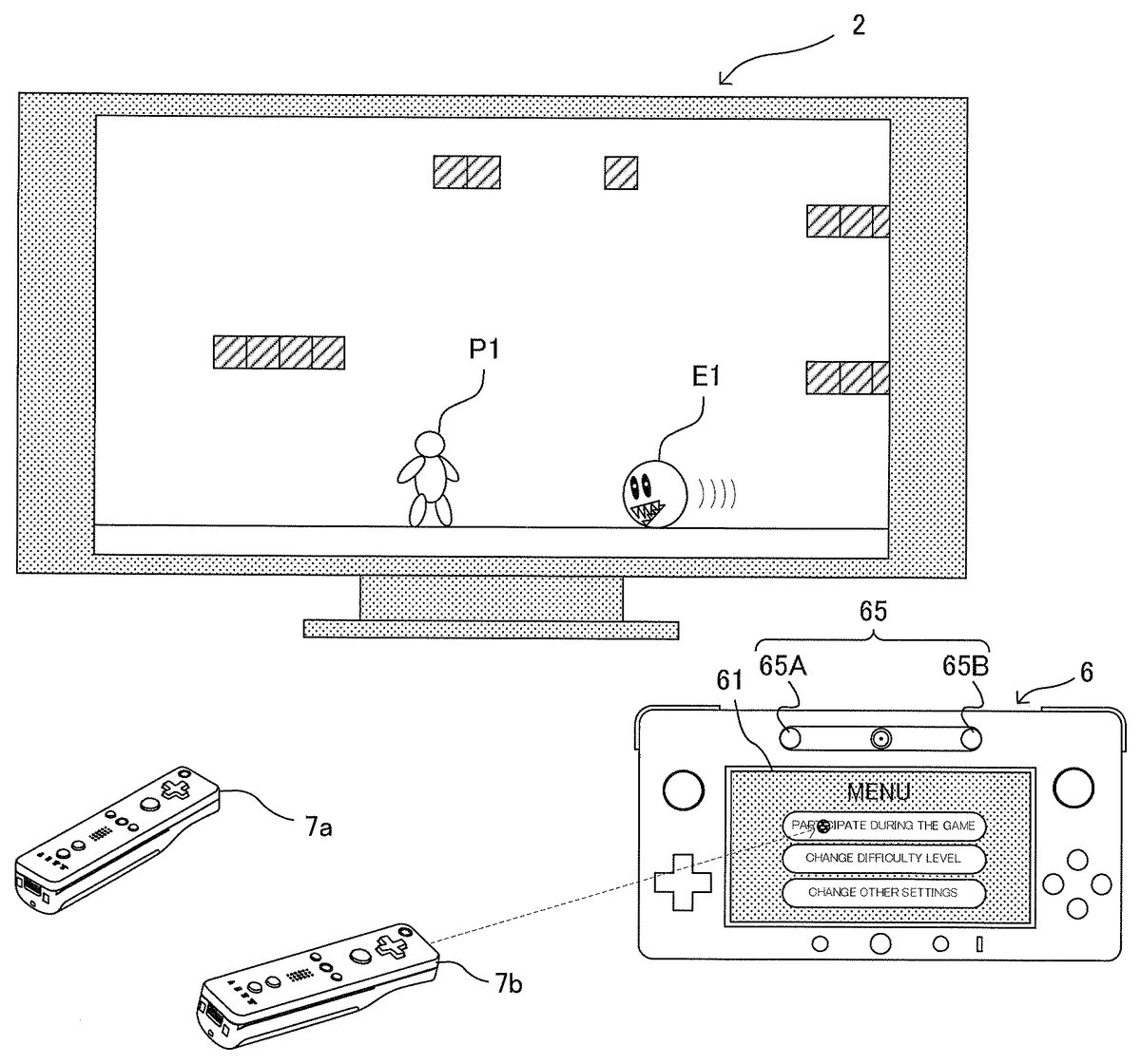
FIG. 6shows an example of a monitor game image displayed on the monitor2when a user (hereinafter referred to as in-play user) is playing by operating a player character P1, using the controller7a. A game world is displayed in the monitor game image. The player character P1, an enemy character E1, and the like exist in the game world. The player character P1is a character operated by the in-play user. The enemy character E1is controlled by a computer based on a predetermined algorithm. The in-play user operates the controller7while viewing the monitor game image displayed on the monitor2.
While the in-play user is playing the game, a terminal game image (setting change image) as shown inFIG. 7is displayed on the LCD61of the terminal device6. Another user (hereinafter referred to as observing user), who is different from the in-play user, can change various settings of the game by operating the terminal device6while viewing the setting change image displayed on the LCD61.
While the in-play user is playing the game, a menu image, which is basically the same as that shown inFIG. 7, is displayed on the LCD61. In another exemplary embodiment, no image may be displayed on the LCD61basically while an in-play user is playing a game, and only after an observing user touches the touch panel62, a menu image as shown inFIG. 7may be displayed.
The menu image shown inFIG. 7displays thee button images B1to B3corresponding to three items, that is, “participate during the game”, “change difficulty level”, and “change other settings”, respectively.
The button image B1is selected when the number of participants in the game is to be changed, that is, when the observing user is to newly participate in the game while the in-play user is playing the game.
The button image B2is selected in the case where, while the in-play user is playing the game, when the observing user is to change the difficulty level of the game.
The button image B3is selected when the observing user is to change other settings of the game (for example, when changing the type of the player character being operated by the in-play user, or when reducing the number of participants in the game).
The observing user can select a button image of a desired item from the menu image, by using the touch panel62. Although details will be described later, the observing user may select a button image of a desired item from the menu image, by using a controller7that is not being used by the in-play user (for example, when the controller7aamong the controllers7ato7dis being used by the in-play user as shown inFIG. 6, one of the controllers7bto7dmay be used). In another exemplary embodiment, a button image of a desired item may be selected from the menu image, by using the operation button64of the terminal device6, or the operation button or the like of a controller7that is not being used by the in-play user.
InFIG. 7, when the observing user touches the button image B1, for example, a character selection image as shown inFIG. 8is displayed on the LCD61. The character selection image shows a plurality of characters C1to C3and the observing user can select a desired character from these characters C1to C3, as a player character that the observing user is to operate. As in the case of the menu image, selection of a character in the character selection image is performed by use of the touch panel62or the like.
When the observing user touches a desired character (for example, character C3), a message instructing the observing user to press a predetermined button (for example, the A button) of the controller7that the observing user is to use when playing the game is displayed on the LCD61as shown inFIG. 9. Causing the observing user to press the predetermined button of the controller7to be used in the game play as described above is an example of a method for allowing the game system to understand which of the controllers7is to be used by the user.
In response to the message shown inFIG. 9, the observing user releases the terminal device6to hold the desired controller (for example, the controller7b) and presses the A button of the controller7b, and then, the character selected in the character selection image (for example, character C3) appears in the game world as a player character P2to be operated by the controller7b, as shown inFIG. 10.
It should be noted that in the exemplary embodiment, as described above, the observing user can select a desired item by using a controller7that is not being used by the in-play user, and can select a desired character. For example, as shown inFIG. 11, the observing user may hold a desired controller among controllers that are not being used by the in-play user (for example, the controller7b), and can give an instruction to “participate during the game” (select a character, or the like) by using the controller7binstead of the touch panel62. In this case, since it is obvious that the observing user attempts to play the game using the controller7b, the confirmation operation as shown inFIG. 9can be omitted. Moreover, the observing user can smoothly participate in the game without doing the action of releasing the terminal device6to hold the controller7b. In the example shown inFIG. 11, the desired item is selected by use of the controller7b, utilizing the marker section65of the terminal device6. However, in another exemplary embodiment, the desired item may be selected by moving a cursor displayed on the LCD61, by means of an operation button of the controller7b.
Although not shown, when the observing user touches the button image B2inFIG. 7, an image for allowing the observing user to select a difficulty level is displayed on the LCD61. Upon a difficulty level being designated by the observing user, the difficulty level of the game being played is switched to the difficulty level updated by the observing user. For example, when the difficulty level is changed to a higher level, the moving speed of the enemy character E1becomes faster from that moment.
It should be noted that inFIG. 7, when the observing user (or one of at least one in-play user) touches the button image B3, he or she can change the type of the player character of an in-play user, or can reduce the number of participants in the game. When the type of the player character operated by an in-play user is to be changed, an image that allows the user to select the player character the type of which the user wants to change, and an image that allows the user to select a desired character are sequentially displayed on the LCD61, for example. When the number of participants in the game is to be reduced, an image that allows a user (the observing user or an in-play user) to select the player character of an in-play user that the user attempts to cause to leave the game is displayed on the LCD61, for example.
In the exemplary embodiment, even while the observing user is changing the settings of the game with reference to the setting change images as shown inFIG. 7toFIG. 9, the progress of the game being played by the in-play user is not suspended. That is, the control of the player character P1based on the operation data from the controller7a, the control of the enemy character E1, and update of the monitor game image are performed without being suspended.
Next, with reference toFIG. 12toFIG. 14, the operation of the game system1for realizing the above game will be described in detail.
FIG. 12shows an example of various data stored in the external main memory12of the game apparatus body5when the above game is performed.
A game program D1is a program for causing the CPU10of the game apparatus body5to perform the game processing for realizing the game. The game program D1is loaded, for example, from the optical disc4to the external main memory12.
Game setting information D2is information of various settings regarding the game (game performance condition). The game setting information D2includes a controller setting, a difficulty level setting, and other settings. The controller setting is information indicating for which player character operations the respective controllers7ato7dare used (in other words, use state of each controller7). The difficulty level setting is information indicating the difficulty level of the game
Controller operation data D3is operation data periodically transmitted by each of the controllers7ato7d.
Marker coordinate data D4is marker coordinate data periodically transmitted by each of the controllers7ato7d. The marker coordinate data D4is coordinate data indicating the position of the marker (the markers65A and65B of the terminal device6) in an image taken by the imaging section of each of the controllers7ato7d.
Terminal operation data D5is operation data periodically transmitted by the terminal device6. As described above, the terminal operation data D5includes the touch position data and the like.
Other data D6is various data used in the game processing, such as image data, the current position of player characters, and the like.
Next, with reference to the flowchart shown inFIG. 13toFIG. 14, the flow of the game processing performed by the CPU10of the game apparatus body5based on the game program D1will be described.
When the game program D1is started, first, in step S10inFIG. 13, the CPU10performs an initialization setting. In the initialization setting, a process of setting the number of participants in the game (the number of participants at the start of the game) based on an instruction from each user, a process of setting the type of a player character operated by each user, a process of setting a difficulty level of the game, a process of arranging the player characters and an enemy character at initial positions in the game world, and the like. Then, the game setting information D2corresponding to the result of the initialization setting is stored in the external main memory12.
In step S11, the CPU10obtains the controller operation data D3and the marker coordinate data D4from each of the controllers7ato7d.
In step S12, the CPU10refers to the controller setting in the game setting information D2and finds a controller7, among the controllers7ato7d, for which an operation target is set (that is, the controller used by an in-play user). Then, based on the controller operation data D3of the controller7for which the operation target is set, the CPU controls the corresponding player character, which is the operation target of the controller7.
In step S13, in accordance with the difficulty level setting in the game setting information D2, the CPU10controls the enemy character based on a predetermined algorithm. For example, the CPU10controls the enemy character such that the higher the difficulty level is, the faster the speed of the enemy character becomes.
In step S14, the CPU10generates a monitor game image. The generated monitor game image is outputted from the game apparatus body5to the monitor2, and is displayed on the monitor2. A part or the whole of the process of generating the monitor game image may be performed by the GPU32in accordance with an instruction from the CPU10.
In step S15, the CPU10obtains the terminal operation data D5from the terminal device6
In step S16, the CPU10refers to the controller setting in the game setting information D2, and finds a controller7, among the controllers7ato7d, for which an operation target is not set (that is a controller not used by the in-play user). Then, based on the terminal operation data D5, and the controller operation data D3and the marker coordinate data D4of the controller7for which an operation target is not set (hereinafter referred to as “the terminal operation data D5and the like”, the CPU10generates a terminal game image (that is, the setting change images shown inFIG. 7toFIG. 9). The generated terminal game image is outputted from the game apparatus body5to the terminal device6, and is displayed on the LCD61of the terminal device6. It should be noted that a part or the whole of the process of generating the terminal game image may be performed by the GPU32in accordance with an instruction from the CPU10.
In step S17, based on the terminal operation data D5and the like, the CPU10determines whether an instruction to participate during the game is inputted by an observing user. When, the instruction to participate during the game has been inputted, the processing advances to step S18, and when the instruction to participate during the game has not been inputted, the processing advances to step S20inFIG. 14.
In step S18, the CPU10updates the controller setting in the game setting information D2in accordance with the instruction to participate during the game from the observing user.
In step S19, the CPU10causes a new player character to appear in the game world in accordance with the instruction to participate during the game from the observing user. Then, the processing advances to step S20inFIG. 14.
After step S18and step S19, the observing user becomes able to operate the player character that has newly appeared in the game world as his or her own player character. That is, the user who has been an observing user becomes a new in-play user.
In step S20inFIG. 14, the CPU10determines whether an instruction to change the difficulty level has been inputted by an observing user, based on the terminal operation data D5and the like. When the instruction to change the difficulty level has been inputted, the processing advances to step S21, and when the instruction to change the difficulty level has not been inputted, the processing advances to step S22.
In step S21, the CPU10updates the difficulty level setting in the game setting information D2in accordance with the instruction to change the difficulty level from the observing user.
In step S22, the CPU10determines whether an instruction to change other settings has been inputted by an observing user, based on the terminal operation data D5and the like. When the instruction to change other settings has been inputted, the processing advances to step S23, and when the instruction to change other settings has not been inputted, the processing advances to step S24.
In step S23, the CPU10updates other settings in the game setting information D2, in accordance with the instruction to change other settings from the observing user.
In step S24, the CPU10determines whether the game has ended. When the game has not ended, the processing returns to step S11inFIG. 13, and when the game has ended, the CPU10ends executing the game program D1.
As described above, according to the exemplary embodiment, it is possible to change the settings of the game, by using a screen (the LCD61) different from the screen (the monitor2) that the in-play user views. Therefore, it is possible to change the settings of the game without hindering the progress of the game being played.
For example, when a new user is to participate in the game while the game is being played, the user can perform selection or the like of a desired character while viewing the character selection image and the like displayed on the LCD61. Therefore, the new user can take time in selecting the desired character without feeling like imposing on the in-play user.
It should be noted that the above exemplary embodiment is merely an example.
For example, in the above exemplary embodiment, the plurality of processes shown inFIG. 13toFIG. 14are performed by one computer (the CPU10). However, in another exemplary embodiment, these processes may be shared by a plurality of computers. In still another exemplary embodiment, some of these processes may be realized by means of a hardware circuit.
In the above exemplary embodiment, the plurality of processes shown inFIG. 13toFIG. 14are performed by one information processing apparatus (the game apparatus body5). However, in another exemplary embodiment, these processes may be shared by a plurality of information processing apparatuses (for example, the game apparatus body5and a server apparatus).
In the above exemplary embodiment, the game program D1is provided from the optical disc4to the game apparatus body5. However, in another exemplary embodiment, the game program D1may be provided from any computer-readable storage medium (for example, CD-ROM, semiconductor memory, or the like) to the game apparatus body5. In still another exemplary embodiment, the game program D1may be stored in advance in a nonvolatile memory (the ROM/RTC13, the flash memory17) in the game apparatus body5. In still another exemplary embodiment, the game program D1may be transmitted from another information processing apparatus (game apparatus or server apparatus) to the game apparatus body5.
The systems, devices and apparatuses described herein may include one or more processors, which may be located in one place or distributed in a variety of places communicating via one or more networks. Such processor(s) can, for example, use conventional 3D graphics transformations, virtual camera and other techniques to provide appropriate images for display. By way of example and without limitation, the processors can be any of: a processor that is part of or is a separate component co-located with the stationary display and which communicates remotely (e.g., wirelessly) with the movable display; or a processor that is part of or is a separate component co-located with the movable display and communicates remotely (e.g., wirelessly) with the stationary display or associated equipment; or a distributed processing arrangement some of which is contained within the movable display housing and some of which is co-located with the stationary display, the distributed portions communicating together via a connection such as a wireless or wired network; or a processor(s) located remotely (e.g., in the cloud) from both the stationary and movable displays and communicating with each of them via one or more network connections; or any combination or variation of the above.
The processors can be implemented using one or more general-purpose processors, one or more specialized graphics processors, or combinations of these. These may be supplemented by specifically-designed ASICs (application specific integrated circuits) and/or logic circuitry. In the case of a distributed processor architecture or arrangement, appropriate data exchange and transmission protocols are used to provide low latency and maintain interactivity, as will be understood by those skilled in the art.
Similarly, program instructions, data and other information for implementing the systems and methods described herein may be stored in one or more on-board and/or removable memory devices. Multiple memory devices may be part of the same device or different devices, which are co-located or remotely located with respect to each other.
While the exemplary embodiments have been described in detail, the foregoing description is in all aspects illustrative and not restrictive. It is understood that numerous other modifications and variations can be devised.
Claims
- A non-transitory computer-readable storage medium having stored therein a game program executed by a computer of a game apparatus, wherein the computer of the game apparatus performs game processing in accordance with a first input from a portable display device that includes an input section and with respective inputs from a plurality of controllers, each of the plurality of controllers used by a different user, generates a game image in accordance with a result of the game processing and causes one display device connected to the game apparatus to display the game image, the game program causing the computer to at least perform: receiving the respective inputs from the plurality of controllers;performing game processing based on the received inputs from the portable display device and the plurality of controllers;generating a game image for common display at a common display device for display to users in accordance with a result of the performed game processing and causing the generated game image for common display to be displayed on the common display device that is different from the portable display device, wherein the common display device is not connected to any of the plurality of controllers;causing, without suspending processes performed during the receiving of the respective inputs, during the game processing, and during the generating a game image, a setting image for changing a setting of the game processing to be displayed on the portable display device;receiving a second input from the input section of the portable display device;and changing a setting of the game processing based on the received second input from the portable display device, wherein the game processing is performed based on a resultant setting due to the setting change, without suspending the processes performed during the receiving the respective inputs from the plurality of controllers, the game processing and the generating a game image, and wherein the setting image is not overlaid on the common game image displayed on the display device that is different from the portable display device.
- The non-transitory computer-readable storage medium according to claim 1 , wherein the changing of the setting changes a game performance condition used in the processes performed by the input receiving, the game processing and the game image generation.
- The non-transitory computer-readable storage medium according to claim 1 , wherein the changing of the setting changes a number of participants in the game.
- The non-transitory computer-readable storage medium according to claim 1 , wherein the changing of the setting increases a number of participants in the game.
- The non-transitory computer-readable storage medium according to claim 4 , wherein the portable display device displays a selection image for allowing a user who attempts to newly participate in the game to select an operation character.
- The non-transitory computer-readable storage medium according to claim 1 , wherein the changing of the setting reduces a number of participants in the game.
- The non-transitory computer-readable storage medium according to claim 6 , wherein the portable display device displays a selection image for allowing a user to select an operation character that the user attempts to cause to leave the game.
- The non-transitory computer-readable storage medium according to claim 1 , wherein the changing of the setting changes an operation character of a user participating in the game.
- The non-transitory computer-readable storage medium according to claim 1 , wherein the changing of the setting changes a difficulty level of the game.
- The non-transitory computer-readable storage medium according to claim 1 , wherein the game processing controls one or more operation characters in a game world based on respective inputs received from the plurality of controllers, and based on information indicating correspondence relationship between the plurality of controllers and the one or more operation characters, and based on the input received by the input section of the portable display device and an input from a controller that is not associated with any of the one or more operation characters, the setting of the game processing is changed.
- The non-transitory computer-readable storage medium according to claim 10 , wherein the changing of the setting increases a number of participants in the game, based on an input from the input device that is not associated with any of the one or more operation characters, and after the number of participants in the game has been increased by the setting change, the game processing performs the game processing also based on the input from the controller that is not associated with any of the one or more operation characters.
- The non-transitory computer-readable storage medium according to claim 1 , wherein the input section of the portable display device includes a pointing device.
- The non-transitory computer-readable storage medium according to claim 1 , wherein the computer causes the setting image to be displayed on the portable display device by wireless transmission.
- The non-transitory computer-readable storage medium according to claim 1 , wherein the computer causes compression of the setting image and outputs a resultant image to the portable display device.
- The non-transitory computer-readable storage medium according to claim 1 , wherein the input section of the portable display device receives an input from a controller not in use for performing the game processing instead of an input from the input section of the portable display device.
- The non-transitory computer-readable storage medium according to claim 1 , wherein the second input from the input section of the portable display device is not to be used for the game processing.
- The non-transitory computer-readable storage medium according to claim 1 , wherein an input from a controller not in use is receivable, as the second input, via the portable display device, and the setting of the game processing is changeable on the basis of the input from the controller not in use.
- The non-transitory computer-readable storage medium according to claim 1 , wherein display of the setting image starts in accordance with starting of the game processing, and the display of the setting image ends in accordance with ending of the game processing.
- A game apparatus that performs game processing in accordance with a first input from a portable display device that includes an input section and with respective inputs from a plurality of controllers, each of the plurality of controllers used by a different user, the game apparatus generating a game image in accordance with a result of the game processing and causing one display device connected to the game apparatus to display the game image and comprising a computer configured to perform at least: receiving the respective inputs from the plurality of controllers;performing game processing based on the received inputs from the portable display device and the plurality of controllers;generating a game image for common display at a common display device for display to users in accordance with a result of the game processing performed by the computer and causing the generated game image for common display to be displayed on the common display device that is different from the portable display device, wherein the common display device is not connected to any of the plurality of controllers;causing, without suspending processes performed during the receiving the respective inputs from the plurality of controllers, the game processing, and the generating a game image, a setting image for changing a setting of the game processing to be displayed on the portable display device;receiving a second input from the input section of the portable display device;and changing a setting of the game processing based on the received second input from the portable display device, wherein the computer performs the game processing based on a resultant setting due to the setting change, without suspending the processes performed during the receiving the respective inputs from the plurality of controllers, the game processing, and the generating a game image, and wherein the setting image is not overlaid on the common game image displayed on the display device that is different from the portable display device.
- A game system that performs game processing in accordance with a first input from a portable display device that includes an input section and with respective inputs from a plurality of controllers, each of the plurality of controllers used by a different user, the game system generating a game image in accordance with a result of the game processing and causing one display device connected to the game system to display the game image and comprising a computer configured to perform at least: receiving the respective inputs from the plurality of controllers;performing game processing based on the received inputs from the portable display device and the plurality of controllers;generating a game image for common display at a common display device for display to users in accordance with a result of the game processing performed by the computer and causing the generated game image for common display to be displayed on the common display device that is different from the portable display device, wherein the common display device is not connected to any of the plurality of controllers;causing, without suspending processes performed during the receiving the respective inputs from the plurality of controllers, the game processing, and the generating a game image, a setting image for changing a setting of the game processing to be displayed on the portable display device;receiving a second input from the input section of the portable display device;and changing a setting of the game processing based on the received second input from the portable display device, wherein the computer performs the game processing based on a resultant setting due to the setting change, without suspending the processes performed during the receiving the respective inputs from the plurality of controllers, the game processing, and the generating a game image, and wherein the setting image is not overlaid on the common game image displayed on the display device that is different from the portable display device.
- A game processing method for performing game processing in accordance with a first input from a portable display device that includes an input section and with respective inputs from a plurality of controllers, each of the plurality of input devices used by a different user, generating a game image in accordance with a result of the game processing and causing one display device connected to a game apparatus to display the game image, the method comprising: receiving the respective inputs from the plurality of input devices;performing game processing, via one or more computer processors, based on the received inputs from the portable display device and the plurality of controllers;generating a game image for common display at a common display device for display to users in accordance with a result of the game processing, wherein the common display device is not connected to any of the plurality of controllers;displaying the generated game image for common display on the common display device that is different from the portable display device;displaying, without suspending the receiving of the respective inputs, the game processing, the generating the game image, and the displaying the game image, a setting image for changing a setting of the game processing on the portable display device;receiving a second input from the input section of the portable display device;and changing a setting of the game processing based on the second input received from the input section, wherein the game processing is performed based on a resultant setting due to the setting change, without suspending the receiving the respective inputs from the plurality of controllers, the game processing, the generating a game image, and the displaying the game image, and wherein the setting image is not overlaid on the common game image displayed on the display device that is different from the portable display device.
- A game apparatus that performs game processing in accordance with a first input from a portable display device for an observing user that includes an input section and with an input from a plurality of controllers, each of the plurality of controllers associated with a respective in-play user, the game apparatus generating a game image in accordance with a result of the game processing and causing one display device connected to the game apparatus to display the game image and comprising a computer configured to at least perform: receiving the respective inputs from the plurality of input devices;performing game processing based on the received inputs from the portable display device and the plurality of controllers;generating a game image for common display at a common display device for display to in-play users in accordance with a result of the performed game processing and causing the generated game image for common display to be displayed on the common display device that is different from the portable display device, wherein the common display device is not connected to any of the plurality of controllers;causing, without suspending processes performed during the receiving of the respective inputs, during the game processing, and during the generating a game image, a setting image for changing a setting of the game processing to be displayed on the portable display device;receiving a second input from the input section of the portable display device;and changing a setting of the game processing based on the received second input from the portable display device, wherein the game processing is performed based on a resultant setting due to the setting change, without suspending the processes performed during the receiving the respective inputs from the plurality of controllers, the game processing and the generating a game image, and wherein the setting image is not overlaid on the common game image displayed on the display device that is different from the portable display device.
Disclaimer: Data collected from the USPTO and may be malformed, incomplete, and/or otherwise inaccurate.