U.S. Pat. No. 9,327,191
METHOD AND APPARATUS FOR ENHANCED VIRTUAL CAMERA CONTROL WITHIN 3D VIDEO GAMES OR OTHER COMPUTER GRAPHICS PRESENTATIONS PROVIDING INTELLIGENT AUTOMATIC 3D-ASSIST FOR THIRD PERSON VIEWPOINTS
AssigneeNINTENDO CO., LTD.
Issue DateMay 8, 2007
Illustrative Figure
Abstract
A pivoting camera viewpoint is provided so that when an animated game character uses a bow and arrow or other weapon, the camera adopts a third person 3D view based on the relative position of the game character and the target that game character is aiming his bow at. The user positions a target cursor on the desired target. This causes an imaginary line segment or plane to be drawn in 3D space between the desired target and the game character (or possibly the game character's bow). The imaginary line segment or plane continues through and past the game character, and the character keeps the weapon, if it is a missile weapon, pointed along this line segment. Additionally, the player can lock onto a target, and freely move a character around. While in lock-on mode, the camera automatically repositions itself to keep both the character and the target visible to a player.
Description
DETAILED DESCRIPTION FIG. 1shows a non-limiting example game system10including a game console100, a television102and a controller107. Game console100executes a game program or other application stored on optical disc104inserted into slot105formed in housing110thereof. The result of the execution of the game program or other application is displayed on display101of television102to which game console100is connected by cable106. Audio associated with the game program or other application is output via speakers109of television102. While an optical disk is shown inFIG. 1, the game program or other application may alternatively or additionally be stored on other storage media such as semiconductor memories, magneto-optical memories, magnetic memories and the like. Controller107wirelessly transmits data such as game control data to the game console100. The game control data may be generated using an operation section of controller107having, for example, a plurality of operation buttons, a direction key and the like. Controller107may also wirelessly receive data transmitted from game console100. Any one of various wireless protocols such as Bluetooth (registered trademark) may be used for the wireless transmissions between controller107and game console100. As discussed below, controller107also includes an imaging information calculation section for capturing and processing images from light-emitting devices108aand108b. Although markers108aand108bare shown inFIG. 1as being above television102, they may also be positioned in other locations, such as below television102. In one implementation, a center point between light-emitting devices108aand108bis substantially aligned with a vertical center-line of television102. The images from light-emitting devices108aand108bcan be used to determine a direction in which controller107is pointing as well as a distance of controller107from display101. By way of example without limitation, light-emitting devices108aand108bmay be implemented as two LED modules (hereinafter, referred to as “markers”) provided in the vicinity of a display screen of television102. The markers each output infrared light and the imaging information calculation section of controller107detects the light output from the LED ...
DETAILED DESCRIPTION
FIG. 1shows a non-limiting example game system10including a game console100, a television102and a controller107.
Game console100executes a game program or other application stored on optical disc104inserted into slot105formed in housing110thereof. The result of the execution of the game program or other application is displayed on display101of television102to which game console100is connected by cable106. Audio associated with the game program or other application is output via speakers109of television102. While an optical disk is shown inFIG. 1, the game program or other application may alternatively or additionally be stored on other storage media such as semiconductor memories, magneto-optical memories, magnetic memories and the like.
Controller107wirelessly transmits data such as game control data to the game console100. The game control data may be generated using an operation section of controller107having, for example, a plurality of operation buttons, a direction key and the like. Controller107may also wirelessly receive data transmitted from game console100. Any one of various wireless protocols such as Bluetooth (registered trademark) may be used for the wireless transmissions between controller107and game console100.
As discussed below, controller107also includes an imaging information calculation section for capturing and processing images from light-emitting devices108aand108b. Although markers108aand108bare shown inFIG. 1as being above television102, they may also be positioned in other locations, such as below television102. In one implementation, a center point between light-emitting devices108aand108bis substantially aligned with a vertical center-line of television102. The images from light-emitting devices108aand108bcan be used to determine a direction in which controller107is pointing as well as a distance of controller107from display101. By way of example without limitation, light-emitting devices108aand108bmay be implemented as two LED modules (hereinafter, referred to as “markers”) provided in the vicinity of a display screen of television102. The markers each output infrared light and the imaging information calculation section of controller107detects the light output from the LED modules to determine a direction in which controller107is pointing and a distance of controller107from display101as mentioned above. As will become apparent from the description below, various implementations of the system and method for simulating the striking of an object described herein do not require use such markers.
With reference to the block diagram ofFIG. 2, game console100includes a RISC central processing unit (CPU)204for executing various types of applications including (but not limited to) video game programs. CPU204executes a boot program stored in a boot ROM (not shown) to initialize game console100and then executes an application (or applications) stored on optical disc104, which is inserted in optical disk drive208. User-accessible eject button210provided on housing110of game console100may be used to eject an optical disk from disk drive208.
In one example implementation, optical disk drive208receives both optical disks of a first type (e.g., of a first size and/or of a first data structure, etc.) containing applications developed to take advantage of the capabilities of CPU204and graphics processor216and optical disks of a second type (e.g., of a second size and/or a second data structure) containing applications originally developed for execution by a CPU and/or graphics processor having capabilities different than those of CPU204and/or graphics processor216. For example, the optical disks of the second type may be applications originally developed for the Nintendo GameCube platform.
CPU204is connected to system LSI202that includes graphics processing unit (GPU)216with an associated graphics memory220, audio digital signal processor (DSP)218, internal main memory222and input/output (I/O) processor224.
I/O processor224of system LSI202is connected to one or more USB ports226, one or more standard memory card slots (connectors)228, WiFi module230, flash memory232and wireless controller module240.
USB ports226are used to connect a wide variety of external devices to game console100. These devices include by way of example without limitation game controllers, keyboards, storage devices such as external hard-disk drives, printers, digital cameras, and the like. USB ports226may also be used for wired network (e.g., LAN) connections. In one example implementation, two USB ports226are provided.
Standard memory card slots (connectors)228are adapted to receive industry-standard-type memory cards (e.g., SD memory cards). In one example implementation, one memory card slot228is provided. These memory cards are generally used as data carriers but of course this use is provided by way of illustration, not limitation. For example, a player may store game data for a particular game on a memory card and bring the memory card to a friend's house to play the game on the friend's game console. The memory cards may also be used to transfer data between the game console and personal computers, digital cameras, and the like.
WiFi module230enables game console100to be connected to a wireless access point. The access point may provide internet connectivity for on-line gaming with players at other locations (with or without voice chat capabilities), as well as web browsing, e-mail, file downloads (including game downloads) and many other types of on-line activities. In some implementations, WiFi module may also be used for communication with other game devices such as suitably-equipped hand-held game devices. Module230is referred to herein as “WiFi”, which is generally a designation used in connection with the family of IEEE 802.11 specifications. However, game console100may of course alternatively or additionally use wireless modules that conform to other wireless standards.
Flash memory232stores, by way of example without limitation, game save data, system files, internal applications for the console and downloaded data (such as games).
Wireless controller module240receives signals wirelessly transmitted from one or more controllers107and provides these received signals to I/O processor224. The signals transmitted by controller107to wireless controller module240may include signals generated by controller107itself as well as by other devices that may be connected to controller107. By way of example, some games may utilize separate right- and left-hand inputs. For such games, another controller (not shown) may be connected to controller107and controller107can transmit to wireless controller module240signals generated by itself and by the other controller.
Wireless controller module240may also wirelessly transmit signals to controller107. By way of example without limitation, controller107(and/or another game controller connected thereto) may be provided with vibration circuitry and vibration circuitry control signals may be sent via wireless controller module240to control the vibration circuitry (e.g., by turning the vibration circuitry on and off). By way of further example without limitation, controller107may be provided with (or be connected to) a speaker (not shown) and audio signals for output from this speaker may be wirelessly communicated to controller107via wireless controller module240. By way of still further example without limitation, controller107may be provided with (or be connected to) a display device (not shown) and display signals for output from this display device may be wirelessly communicated to controller107via wireless controller module240.
Proprietary memory card slots246are adapted to receive proprietary memory cards. In one example implementation, two such slots are provided. These proprietary memory cards have some non-standard feature(s) such as a non-standard connector and/or a non-standard memory architecture. For example, one or more of the memory card slots246may be adapted to receive memory cards used with the Nintendo GameCube platform. In this case, memory cards inserted in such slots can transfer data from games developed for the GameCube platform. In an example implementation, memory card slots246may be used for read-only access to the memory cards inserted therein and limitations may be placed on whether data on these memory cards can be copied or transferred to other storage media such as standard memory cards inserted into slots228.
One or more controller connectors244are adapted for wired connection to respective game controllers. In one example implementation, four such connectors are provided for wired connection to game controllers for the Nintendo GameCube platform. Alternatively, connectors244may be connected to respective wireless receivers that receive signals from wireless game controllers. These connectors enable players, among other things, to use controllers for the Nintendo GameCube platform when an optical disk for a game developed for this platform is inserted into optical disk drive208.
A connector248is provided for connecting game console100to DC power derived, for example, from an ordinary wall outlet. Of course, the power may be derived from one or more batteries.
GPU216performs image processing based on instructions from CPU204. GPU216includes, for example, circuitry for performing calculations necessary for displaying three-dimensional (3D) graphics. GPU216performs image processing using graphics memory220dedicated for image processing and a part of internal main memory222. GPU216generates image data for output to television102by audio/video connector214via audio/video IC (interface)212.
Audio DSP218performs audio processing based on instructions from CPU204. The audio generated by audio DSP218is output to television102by audio/video connector214via audio/video IC212.
External main memory206and internal main memory222are storage areas directly accessible by CPU204. For example, these memories can store an application program such as a game program read from optical disc104by the CPU204, various types of data or the like.
ROM/RTC238includes a real-time clock and preferably runs off of an internal battery (not shown) so as to be usable even if no external power is supplied. ROM/RTC238also may include a boot ROM and SRAM usable by the console.
Power button242is used to power game console100on and off. In one example implementation, power button242must be depressed for a specified time (e.g., one or two seconds) to turn the console off so as to reduce the possibility of inadvertently turn-off. Reset button244is used to reset (re-boot) game console100.
With reference toFIGS. 3 and 4, example controller107includes a housing301on which operating controls302a-302hare provided. Housing301has a generally parallelepiped shape and is sized to be conveniently grasped by a player's hand. Cross-switch302ais provided at the center of a forward part of a top surface of the housing301. Cross-switch302ais a cross-shaped four-direction push switch which includes operation portions corresponding to the directions designated by the arrows (front, rear, right and left), which are respectively located on cross-shaped projecting portions. A player selects one of the front, rear, right and left directions by pressing one of the operation portions of the cross-switch302a. By actuating cross-switch302a, the player can, for example, move a character in different directions in a virtual game world.
Cross-switch302ais described by way of example and other types of operation sections may be used. By way of example without limitation, a composite switch including a push switch with a ring-shaped four-direction operation section and a center switch may be used. By way of further example without limitation, an inclinable stick projecting from the top surface of housing301that outputs signals in accordance with the inclining direction of the stick may be used. By way of still further example without limitation, a horizontally slidable disc-shaped member that outputs signals in accordance with the sliding direction of the disc-shaped member may be used. By way of still further example without limitation, a touch pad may be used. By way of still further example without limitation, separate switches corresponding to at least four directions (e.g., front, rear, right and left) that output respective signals when pressed by a player can be used.
Buttons (or keys)302bthrough302gare provided rearward of cross-switch302aon the top surface of housing301. Buttons302bthrough302gare operation devices that output respective signals when a player presses them. For example, buttons302bthrough302dare respectively a “1” button, a “2” button and an “A” button and buttons302ethrough302gare respectively a “+” key, a menu switch, and a “−” key, for example. Generally, buttons302bthrough302gare assigned various functions in accordance with the application being executed by game console100. In an exemplary arrangement shown inFIG. 3, buttons302bthrough302dare linearly arranged along a front-to-back centerline of the top surface of housing301. Buttons302ethrough302gare linearly arranged along a left-to-right line between buttons302band302d. Button302fmay be recessed from a top surface of housing701to reduce the possibility of inadvertent pressing by a player grasping controller107.
Button302his provided forward of cross-switch302aon the top surface of the housing301. Button302his a power switch for remote on-off switching of the power to game console100. Button302hmay also be recessed from a top surface of housing301to reduce the possibility of inadvertent pressing by a player.
A plurality (e.g., four) of LEDs304is provided rearward of button302con the top surface of housing301. Controller107is assigned a controller type (number) so as to be distinguishable from other controllers used with game console100and LEDs304may be used to provide a player a visual indication of this assigned controller number. For example, when controller107transmits signals to wireless controller module240, one of the plurality of LEDs corresponding to the controller type is lit up.
With reference toFIG. 3B, a recessed portion308is formed on a bottom surface of housing301. Recessed portion308is positioned so as to receive an index finger or middle finger of a player holding controller107. A button302iis provided on a rear, sloped surface308aof the recessed portion. Button302ifunctions, for example, as a “B” button which can be used, by way of illustration, as a trigger switch in a shooting game.
As shown inFIG. 4, an imaging element305ais provided on a front surface of controller housing301. Imaging element305ais part of an imaging information calculation section of controller107that analyzes image data received from markers108aand108b. Imaging information calculation section305has a maximum sampling period of, for example, about 200 frames/sec., and therefore can trace and analyze even relatively fast motion of controller107. The techniques described herein of simulating the striking of an object can be achieved without using information from imaging information calculation section305, and thus further detailed description of the operation of this section is omitted. Additional details may be found in Application No. 60/716,937, entitled “VIDEO GAME SYSTEM WITH WIRELESS MODULAR HANDHELD CONTROLLER,” filed on Sep. 15, 2005; 60/732,648, entitled “INFORMATION PROCESSING PROGRAM,” filed on Nov. 3, 2005; and application No. 60/732,649, entitled “INFORMATION PROCESSING SYSTEM AND PROGRAM THEREFOR,” filed on Nov. 3, 2005. The entire contents of each of these applications are expressly incorporated herein.
Connector303is provided on a rear surface of controller housing301. Connector303is used to connect devices to controller107. For example, a second controller of similar or different configuration may be connected to controller107via connector303in order to allow a player to play games using game control inputs from both hands. Other devices including game controllers for other game consoles, input devices such as keyboards, keypads and touchpads and output devices such as speakers and displays may be connected to controller107using connector303.
For ease of explanation in what follows, a coordinate system for controller107will be defined. As shown inFIGS. 3 and 4, a left-handed X, Y, Z coordinate system has been defined for controller107. Of course, this coordinate system is described by way of example without limitation and the systems and methods described herein are equally applicable when other coordinate systems are used.
As shown in the block diagram ofFIG. 5, controller107includes a three-axis, linear acceleration sensor507that detects linear acceleration in three directions, i.e., the up/down direction (Z-axis shown inFIGS. 3 and 4), the left/right direction (X-axis shown inFIGS. 3 and 4), and the forward/backward direction (Y-axis shown inFIGS. 3 and 4). Alternatively, a two-axis linear accelerometer that only detects linear acceleration along each of the Y-axis and Z-axis may be used or a one-axis linear accelerometer that only detects linear acceleration along the Z-axis may be used. Generally speaking, the accelerometer arrangement (e.g., three-axis or two-axis) will depend on the type of control signals desired. As a non-limiting example, the three-axis or two-axis linear accelerometer may be of the type available from Analog Devices, Inc. or STMicroelectronics N.V. Preferably, acceleration sensor507is an electrostatic capacitance or capacitance-coupling type that is based on silicon micro-machined MEMS (micro-electromechanical systems) technology. However, any other suitable accelerometer technology (e.g., piezoelectric type or piezoresistance type) now existing or later developed may be used to provide three-axis or two-axis linear acceleration sensor507.
As one skilled in the art understands, linear accelerometers, as used in acceleration sensor507, are only capable of detecting acceleration along a straight line corresponding to each axis of the acceleration sensor. In other words, the direct output of acceleration sensor507is limited to signals indicative of linear acceleration (static or dynamic) along each of the two or three axes thereof. As a result, acceleration sensor507cannot directly detect movement along a non-linear (e.g. arcuate) path, rotation, rotational movement, angular displacement, tilt, position, attitude or any other physical characteristic.
However, through additional processing of the linear acceleration signals output from acceleration sensor507, additional information relating to controller107can be inferred or calculated (i.e., determined), as one skilled in the art will readily understand from the description herein. For example, by detecting static, linear acceleration (i.e., gravity), the linear acceleration output of acceleration sensor507can be used to determine tilt of the object relative to the gravity vector by correlating tilt angles with detected linear acceleration. In this way, acceleration sensor507can be used in combination with micro-computer502of controller107(or another processor) to determine tilt, attitude or position of controller107. Similarly, various movements and/or positions of controller107can be calculated through processing of the linear acceleration signals generated by acceleration sensor507when controller107containing acceleration sensor307is subjected to dynamic accelerations by, for example, the hand of a user, as will be explained in detail below.
In another embodiment, acceleration sensor507may include an embedded signal processor or other type of dedicated processor for performing any desired processing of the acceleration signals output from the accelerometers therein prior to outputting signals to micro-computer502. For example, the embedded or dedicated processor could convert the detected acceleration signal to a corresponding tilt angle (or other desired parameter) when the acceleration sensor is intended to detect static acceleration (i.e., gravity).
Returning toFIG. 5, image information calculation section505of controller107includes infrared filter528, lens529, imaging element305aand image processing circuit530. Infrared filter528allows only infrared light to pass therethrough from the light that is incident on the front surface of controller107. Lens529collects and focuses the infrared light from infrared filter528on imaging element305a. Imaging element305ais a solid-state imaging device such as, for example, a CMOS sensor or a CCD. Imaging element305acaptures images of the infrared light from markers108aand108bcollected by lens309. Accordingly, imaging element305acaptures images of only the infrared light that has passed through infrared filter528and generates image data based thereon. This image data is processed by image processing circuit520which detects an area thereof having high brightness, and, based on this detecting, outputs processing result data representing the detected coordinate position and size of the area to communication section506. From this information, the direction in which controller107is pointing and the distance of controller107from display101can be determined.
Vibration circuit512may also be included in controller107. Vibration circuit512may be, for example, a vibration motor or a solenoid. Controller107is vibrated by actuation of the vibration circuit512(e.g., in response to signals from game console100), and the vibration is conveyed to the hand of the player grasping controller107. Thus, a so-called vibration-responsive game may be realized.
As described above, acceleration sensor507detects and outputs the acceleration in the form of components of three axial directions of controller107, i.e., the components of the up-down direction (Z-axis direction), the left-right direction (X-axis direction), and the front-rear direction (the Y-axis direction) of controller107. Data representing the acceleration as the components of the three axial directions detected by acceleration sensor507is output to communication section506. Based on the acceleration data which is output from acceleration sensor507, a motion of controller107can be determined.
Communication section506includes micro-computer502, memory503, wireless module504and antenna505. Micro-computer502controls wireless module504for transmitting and receiving data while using memory503as a storage area during processing. Micro-computer502is supplied with data including operation signals (e.g., cross-switch, button or key data) from operation section302, acceleration signals in the three axial directions (X-axis, Y-axis and Z-axis direction acceleration data) from acceleration sensor507, and processing result data from imaging information calculation section505. Micro-computer502temporarily stores the data supplied thereto in memory503as transmission data for transmission to game console100. The wireless transmission from communication section506to game console100is performed at predetermined time intervals. Because game processing is generally performed at a cycle of 1/60 sec. (16.7 ms), the wireless transmission is preferably performed at a cycle of a shorter time period. For example, a communication section structured using Bluetooth (registered trademark) technology can have a cycle of 5 ms. At the transmission time, micro-computer502outputs the transmission data stored in memory503as a series of operation information to wireless module504. Wireless module504uses, for example, Bluetooth (registered trademark) technology to send the operation information from antenna505as a carrier wave signal having a specified frequency. Thus, operation signal data from operation section302, the X-axis, Y-axis and Z-axis direction acceleration data from acceleration sensor507, and the processing result data from imaging information calculation section505are transmitted from controller107. Game console100receives the carrier wave signal and demodulates or decodes the carrier wave signal to obtain the operation information (e.g., the operation signal data, the X-axis, Y-axis and Z-axis direction acceleration data, and the processing result data). Based on this received data and the application currently being executed, CPU204of game console100performs application processing. If communication section506is structured using Bluetooth (registered trademark) technology, controller107can also receive data wirelessly transmitted thereto from devices including game console100.
Example Virtual Camera Control
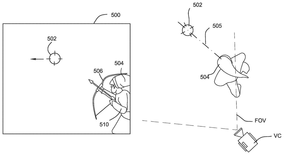
FIGS. 6, 7, 8, 9, 10 and 11show one example illustrative non-limiting implementation of how a virtual camera can be automatically controlled to provide different third person perspectives based on for example the position of a targeting marker502. Referring toFIG. 6, a 3D image500of the type to be displayed on a television screen, liquid crystal display, or any other display as described above is shown. This 3D image500may show a rich and varied 3D landscape including buildings, animated characters, mountains, castles, or any other desired objects with shading, texture mapping and other rich complexity. In the example shown, for purposes of simplification of illustration and explanation, however, all that is shown in image500is a targeting marker502and an animated game character504holding on to a weapon506(in this case a bow and arrow).
In this particular example, the game player provides inputs to the video game system to control the position of targeting marker502. The game player may control the position of targeting marker502by any convenient means such as by tilting handheld controller as described above, moving a joystick, moving a stylus in contact with a touch screen, or any other convenient method. As the game player moves targeting marker502, the video game system automatically animates character504so that the character turns toward the targeting marker and the character's weapon506is always pointing toward the targeting marker. In this way, the game player selects where animated game character504is aiming his weapon506.
For example, if the game player positions targeting marker502directly above a displayed enemy (not shown) within a 3D scene, then animated character504is controlled to automatically aim his weapon506at the targeting marker and thus at the enemy. In this exemplary illustrative non-limiting implementation, targeting marker502is displayed as if it were positioned on a virtual reticle or other 2D overlay in front of the entire scene. However, in other exemplary illustrative non-limiting implementations, the targeting marker502could be a laser pointer, a tracer bullet, or any other indicator within the 3D scene itself.
Image500is “captured” from the perspective of a virtual camera VC also located within the same 3D world as character504. SeeFIG. 6A. In theFIG. 6example shown, the virtual camera is surveying the 3D scene as if the camera is looking over the right shoulder508of animated character504. In this particular instance, the aiming direction for the animated game character504may actually be indicated by a vector drawn from the virtual camera VC through the targeting marker502toward infinity within the 3D scene. Alternatively, as another example, the aiming direction can be indicated by a vector505drawn through the centroid of the character and passing through the targeting marker. Wherever the game player positions targeting marker504within the 3D scene is the place that game character504automatically aims his weapon506. The game player may actuate the weapon506(e.g., by pressing or releasing a button, pulling or releasing a trigger or joystick or the like) to animate game character504to fire the weapon506(in this case, letting an arrow fly toward the enemy marked by targeting marker502).
FIG. 7shows another exemplary image500after the game player has used inputs to move the targeting marker502to the left. In this case, the virtual camera VC is still positioned to view the 3D scene over the animated game character's right shoulder508, the weapon506continues to be aimed at (and follows) the targeting marker502, and the animated game character504is automatically animated to turn slightly to the left in order to change his aim so that weapon506is directed at the targeting marker. SeeFIG. 7A. The character's aim, in one exemplary implementation, follows a vector505from the centroid of the character through the targeting marker.
FIG. 8shows the 3D image as the game player continues to move the targeting marker502leftward in the scene. In this particular instance, the targeting marker502is now aimed directly in front of animated character504. In other words, the game player desires the animated game character504to aim his weapon506directly in front of him—and the animated game character504is now positioned between the game player's virtual viewpoint (from the perspective of the virtual camera) and the desired target the game player has indicated by the targeting marker502. Note that the virtual camera's perspective remains the same—the game player continues to look into the 3D scene over the animated character's right shoulder508. SeeFIG. 8A.
In this particular exemplary illustrative non-limiting implementation, the targeting marker502is shown positioned “on” the game character504itself so that that game player does not lose sight of the targeting marker502. As discussed above, however, other arrangements are possible.
FIG. 9shows an example view as the game player continues to move targeting marker leftward to “cross” the game character504and come to rest at a position that is now to the left of the animated game character504within the 3D scene. In this particular example, as the targeting marker502crosses an imaginary plane extending through and in a direction toward the “front” of the game character504(e.g., relative to the current virtual camera position), the position of the virtual camera and/or its viewing direction or field of view shifts rapidly.FIG. 9, 9Ashows that the virtual camera VC has moved in position and/or direction relative to theFIG. 8, 8Aposition. Note that the virtual position of game character504within the 3D world has not changed betweenFIG. 8andFIG. 9—all that the animated game character has done is to pivot or rotate to the left in order to follow the targeting marker502. However, the game play shown provides a different virtual camera position as the targeting marker has moved from the right to the left “crossing” the game character504relative to the virtual camera's field of view—so that the game player now feels as if he is watching the 3D scene from a position standing to the animated game character's left-hand side and looking over the character's left shoulder510.
In one exemplary illustrative non-limiting implementation, a virtual invisible plane may be defined between the virtual camera VC and the centroid of the game character504. As the targeting marker502passes through that virtual plane, the virtual camera VC changes position by moving and/or pivoting to the left so that it is now viewing the 3D scene over the game character's left shoulder510. In one exemplary illustrative non-limiting implementation, the transition between theFIG. 8viewpoint and theFIG. 9viewpoint can be very rapid. The effect is similar to a cinematography effect where the camera has pivoted or swung very rapidly to give the viewer has the best viewpoint of the action. The rapid pivoting of the virtual camera is not distracting but actually feels very natural from the game player's perspective since the average game player has been exposed to rapid shifts in camera angle based on viewing modern action films.
In an alternative exemplary illustrative non-limiting implementation, the camera location and the on-screen character position are fixed when the character is in this free-targeting mode (i.e. the player can move the targeting marker wherever desired). In this exemplary implementation, the character504is fixed in a lower left or right hand corner (e.g. one of the positions shown inFIGS. 6-11). No matter where the player aims the targeting marker502, the character's location will not change. The character504may move a weapon506to continue to aim at the targeting marker502, but the character504itself does not change location. If, for example, the character is positioned as inFIG. 8, then moving the targeting marker to the far left of the screen will not produce the scene shown inFIG. 9. Rather, the targeting marker will simply be positioned to the far left of the screen, visible above the character's shoulders or imposed on the character itself, depending on targeting marker vertical positioning.
According to this implementation, if the player wishes to view a different portion of the world to select a target, the player uses a control other than that controlling the targeting marker (e.g. an analog joystick) to turn the direction in which the character faces. This allows the character to spin a full 360 degrees although the entire time the camera remains over the character's right shoulder (in this example).
In both of these exemplary implementations, the character continues to aim along a vector505passing through the character's504centroid and through the targeting marker502.
FIG. 10shows an example image500in which the game player has moved the targeting marker502slightly to the right relative to itsFIG. 9position in order to change the direction animated game character504is aiming his weapon506. In the exemplary illustrative non-limiting implementation, the game player may move targeting marker502over a wide range within the 3D scene. As long as he does not cross the position of the game character with the targeting marker, the virtual camera position will remain the same (although the virtual camera may still change other parameters such as azimuth and/or inclination to always keep the targeting marker and the associated target within view). In some exemplary illustrative non-limiting implementations, the direction in which the virtual camera is aiming may also change to follow the targeting marker502so that, depending on virtual zoom and other factors, the targeting marker (and thus the object the animated game character's weapon506is aimed at) always remains within the virtual camera's field of view.
As the game player continues to move the targeting marker502rightward, the targeting marker will eventually cross the line between the virtual camera position and the centroid of the virtual character504. At this point, the virtual camera position automatically shifts again so the game player feels as if he is again viewing the 3D scene over the game character's right shoulder508rather than his left shoulder. This is shown in the transition betweenFIGS. 10 and 11(see alsoFIGS. 10A and 11A).
FIGS. 12A-12Dshow exemplary illustrative non-limiting displays of a character shifting from a “movement” mode to a “free targeting” mode. According to these exemplary implementations, a player controlled cursor760is shown flying in a position on the screen. In this exemplary implementation, the position of the cursor760can be changed using the same control that the player would use to move the targeting marker in the free targeting mode. Thus, for example, the player could preposition the targeting marker in the movement mode before switching into the free targeting mode.
FIGS. 12A and 12Care the same exemplary displays, except that the cursor760has moved from the character's right side in12A to the character's left side in12C. According to this exemplary implementation, the relative position of the cursor to the character when the targeting mode is selected determines at which screen side the character is positioned. TheFIG. 12Adisplayed scene changes to theFIG. 12Bdisplayed scene once a free targeting mode is activated, since the cursor is on the character's right side. Similarly, theFIG. 12Cscene becomes theFIG. 12Dscene once a free targeting mode is activated, since the cursor is on the character's left side. In eitherFIG. 12B or 12D, the character has not actually moved positions, rather the player is shown the scene over the character's shoulder that was on the same side as the cursor.
In this exemplary implementation, such a system allows the player to “pre-designate” which side of the screen the character will be set to, as well as which side of the screen will be shown, all through the use of a single input in the exemplary illustrative non-limiting implementation. For example, if two enemies are charging the player, from the left and from the right, but the right-most enemy is closer, the player can position the cursor over the closer enemy and trigger the free targeting mode. Since the perspective will shift so the character is placed in the lower left corner, the player has a clearer view of a wider area of the right half of the previous movement mode screen. The player can then target the closer enemy, kill it, shift back to movement mode, place the cursor over the remaining enemy and trigger the free targeting mode again.
Since in this exemplary implementation, the free targeting mode is triggered by the same button, regardless of the resultant character position, the player can worry less about designating the proper input to place a camera in one position or another and focus more on playing the game. The action becomes very intuitive. The player simply places the cursor over what he wishes to attack in movement mode, triggers free targeting mode, and the camera is automatically placed in a proper position allowing optimal view of the approaching designated target or designated area.
FIG. 13shows an example flowchart of program control steps used by theFIG. 1system to generate scenes wherein a targeting marker passing from a character's first side to second side causes a shift in displayed character position (i.e. the character display is swapped from one camera to another and the character moves from a lower first corner to a lower second corner). In this particular illustrative non-limiting example, the 3D scene is displayed from a particular virtual camera position and then user input is detected (blocks602,604). The targeting marker502is displayed as a position corresponding to user input (block604). The system then detects whether the targeting marker crosses the game character (e.g., by performing a plane test as discussed above, or by any other means) (decision block606). If the test reveals that the targeting marker has “crossed” the game character (“yes” exit to decision block606), then the position and/or direction and/or other parameter associated with the virtual camera VC is shifted or pivoted (block608) and the scene is redisplayed from the new viewpoint (block602). This process continues for the duration of game play.
FIG. 14shows an example flowchart of program control steps used by theFIG. 1system to generate scenes wherein a player is first displayed in a movement mode and then subsequently switches into a free targeting mode. According to this exemplary illustrative non-limiting implementation, a 3D scene is displayed showing the character free to move about in the game world (block610). The system then detects whether a user has indicated a desire to switch into a free targeting mode (decision block612). If so, the system must determine whether the character is to be rendered in a lower left or lower right corner (at least according to this example, although other positions could be available).
To determine which corner the character is rendered in, the system detects whether the displayed cursor is to the right of the character or not (decision block614). While it would also be possible to subsequently determine if the cursor was to the left of the character or not, in this example it is assumed that if the cursor is not to the right of the character, then it must be to the left of the character. If the cursor is to the right of the character, the character is displayed in a lower left screen corner (block616). Alternatively, if the cursor is not to the character's right, the character is displayed in a lower right screen corner (block618). From either display, rotational input and/or targeting marker control are detected (block620). Additionally, the system checks to ensure that targeting is still desired (decision block622). If targeting is no longer selected at some point, then the system can return to display the character in a movement mode. As long as targeting is still selected, however, the system checks to see whether the character is in a lower left corner (decision block624) and then branches to block616or618depending on the result, allowing a new check for different input.
FIG. 15shows another exemplary illustrative non-limiting example of game play effects in which the game player can designate an enemy or object to attack or otherwise interact with by moving a targeting marker or other indicator to a particular enemy or other object and then providing a control input that causes the game to “lock on” to that particular target700. The animated game character504may now attack the target700(e.g., by directing a sword fight toward it, or shooting it with a selected missile weapon). In this way, the game player can select between a number of different enemies or other objects for the game player504to attack, and the game animation automatically animates the game character504to attack the target the game player has “locked on” to. Note that “locking on” may not necessarily be in the sense of defining a field of view that aims or focuses on the “locked on” target. For example, such “locking on” can in some exemplary illustrative non-limiting implementations simply designate a particular object that the game character504is to attack. A third person (or other) viewpoint can then be used to observe the attack.
FIGS. 16A-16Dshow a plurality of exemplary third person viewpoints when a game is in a lock-on targeting mode according to an exemplary illustrative non-limiting implementation.
FIG. 16Ashows an overhead view not necessarily seen in the game in this exemplary implementation but described here for purposes of illustration and clarity. A character504is displayed at a variety of positions B, C and D around a target dummy702. According to this exemplary implementation, once the character504has locked-on to the target702, the character can be freely moved within the game space. Here, the character is shown rotating from a position B where the camera504is looking over the character's right shoulder to a position C 90° away, to a position D almost 180° away. At each position B, C and D, the character504remains facing the target702and the character's weapon is aimed at the target along a vector (not shown) from the character's centroid through the target. While no targeting marker is provided according to this exemplary implementation, a marker701indicating the selected target may be shown, allowing the player to easily determine which target is locked in.
FIG. 16Bshows an exemplary screen that might be shown if the character504is in position B. Here, the character is shown to the left and in the foreground with respect to the target702. The marker701indicating target selection may also be shown.
FIG. 16Cshows a second exemplary screen that might be shown if the character has moved to position C. Returning toFIG. 16A, an exemplary control800for moving the character is shown. Analog joystick802can be moved freely to cause the character to move in a corresponding direction. In this exemplary implementation, the joystick has been rotated along the arrow804, indicating a desire to have the character perform a similar rotation about the target702. InFIG. 16C, the character has moved approximately half-way to position D, although the camera position remains relatively unchanged. The character and the target are both shown approximately equidistant from the camera, in this implementation. While the camera may pan in or out to keep both the character and the target shown on the screen, the camera remains generally stationary until the character reaches position D.
FIG. 16Dshows a third exemplary screen that might be shown if the character has reached position D. Here the character is almost opposite the camera position, but has not quite reached 180° away. Now the target appears to be in the foreground relative to the character, and the character is about to pass behind the target. While the target is smaller in size than the character in this exemplary display, it would be possible for a character to be attacking a target that is much larger than the character. If this were the case, then the character moving behind the target could obscure the player's view of the character. Thus, in this exemplary implementation, when the character has reached position D, the camera begins to rotate around the target in the direction that the character is moving, and thus the screen shown inFIG. 16Dis maintained as long as the character continues to rotate in the direction804indicated by the exemplary controller800.
Although the screen will typically maintain the display ofFIG. 16Dwhen a character has reached a position approximately opposite the camera and continues to move in a rotational direction around the target, it is possible for a user to manipulate a controller such that the character does pass behind the target and such that the target does obstruct the view of the character. This effect may also occur with a moving target (as opposed to the stationary one shown here), since the target may pass in front of the character and between the camera during its motion. In that instance, the camera view would quickly switch to almost a mirror image of the view shown inFIG. 16D, placing the target on a left side of the character. If the path of rotation continued, the camera could then remain fixed and the character would rotate to a position opposite position C (and a display that was the mirror ofFIG. 16Cmight be shown) and then rotate to a position close to that of position B (and a display that was the mirror ofFIG. 16Bmight be shown, with the camera looking over the character's left shoulder. Such fast switching allows the character to be obscured for only a limited period of time if it moves behind a target. At the same time, once the new camera position is obtained, if the character is moving in the same direction, then the relatively stationary position of the new camera allows the player to sort out the shift and observe the scene containing both the character and the target, now on opposite sides.
In the automatic camera positioning of this exemplary implementation, the camera's automatic following of the character at a point just before the character would be obscured allows the player to constantly see the character. Thus, instead of having to manually adjust the camera to show various perspective, the simple rotation of the camera to keep the player shown frees up the player's concentration of focus on attacking the enemy. Since this exemplary implementation also chooses a view that shows both character and target, players don't have to be concerned about selecting an improper camera view at a critical moment of a fight and thus being unable to see the character. Rather, by allowing game controlled camera motion, the player can rely on the game to show a proper and useful view.
FIGS. 17A-17Cshow another plurality of exemplary third person viewpoints when a game is in a lock on targeting mode according to an exemplary illustrative non-limiting implementation. In these exemplary viewpoints, the player moves the character504from a position B′ to the left of a target702to a position C′ to the right of a target702across an invisible center plane720.
FIG. 17Bshows an exemplary initial position wherein the character504is at a position B′ to the left of a target702. The character is shown from a perspective over the character's right shoulder by camera750. Here, as the character moves towards a center plane720, the camera750may move with the character, so as to attempt to prevent the character from passing in front of the camera and completely obscuring the target. Although the camera is moving with the character504in this exemplary illustrative non-limiting implementation, as the character504approaches a center plane720the camera750is moving slower than the character, so the character begins to obscure the target. Once the character504reaches the center plane720, the character briefly blocks the target view and then passes over the plane720. On the other side of the center plane, the camera750switches to a view over the character's opposite shoulder, placing the target702on the left and the character504on the right. This helps minimize character obstruction of the target, since the character is moving to the right and the target is now displayed on the character's left side.
In another exemplary illustrative non-limiting implementation, the camera750remains relatively fixed as the character504moves between the camera750and the target702towards the central plane720. Since the camera can be place near the central plane, the character will still only obscure the view of the target for a short period of time before crossing the central plane, at which point the view would switch to the view from the other camera position, also near the central plane.
FIG. 17Cshows an exemplary position where a character504has moved from position B′ to position C′ across plane720. The camera750is now positioned over the character's left shoulder and shows the target702on the left side of the character504. Such switching allows the player to move the character back and forth in front of the enemy and not have to worry about obscuring the enemy from view.
Also shown withFIG. 17Ais exemplary controller800, with joystick802having been moved in direction804directing the character movement depicted in these exemplary screens.
In this exemplary implementation, automatic camera decision making saves the player from being forced to manually switch a camera when the character crosses in front of a target. The scene would potentially appear awkward if the camera remained in a position over the character's right shoulder while the character was on the right side of the screen, since the target may then be obscured by some or all of the character's body. Instead of forcing the player to manually change the perspective, the camera simply keeps proper sight-lines established by switching shoulders over which it looks as the character crosses a center plane of the target. In this exemplary implementation the center plane is determined by the target, not the center of the screen, allowing the player to ensure that, because of camera swapping, the character should obscure the target for a very limited time, if any. This way, even if the target has moved away from the center of the screen, the player's view of it will remain correct as the character passes across a center plane of the target.
Since the camera makes correct automatic adjustments according to this illustrative implementation, a player can freely run back and forth in front of a foe and focus on the enemy, rather than on the camera-work.
FIGS. 18A-18Dshow a plurality of exemplary viewpoints of a character shown by a camera when a player has ceased to direct a character motion in a particular direction. As shown inFIGS. 16A-16D, when a game is placed in a lock on mode, a character can move freely around a target position, and continues to do so as long as a directional controller (shown in16A) directs such movement. When the player stops directing character movement, however, it may be that a character is left in a position whereby additional movement could make it difficult for a player to keep track of a locked on target. One exemplary illustrative non-limiting implementation of automatic camera movement is shown in these FIGS., the movement being designed to help better show both a character and a target on-screen at the same time.
InFIG. 18A, portions of the approximately 180° arc along which a player may move to one side of a target are grayed out. While these areas are only exemplary, in this exemplary implementation roughly the back 90°724and the front most 10°722are grayed out. According to this exemplary implementation, if the character is within either of these areas722,724and the player stops directing the character motion, the camera750will auto adjust to one of two “static” positions B″ or D″ respectively. The character is also shown in a position C″, but from this position, since the character is closer to the camera than the target and not in danger of obscuring the target, the camera will simply show the character where it is left by the player.
FIG. 18Bshows an exemplary scene of a forward “static” position of a camera. Here, the player presumably stopped moving the character while the character was in position F, which was within the forward grey area722. Since the character was possibly obscuring part of the target in this position, the camera automatically shifts to position B″, thus showing the character504on the right side of the screen and the target702on the left side of the screen, with neither one obscured. The camera shift speed may depend on a variety of factors and can be varied as needed for a particular game.
FIG. 18Cshows an exemplary scene of a “shift-free” zone, wherein the player can freely move and leave the character504. Here, the character is closer to the camera than the target702, and to well the left of the target. In this area, when the player stops directing character movement, the scene remains relatively the same (slight camera shifts may occur to account for terrain or other potential obstacles). The size of this zone can also vary with the relative character and target sizes, as well as varying with the proximity of the character to the target. For example, if the character were attacking a very small target at very close proximity, then position B″ and most positions from B″ to D″ might not be desirable as the character may obscure portions, if not all, of the target. In this instance, the camera may automatically shift to position D″, where the character and target are shown at opposite positions and a similar depth, to avoid possibly obscuring the target.
FIG. 18Dshows an exemplary rearward “static” position of a camera. In this exemplary implementation, the player stopped moving the character while it was at a position E. Since the character was in the background at this point, the camera automatically adjusts to bring the character to an “even” position with the target, thus placing the character in the foreground again. This way, if a character is running behind a target to attack a tail or rear weak spot, and then the player desires to focus attention on attacking that area, the player can release the control designating movement around the target and have the view rotated such that a previously hidden rear portion of the target onto which the character was locked is now displayed oppositional to the character and in plain sight. Thus, if a target had multiple zones for attacking, the player could lock onto an appropriate zone and focus on moving the character into position for the attack and then release the movement designation control and focus efforts on attacking the now shown portion. These automatic camera shifts help keep the action and locked-on target visible to a player when the character is not maneuvering for position.
FIG. 19shows an exemplary flow chart for camera control decisions while a game is in lock on mode. After beginning lock on mode (block801) the game must determine in which initial position to display the character. If the character is, in the movement mode, to the right of the central plane (decision block803) then the game displays the character in lock on with the initial camera over the character's left shoulder (block830), else the game displays the character with the camera over the character's right shoulder (block805). In this exemplary flow chart, all displays shown in blocks on the left half of the chart are done with the camera between an object and a character left of an object (i.e. camera over the character's right shoulder), and all displays on the right half of the chart are done with the camera between an object and a character to the right of an object. Crossing over from the right side to the left, or vice versa, means that the character has crossed the center plane and the camera has switched positions to the corresponding position listed above. Additionally, according to this illustrative exemplary non-limiting implementation, regardless of where the player is in the movement mode before entering lock on mode (for example, a character can be completely blocked by a potential target object in the moving view), once lock on is selected the camera rotates to a position similar to that shown inFIG. 18B(or the mirror image of that FIG., depending on which side the character is on). Different initial starting positions could be used, however.
After displaying the character in initial position with the camera over the right shoulder (block805), the game checks to see if the player directed character movement (decision block806). If the player did direct movement, the game must then determine if the movement was rightward or not (decision block808) (forward and backward movement do not generally cause camera movement in lock-on mode except zooms to prevent character from moving offscreen, although additional camera motion could be applied for these character movements).
If the character was moved right, the game displays the character moving to his right (block810) and then checks to see if the character crosses over the central plane (decision block812). If the character does not cross over the central plane, the game checks for continued movement indication (block806), but if the character does cross over the central plane then the camera perspective changes and the character is shown moving to his right still (block840), but with the camera now over his left shoulder and the target on the left side of the screen.
If the character was not moved right (at decision block808) then the character is shown moving to his left (block814). The game must then determine if the turning point was reached (decision block816). If not, then the game returns to checking for movement (decision block806). If the turning point was reached, then the camera itself begins to shift left around the target (block818) as the character continues to move in that direction. This has the effect of causing the scene to rotate, preventing the character from moving behind the target (although the character can still be maneuvered behind the target, such maneuvering just may take extra work). As the camera is shifted (block818) the game must also determine if the central plane has been crossed behind the target (decision block820). If the plane has not been crossed, the game returns to detecting movement (decision block806), but if the plane is crossed then the character continues to be displayed moving left (block836) only from the other camera position, such that the target is now on the left side of the screen In this instance, since the character is opposite the camera and facing the camera, the target is on the screen's left side, while the character moves to his left (or the screen's right side).
If no character motion is detected at decision block806, then the game must determine if the camera needs to be automatically moved to a better position. First, the game checks to see if the character is in a “shift-free” zone (decision block822) (such as the exemplary zone between positions B″ and D″ shown inFIG. 18A). If the character is in such a zone, the camera does not shift, but rather shows the scene as is and returns to checking for movement (decision block806). If the character is not in a shift-free zone, then the camera must determine if the character is in the rear zone (decision block824). If the character is in the rear zone, then the camera is shifted left around the target by some degree (block826), otherwise, the camera is shifted right around the target by some degree (block828). In either case, the entire shift does not have to take place at this point, the camera may be moved by a small amount and then the game can check for movement again (decision block806). In this way, the camera may only return to a “static” position if the character is left unmoved for several cycles of this determination/move.
Alternatively, after displaying the character in initial position with the camera over the left shoulder (block830), the game checks to see if the player directed character movement (decision block832). If the player did direct movement, the game must then determine if the movement was leftward or not (decision block834) (forward and backward movement do not generally cause camera movement in lock-on mode except zooms to prevent character from moving offscreen, although additional motion could be applied for these movements).
If the character was moved left, the game displays the character moving to his left (block836) and then checks to see if the character crosses over the central plane (decision block838). If the character does not cross over the central plane, the game checks for continued movement indication (block832), but if the character does cross over the central plane then the camera perspective changes and the character is shown moving to his left still (block814), but with the camera now over his right shoulder and the target on the right side of the screen.
If the character was not moved left (at decision block832) then the character is shown moving to his right (block840). The game must then determine if the turning point was reached (decision block842). If not, then the game returns to checking for movement (decision block832). If the turning point was reached, then the camera itself begins to shift right around the target (block844) as the character continues to move in that direction. This has the effect of causing the scene to rotate, preventing the character from moving behind the target (although the character can still be maneuvered behind the target, such maneuvering just may take extra work). As the camera is shifted (block844) the game must also determine if the central plane has been crossed behind the target (decision block846). If the plane has not been crossed, the game returns to detecting movement (decision block832), but if the plane is crossed then the character continues to be displayed moving right (block810) only from the other camera position, such that the target is now on the right side of the screen In this instance, since the character is opposite the camera and facing the camera, the target is on the screen's right side, while the character moves to his right (or the screen's left side).
If no character motion is detected at decision block832, then the game must determine if the camera needs to be automatically moved to a better position. First, the game checks to see if the character is in a “shift-free” zone (decision block848) (such as the exemplary zone shown between positions B″ and D″ inFIG. 18A). If the character is in such a zone, the camera does not shift, but rather shows the scene as is and returns to checking for movement (decision block832). If the character is not in a shift-free zone, then the camera must determine if the character is in the rear zone (decision block850). If the character is in the rear zone, then the camera is shifted right around the target by some degree (block852), otherwise, the camera is shifted left around the target by some degree (block854). In either case, the entire shift does not have to take place at this point, the camera may be moved by a small amount and then the game can check for movement again (decision block832).
While the systems and methods have been described in connection with what is presently considered to practical and preferred embodiments, it is to be understood that these systems and methods are not limited to the disclosed embodiments, but on the contrary, is intended to cover various modifications and equivalent arrangements included within the scope of the appended claims.
Claims
- A method of using at least one hardware processor for specifying a virtual camera position in a virtual 3-D space, the method comprising: displaying, to a screen of a display device, a 3-D space from the perspective of the virtual camera, the displayed 3-D space including a virtual game character;detecting at least one pointing input that is controllable by a player, detecting a user input indicating initiation of a free targeting mode;controlling said game character to assume an aiming position in accordance with initiation of the free targeting mode;controlling, using the least one hardware processor, said game character to aim at a location or in a direction within the 3-D space in accordance with the at least one pointing input;displaying, in accordance with the at least one pointing input, a targeting marker at a location(s) on the display area;determining where the targeting marker is located relative to where the game character is shown on the screen of the display device;and automatically selecting, using the at least one processor, between a first perspective and a second perspective different from said first perspective for viewing said game character in said aiming position as a result of determining the targeting marker overlaps where the video game character is displayed on the screen of the display device.
- The method of claim 1 , wherein the determining also determines if the pointing input is on aright side or a left side of the virtual game character, the method further comprising: displaying a first perspective of the 3-D space in accordance with the determined left side, wherein the virtual game character is fixedly positioned in a first aiming position;and displaying a second perspective of the 3-D space different from said first perspective in accordance with the determined right side, wherein the virtual game character is fixedly positioned in a second aiming position different from the first aiming position.
- The method of claim 2 , wherein the first aiming position is displayed in the substantially lower right corner of the screen of the display device and the second aiming position is the substantially lower left corner of the screen.
- The method of claim 2 , further comprising: accepting player provided input to freely control the pointing input while the first and/or second perspectives are displayed;displaying a virtual character-held object in accordance with the pointing input.
- The method of claim 4 , further comprising: while the first perspective is displayed, determining if the targeting marker is moved past a predetermined right-wards position in the 3-D space;and if the targeting marker is determined to have moved past the predetermined right-wards position, displaying the second perspective of the 3-D space.
- The method of claim 4 , further comprising: while the second perspective is displayed, determining if the targeting marker is moved past a predetermined left-wards position in the 3-D space;and if the targeting marker is determined to have moved past the predetermined left-wards position, displaying the first perspective of the 3-D space.
- The method of claim 6 , wherein the predetermined left-wards position corresponds to a virtual plane running down a vertical center of the virtual game character.
- A non-transitory computer readable storage medium storing instructions for positioning and/or orienting a virtual camera in a virtual three-dimensional (3D) world on a computing system that includes at least one processor, the stored instructions comprising instructions, when executed by the at least one processor, configured to cause the computing system to: output a first image to a display device that is based on a first view perspective of a virtual 3D world provided via the virtual camera, the first view perspective including a virtual object that is located within the virtual 3D world;receive a first user input that indicates a first position on the display device and within the first image displayed thereon;output, in accordance with the first position, a targeting marker to the display device at a location(s) on the display device that correspond to where the virtual object is targeting within the virtual 3D world;perform a comparison that is based on where the virtual object is located within a field of view of the virtual camera in the first view perspective to where the targeting marker is concurrently displayed with the virtual object on the display device;adjust the virtual camera from the first view perspective to a second view perspective of the virtual 3D world based on the performed comparison, the second view perspective being different from the first view perspective, where the performed comparison determines that the concurrently displayed targeting marker visually overlaps where the virtual object is displayed on the display device;generate a second image in accordance with the adjusted virtual camera;and output the generated second image to the display device.
- The medium of claim 8 , wherein the stored instructions are further configured to: receive a second user input that indicates a second position on the display device, the second position being on a first side of the virtual object and the first position being on a different side of the virtual object;adjust the virtual camera based on another comparison that is in accordance with the indicated second position relative to a location of the virtual object within the field of view of the virtual camera;and output a third image, to the display device, that is based on a third view of the virtual 3D world provided via the adjusted virtual camera based on the another comparison, the third view including a further different perspective of the virtual object the first and second views.
- The medium of claim 8 , wherein the instructions are further configured to determine a side of a virtual boundary that the indicated first position is located, wherein the comparison is further based on the determined side.
- A computing system for providing a plurality of third-person perspectives of a video game object that is located in a virtual three-dimensional world, the plurality of third-person perspectives including a first third-person perspective and a second third-person perspective, the system comprising: a display apparatus configured to display images of the virtual three-dimensional world on a display area as viewed through a virtual camera at the plurality of third-person perspectives;a user input apparatus that is configured to indicate positions on the display area of the display apparatus;and a processing system that includes at least one processor, the processing system configured to: set the virtual camera at the first third-person perspective;output images for display in the display area in accordance with the set virtual camera being at the first third-person perspective, the images including a visual targeting indicator;while the virtual camera is set at the first third-person perspective, receive inputs from the user input apparatus that indicate respective positions in the display area, the respective positions corresponding to targeted locations and/or directions within the virtual three-dimensional world, where the visual targeting indicator is moved within the display area so as to correspond to the indicated respective positions;determine that the visual targeting indicator is displayed within the display area at a position that overlaps where the video game object is displayed within the display area;switch the virtual camera to a second third-person perspective from the first third-person perspective in accordance with the determination that the visual targeting indicator overlaps where the video game object is displayed within the display area;and display images in accordance with the switched virtual camera that is at the second third-person perspective.
- The system of claim 11 , wherein the determination over overlap includes a determination that the visual targeting indicator has crossed a boundary that includes a virtual plane located in the virtual three-dimensional world that extends from or through the video game object.
- The system of claim 12 , wherein the virtual plane extends from the virtual camera and through the video game object.
- The system of claim 12 , wherein the processing system is further configured to position the boundary as relative to the virtual camera.
- The system of claim 11 , wherein switching the virtual camera to the second third-person perspective from the first third-person perspective includes adjusting the at least one of position, viewing direction, and/or field of view of the virtual camera.
- A method of selecting over-the-shoulder perspectives of a video game character, the method comprising: displaying, on a display area of a display apparatus, an image of the video game character that is located in a virtual world as viewed from a first over-the-shoulder perspective out of the over-the-shoulder perspectives;while the image of the video game character is displayed on the display area, receiving input, via a user input device, indicating a position on the display area;displaying, in accordance with the indicated position, a targeting marker at a location(s) on the display area and setting the video game character to target a location within the virtual world in accordance with the indicated position;determining that the location of the targeting marker overlaps where the video game character is displayed within the display area of the display apparatus;selecting, by using at least one processor of a computing system, a second over-the-shoulder perspective out of the over-the-shoulder perspectives based on determination that the targeting marker overlaps where the video game character is displayed within the display area of the display apparatus;and adjusting, by using at least one processor of the computing system, the image that is displayed in the display area in accordance with the selected second over-the-shoulder perspective.
Disclaimer: Data collected from the USPTO and may be malformed, incomplete, and/or otherwise inaccurate.