U.S. Pat. No. 9,317,174
MOVING AN OBJECT IN A VIRTUAL SPACE BASED ON MOTION DETECTING SIGNALS
AssigneeNINTENDO CO., LTD.
Issue DateJuly 28, 2009
Illustrative Figure
Abstract
First, a moving direction of an input device is calculated based on motion information obtained from predetermined detection means for detecting attitude or motion of the input device operated by a user. Then, the object in a virtual three-dimensional space is caused to move to a position which is obtained by hypothetically moving a position of the object based on the direction in which the input device has been moved and then by correcting the position of the object hypothetically moved, only in a direction perpendicular or substantially perpendicular to the direction in which the input device has been moved.
Description
DESCRIPTION OF THE PREFERRED EMBODIMENTS Hereinafter, embodiments of the present invention will be described with reference to the drawings. Note that the present invention is not limited to the embodiments. First, prior to the description of the details of the embodiments, the structure of a game system commonly used in the embodiments will be described. (Overall Configuration of Game System) With reference toFIG. 1, a game system1including a game apparatus according to the embodiment of the present invention will be described.FIG. 1is an external view illustrating a game system1. Hereinafter, a game apparatus and a game program according to the embodiments will be described by using a stationary game apparatus as an example. As shown inFIG. 1, the game system1includes a television receiver (hereinafter, referred to simply as a “television”)2, a game apparatus3, an optical disc4, an input device8, and a marker section6. In the present system, a game process is executed on the game apparatus3in accordance with a game operation using the input device8. Into the game apparatus3, the optical disc4, which typifies an information storage medium and is exchangeable with respect to the game apparatus3, is detachably inserted. In the optical disc4, the game program executed on the game apparatus3is stored. The game apparatus3has, on the front surface thereof, an opening through which the optical disc4is inserted. The game processing is executed on the game apparatus3by reading and executing the game program stored in the optical disc4which is inserted in the game apparatus3through the opening. The game apparatus3is connected via a connection cord to the television2typifying a display device. The television2displays a game image generated through the game processing executed on the game apparatus3. Further, the marker section6is provided in the vicinity of the screen of the television2(on the top surface of the screen of the television2shown inFIG. ...
DESCRIPTION OF THE PREFERRED EMBODIMENTS
Hereinafter, embodiments of the present invention will be described with reference to the drawings. Note that the present invention is not limited to the embodiments.
First, prior to the description of the details of the embodiments, the structure of a game system commonly used in the embodiments will be described.
(Overall Configuration of Game System)
With reference toFIG. 1, a game system1including a game apparatus according to the embodiment of the present invention will be described.FIG. 1is an external view illustrating a game system1. Hereinafter, a game apparatus and a game program according to the embodiments will be described by using a stationary game apparatus as an example. As shown inFIG. 1, the game system1includes a television receiver (hereinafter, referred to simply as a “television”)2, a game apparatus3, an optical disc4, an input device8, and a marker section6. In the present system, a game process is executed on the game apparatus3in accordance with a game operation using the input device8.
Into the game apparatus3, the optical disc4, which typifies an information storage medium and is exchangeable with respect to the game apparatus3, is detachably inserted. In the optical disc4, the game program executed on the game apparatus3is stored. The game apparatus3has, on the front surface thereof, an opening through which the optical disc4is inserted. The game processing is executed on the game apparatus3by reading and executing the game program stored in the optical disc4which is inserted in the game apparatus3through the opening.
The game apparatus3is connected via a connection cord to the television2typifying a display device. The television2displays a game image generated through the game processing executed on the game apparatus3. Further, the marker section6is provided in the vicinity of the screen of the television2(on the top surface of the screen of the television2shown inFIG. 1). The marker section6includes two markers, a marker6R and a marker6L, at both ends thereof. Specifically, each of the markers6R and6L includes at least one infrared LED, and outputs an infrared light forward from the television2. The marker section6is connected to the game apparatus3, and the game apparatus3is capable of controlling each infrared LED included in the marker section6so as to be lit up.
The input device8supplies, to the game apparatus3, operation data representing a content of an operation performed thereon. In the present embodiment, the input device8includes a controller5and a gyro-sensor unit7. In the input device8, the gyro-sensor unit7is detachably connected to the controller5, the details of which will be described below. The controller5is connected to the game apparatus3by wireless communication. In the present embodiments, for example, the Bluetooth (registered trademark) technology is used for the wireless communication between the controller5and the game apparatus3. In another embodiment, the controller5and the game apparatus3may communicate with each other by a wired connection.
(Internal Structure of Game Apparatus3)
Next, with reference toFIG. 2, an internal structure of the game apparatus3will be described.FIG. 2is a block diagram illustrating a structure of the game apparatus3. The game apparatus3includes a CPU10, a system LSI11, an external main memory12, a ROM/RTC13, a disc drive14, an AV-IC15, and the like.
The CPU10, serving as a game processor, executes the game program stored in the optical disc4so as to perform the game processing. The CPU10is connected to the system LSI11. In addition to the CPU10, the external main memory12, the ROM/RTC13, the disc drive14, and the AV-IC15are also connected to the system LSI11. The system LSI11performs processing such as control of data transmission between respective components connected thereto, generation of an image to be displayed, and acquisition of data from an external apparatus. An internal structure of the system LSI11will be described below. The external main memory12, which is of a volatile type, stores programs, such as a game program read from the optical disc4or a flash memory17, and various data, and is used as a work area and a buffer area for the CPU10. The ROM/RTC13includes a ROM (so-called boot ROM) incorporating a program for booting the game apparatus3, and a clock circuit (RTC: real time clock) for counting time. The disc drive14reads, from the optical disc4, program data, texture data and the like, and writes the read data into an internal main memory11edescribed below or the external main memory12.
Provided in the system LSI11are an input/output processor (I/O processor)11a, a GPU (Graphics Processor Unit)11b, a DSP (Digital Signal Processor)11c, a VRAM11d, and the internal main memory11e. These components11atoile are connected to each other via an internal bus which is not shown.
The GPU11b, which is a part of rendering means, generates an image in accordance with a graphics command (draw command) from the CPU10. The VRAM11dstores thereon data (such as polygon data and texture data) necessary for the GPU11bto execute the graphics command. When an image is to be generated, the CPU11bgenerates image data by using the data stored in the VRAM11d.
The DSP11cfunctions as an audio processor, and generates audio data by using sound data and sound waveform (tone quality) data stored in the internal main memory11eor the external main memory12.
The image data and the audio data generated as described above are read by the AV-IC15. The AV-IC15outputs the read image data to the television2via an AV connector16, and also outputs the read audio data to a speaker2aof the television2. Thus, an image is displayed on the television2, and a sound is outputted from the speaker2a.
The input/output processor11aexecutes data reception and transmission between the components connected thereto and download of data from an external apparatus. The input/output processor11ais connected to the flash memory17, a wireless communication module18, a wireless controller module19, an extension connector20, and a memory card connector21. To the wireless communication module18, an antenna22is connected, and to the wireless controller module19, an antenna23is connected.
The input/output processor11amay be connected to a network via the wireless communication module18and the antenna22so as to communicate with another game apparatus or various servers connected to the network. The input/output processor11aaccesses the flash memory17at regular time intervals so as to detect presence or absence of data which is required to be transmitted to the network. When such data is present, the data is transmitted to the network via the wireless communication module18and the antenna22. Further, the input/output processor11areceives, via the network, the antenna22and the wireless communication module18, data transmitted from another game apparatus or data downloaded from a download server, and stores the received data in the flash memory17. The CPU10executes the game program to read the data stored in the flash memory17, thereby using the read data on the game program. The flash memory17may store not only the data transmitted and received between the game apparatus3and another game apparatus or various servers, but also saved data (result data or intermediate step data of the game) of a game played with the game apparatus3.
Further, the input/output processor11areceives the operation data transmitted from the controller5, via the antenna23and the wireless controller module19, and (temporarily) stores the operation data in a buffer area of the internal main memory11eor the external main memory12.
Further, the extension connector20and the memory card connector21are connected to the input/output processor11a. The extension connector20is an interface connector as typified by a USB and an SCSI, and is capable of performing communication with the network, instead of the wireless communication module18, by connecting thereto a medium such as an external storage medium, a peripheral device such as another controller, or a wired communication connector. The memory card connector21is a connector for connecting thereto the external storage medium such as a memory card. For example, the input/output processor11aaccesses the external storage medium via the extension connector20or the memory card connector21, so as to store data in the external storage medium or to read data from the external storage medium.
The game apparatus3includes a power button24, a reset button25, and an eject button26. The power button24and the reset button25are connected to the system LSI11. When the power button24is pressed so as to be ON, the power is supplied to the respective components of the game apparatus3via an AC adapter which is not shown. When the reset button25is pressed, the system LSI11restarts a boot program of the game apparatus3. The eject button26is connected to the disc drive14. When the eject button26is pressed, the optical disc4is ejected from the disc drive14.
[Structure of the Input Device8]
Next, the input device8is described with reference toFIG. 3toFIG. 6.FIG. 3is a perspective view illustrating an external appearance of the input device8.FIG. 4is a perspective view illustrating an external appearance of the controller5.FIG. 3is a perspective view as viewed from the top rear side of the controller5.FIG. 4is a perspective view of the controller5as viewed from the bottom front side thereof.
InFIG. 3andFIG. 4, the controller5has a housing31formed through, for example, plastic molding. The housing31has a generally parallelepiped shape extending in a longitudinal direction from front to rear (the direction of Z-axis shown inFIG. 3). The overall size of the housing31is small enough to be held by one hand of an adult or even a child. The player can play the game by pressing the buttons provided on the controller5, and by moving the controller5in such a manner as to change the position and the attitude thereof.
The housing31is provided with a plurality of operation buttons. As shown inFIG. 3, on the top surface of the housing31, a cross button32a, a No. 1 button32b, a No. 2 button32c, an A button32d, a minus button32e, a home button32f, a plus button32g, and a power button32hare provided. The top surface of the housing31on which the buttons32ato32hare provided is also referred to as a “button side” herein. On the other hand, as shown inFIG. 4, on the bottom surface of the housing31, a recessed portion is formed, and on a slope surface of the recessed portion on the rear bottom surface thereof a B button32iis provided. Various functions are assigned to the operation buttons32ato32i, respectively, in accordance with the game program executed by the game apparatus3. The power button32his for turning on and off the power to the game apparatus3by remote control. The home button32fand the power button32heach have a top surface thereof buried in the top surface of the housing31. This prevents the player from inadvertently pressing the home button32for the power button32h.
On the rear surface of the housing31, a connector33is provided. The connector33is used for connecting another apparatus (for example, the gyro-sensor unit7or another controller) to the controller5. On both sides of the connector33at the rear surface of the housing31, latch holes33aare provided so as to prevent another apparatus mentioned above from being easily dismounted therefrom.
In the rear portion of the top surface of the housing31, a plurality (four inFIG. 3) of LEDs34ato34dare provided. Here, a controller type (number) is assigned to the controller5such that the controller5is distinguishable from other main controllers. For example, the LEDs34ato34dare used for informing the player of the controller type which is currently set for controller5, or of remaining battery capacity of the controller5, or the like. Specifically, when a game is played using the controller5, one of the plurality of LEDs34ato34dis lit up, in accordance with the controller type.
Moreover, the controller5includes an imaging information calculation section35(FIG. 6), and as shown inFIG. 4, a light entrance surface35afor the imaging information calculation section35is provided on the front surface of the housing31. The light entrance surface35ais made of a material which allows an infrared light emitted from the markers6R and6L to pass therethrough at least.
A sound hole31afor outputting a sound from a speaker49(FIG. 5) of the controller5is formed between the No. 1 button32band the home button32fon the top surface of the housing31.
With reference toFIGS. 5 and 6, an internal structure of the controller5will be described.FIG. 5andFIG. 6are diagrams illustrating an internal structure of the controller5.FIG. 5is a perspective view illustrating a state where an upper housing (a part of the housing31) of the controller5is removed.FIG. 6is a perspective view illustrating a state where a lower housing (a part of the housing31) of the controller5is removed. FIG.6is a perspective view illustrating a reverse side of a substrate30shown inFIG. 5.
As shown inFIG. 5, the substrate30is fixed inside the housing31. On the top main surface of the substrate30, the operation buttons32ato32h, LEDs34ato34d, an acceleration sensor37, an antenna45, a speaker49, and the like are provided. These components are connected to a microcomputer42(seeFIG. 6) via lines (not shown) provided on the substrate30and the like. In the present embodiment, the acceleration sensor37is located in a position shifted from the center of the controller5in an X-axis direction. This allows easier calculation of a motion of the controller5while the controller5being rotated about a 5-axis. The acceleration sensor37is located in a position shifted toward the front of the controller5from the center thereof in a longitudinal direction (Z-axis direction). The controller5functions as a wireless controller by using a wireless module44(FIG. 6) and the antenna45.
As shown inFIG. 6, at the front edge of the bottom main surface of the substrate30, the imaging information calculation section35is provided. The imaging information calculation section35includes an infrared filer38, a lens39, an image pickup element40, and an image processing circuit41located in order, from the front surface of the controller5. These components38to41are fixed to the bottom main surface of the substrate30, respectively.
On the bottom main surface of the substrate30, the microcomputer42and a vibrator48are provided. The vibrator48is, for example, a vibrating motor or a solenoid, and is connected to the microcomputer42via lines provided in the substrate30and the like. An instruction from the microcomputer42actuates the vibrator48, to cause the controller5to vibrate. The vibration is conveyed to the player's hand holding the controller5. Thus, a so-called vibration-feedback game is realized. In the present embodiment, the vibrator48is located in a position slightly forward from the longitudinal center of the housing31. That is, the vibrator48is located in a position shifted from the center of the controller5, toward the end thereof. Thus, the vibration of the vibrator48allows the controller5to vibrate to a large extent. The connector33is fixed at the rear edge of the bottom main surface of the substrate30. In addition to the components shown inFIG. 5andFIG. 6, the controller5includes a crystal oscillator for generating a reference clock of the microcomputer42, an amplifier for outputting an audio signal to the speaker49, and the like.
The gyro-sensor unit7includes gyro-sensors (gyro-sensors55and56shown inFIG. 7) for detecting angular velocities about three axes. The gyro-sensor unit7is detachably mounted to the connector33of the controller5. A plug (plug53shown inFIG. 7) which is connectable to the connector33is provided at the front edge (in the Z-axis positive direction shown inFIG. 3) of the gyro-sensor unit7. A hook (not shown) is provided on each side of the plug53. When the gyro-sensor unit7is mounted on the controller5, the plug53is connected to the connector33and the hooks are engaged in the latch holes33aof the controller5, respectively. Thus, the gyro-sensor unit7is firmly fixed to the controller5. The gyro-sensor unit7has buttons51on side surfaces thereof (surfaces in the X-axis direction shown inFIG. 3). When pressed, the buttons51release the engagement between the hooks and the latch holes33a. Therefore, by pulling the plug53out of the connector33while pressing the buttons51, it is possible to dismount the gyro-sensor unit7from the controller5.
At the rear end of the gyro-sensor unit7, a connector having the same shape as the connector33is provided. Accordingly, another apparatus which can be mounted onto (the connector33of) the controller5can also be mounted onto the connector provided in the gyro-sensor unit7. As shown inFIG. 3, a cover52is detachably mounted to the connector.
Note that the shapes of the controller5and the gyro-sensor unit7, the shapes of the operation buttons, the number and the positions of the acceleration sensor and vibrator shown inFIG. 3throughFIG. 6are merely examples, and any other shapes, numbers, and positions may be used to realize the present invention. In the present embodiment, the imaging direction used for the imaging means is the Z-axis positive direction. However, any direction may be used as an imaging direction. In other words, a position of the imaging information calculation section35(the light entrance surface35aof the imaging information calculation section35) of the controller5is not necessarily located at the front surface of the housing31, and may be located at any other surface as long as light can be obtained from an outside of the housing31.
FIG. 7is a block diagram illustrating a structure of the input devices8(the controller5and the gyro-sensor unit7). The controller5includes the operation section32(the operation buttons32ato32i), the connector33, the imaging information calculation section35, a communication section36, and the acceleration sensor37. The controller5transmits, to the game apparatus3, data representing a content of an operation performed using the controller5, as operation data.
The operation section32includes the operation buttons32ato32idescribed above, and outputs, to the microcomputer42of the communication section36, operation button data representing an input state of each of the operation buttons32ato32i(whether or not the operation buttons32ato32iare pressed).
The imaging information calculation section35is a system for analyzing image data taken by imaging means and calculating the position of the center of gravity, the size, and the like of an area having a high brightness in the image data. The imaging information calculation section35has, for example, a maximum sampling period of about 200 frames/sec., and therefore can trace and analyze even a relatively fast motion of the controller5.
The imaging information calculation section35includes the infrared filter38, the lens39, the image pickup element40and the image processing circuit41. The infrared filter38allows, among lights incident on the front surface of the controller5, only an infrared light to pass therethrough. The lens39collects the infrared light which has passed through the infrared filter38and outputs the infrared light to the image pickup element40. The image pickup element40is a solid-state image pickup device such as, for example, a CMOS sensor or a CCD sensor. The image pickup element40receives the infrared light collected by the lens39and outputs an image signal. Each of the markers6R and6L of the marker section6located in the vicinity of the display of the television2includes an infrared LED which outputs an infrared light forward from the television2. Thus, by providing the infrared filer38, the image pickup element40is able to receive only the infrared light which has passed through the infrared filter38, so as to generate an image data. Accordingly, the image pickup element40is able to pick up a more precise image of the markers6R and6L. Hereinafter, the image picked up by the image pickup element40is referred to as a picked up image. Image data generated by the image pickup element40is processed by the image processing circuit41. The image processing circuit41calculates a position of a imaging target (markers6R and6L) in a picked up image. The image processing circuit41outputs coordinates representing the calculated position to the microcomputer42in the communication section36. The data of the coordinates is transmitted, as operation data, to the game apparatus3by the microcomputer42. Hereinafter, the coordinates as described above are referred to as “a marker coordinate point.” Since the marker coordinate point will change in accordance with the orientation (inclination angle) and the position of the controller5, the game apparatus3is allowed to calculate the orientation and the position of the controller5by using the marker coordinate point.
In another embodiment, the controller5may not necessarily include the image processing circuit41, and thus a picked up mage may be transmitted as it is from the controller5to the game apparatus3. In such a case, the game apparatus3may have a circuit or a program which has a function similar to that of the image processing circuit41, so as to calculate the marker coordinate point.
The acceleration sensor37detects acceleration (including gravitational acceleration) of the controller5, that is, the force (including the gravity) applied to the controller5. The acceleration sensor37detects a value of acceleration component in a straight line direction (linear acceleration) along the sensing axis of the acceleration applied to the detection section of the acceleration sensor37. For example, a multi-axis acceleration sensor, which is capable of detecting acceleration in directions along two or more axes, detects components of the acceleration along the axes, respectively, as the acceleration applied to the detection section of the acceleration sensor. For example, the two-axis or three-axis acceleration sensor may be of the type available from Analog Devices, Inc. or STMicroelectronics N.V. For example, the acceleration sensor37may be of the electrostatic capacitance type. However, other types of acceleration sensor may be used.
In the present embodiment, the acceleration sensor37detects linear acceleration in three directions, i.e. an up-down direction (the Y-axis direction shown inFIG. 3), a left-right direction (the X-axis direction shown inFIG. 3), and a front-rear direction (the Z-axis a direction shown inFIG. 3) with respect to the controller5. Since the acceleration sensor37detects the acceleration in the straight line directions along the axes, an output from the acceleration sensor37represents values of linear acceleration in the directions along the three axes, respectively. In other words, the detected acceleration is represented by a three-dimensional vector in an XYZ coordinate system (controller coordinate system) defined with respect to the input device8(controller5). Hereinafter, a vector having components representing acceleration values in the directions along the three axes, detected by the acceleration sensor37, is referred to as an acceleration vector.
Data representing the acceleration (acceleration data) detected by the acceleration sensor37is outputted to the communication section36. Since acceleration detected by the acceleration sensor37varies in accordance with an orientation (inclination angle) and a motion of the controller5, the game apparatus3is able to calculate the orientation and the motion of the controller5by using the acceleration data. In the present embodiment, the game apparatus3determines the attitude of the controller5based on the acceleration data.
The data (acceleration data) representing the acceleration (acceleration vector) detected by the acceleration sensor37is outputted to the communication section36. In the present embodiment, the acceleration sensor37is used as a sensor for outputting data for determining the inclination angle of the controller5.
Note that, through processing performed by a computer such as a processor of a game apparatus3(e.g. the CPU10) or a processor of the controllers (e.g. the microcomputer42) based on the acceleration signals outputted from the acceleration sensor37, additional information relating to the controller5can be inferred or calculated (determined), as one skilled in the art will readily understand from the description herein. For example, when the processing is performed by the computer on the assumption that the controller5provided with the acceleration sensor37is in a static state (i.e., when the processing is performed while acceleration detected by the acceleration sensor is only the gravitational acceleration), if the controller5is actually in a static state, the detected acceleration is used to determine whether or not the controller5is inclined relative to the direction of gravity or to what degree the controller5is inclined relative to the direction of gravity. More specifically, when a state where a detection axis of the acceleration sensor37extends in a vertically-down direction is set as a standard, it is possible to determine whether or not the controller5is inclined relative to the standard, by determining whether or not 1G (the gravitational acceleration) is applied, and it is also possible to determine to what degree the controller5is inclined relative to the standard direction, by determining the magnitude of the detected acceleration. In addition, in a case of a multi-axis acceleration sensor37, it is possible to determine in detail to what degree the controller5is inclined relative to the direction of gravity through processing of a signal representing acceleration detected along each axis. In this case, the processor may calculate an inclination angle of the controller5based on the output from the acceleration sensor37, or alternatively, may calculate a direction of inclination of the controller5without calculating the inclination angle. As described above, the acceleration sensor37may be used in combination with the processor to determine an inclination angle or attitude of the controller5.
On the other hand, on the assumption that the controller5is in a dynamic state (the controller5is being moved), the acceleration sensor37detects acceleration corresponding to a motion of the controller5in addition to the gravitational acceleration. Thus, it is possible to determine a direction of the motion of the controller5by eliminating from the detected acceleration the gravitational acceleration component through predetermined processing. It is noted that even on the assumption that the controller5is in a dynamic state, it is possible to determine an inclination of the controller5relative to the direction of gravity by eliminating from the detected acceleration an acceleration component corresponding to a motion of the acceleration sensor through predetermined processing. In an alternative embodiment, the acceleration sensor37may include an embedded processor or another type of dedicated processor for performing predetermined processing of the acceleration signal detected by the acceleration detection means therein prior to outputting the signal to the microcomputer42. For example, the embedded or dedicated processor may convert the acceleration signal into a corresponding inclination angle (or into other preferred parameters) in a case where the acceleration sensor37is used to detect static acceleration (e.g., the gravitational acceleration).
The communication section36includes the microcomputer42, a memory43, the wireless module44, and the antenna45. The microcomputer42controls the wireless module44for wirelessly transmitting the data acquired by the microcomputer42to the game apparatus3while using the memory43as a storage area during the processing. The microcomputer42is connected to the connector33. The data transmitted from the gyro-sensor unit7is inputted into the microcomputer42via the connector33. Hereinafter, the structure of the gyro-sensor unit7is described.
The gyro-sensor unit7includes the plug53, a microcomputer54, a two-axis gyro-sensor55, and a one-axis gyro-sensor56. As described above, the gyro-sensor unit7detects angular velocities about the three axes (XYZ axes in the present embodiment), respectively, and transmits the data (angular velocity data) representing the detected angular velocities to the controller5.
The two-axis gyro-sensor55detects an angular velocity (per unit time) about an X-axis and an angular velocity (per unit time) about a Y-axis. The one-axis gyro-sensor56detects an angular velocity (per unit time) about a Z-axis. Hereinafter, relative to the imaging direction (Z-axis positive direction) of the controller5, a rotation direction about the X axis is referred to as a roll direction; a rotation about the Y axis, a pitch direction; and a rotation direction about the Z axis, a yaw direction in other words, the two-axis gyro-sensor55detects an angular velocity in the roll direction (rotation direction about the X-axis) and an angular velocity in the pitch direction (rotation direction about the Y-axis), and the one-axis gyro-sensor56detects an angular velocity in the yaw direction (rotation direction about the Z-axis).
In the present embodiment, the two-axis gyro-sensor55and the one-axis gyro-sensor56are used so as to detect the angular velocities about three axes. In other embodiments, however, any number and any combination of gyro-sensors may be used as long as angular velocities about three axes are detected.
In the present embodiment, in order to provide easier calculation in attitude calculation processing described below, the three axes about which angular velocities are detected by the gyro-sensors55and56are set to correspond to the three axes (XYZ axes) about which acceleration is detected by the acceleration sensor37. In other embodiments, however, the three axes about which angular velocities are detected by the gyro-sensors55and56may not necessarily correspond to the three axes about which acceleration is detected by the acceleration sensor37.
The data representing the angular velocities detected by the gyro-sensors55and56is outputted to the microcomputer54. Accordingly, into the microcomputer54, the data representing the angular velocities about the three XYZ axes is inputted. The microcomputer54transmits via the plug53to the controller5the data representing the angular velocities about the three axes, as angular velocity data. The transmission from the microcomputer54to the controller5is performed at predetermined time intervals. Since a game processing is generally performed at a cycle of 1/60 sec. (as one frame time), the transmission is preferably performed at a cycle of a shorter time period than the period described above.
With reference back to the controller5, the data outputted to the microcomputer42from the operation section32, from the imaging information calculation section35, and from the acceleration sensor37, and the data transmitted to the microcomputer42from the gyro-sensor unit7are temporarily stored in the memory43. The pieces of data are transmitted to the game apparatus3as the operation data. That is, at a timing of performing a transmission to the wireless controller module19of the game apparatus3, the microcomputer42outputs the operation data stored in the memory43to the wireless module44. The wireless module44uses, for example, the Bluetooth (registered trademark) technology to modulate the operation data onto a carrier wave of a predetermined frequency and to radiate the resultant weak radio signal from the antenna45. In other words, the operation data is modulated into a weak radio signal by the wireless module44to be transmitted from the controller5. The weak radio signal is received by the wireless controller module19at the game apparatus3. The game apparatus3demodulates or decodes the weak radio signal to acquire the operation data. The CPU10of the game apparatus3performs the game processing in accordance with the acquired operation data and the game program. The wireless transmission from the communication section36to the wireless controller module19is performed at predetermined time intervals. Since game processing is generally performed at a cycle of 1/60 sec. (as one frame time), the transmission is preferably performed at a cycle of a shorter time period than the period described above. The communication section36of the controller5outputs the operation data to the wireless controller module19of the game apparatus3, for example, once every 1/200 sec.
By using the controller5, the player can perform operations of tilting the controller5at any inclination angle, in addition to conventional general game operations such as pressing the operation buttons. Further, by using the controller5, the player can also perform an operation of pointing any position on a screen and an operation of moving the controller5.
(First Embodiment)
Now, an outline of a game assumed in a first embodiment will be described. In the present embodiment, it is assumed that a sword game and the like in which a player swings swords is played. The player performs an operation of swinging the input device8including the gyro-sensor unit7as if the input device8were a sword. In accordance with the operation, a player object holding a sword object in a virtual game space performs an action of swinging the sword object. In this game, a “target” to be cut is displayed on a screen, and an instruction to cut the target is shown to the player. The player swings the input device8(the sword object in the virtual game space), aiming at the target. If the player successfully cuts the target in a time limit, a score is added. (Note that, the present invention is applicable to a game in which a plurality of target candidates are displayed on the screen, and the player locks on an object as a target through a predetermined operation.)
Here, a moving path of the sword object is described. In this game, a player object101has a sword object102in the right hand in a virtual game space, as shown inFIG. 8. Accordingly, with respect to the moving path of the sword object102, a handle of the sword (a portion of the hand holding the sword) is moved on a surface of a sphere103(a sphere having a radius of the length of an arm of the player object101) (represented by a circle inFIG. 8as shown in two dimensions) inFIG. 8. The tip of the sword object102is moved on a surface of a virtual sphere having a central point thereof (point110shown inFIG. 8) at an shoulder of the player object101(a sphere having a radius of the length of the arm of the player object101plus the length of the sword object102). Accordingly, the moving path of the sword object102in the present embodiment has a spherical shape having a certain point as a central point. Note that the sphere corresponds to a movable range of the right arm of the player object101. The movable range may be appropriately set in accordance with the content of the game. Accordingly, the movable range, although represented by a circle inFIG. 8, may be an elliptic sphere. In any case, the moving path of the sword object102in the present embodiment will have a spherical shape having a certain point (point110shown inFIG. 8) as a central point.
Next, an outline of the processing according to the present embodiment will be described. As described above, the game is played by swinging, as a sword, the input device8including the gyro-sensor unit7. Such a swinging operation using the gyro-sensor unit7requires a three-dimensional analog operation. In the present embodiment, an attitude of the input device8is calculated based on output data (angular velocity data) from the gyro-sensor unit7. However, there tends to be a difference between the attitude calculated based on the data from the gyro-sensor unit7and the actual attitude of the input device8. This makes it difficult for the player to cut an intended position, resulting in a higher difficulty of the game than needed. This may spoil the entertaining feature of the game. On the other hand, in this game, a “target” is shown as an object to be cut, as described above. In other words, the position which the player is aiming at is known in advance. Therefore, in this game, the path of the sword object102is corrected in such a manner that the sword object102is moved toward the target, thereby lowering the difficulty of the game, thus enhancing the easiness of the game as well as the entertaining feature of the game.
Here, when such a correction is performed, a correction in which the position of the sword object102is simply brought close to the target may result in an unnatural motion. For example, the target105and the sword object102have a positional relationship as shown inFIG. 9(inFIG. 9, the position of the sword object102is represented by a point). Now, the player horizontally moves the input device8to right (that is, the sword is swung horizontally to right). In this case, without a correction, the path of the sword object102will be made horizontally to right in the virtual space, as shown inFIG. 10. As a result, the sword object102fails to hit the target105, and thus fails to cut the target105.
Therefore, there considered is a correction which allows the moving path of the sword object102to hit the target105, as shown in, for example,FIG. 11. An approach for such a correction is described below. First, as shown inFIG. 12, the sword object102is hypothetically moved in a direction in accordance with the actual motion of the input device8, and then the resultant position (position of point106inFIG. 12) of the sword object102is calculated. Then the resultant position is corrected toward the target105. At this time, a correction to simply bring the position of the sword object102close to the target105would cause the resultant position106to move to upper right (to the position of the point108shown inFIG. 12) as shown by the arrow107inFIG. 12. However, with such a correction, when the sword object102is brought close to the target105, the player may have an impression that the sword object is moving increasingly quicker (for example, an impression that an unnatural acceleration is being applied, or the sword object102is being pulled toward the target105). When the sword is moved away from the target105, the player may have an impression that the sword is moving increasingly slower (an impression that the sword object102is being pulled by the target105, and thus the sword is moving increasingly slower), and the player may notice that the correction is being performed.
Therefore, in the present embodiment, a correction is performed in a manner described below so that the player may see a natural motion of the sword object102without noticing that the correction is being performed. That is, the sword object102is once hypothetically moved in accordance with the motion of the input device8, and then a correction is performed only in a direction other than the moving direction (right inFIG. 12) of the sword object102obtained from the input device8. Specifically, a normal line of a plane defined based on the moving path of the sword object102is calculated, and then a correction is performed only in the direction of the normal line (that is, a direction perpendicular to the moving direction of the sword object102). With reference to the figure above, since the sword is horizontally swung to right, the moving direction of the input device8(and the moving direction of the sword object102based thereon) is right, and thus the direction of the normal line of the plane defined based on the moving path is straight upward. Accordingly, in the correction to be performed, the position of the sword object102which has been hypothetically moved in accordance with the actual motion of the input device8is calculated first, and then the resultant position of the sword object102is further moved only in a straight upward direction (an arrow109shown inFIG. 13) (to the position of the point110shown inFIG. 13) as shown inFIG. 13, not in the upper right direction as shown inFIG. 12.
Furthermore, in the present embodiment, the magnitude of the correction described above (corresponds to the length of the arrow109shown inFIG. 13) is changed in accordance with a rotation speed (angular velocity) obtained from the gyro-sensor unit7. This utilizes a characteristic that although a correction performed during a slow movement of the input device8by a player is easy to be noticed by the player, a correction performed during a fast movement of the input device8by the player is difficult to be noticed by the player.
Thus, the correction described above realizes a pseudo natural motion, thereby preventing the player from noticing the correction being performed. This allows the player to play the game easily without having an unnatural feeling.
Next, the game processing executed by the game apparatus3will be described in detail. Initially, data which is stored in the external main memory12in the game processing will be described.FIG. 14is a diagram illustrating a memory map of the external main memory12of the game apparatus3. InFIG. 14, the external main memory12includes a game program60, operation data62, and game processing data67. The game program60is stored in the optical disc4and transmitted to the external main memory12to be stored therein when the game program is executed.
The game program60stores a game program executed by the CPU10, and the game program60includes a sword movement processing program61.
The operation data62is operation data which is transmitted to the game apparatus3from the controller5. As described above, since the operation data is transmitted once every 1/200 sec. to the game apparatus3from the controller5, the operation data62stored in the external main memory12is updated at this rate. In the present embodiment, only the latest operation data (most recently acquired) may be stored in the external main memory12.
The operation data62includes an angular velocity data63, acceleration data64, marker coordinate data65, and operation button data66. The angular velocity data63is data representing angular velocities detected by the gyro-sensors55and56in the gyro-sensor unit7. Here, the angular velocity data63represents angular velocities about the three XYZ axes shown inFIG. 3, respectively. The acceleration data64is data representing acceleration (acceleration vector) detected by the acceleration sensor37. Here, the acceleration data64represents a three-dimensional acceleration vector containing acceleration components along the three XYZ axes shown inFIG. 3. Moreover, in the present embodiment, the magnitude of an acceleration vector detected by the acceleration sensor37when the controller5is stationary is set to “1”. In other words, the magnitude of the gravitational acceleration detected by the acceleration sensor37is “1.”
The marker coordinate data65is data representing a coordinate point, that is, the marker coordinate point above described, calculated by the image processing circuit41in the imaging information calculation section35. The marker coordinate point is represented in a two-dimensional coordinate system for representing a position on a plane corresponding to a picked up image. In a case where an image of the two markers6R and6L therein is picked up by the image pickup element40, two marker coordinate points are calculated. Meanwhile, in a case where one of the markers6R and6L is not located within the area in which an image is picked up by the image pickup element40, an image of only one marker present in the area is picked up by the image pickup element40, and thus only one marker coordinate point is calculated. Further, in a case where neither of the markers6R and6L are located within the area in which an image is picked up by the image pickup element40, no image of the markers is picked up by the image pickup element40, and thus no marker coordinate point is calculated. Accordingly, the marker coordinate data65may represent two marker coordinate points, one marker coordinate point, or no marker coordinate point.
The operation button data66is data representing the input state of each of the operation buttons32ato32i.
The game processing data67is various data used in game processing, and includes input device attitude data68, current sword attitude data69, previous sword attitude data70, correction ratio data71, normal vector data72, sword position data73, and target position data74.
The input device attitude data68is data representing an attitude of the input device8. Hereinafter, the attitude of the input device8is referred to as a device attitude “Gdir”. In the present embodiment, the device attitude Gdir is represented by a combination of three axes perpendicular to each other. That is, the device attitude Gdir is represented by using the XYZ axes of the controller coordinate system described above. Hereinafter, the X-axis in the controller coordinate system is represented as “Gdir.X”; the Y-axis, “Gdir.Y”; and the Z-axis, “Gdir.Z.” As to components in the respective axes, the X-axis, for example, is represented as (Gdir.X.x, Gdir.X.y, Gdir.X.z). To be more specific, the input device attitude data68is data corresponding to a matrix described below.
[Gdir·X·xGdir·X·yGdir·X·zGdir·Y·xGdir·Y·yGdir·Y·zGdir·Z·xGdir·Z·yGdir·Z·z]
The current sword attitude data69is data representing the attitude of the sword object102. Hereinafter, the attitude of the sword object represented by the current sword attitude data69is referred to as a current sword attitude “Sdir”. Moreover, in the present embodiment, it is assumed that the current sword attitude data69is equivalent to the input device attitude data68. That is, the device attitude Gdir is used as it is as the current sword attitude Sdir. Accordingly, the current sword attitude data Sdir can also be represented by using a 3×3 matrix as shown below, as in the case of the input device attitude data Gdir described above.
[Sdir·X·xSdir·X·ySdir·X·zSdir·Y·xSdir·Y·ySdir·Y·zSdir·Z·xSdir·Z·ySdir·Z·z]
The previous sword attitude data70is the current sword attitude data that is most recently calculated and saved. Since processing described below is repeatedly performed per frame, the current sword attitude data69calculated in the most recent frame is indicated as the previous sword attitude data70. Hereinafter, the attitude of the sword object represented by the previous sword attitude data70is referred to as a previous sword attitude “PrevSdir”. The previous sword attitude data70can also be represented by using a 3×3 matrix as shown below, as in the case of the input device attitude data Gdir described above.
[PrevSdir·X·xPrevSdir·X·yPrevSdir·X·zPrevSdir·Y·xPrevSdir·Y·yPrevSdir·Y·zPrevSdir·Z·xPrevSdir·Z·yPrevSdir·Z·z]
The correction ratio data71is a coefficient representing the magnitude of the correction described above. The normal vector data72is data representing the direction of a normal line relative to the plane defined based on the moving path of the sword as described above. The sword position data73is data representing the position of the sword object102in the virtual game space. The target position data74is data representing the position of the target105in the virtual space. Hereinafter, the correction ratio represented by the correction ratio data71is referred to as a “ratio”; the normal vector represented by the normal vector data72, “nrm”; the position of the sword object102, in the virtual space, represented by the sword position data73, “Spos”; and the position of the target105in the virtual space represented by the target position data74, “Tpos”.
Next, with reference toFIG. 15andFIG. 16, of the game processing performed by the game apparatus3, sword object movement processing according to the present embodiment (hereinafter, referred to as sword movement processing) will be described.FIG. 15is a flow chart showing in detail sword movement processing according to a first embodiment of the present invention.FIG. 16is a diagram conceptually illustrating the correction processing of the position of the sword object102. When the game apparatus3is turned on, the CPU10of the game apparatus3executes a boot program stored in the ROM/RTC13, so as to initialize the respective units such as the external main memory12. The game program stored in the optical disc4is loaded to the external main memory12, and the CPU10starts to execute the game program. The flowchart shown inFIG. 15shows sword movement processing to be performed after the processing described above is completed. Further, a process loop of steps S1to S8shown inFIG. 15is repeated in each frame. In the present embodiment, game processing other than the sword movement processing is not directly relevant to the present invention, and thus description thereof is omitted.
InFIG. 15, first, in step S1, an initialization process of variables used in the subsequent processes is performed. Specifically, data corresponding to a matrix below is set as input device attitude data68(that is, device attitude Gdir). The same data is also set as previous sword attitude data70.
[100010001]
Next, in step S2, angular velocity data63is acquired from the external main memory12.
Next, in step S3, the attitude of the input device8is updated in accordance with the angular velocity data63as acquired above. Specifically, first, angular velocity components along three axes represented by the angular velocity data63are combined together so as to calculate a three-dimensional vector omega. Next, a rotation matrix is generated so as to rotate, about the three-dimensional vector omega, the device attitude Gdir, only by the amount of the absolute value of the angle represented by the omega. Next, the device attitude Gdir is converted by using the resultant rotation matrix (that is, the device attitude Gdir is rotated) so as to calculate the current attitude of the input device8. Then, the device attitude Gdir is updated in accordance with the calculated attitude.
Next, in step S4, the position and the attitude of the sword object102are calculated in accordance with the calculated device attitude Gdir. As mentioned above, the device attitude Gdir is used as it is as the attitude Sdir of the sword object102. Accordingly, the values of the input device attitude data68are set as the current sword attitude data69(that is, the moving direction of the input device8serves as the moving direction of the sword object102). On the other hand, the position Spas of the sword object102is calculated, for example, as described below. First, a distance S from the position of a shoulder of the player object to the position of the sword object102(to be more specific, to the position of the tip of the sword object102. Depending on a content of a game, the center of gravity of the sword object102may be used.) is calculated. Thus, the sword position Spos is calculated by using the following formula (that is, the position of the sword object102after the movement thereof is calculated, based only on the change of the attitude of the input device8).
Spos=(position of shoulder of player object)+(Gdir.Z)×S
Next, in step S5, calculation of a correction ratio is performed. In the present embodiment, the correction ratio is proportional to the magnitude of the angular velocity. Specifically, the correction ratio is calculated by using the following formula:
ratio=(absolute value of omega)·K,
where K is a predetermined constant. In a case where the correction ratio calculated by using the formula is larger than “1”, the value of the correction ratio is set to “1.” That is, adjustment is made such that the maximum value of the ratio is “1.” Thus, the correction ratio determined as described above is stored in the external main memory12as correction ratio data71.
Next, in step S6, a normal vector nrm relative to the plane defined based on the moving path of the sword object102is calculated. Specifically, the previous sword attitude data70is read from the external main memory12, and a vector product between a vector PrevSdir.Z representing the Z-axis direction of the previous sword attitude PrevSdir and a vector Sdir.Z representing the Z-axis direction of the current sword attitude Sdir calculated in step S4is calculated. Then the normal vector nrm is calculated by normalizing the calculated value, so as to be stored as normal vector data72in the external main memory12.
Next, in step S7, correction in which the sword position Spas is brought close to the target position Tpos is performed. The process is described in detail with reference toFIG. 16. First, sword position data73and target position data74are read from the external main memory12. Then, a vector V from the position of the sword object102to the position of the target105is calculated by using the following formula:
V=Tpos−Spas.
Next, a length d representing the length of the normal vector nrm component of the components of the vector V is calculated by using the following formula:
d=(nrm.x)·(V.x)+(nrm.y)·(V.y)+(nrm.z)·(V.z),
where (nrm.x) represents an X-axis component of the normal vector nrm, and (V.x) represents an X-axis component of the vector V. A Y-axis component and a Z-axis component are represented in the same manner. Then, a final sword position Spos is calculated by using the following formula, so as to be stored as sword position data73in the external main memory12. In other words, the sword position Spas is moved in the direction of the normal vector nrm in accordance with the correction ratio.
Spos=Spos+nrm·d·ratio
Next, in step S8, the current sword attitude data69is stored as the previous sword attitude data70in the external main memory12. Subsequently, returning to step S2, processing is repeated until predetermined game processing end conditions (not shown) are satisfied. This is the end of the sword object movement processing according to the first embodiment.
As described above, in performing the correction to bring the position of the sword object102close to the target, the present embodiment employs the correction performed only in the direction of the normal line relative to the plane defined based on the moving path of the sword object102, instead of the correction to simply bring the position of the sword object102close to the target105. This makes it difficult for the player to notice the correction being performed, while enabling the sword object102to hit the target105more easily. As a result, the difficulty level of the game can be lowered, which prevents a lowered motivation for the user.
(Second Embodiment)
Next, a second embodiment of the present invention will be described with reference toFIG. 17toFIG. 18. In the first embodiment, correction is performed only in the direction of the normal vector nrm. In contrast, in the second embodiment, in order to further enhance the entertaining feature of a game, correction is performed in a direction slightly shifted toward a target from the direction of a normal vector nrm, to such an extent as to prevent an unnatural feeling to the player.
For example, several difficulty levels are provided in advance so that the player may set a difficulty level of the game. For example, difficulty levels are provided for selection from ten levels: 1 (easiest) to 10 (most difficult) (for example, a setting screen of the game is displayed such that the player may select the difficulty level). Then, a case at which correction is performed only in the normal vector nrm as described in the first embodiment is set as a difficulty level 10. Then, at a lower level of the difficulty, the position of the sword object102is increasingly corrected toward a direction shifted from the direction of the nrm toward the target105, to such an extent as to prevent an unnatural feeling to the player.
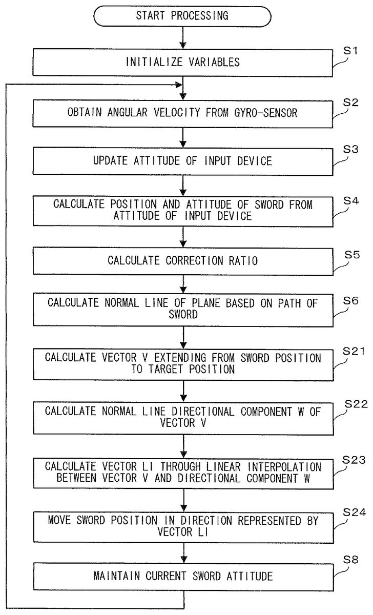
Next, processing according to the second embodiment will be described with reference toFIG. 17andFIG. 18.FIG. 17is a flow chart showing in detail sword movement processing according to the second embodiment, andFIG. 18is a diagram conceptually illustrating the processing of the present embodiment. InFIG. 17, processes from step S1to step S6and a process in step S8are the same as those in step S1to step S6and that in step S8described with reference toFIG. 15in the first embodiment. Thus, detailed description thereof will be omitted.
InFIG. 17, upon completion of calculation of the normal vector nrm in step S6, then in step S21, a vector V extending from the position of the sword object102to the position of the target105is calculated by using the following formula:
V=Tpos−Spas.
Next, in step S22, of the components of the vector V, a directional component W of the normal vector nrm as shown inFIG. 18is calculated by using the following formula:
d=(nrm.x)·(V.x)+(nrm.y)·(V.y)+(nrm.z)·(V.z)
W=nrm·d,
where d is the length of the normal vector nrm component described in the first embodiment.
Next, in step S23, a vector LI is obtained through linear interpolation between the vector V and the directional component W, by using the following formula:
LI=W·k+V·(1−k),
where the coefficient k is an adjustment coefficient ranging from 0.0 to 1.0. Then, the coefficient k is set to represent a difficulty level as described above. In an exemplary case of ten difficulty levels provided as described above, when the difficulty level 1 (easiest) is set, 0 is assigned to the coefficient k. This results in LI=V, and thus a vector toward the target105is calculated. Meanwhile, when the difficulty level 10 (the most difficult) is set, 1 is assigned to the coefficient k. This results in LI=W, and thus the vector LI, a vector only in the direction of the normal vector nrm as described in the first embodiment, is calculated. Furthermore, for the difficulty levels 1 to 10, the coefficients k are assigned such that the difference between any two successive coefficients k is, for example, 0.1.
Next, in step S24, the sword position Spos is corrected in the direction represented by the vector LI. Here, as in the first embodiment, the magnitude of correction to be performed is determined in accordance with the correction ratio. Specifically, the Spos is calculated by using the following formula:
Spos=Spos+LI·ratio.
Subsequently, processes of step S8and thereafter as described in the first embodiment are performed. This is the end of the sword movement processing according to the second embodiment.
As described above, according to the second embodiment, a slight change of the direction of the correction can be realized in accordance with the setting of the difficulty level of the game. In the example above, in a case where the difficulty level is set at 10, the position of the sword object102is corrected only in the direction of the normal vector nrm. However, in a case where the difficulty level is set at 1, correction is performed such that the position of the sword object102is brought toward a direction slightly shifted from the nrm direction toward the target105, whereby a difficulty level of the game can be lowered. Thus, the entertaining feature of the game can be enhanced.
Note that, the gyro-sensor unit7is used in the examples in the embodiments described above. However, the correction ratio, for example, may be calculated based on the acceleration detected by the acceleration sensor37. In such a case, the correction ratio may be in proportional to the magnitude of the detected acceleration.
Moreover, in the embodiments described above, correction processing is always performed irrespective of the magnitude of the motion of the input device8. However, the correction described above may be performed only when the magnitude of the motion of the input device8is larger than a predetermined value. For example, whether or not the magnitude of the angular velocity obtained at step S2is larger than a predetermined value is determined first. Then, only when the magnitude of the angular velocity is larger than the predetermined value, processes of step S3and thereafter may be performed. The magnitude of the motion of the input device8may be determined based on the attitude of the input device calculated at step S3instead of the magnitude of angular velocity. In other words, a difference between the current attitude of the input device8calculated at step S3and the attitude of the input device8calculated in the immediately preceding frame may be calculated to determine whether or not the difference is greater than a predetermined value, so as to determine whether or not the magnitude of the motion of the input device is larger than a predetermined value. Accordingly, correction can be avoided when an amount of the motion of the input device8is small, which further prevents the player from noticing the correction being performed.
With regard to the detection of the attitude of the input device8, detection performed by using the gyro-sensor unit7is used as an example in the embodiments described above. However, the present invention is not limited thereto. For calculation of the attitude of the input device8, an image of the input device8may be taken by using a predetermined camera such that the attitude of the input device8is calculated based on the data of the taken image. For example, an image of the input device8is taken using a predetermined camera, and then the game apparatus3acquires data of the taken image. Then, the CPU10may execute operations of identifying the input device8in the taken image so as to calculate the attitude of the input device8and the moving direction thereof. Thus, based on the calculated moving direction, a direction perpendicular to the moving direction as described above may be calculated.
While the invention has been described in detail, the foregoing description is in all aspects illustrative and not restrictive. It is understood that numerous other modifications and variations can be devised without departing from the scope of the invention.
Claims
- A non-transitory computer-readable storage medium storing an information processing program comprising instructions to be executed by a computer of an information processing apparatus for performing information processing causing an object in a virtual three-dimensional (3D) space to move, based on detected attitude information obtained from an attitude detector configured to detect a 3D attitude of an input device while a user moves the input device, the information processing program causing the computer to perform at least: updating, based on the detected 3D attitude of the input device, a 3D attitude of the object in the virtual 3D space from a previous 3D attitude of the object in the 3D virtual space to an updated 3D attitude of the object in the 3D virtual space;calculating a moving path in the 3D virtual space for the 3D object based on a difference between the previous 3D attitude of the object in the 3D virtual space and the updated 3D attitude of the object in the 3D virtual space;and causing the object to move to a 3D position in the virtual space which is obtained by hypothetically moving the object along the moving path in the 3D virtual space calculated based on the difference between the previous 3D attitude of the object in the 3D virtual space and the updated 3D attitude of the object in the 3D virtual space and then by correcting the 3D position in the virtual space to which the object is hypothetically moved, only in a direction normal or substantially normal to a plane defined in 3D virtual space to contain the moving path in the 3D virtual space calculated based on the difference between the previous 3D attitude of the object in the 3D virtual space and the updated 3D attitude of the object in the 3D virtual space, thereby applying the correction only in a direction other than the moving path.
- The computer-readable storage medium storing the information processing program according to claim 1 , wherein the attitude detector comprises a gyrosensor included in the input device.
- The computer-readable storage medium storing the information processing program according to claim 1 , wherein the object moving causes the object to move such that the object is brought to or brought close to a predetermined targeted position.
- The computer-readable storage medium storing an information processing program according to claim 1 , wherein the information processing program further causes the computer to repeatedly calculate, based on the attitude information, a sequence of input attitudes representing the changing attitude of the input device, and the object moving causes the object to move to a position which is obtained by correcting the position of the object hypothetically moved, only in a direction normal or substantially normal to a plane defined based on the moving path, the direction being defined based on the sequence of input attitudes repeatedly calculated by the input attitude calculation.
- The computer-readable storage medium storing an information processing program according to claim 4 , wherein the plane is defined based on a change of the input attitudes repeatedly calculated by the input attitude calculation.
- The computer-readable storage medium storing an information processing program according to claim 4 , wherein the object moving causes the object to move to a position which is obtained by correcting the position of the object hypothetically moved, only in a direction defined by a vector product of vectors of two predetermined input attitudes among the input attitudes repeatedly calculated by the input attitude calculation.
- The computer-readable storage medium storing an information processing program according to claim 6 , wherein the two predetermined input attitudes among the input attitudes repeatedly calculated by the input attitude calculation are input attitudes calculated in succession.
- The computer-readable storage medium storing an information processing program according to claim 1 , wherein the information processing program further causes the computer to determine whether or not a magnitude of a motion of the input device is larger than a predetermined value, and the object moving performs correction when the motion determination determines that the magnitude of the motion of the input device is larger than the predetermined value.
- The computer-readable storage medium storing an information processing program according to claim 8 , wherein the object moving calculates correction direction data representing a direction normal or substantially normal to a plane defined based on the moving path, and increases a magnitude of the correction to be performed in a direction represented by the correction direction data in accordance with an increase in the magnitude of the motion of the input device.
- The computer-readable storage medium storing an information processing program according to claim 1 , wherein the object moving calculates correction direction data representing a direction normal or substantially normal to a plane defined based on the moving path, and increases a magnitude of correction to be performed in a direction represented by the correction direction data in accordance with an increase in the magnitude of the motion of the input device.
- The computer-readable storage medium storing an information processing program according to claim 1 , wherein the object moving calculates correction direction data and then by correcting the position of the object hypothetically moved, only in the direction represented by the correction direction data.
- The computer-readable storage medium storing an information processing program according to claim 1 , wherein the attitude detector includes an angular velocity sensor, and the motion information includes information containing an angular velocity detected by the angular velocity sensor.
- The storage medium of claim 1 wherein the attitude detector comprises a gyrosensor that detects angular rate of change of input device attitude.
- The storage medium of claim 1 wherein attitude Gdir is represented in three dimensions by [ Gdir . X . x Gdir . X . y Gdir . X . z Gdir . Y . x Gdir . Y . y Gdir . Y . z Gdir . Z . x Gdir . Z . y Gdir . Z . z ] .
- An information processing apparatus for performing information processing for causing an object in a virtual three-dimensional (3D) space to move, based on detected attitude obtained from predetermined detection for detecting a previous 3D attitude and an updated 3D attitude of an input device operated by a user, comprising: a 3D attitude updater that updates, based on the detected 3D attitude of the input device, a 3D attitude of the object in the virtual 3D space from a previous 3D attitude of the object in the 3D virtual space to an updated 3D attitude of the object in the 3D virtual space;a 3D moving direction calculator structured to calculate, based on a difference between the previous 3D attitude of the input device and the updated 3D attitude of the input device, a 3D moving direction representing a 3D moving path of the object in the virtual space;and an object mover structured to cause the object to move to a 3D position in virtual space which is obtained by hypothetically moving the object along the 3D moving path in the virtual space calculated based on the difference between the previous 3D attitude of the object in the 3D virtual space and the updated 3D attitude of the object in the 3D virtual space and then by correcting the 3D position in the virtual space to which the object is hypothetically moved, only in a direction normal or substantially normal to a plane defined in 3D virtual space to contain the moving path in the 3D virtual space calculated based on the difference between the previous 3D attitude of the object in the 3D virtual space and the updated 3D attitude of the object in the 3D virtual space, thereby applying the correction only in a direction other than the moving path.
- A method for causing an object in a virtual three-dimensional (3D) space to move, based on attitude information obtained from predetermined detection for detecting 3D attitudes of an input device operated by a user, comprising: detecting plural 3D attitudes of the input device;updating, based on the detected 3D attitudes of the input device, a 3D attitude of the object in the 3D virtual space from a previous 3D attitude of the object in the 3D virtual space to an updated 3D attitude of the object in the 3D virtual space;calculating, based on changes between the detected plural attitudes of the input device including a difference between the previous 3D attitude of the object in the 3D virtual space and the updated 3D attitude of the object in the 3D virtual space, a 3D moving path in the 3D virtual space for the object to move in the 3D virtual space;and causing the object to move to a 3D position in the virtual space which is obtained by hypothetically moving the object along the 3D moving path calculated based on the difference between the previous 3D attitude of the object in the 3D virtual space and the updated 3D attitude of the object in the 3D virtual space and then by correcting the 3D position in the virtual space to which the object is hypothetically moved, only in a direction normal or substantially normal to a plane defined in 3D virtual space to contain the 3D moving path in the 3D virtual space calculated based on the difference between the previous 3D attitude of the object in the 3D virtual space and the updated 3D attitude of the object in the 3D virtual space, thereby applying the correction only in a direction other than the calculated 3D moving path.
- A system for causing an object in a virtual three-dimensional (3D) space to move, comprising: an input device operated by a user, the input device comprising a gyrosensor that senses the attitudes of the input device while the user moves the input device;and a processor operatively coupled to the input device that causes an object in a virtual 3D space to move based on changes in the sensed attitudes of the input device, the processor: updating, based on the sensed attitudes of the input device, a 3D attitude of the object in the 3D virtual space from a previous 3D attitude of the object in the 3D virtual space to an updated 3D attitude of the object in the 3D virtual space;calculating, based on the sensed attitude changes including a difference between the previous 3D attitude of the object in the 3D virtual space and the updated 3D attitude of the object in the 3D virtual space, a 3D moving path;and causing the object to move to a 3D position in the virtual space which is obtained by hypothetically moving the object along the 3D moving path in the 3D virtual space calculated based on the difference between the previous 3D attitude of the object in the 3D virtual space and the updated 3D attitude of the object in the 3D virtual space and then by correcting the 3D position in the virtual space to which the object is hypothetically moved, only in a direction normal or substantially normal to a plane defined in 3D space to contain the 3D moving path in the 3D virtual space calculated based on the difference between the previous 3D attitude of the object in the 3D virtual space and the updated 3D attitude of the object in the 3D virtual space, thereby applying the correction of the object only in a direction other than the 3D moving path.
Disclaimer: Data collected from the USPTO and may be malformed, incomplete, and/or otherwise inaccurate.