Illustrative Figure
Abstract
A game controller for controlling video games or other electronic interactive systems, having an adjustable trigger system for calibration or customized control of trigger action. The game controller includes a controller chassis and an actuator system, which includes a trigger body, a trigger mechanism chassis, a strike plate coupled to the trigger body, a first trigger adjustment control screw received in a screw thread disposed within the controller chassis, and a second trigger adjustment control screw received in a screw thread disposed within the controller chassis, wherein a portion of each of the first trigger adjustment control screw and second trigger adjustment control screw engages with a respective portion of the strike plate, and said portion of each of the first trigger adjustment control screw and second trigger adjustment control screw each create an end stop to limit the actuator movement of the trigger body.
Description
DETAILED DESCRIPTION OF THE INVENTION Detailed descriptions of specific embodiments of the game controller and its trigger mechanisms are disclosed herein. It will be understood that the disclosed embodiments are merely examples of the way in which certain aspects of the invention can be implemented and do not represent an exhaustive list of all of the ways the invention may be embodied. Indeed, it will be understood that the game controller and its trigger mechanisms described herein may be embodied in various and alternative forms. The figures are not necessarily to scale and some features may be exaggerated or minimised to show details of particular components. Well-known components, materials or methods are not necessarily described in great detail in order to avoid obscuring the present disclosure. Any specific structural and functional details disclosed herein are not to be interpreted as limiting, but merely as a basis for the claims and as a representative basis for teaching one skilled in the art to variously employ the invention. FIG. 1is exemplary of a game controller100in which the present invention could be employed. The game controller100includes a bumper control function102, button control functions104, analogue joystick controls106, and a trigger body108.FIG. 1illustrates the positions of the trigger body108in relation to the position of the aforementioned features of the game controller100. FIG. 2is a cut-away view of part of the game controller100illustrating an adjustable trigger mechanism according to a first embodiment of the invention. The game controller100also includes a controller chassis110, which encloses its internal components. The trigger body108can extend at least partially through an opening in the controller chassis110. Referring now also toFIGS. 3-8, the game controller100also includes: a printed circuit board (PCB)112; a trigger mechanism chassis114fixed to the PCB112; an adjustment strike plate116integral to the trigger body108; a first trigger adjustment control screw118for ...
DETAILED DESCRIPTION OF THE INVENTION
Detailed descriptions of specific embodiments of the game controller and its trigger mechanisms are disclosed herein. It will be understood that the disclosed embodiments are merely examples of the way in which certain aspects of the invention can be implemented and do not represent an exhaustive list of all of the ways the invention may be embodied. Indeed, it will be understood that the game controller and its trigger mechanisms described herein may be embodied in various and alternative forms. The figures are not necessarily to scale and some features may be exaggerated or minimised to show details of particular components. Well-known components, materials or methods are not necessarily described in great detail in order to avoid obscuring the present disclosure. Any specific structural and functional details disclosed herein are not to be interpreted as limiting, but merely as a basis for the claims and as a representative basis for teaching one skilled in the art to variously employ the invention.
FIG. 1is exemplary of a game controller100in which the present invention could be employed. The game controller100includes a bumper control function102, button control functions104, analogue joystick controls106, and a trigger body108.FIG. 1illustrates the positions of the trigger body108in relation to the position of the aforementioned features of the game controller100.
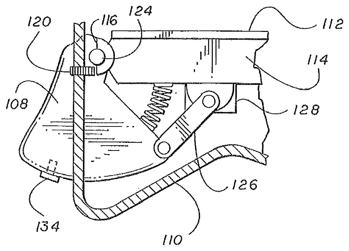
FIG. 2is a cut-away view of part of the game controller100illustrating an adjustable trigger mechanism according to a first embodiment of the invention. The game controller100also includes a controller chassis110, which encloses its internal components. The trigger body108can extend at least partially through an opening in the controller chassis110. Referring now also toFIGS. 3-8, the game controller100also includes:
a printed circuit board (PCB)112;
a trigger mechanism chassis114fixed to the PCB112;
an adjustment strike plate116integral to the trigger body108;
a first trigger adjustment control screw118for adjustment of trigger depression;
a second trigger adjustment control screw120for adjustment of the trigger command initiation point;
a threaded insert or screw thread122cut into the controller chassis110;
a trigger pivot bearing124integrally formed with the trigger mechanism chassis;
a trigger sensor link arm126; and
a trigger motion sensor128.
FIG. 3is an enlarged section ofFIG. 2showing in more detail the trigger adjustment mechanism in accordance with the invention.
FIG. 4is a cross sectional view of the trigger mechanism. In this embodiment the trigger mechanism has two trigger adjustment control screws118,120; first trigger adjustment control screw118for adjustment of trigger depression, and second trigger adjustment control screw120for adjustment of trigger command initiation point as shown inFIG. 2respectively.
In this embodiment the first and second trigger adjustment control screws118and120that are used are grub screws but could be many different threaded mechanisms.
In this embodiment the screw thread122for receiving the screw mechanisms is cut into the chassis110of the game controller100as shown inFIGS. 2 and 3, respectively. In other embodiments, it would be possible to use threaded inserts with nylon locking systems or entire adjustment mechanisms130,132fitted as a complete component that could be inserted through an aperture in the controller chassis110in such embodiment it is envisaged that the user may be able to adjust the trigger settings without the use of a tool, for example by providing a grip coupled to the screw thread, preferably this would be integral with the screw thread as shown inFIGS. 7 and 8.
In some embodiments, the position of the trigger body108would be adjusted by use of a specified tool that would be provided to turn the first and second trigger adjustment control screws118and120, which are located next to the trigger body108, on the controller chassis110.
One advantage of the present invention is that it allows adjustments to be made to the trigger response; such adjustment could be customised to suit the nature of the video game that is in use at the time of operation and the skill of the operator. For example, in combat style games involving a shooting function it is often the case that the trigger would need to be depressed a certain amount before any command was prompted. The second trigger adjustment control screw120can be adjusted so that the command was prompted with any amount of depression of the trigger body108, by using the required tool (for example an Allen key, or hex or star driver, cross head or flat head screwdriver, spanner or wrench) to turn the second trigger adjustment control screw120, whereby driving it into or out of the controller chassis110by virtue of the threaded insert or screw thread located within controller chassis110.
After reaching or passing the command initiation point no further commands are given from the trigger sensor link arm126to the trigger motion sensor128; therefore the first trigger adjustment control screw118which controls the degree of trigger depression allows the operator to restrict the amount of travel available to the trigger body108, as they desire. The first trigger adjustment control screw118would impede the movement by striking the adjustment strike plates, which are preferably formed integrally with the trigger body108, which trigger body108is pivotally mounted preferably on a trigger pivot bearing which may also be integral to trigger mechanism chassis124.
Such an adjustment would directly relate to the majority of combat style games or other varieties of firing operations in video games.
The present invention could find application in a variety of other video games genres but for the simplicity of this disclosure reference is made to combat style games.
A further advantage of the present invention is that it minimises the amount of motion an operators finger must travel, therefore minimising the recovery time after trigger initiation contacts have been made allowing the operator to commence command prompt again and again more rapidly, or to operate different commands quicker. As the movement that is required to operate commands detected by the trigger motion sensor128, by depressing the trigger body108, the risks of any related repetitive strain injury acquired due to the repeated movement of the finger when operating the trigger function would be greatly reduced. In known controllers the operator may be require to move their finger 11 mm whereas in the present invention adjustment of the first trigger adjustment control screw118and the second trigger adjustment control screw120allow the operator to reduce the required movement of their finger to 5 mm thus reducing the overall motion required by the operator by over 50% of the initial movement required, whereby providing a health benefit to users retaining healthy joints after many years of vigorous gaming. Repetitive strain injury is a clinically proven medical issue related to hours of repeated movements made during activities like the movements made while depressing the trigger function of the controller.
In other video game genres, such as driving games, trigger response could be controlled by adjustment of the first trigger adjustment control screw118and the second trigger adjustment control screw120to allow the operator greater control over breaking and accelerating functions of the game, for example restricting maximum throttle settings and breaking level settings for difficult corners. This could be adjusted by assessing where the greatest advantageous breaking or accelerating position would be, and then recreating this position with the trigger adjustment control screw for adjustment of trigger depression118.
In this application the degree of the trigger body108depression is detected by trigger motion sensor128which are coupled together by the trigger sensor link arm126. The degree of depression of the trigger body108is converted into a signal which signal directly relates to a command to be executed by the video game for example the amount of acceleration or braking to be applied. The trigger motion sensor128is connected to the trigger mechanism chassis114coupled to the printed circuit board112. The present invention provides a device to restrict the range of movement of the trigger body108which the trigger motion sensor128is effectively able to detect, and thus limit the magnitude of the command which can be made by the operator when depressing trigger. A further advantage of this embodiment is that the ergonomic design of the controller is not compromised.
FIG. 6depicts the use of a stopping block134for control of trigger depression, this could be achieved by insertion into the base of the trigger of a screw comprising screw head which interacts with controller chassis110. This system could be used instead of the trigger adjustment control screw118for adjustment of trigger depression. This system may incorporate a stopping block of the desired shape and size to prevent the trigger from depressing fully and this would be attached via a screw fixing into a threaded portion of the trigger body108, or by any other means of mechanical fixing such as those that would be apparent to those skilled in the art. The stopping block134could be interchangeable with stopping blocks or different dimensions depending on the intended application and the degree to which movement of the trigger is to be restricted. The screw head itself may be shaped such that the angular orientation of the screw with respect to the controller chassis110determines the degree of trigger movement, for example the outer surface of the screw head could be any noncircular shape such as oval or spiral shape, wherein the radial dimension of the screw head is not constant. In such embodiment is envisaged that trigger adjustment control screw120may also be employed in order to provide adjustment of trigger command initiation point to achieve fully adjustable trigger commands.
It can be appreciated that various changes may be made within the scope of the various embodiments of present invention, for example, the size and shape of the features may be adjusted. In other embodiments of the invention it is envisaged that a system could incorporate several button or slider controls on the external case of the controller which may be adjusted to select pre-set ranges of movement, or pre-set trigger depression or preset trigger initiation command points. Each of these could be pre-set in manufacture or by the operator to correspond to popular video games or specifically chosen video games that the operator has chosen for maximum efficiency. It is also envisaged this invention could be used for other buttons provided on the controller. It is envisaged the invention could be employed with digital sensors or switches which generate digital signals having an on state and an off state since such switches typically require a predetermined range of movement to change states such that required range of movement to change states can be reduced. It is also envisaged this invention could be incorporated to adjust the button depression depth required of such digital switches to its greatest point before such a command for the function it controls would be given.
In some embodiments the first trigger adjustment control screws118and the second trigger adjustment control screw120can be entirely released restoring the full range of trigger movement.
It will be recognised that as used herein, directional references such as “top”, “bottom”, “front”, “back”, “end”, “side”, “inner”, “outer”, “upper” and “lower” do not limit the respective features to such orientation, but merely serve to distinguish these features from one another.
While particular embodiments of the invention have been shown and described, numerous variations and alternate embodiments will occur to those skilled in the art without departing from the scope of the present invention.
Claims
- A game controller configured to supply input to a computer program, comprising: a controller chassis comprising a first outer wall, wherein the first outer wall includes an outer surface of the game controller;an actuator body that extends at least partially through an opening in the first outer wall, wherein the actuator body is configured to move relative to the controller chassis;and a stopping block, wherein the stopping block includes a screw and the actuator body includes a screw thread, wherein the screw thread is configured to receive the screw of the stopping block;wherein the stopping block is configured to contact the outer surface of the first outer wall the at a stop position of the actuator body;and wherein the stop position defines one end of a range of motion of the actuator body.
- The game controller of claim 1 , wherein the stop position is a point of maximum depression of the actuator body.
- The game controller of claim 1 , wherein the actuator body is pivotably mounted to the controller chassis.
- The game controller of claim 1 , further comprising means for biasing the actuator body away from or out of the controller chassis.
- The game controller of claim 1 , wherein the stopping block is configured to contact the controller chassis to stop movement of the actuator body towards or into the controller chassis.
- The game controller of claim 1 , wherein the stopping block and the actuator body are configured to be adjustably coupled to one another by the screw that is configured to be received in the screw thread.
- The game controller of claim 1 , wherein the actuator body includes a plurality of screw threads and each of the screw threads is configured to receive the screw of the stopping blocks.
- The game controller of claim 1 , wherein the stopping block is configured such that an angular orientation of the screw in the screw thread determines the stop position of the actuator body.
- The game controller of claim 1 , comprising a plurality of stopping blocks, wherein dimensions of the stopping blocks are different from one another.
- The game controller of claim 1 , wherein the actuator body includes a trigger button.
- The game controller of claim 1 , wherein the stopping block is a screw head.
- The game controller of claim 11 , wherein the screw head has a non-uniform radius.
- The game controller of claim 1 , wherein the stopping block has one of an oval shape and a spiral shape.
- The game controller of claim 1 , wherein the actuator body is configured to be depressed into the controller chassis through the opening in the first outer wall.
- The game controller of claim 1 , wherein the stopping block is attached to the actuator body adjacent a first surface of the actuator body, wherein the first surface of the actuator body is adjacent a first edge of the opening.
- The game controller of claim 1 , wherein the stopping block is attached to the actuator body at a position that is between a surface of the actuator body that is configured to be contacted to depress the actuator body and the outer surface of the first outer wall.
Disclaimer: Data collected from the USPTO and may be malformed, incomplete, and/or otherwise inaccurate.