U.S. Pat. No. 9,283,482
GAME APPARATUS FOR PERFORMING GAME PROCESSING ACCORDING TO AN ATTITUDE OF AN INPUT DEVICE AND GAME PROGRAM
AssigneeNINTENDO CO., LTD.
Issue DateSeptember 4, 2014
Illustrative Figure
Abstract
A game apparatus includes a CPU, and the CPU sets a moving direction, that is, a position and an orientation of a moving object within a game space on the basis of angular velocity data transmitted from a first controller, that is, an attitude of a gyro sensor unit (gyro sensor). Then, when a second controller is drawn toward a near side in a state that a C button and a Z button thereof are simultaneously pressed, and the C button and the Z button are simultaneously released in that state, the moving object is shot.
Description
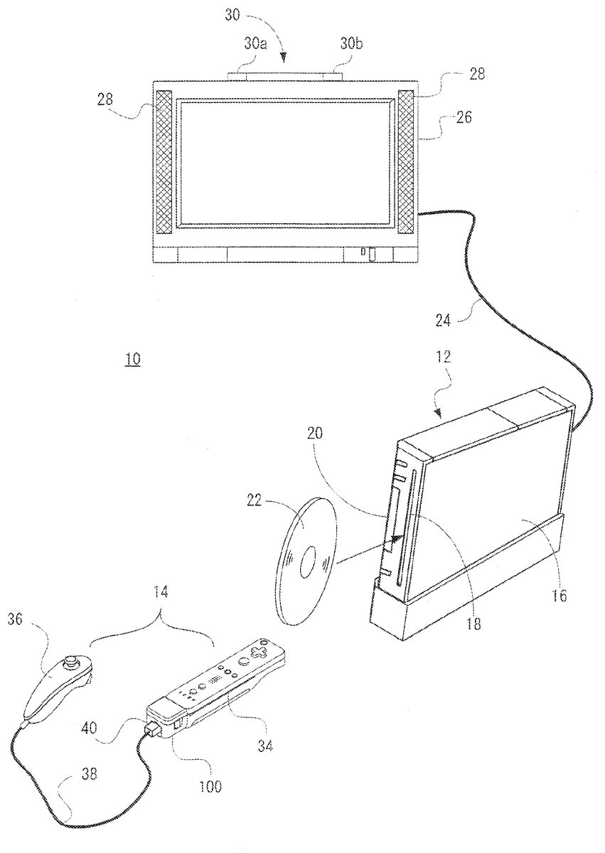
DETAILED DESCRIPTION OF THE PREFERRED EMBODIMENTS Referring toFIG. 1, a game system10of one embodiment includes a video game apparatus (hereinafter, referred to as “game apparatus”)12and a controller14. The controller14functions as an input device or an operating device by a user or a player. The game apparatus12and the controller14are connected by radio. For example, the wireless communication is executed according to a Bluetooth (registered trademark) standard, but may be executed according to other standards, such as an infrared ray communication, a wireless LAN, etc. The game apparatus12includes a roughly rectangular parallelepiped housing16, and the housing16is furnished with a disk slot18and an external memory card slot cover20on a front surface. An optical disk22as one example of an information storage medium storing game program and data, etc. is inserted from the disk slot18to be loaded into a disk drive74(seeFIG. 10) within the housing16. Inside the external memory card slot cover20is provided a connector for external memory card48(FIG. 10) through which a memory card (not shown) is inserted. The memory card is employed for loading the game program, etc. read from the optical disk22to temporarily store it, storing (saving) game data (result data or proceeding data of the game) of the game played by means of the game system10, and so forth. It should be noted that storing the game data described above may be performed on an internal memory such as a flash memory64(FIG. 10) in place of the external memory card. The game apparatus12has an AV cable connector (not illustrated) on a rear surface of the housing16, and by means of the connector, the game apparatus12is connected to a monitor (display)26via an AV cable24. The monitor26is typically a color television receiver, and through the AV cable24, a video signal from the game apparatus12is input to a video input terminal of the color ...
DETAILED DESCRIPTION OF THE PREFERRED EMBODIMENTS
Referring toFIG. 1, a game system10of one embodiment includes a video game apparatus (hereinafter, referred to as “game apparatus”)12and a controller14. The controller14functions as an input device or an operating device by a user or a player. The game apparatus12and the controller14are connected by radio. For example, the wireless communication is executed according to a Bluetooth (registered trademark) standard, but may be executed according to other standards, such as an infrared ray communication, a wireless LAN, etc.
The game apparatus12includes a roughly rectangular parallelepiped housing16, and the housing16is furnished with a disk slot18and an external memory card slot cover20on a front surface. An optical disk22as one example of an information storage medium storing game program and data, etc. is inserted from the disk slot18to be loaded into a disk drive74(seeFIG. 10) within the housing16. Inside the external memory card slot cover20is provided a connector for external memory card48(FIG. 10) through which a memory card (not shown) is inserted. The memory card is employed for loading the game program, etc. read from the optical disk22to temporarily store it, storing (saving) game data (result data or proceeding data of the game) of the game played by means of the game system10, and so forth. It should be noted that storing the game data described above may be performed on an internal memory such as a flash memory64(FIG. 10) in place of the external memory card.
The game apparatus12has an AV cable connector (not illustrated) on a rear surface of the housing16, and by means of the connector, the game apparatus12is connected to a monitor (display)26via an AV cable24. The monitor26is typically a color television receiver, and through the AV cable24, a video signal from the game apparatus12is input to a video input terminal of the color television, and a sound signal is input to a sound input terminal thereof. Accordingly, a game image of a three-dimensional (3D) video game, for example, is displayed on the screen of the color television (monitor)26, and a stereo game sound, such as a game music, a sound effect is output from integrated speakers28.
Additionally, around the monitor26(upper side of the monitor26in this embodiment), a marker unit30having two infrared ray LEDs (markers)30aand30bis provided. The marker unit30is connected to the game apparatus12through a power source cable (not shown). Accordingly, the marker unit30is supplied with power from the game apparatus12. The markers30aand30bemit and output infrared rays forward the monitor26.
Furthermore, the power of the game apparatus12is applied by means of a general AC adapter (not illustrated). The AC adapter is connected to a standard wall outlet for home use, and transforms the house current to a low DC voltage signal suitable for driving the game apparatus12. In another embodiment, a battery may be utilized as a power supply.
The controller14, which is described in detail later, includes a first controller34and a second controller36each capable of being held with one hand and a gyro sensor unit100detachably attached to the first controller34. On a rear end surface of the first controller34, a connector42(FIG. 2(A),FIG. 11) is provided, and at an end of a cable38extending from the rear end of the second controller36, a connector40(FIG. 1,FIG. 5,FIG. 11) is provided, and on a front end surface and a rear end surface of the gyro sensor unit100, connectors106and108(FIG. 6(A),FIG. 6(B),FIG. 7andFIG. 11) are respectively provided. The connector106at the front end surface of the gyro sensor unit100is connectable to the connector42of the first controller34, and the connector40of the second controller36is connectable to the connector42of the first controller34or the connector108at the rear end surface of the gyro sensor unit100.
By connecting the connector106to the connector42, the gyro sensor unit100is physically and electrically connected to the first controller34. From the gyro sensor unit100thus attached (connected as a single unit) to the first controller34, angular velocity data indicating an angular velocity of the first controller34is output.
In a case that the gyro sensor unit100is thus attached to the first controller34, the connector40of the second controller36is connected to the connector108at the rear end surface of the gyro sensor unit100. That is, the connector42has a structure selectively connectable to either of the connector106or the connector40, and the connector40has a structure of selectively connectable to either of the connector42or the connector108. Accordingly, the connector106and the connector108provided to the gyro sensor unit100cannot actually be connected because of being a part of the same housing, but have shapes connectable with each other. Input data from the second controller36is applied to the first controller34via the cable38and the gyro sensor unit100. The first controller34transmits controller data including input data from the first controller34itself, angular velocity data from the gyro sensor unit100, and input data from the second controller36to the game apparatus12.
Alternatively, in a case that the connector40is connected to the connector42, operation data or input data from the second controller36are applied to the first controller34via the cable38, and the first controller34transmits controller data including the input data from the first controller34itself and the input data from the second controller36to the game apparatus12.
In the system here for transmitting the input data from the first controller34and the input data from the second controller36, a data amount to be transmitted at a time may sometimes be designed so as not be added, but in a case that the gyro unit100is added, angular velocity data from the gyro unit100and input data from the second controller36are alternately output to the first controller36, which allows both of the data to be transmitted. The data control can be performed by the gyro unit100, so that the first controller34and the second controller36are not required to be changed in design.
Thus, the first controller34inputs by radio to the game apparatus12an operation signal and operation data (data) from the second controller36and the gyro sensor unit100as well as the operation signal and the operation data (data) from the controller34away from the game apparatus12, and therefore, the first controller34may sometimes be called a “remote controller”. Furthermore, the second controller36is called “Nunchaku” for the sake of its shape, and therefore, it may sometimes be called so.
Thus, the gyro sensor unit100is an expanding unit for adding a gyro function to the first controller34by utilizing the existing first controller34and second controller36as it is.
In the game system10, a user first turns the power of the game apparatus12on for playing the game (or another application), then selects an appropriate optical disk22storing a video game (or another application the player wants to play), and loads the optical disk22into the disk drive74through the disk slot18of the game apparatus12. In response thereto, the game apparatus12starts to execute a video game or another application on the basis of the software stored in the optical disk22. The user operates the controller14in order to apply an input to the game apparatus12.
FIGS. 2(A) and 2(B)show one example of an appearance of the remote controller or the first controller34.FIG. 2(A)is a perspective view of the first controller34as seeing it from above rear, andFIG. 2(B)is a perspective view of the first controller34as seeing it from below front.
The first controller34has a housing44formed by plastic molding, for example. The housing44is formed into an approximately rectangular parallelepiped shape regarding a back and forth direction (Z-axis direction shown) as a longitudinal direction, and has a size small enough to be held by one hand of a child and an adult. As one example, the housing44has a length or a width approximately the same as that of a palm of a person. The player can perform a game operation by means of the first controller34, that is, by pushing the buttons provided on it and by changing a position and a direction of the first controller34itself.
The housing44is provided with a plurality of operation buttons. That is, on the top surface of the housing44, a cross key46a, an 1 button46b, a 2 button46c, an A button46d, a −(minus) button46e, a home (HOME) button46f, and a +(plus) button or start button46gare provided. Meanwhile, on the bottom surface of the housing44, a concave portion is formed, and on the reward inclined surface of the concave portion, a B button46his provided. Each of the buttons (switches)46a-46his assigned an appropriate function depending on a game program to be executed by the game apparatus12. Furthermore, the housing44has a power switch46ifor turning on and off the power of the main body of the game apparatus12from a remote place on a top surface. The respective buttons (switches) provided on the first controller34may inclusively be indicated as an operating means or an input means with the use of the reference numeral46.
The cross key46ais a four directional push switch, including four directions of front (or upper), back (or lower), right and left operation parts. By operating any one of the operation parts, it is possible to instruct a moving direction of a character or an object (player character or player object) that is operable by a player, instruct the moving direction of a cursor, or merely instruct a direction.
The 1 button46band the 2 button46care respectively push button switches, and are used for a game operation, such as adjusting a viewpoint position and a viewpoint direction on displaying the 3D game image, i.e. a position and an image angle of a virtual camera. Alternatively, the 1 button46band the 2 button46ccan be used for the same operation as that of the A-button46dand the B button46hor an auxiliary operation.
The A-button switch46dis the push button switch, and is used for causing the player character or the player object to take an action other than a directional instruction, specifically arbitrary actions such as hitting (punching), throwing, grasping (acquiring), riding, and jumping, etc. For example, in an action game, it is possible to give an instruction to jump, punch, move a weapon, and so forth. Also, in a roll playing game (RPG) and a simulation RPG, it is possible to instruct to acquire an item, select and determine the weapon and command, and so forth. Furthermore, in a case that the controller34is used as a pointing device, the A-button switch46dis used to instruct a decision of an icon or a button image instructed by a pointer (instruction image) on the game screen. For example, when the icon or the button image is decided, an instruction or a command set in advance corresponding thereto can be input.
The − button46e, the HOME button46f, the + button46g, and the power supply switch46iare also push button switches. The − button46eis used for selecting a game mode. The HOME button46fis used for displaying a game menu (menu screen). The + button46gis used for starting (resuming) or pausing the game. The power supply switch46iis used for turning on/off a power supply of the game apparatus12by remote control. It should be noted that in this embodiment, a power switch for turning on and off the controller34itself is not furnished, and the controller34is turned on in response to any of the operating means and the input means46of the controller34being operated, and automatically turned off in response to no operation for a constant period (30 seconds, for example) and more.
The B button46his also the push button switch, and is mainly used for inputting a trigger such as shooting, and designating a position selected by the controller34. In a case that the B button46his continued to be pushed, it is possible to make movements and parameters of the player object constant. In a fixed case, the B button46hfunctions in the same way as a normal B-button, and is used for canceling an action and a command determined by the A-button46d.
Within the housing44, an acceleration sensor84(FIG. 11) for detecting accelerations in three-axis directions of X, Y and Z (that is, right and left direction, up and down direction and forward and reward direction) shown inFIG. 2is provided. Alternatively, as an acceleration sensor84, a two-axis acceleration sensor for detecting accelerations in any two directions out of the right and left direction, up and down direction and forward and reward direction may be used depending on the restriction on a shape of the housing44, a way of holding the first controller34, or the like. Under certain circumstances, a one-axis acceleration sensor may be used.
On the front surface of the housing44, a light incident opening44bis formed, and inside the housing44, an imaged information arithmetic section50is further provided. The imaged information arithmetic section50is made up of a camera for imaging infrared rays and an arithmetic operation portion for calculating coordinates of imaged objects within an image, and captures an object scene including the above-described markers30aand30bby the infrared rays to calculate position coordinates of the markers30aand30bwithin the object scene.
On the rear surface of the housing44, the above-described connector42is provided. The connector42is utilized for connecting other equipment to the first controller34. In this embodiment, the connector42is connected with the connector40of the second controller36or the connector106of the gyro sensor unit100.
Moreover, on the rear surface of the housing44, a pair of through holes48aand48bis formed in such positions as to be symmetrically with each other (X-axis direction) about the connector42. The pair of through holes48aand48bis for being inserted with hooks112Fa and112Fb (FIG. 6(A)) to securing the gyro sensor unit100at the rear surface of the housing44. At the rear surface of the housing44, a through hole48cfor attaching a strap56(FIG. 5) is also provided.
FIGS. 3(A) and 3(B)are an illustrative view showing one example of an appearance of the Nunchaku or the second controller36itself.FIG. 3(A)is a perspective view of the second controller36as seeing it from above rear, andFIG. 3(B)is a perspective view of the second controller36as seeing it from below front. InFIG. 3(B), the cable38of the second controller36is omitted.
The second controller36has a housing52formed by plastic molding, for example. The housing52is formed into an approximately thin long elliptical shape in the forward and backward direction (Z-axis direction) when viewed from plane, and the width of the right and left direction (X-axis direction) at the rear end is narrower than that of the front end. Furthermore, the housing52has a curved shape as a whole when viewed from a side, and downwardly curved from a horizontal portion at the front end to the rear end. The housing52has a size small enough to be held by one hand of a child and an adult similar to the first controller34as a whole, and has a longitudinal length (in the Z-axis direction) slightly shorter than that of the housing44of the first controller34. Even with the second controller36, the player can perform a game operation by operating buttons and a stick, and by changing a position and a direction of the controller itself.
At the front end of the top surface of the housing52, an analog joystick54ais provided. At the end of the housing52, a front edge slightly inclined backward is provided, and on the front edge, a C button54band a Z button54care vertically (Y-axis direction inFIG. 3) provided. The analog joystick54aand the respective buttons54band54care assigned appropriate functions according to a game program to be executed by the game apparatus12. The analog joystick54aand the respective buttons54band54cprovided to the second controller36may be inclusively denoted by means of the reference numeral88.
Inside the housing52of the second controller36, an acceleration sensor86(FIG. 11) is provided. As the acceleration sensor86, an acceleration sensor similar to the acceleration sensor84in the first controller34is applied. More specifically, a three-axis acceleration sensor is applied in this embodiment, and detects accelerations in each of the three axis directions such as an up and down direction (Y-axial direction shown), a right and left direction (X-axial direction shown), and a forward and backward direction (Z-axial direction shown) of the second controller36. Accordingly, similar to the case of the first controller34, proper arithmetic process is performed on the detected accelerations to thereby calculate a tilt and a rotation of the second controller36and an attitude of the acceleration sensor86in the direction of gravity. Furthermore, it is possible to calculate a motion applied to the first controller34by swinging, etc. as with the case of the second controller36.
FIG. 4shows one example of an appearance of the connector40of the second controller36.FIG. 4is a perspective view of the connector40as seeing it from below front. Here also, the cable38is omitted. The connector40has a housing122formed by a plastics molding, for example. At the bottom surface of the housing122, a hook124is provided. The hook124is for intrinsically hanging and retaining a cord of the strap56attached to the first controller34when the connector40is directly connected to the first controller34(or the connector42) as shown inFIG. 5. By hanging and retaining the cord of the strap56on the hook144, it is possible to tightly secure the first controller34and the second controller36.
FIGS. 6(A) and 6(B)show one example of an appearance of the gyro sensor unit100.FIG. 6(A)is a perspective view of the gyro sensor unit100as seeing it from above front, andFIG. 6(B)is a perspective view of the gyro sensor unit100as seeing it from rear back.
The gyro sensor unit100has a housing110formed by a plastics molding, for example. The housing110has an appropriately rectangular parallelepiped shape, and the length is ⅕ of the length of the housing44of the first controller34, and the width and thickness are approximately the same as those of the housing44. The player can play a game operation by changing a position and a direction of the first controller34itself even if the first controller34is attached with the gyro sensor unit100.
On the front surface and the rear surface of the housing110, the above-described connectors106and108are respectively provided, on the side surfaces of the housing110, a pair of release buttons112aand112bare provided, and the bottom surface of the housing110, a lock switch114is provided. An approximately sphere concave portion110ais provided from the end of the front surface of the housing110to the bottom surface such that the through hole48cfor the strap56is exposed in a state that the first controller34is attached with the gyro sensor unit100(FIG. 8).
The pair of release buttons112aand112b, and a pair of hooks112Fa and112Fb which are respectively associated with the release buttons112aand112bare provided on a front surface of the housing110at positions symmetrically with each other in a horizontal direction (X-axis direction) about the connector106. When the connector106is connected to the connector42in order to attach the gyro sensor unit100to the first controller34, the pair of hooks112Fa and112Fb is inserted to the pair of through holes48aand48b(FIG. 2(A)) at the rear surface of the housing44, and the pawls of the hooks112Fa and112Fb are engaged with the inner wall of the housing44. Thus, the gyro sensor unit100is fixed to the rear surface of the first controller34.
FIG. 8shows the gyro sensor unit100thus attached to the first controller34. When the pair of release buttons112aand112bare pushed in this state, the engagement of the pawls are released to allow the gyro sensor unit100to be detached from the first controller34.
A lock switch114is a sliding switch for locking such the release buttons112aand112b. The release buttons112aand112bcannot be pushed (locked state) when the lock switch114is in a first position (toward the rear side, for example), and the release buttons112aand112bcan be pushed (released state) when the lock switch114is in a second position (toward the front, for example). Within the housing110, locking springs118aand118b(FIG. 7) are provided and constructed so as to be repulsed when the release button112aand112bare pushed, and so as to maintain the engaged state when the release button112aand112bare not pushed. Thus, in order to remove the gyro sensor unit100, the user has to push the release buttons112aand112bafter sliding the lock switch114from the first position to the second position.
Since the gyro sensor unit100is attached to the rear surface of the first controller34, a centrifugal force applied to the gyro sensor unit100during the game is exclusively worked such that the gyro sensor unit100is pressed against the first controller34. Furthermore, the gyro sensor unit100is fixed to the rear surface of the first controller34by the hooks112Fa and112Fb while the lock switch114for releasing the hooks112Fa and112Fb is provided to the release buttons112aand112b, and therefore, even during operating the game, it is possible to bring about a tightly secured state between the gyro sensor unit100and the first controller34.
On the rear surface of the housing110, a concave portion110bcapable of housing the connector cover116to be attached to the connector108is provided on the periphery of the connector108. The connector cover116has a narrow thin (that is, can be bended) protrusion116aextending in a forward and backward (Z-axis direction) direction on the one end of the main surface. The end portion of the protrusion116ais engaged with the housing110, and the connector cover116is captive from the housing110in a state that it is removed from the connector108.
The connector cover116has a narrow thick (that is, is hard to bend) protrusion116bextending in a right and left direction (X-axis direction) on the other end of the main surface. The thickness (height of the Z-axis direction) of the protrusion116bis approximately the same as the thickness (height of the Y-axis direction) of the hook124(FIG. 4) provided to the connector40of the second controller36. In a case that the second controller36is connected to the first controller34via the gyro sensor unit100, the main surface of the connector cover116is made level to be engaged with the side surface of the hook124of the protrusion116bas shown inFIG. 9. By thus incorporating the connector cover116detached from the connector108into the connector40, the connector40is tightly secured to the gyro sensor unit100as well as is improved in operability and appearance.
FIG. 7shows one example of a structure of the gyro sensor unit100. The gyro sensor unit100also has a gyro substrate120and a support member122in addition to the above-described housing110, connectors106and108, release buttons112aand112b, hooks112Fa and112Fb, lock switch114, connector cover116and locking springs118aand118b. The gyro substrate120is connected to each of the connectors106and108by a signal wire, and the support member122supports the gyro substrate120and the connectors106and108.
The gyro substrate120is provided with a gyro sensor104. The gyro sensor104is made up of two chips including one-axis gyro sensor104aand two-axis gyro sensor104b. The gyro sensor104ais for detecting an angular velocity (angular velocity about the Y axis) relating to a yaw angle, and the gyro sensor104bis for detecting two angular velocities (angular velocity about the Z axis and angular velocity about the X axis) relating to a roll angle and a pitch angle. The gyro sensors104aand104bare arranged in parallel on a top surface120aof the gyro substrate120.
Here, the arrangement of the gyro sensors104aand104bis not restricted to that shown inFIG. 7. In another embodiment, the gyro sensor104ais horizontally provided on one of the top surface120aand the bottom surface120bof the gyro substrate120while the gyro sensor104bis horizontally provided on the other of the top surface120aand the bottom surface120bof the gyro substrate120so as to be opposed to the gyro sensor104awith the gyro substrate120therebetween. In another embodiment, the gyro sensor104ais vertically provided on one of the top surface120aand the bottom surface120bof the gyro substrate120while the gyro sensor104bis horizontally provided on the other of the top surface120aand the bottom surface120bof the gyro substrate120.
Furthermore, the gyro sensor104is not restricted to be made up of two chips, may be made up of three one-axis gyro sensors (three chips), or may be made up of one three-axis gyro sensor (one chip). In either case, a position and a direction of each of the chips are decided so as to properly detect the above-described three angular velocities. In addition, under certain circumstances, the gyro sensor104may be made up of one two-axis gyro sensor, or may be mad up of one or two one-axis gyro sensor.
It should be noted that the shapes of the first controller34shown inFIG. 2, the second controller36shown inFIG. 3andFIG. 4and the gyro sensor unit100shown inFIG. 6, and the shape, the number and the setting position of the button (switch or stick, etc.) are merely one example, and may be changed to another shape, number and setting position, etc. as necessary.
Here, the sensor is a gyro sensor (angular velocity sensor) in a preferred embodiment, but may be other motion sensors, such as an acceleration sensor, a velocity sensor, a displacement sensor, a rotation angle sensor, etc. Other than the motion sensors, there are a slant sensor, an image sensor, an optical sensor, a pressure sensor, a magnetic sensor, a temperature sensor, etc., and in a case that either sensor is added, an operation by utilizing an object to be detected of the sensor is made possible. In a case that either sensor is utilized, the operating device can be added with the sensor while utilizing another device conventionally connected to the operating device as it is.
In addition, the power source of the controller14is applied by a battery (not illustrated) which is replaceably accommodated in the first controller34. The power is supplied to the second controller36via the connector40and the cable38. If the gyro sensor unit100is connected to the first controller34, the power is supplied to the gyro sensor unit100via the connectors42and106. Alternatively, if the second controller36is connected to the gyro sensor unit100, a part of the power supplied from the first controller34to the gyro sensor unit100is also applied to the second controller36via the connector108, the connector40and the cable38.
FIG. 10shows a block diagram showing an electric configuration of the video game system10inFIG. 1embodiment. Although illustration is omitted, respective components within the housing16are mounted on the printed-circuit board. As shown inFIG. 10, the game apparatus12is provided with a CPU44functioning as a game processor. Furthermore, the CPU44is also connected with a system LSI62. The system LSI62is connected with an external main memory46, a ROM/RTC48, a disk drive54and an AV IC56.
The external main memory66is utilized as a work area and a buffer area of the CPU60by storing programs such as a game program, etc. and various data. The ROM/RTC68, which is a so-called boot ROM, is incorporated with a program for activating the game apparatus12, and is provided with a time circuit for counting a time. The disk drive74reads program, image data, sound data, etc. from the optical disk18, and writes them in an internal main memory62edescribed later or the external main memory66under the control of the CPU60.
The system LSI62is provided with an input-output processor62a, a GPU (Graphics Processor Unit)62b, a DSP (Digital Signal Processor)62c, a VRAM62dand an internal main memory62e, and these are connected with one another by internal buses although illustration is omitted. The input-output processor (I/O processor)62aexecutes transmission and reception of data and executes download of the data. The transmitting and receiving the data and downloading the data are described in detail later.
The GPU62bis made up of a part of a drawing means, and receives a graphics command (construction command) from the CPU60to generate game image data according to the command. Additionally, the CPU60applies an image generating program required for generating game image data to the GPU62bin addition to the graphics command.
Although illustration is omitted, the GPU62bis connected with the VRAM62das described above. The GPU62baccesses the VRAM62dto acquire data (image data: data such as polygon data, texture data, etc.) required to execute the construction command. Here, the CPU60writes image data required for drawing to the VRAM62dvia the GPU62b. The GPU62baccesses the VRAM62dto produce game image data for drawing.
In this embodiment, a case that the GPU62bgenerates game image data is explained, but in a case of executing an arbitrary application except for the game application, the GPU62bgenerates image data as to the arbitrary application.
Furthermore, the DSP62cfunctions as an audio processor, and generates audio data corresponding to a sound, a voice, music, or the like to be output from the speaker28by means of the sound data and the sound wave (tone) data stored in the internal main memory62eand the external main memory66.
The game image data and audio data which are generated as described above are read by the AV IC76, and output to the monitor26and the speaker28via the AV connector78. Accordingly, a game screen is displayed on the monitor26, and a sound (music) necessary for the game is output from the speaker28.
Furthermore, the input-output processor62ais connected with a flash memory64, a wireless communication module70and a wireless controller module72, and is also connected with an expanding connector80and a connector for external memory card82. In addition, the wireless communication module70is connected with an antenna70a, and the wireless controller module72is connected with an antenna72a.
Although illustration is omitted, the input-output processor62acan communicate with other game apparatuses and various servers to be connected to a network via the wireless communication module70. It should be noted that it is possible to directly communicate with another game apparatus without going through the network. The input-output processor62aperiodically accesses the flash memory64to detect the presence or absence of data (referred to as data to be transmitted) being required to be transmitted to a network, and transmits it to the network via the wireless communication module70and the antenna70ain a case that data to be transmitted is present. Furthermore, the input-output processor62areceives data (referred to as received data) transmitted from another game apparatuses via the network, the antenna70aand the wireless communication module70, and stores the received data in the flash memory64. In a case that the received data does not satisfy a constant condition, the received data is abandoned as it is. In addition, the input-output processor62areceives data (download data) downloaded from the download server via the network, the antenna70aand the wireless communication module70, and stores the download data in the flash memory64.
Furthermore, the input-output processor62areceives input data transmitted from the controller34via the antenna72aand the wireless controller module72, and (temporarily) stores it in the buffer area of the internal main memory62eor the external main memory66. The input data is erased from the buffer area after being utilized in the processing by the CPU60(game processing, for example).
In this embodiment, as described above, the wireless controller module72makes communications with the controller34in accordance with the Bluetooth standard. This makes it possible for the game apparatus12to not only fetch data from the controller14but also to transmit a predetermined command to the controller14and control a motion of the controller14from the game apparatus12.
In addition, the input-output processor62ais connected with the expanding connector80and the connector for external memory card82. The expanding connector80is a connector for interfaces, such as USB, SCSI, etc., and capable of connecting medium such as an external storage and peripheral devices such as another controller different form the controller34. Furthermore, the expanding connector80is connected with a cable LAN adaptor, and capable of utilizing the cable LAN in place of the wireless communication module70. The connector for memory card82can be connected with an external storage like a memory card. Thus, the input-output processor62a, for example, accesses the external storage via the expanding connector80and the connector for external memory card82to store and read the data in and from the same.
Although detailed explanation is omitted, when the power button is turned on, the system LSI62set in a mode of a normal energized state in which the respective components of the game apparatus12are supplied with power through an AC adapter not shown (referred to as “normal mode”). On the other hand, when the power button is turned off, the system LSI62is set to a mode in which only a part of the components of the game apparatus12is supplied with power, and the power consumption is reduced to minimum (hereinafter referred to as a “standby mode”).
In this embodiment, in a case that the standby mode is set, the system LSI62issues an instruction to stop supplying the power to the components except for the input-output processor62a, the flash memory64, the external main memory66, the ROM/RTC68, the radio communication module70, and the radio controller module72. Accordingly, in this embodiment, in the standby mode, the CPU60never performs an application.
Although the system LSI62is supplied with power even in the standby mode, generation of clocks to the GPU62b, the DSP62cand the VRAM62dare stopped so as not to be driven, realizing reduction in power consumption.
Although illustration is omitted, inside the housing14of the game apparatus12, a fan is provided for excluding heat of the IC, such as the CPU60, the system LSI62, etc. to outside. In the standby mode, the fan is also stopped.
However, in a case that the standby mode is not desired to be utilized, the standby mode is made unusable to thereby completely stop the power supply to all the circuit components when the power button is turned off.
Furthermore, switching between the normal mode and the standby mode can be performed by turning on and off the power switch80iof the controller34by remote control. If the remote control is not performed, setting is made such that the power supply to the radio controller module72ais not performed in the standby mode.
The reset button is also connected with the system LSI62. When the reset button is pushed, the system LSI62restarts the activation program of the game apparatus12. The eject button is connected to the disk drive74. When the eject button is pushed, the optical disk22is removed from the disk drive74.
FIG. 11shows one example of an electric configuration of the controller14as a whole when the first controller34and the second controller36are connected via the gyro sensor unit100.
The first controller34includes a communication unit88, and the communication unit88is connected with the operating portion46, the imaged information arithmetic section50, the acceleration sensor84, and the connector42. The operating portion46indicates the above-described operation buttons or operation switches46a-46i. When the operating portion46is operated, data indicating the operation is applied to the communication unit88. From the imaged information arithmetic section50, data indicating the position coordinates of the markers30aand30bwithin the object scene is output to the communication unit88.
In addition, as described above, the controller34is provided with the imaged information arithmetic section50. The imaged information arithmetic section50is made up of an infrared rays filter50a, a lens50b, an imager50c, and an image processing circuit50d. The infrared rays filter50apasses only infrared rays from the light incident from the front of the controller34. As described above, the markers30aand30bplaced near (around) the display screen of the monitor26are infrared LEDs for outputting infrared lights forward the monitor26. Accordingly, by providing the infrared rays filter50a, it is possible to image the image of the markers30aand30bmore accurately. The lens50bcondenses the infrared rays passing thorough the infrared rays filter50ato emit them to the imager50c. The imager50cis a solid imager, such as a CMOS sensor and a CCD, for example, and images the infrared rays condensed by the lens50b. Accordingly, the imager50cimages only the infrared rays passing through the infrared rays filter50ato generate image data. Hereafter, the image imaged by the imager50cis called an “imaged image”. The image data generated by the imager50cis processed by the image processing circuit50d. The image processing circuit50dcalculates positions of objects to be imaged (markers30aand30b) within the imaged image, and outputs each coordinate value indicative of the position to the processor70as imaged data (marker coordinate data to be described later) for each fourth predetermined time. It should be noted that a description of the process in the image processing circuit50dis made later.
FIG. 12is an illustrative view summarizing a state when a player plays a game by utilizing the controller34. It should be noted that the same is true for a case that another application is executed or a DVD is reproduced as well as a game playing. As shown inFIG. 12, when playing the game by means of the controller34in the video game system10, the player holds the controller34with one hand. Strictly speaking, the player holds the controller34in a state that the front end surface (the side of the incident light opening44bof the light imaged by the imaged information arithmetic section50) of the controller34is oriented to the markers30aand30b. It should be noted that as can be understood fromFIG. 1, the markers30aand30bare placed in parallel with the horizontal direction of the screen of the monitor26. In this state, the player performs a game operation by changing a position on the screen indicated by the controller34, and changing a distance between the controller34and each of the markers30aand30b.
Although it is difficult to view inFIG. 12, this is true for a case that the gyro unit100described above is connected to the controller34.
FIG. 13is a view showing viewing angles between the respective markers30aand30b, and the controller34. As shown inFIG. 13, each of the markers30aand30bemits infrared ray within a range of a viewing angle θ1. Also, the imager50cof the imaged information arithmetic section50can receive incident light within the range of the viewing angle θ2 taking the line of sight of the controller34as a center. For example, the viewing angle θ1 of each of the markers30aand30bis 34° (half-value angle) while the viewing angle θ2 of the imager50cis 41°. The player holds the controller34such that the imager50cis directed and positioned so as to receive the infrared rays from the markers30aand30b. More specifically, the player holds the controller34such that at least one of the markers30aand30bexists in the viewing angle θ2 of the imager50c, and the controller34exists in at least one of the viewing angles θ1 of the marker30aor30b. In this state, the controller34can detect at least one of the markers30aand30b. The player can perform a game operation by changing the position and the attitude of the controller34in the range satisfying the state.
Here, if the position and the attitude of the controller34are out of the range, the game operation based on the position and the attitude of the controller34cannot be performed. The above-described range is called an “operable range” hereafter.
If the controller34is held within the operable range, an image of each of the markers30aand30bis imaged by the imaged information arithmetic section50. That is, the imaged image obtained by the imager50cincludes an image (object image) of each of the markers30aand30bas an object to be imaged.FIG. 14is a view showing one example of the imaged image including the object images. The image processing circuit80dcalculates coordinates (marker coordinates) indicative of the position of each of the markers30aand30bin the imaged image by utilizing the image data of the imaged image including the object images.
Since the object image appears as a high-intensity part in the image data of the imaged image, the image processing circuit50dfirst detects the high-intensity part as a candidate of the object image. Next, the image processing circuit50ddetermines whether or not the high-intensity part is the object images on the basis of the size of the detected high-intensity part. The imaged image may include images other than the object images due to sunlight through a window and light of a fluorescent lamp in the room as well as the images30a′ and30b′ corresponding to the two markers30aand30bas the object images. The determination processing whether or not the high-intensity part is the object images is executed for discriminating the images30a′ and30b′ of the two markers30aand30bas the object images from the images other than them, and accurately detecting the object images. More specifically, in the determination process, it is determined whether or not the detected high-intensity part is within the size of a preset predetermined range. Then, if the high-intensity part is within the size of the predetermined range, it is determined that the high-intensity part represents the object images. On the contrary, if the high-intensity part is not within the size of the predetermined range, it is determined that the high-intensity part represents the images other than the object images.
In addition, as to the high-intensity part which is determined to represent the object images as a result of the above-described determination processing, the image processing circuit50dcalculates the position of the high-intensity part. More specifically, the barycenter position of the high-intensity part is calculated. Here, the coordinates of the barycenter position is called a “marker coordinate”. Also, the barycenter position can be calculated with more detailed scale than the resolution of the imager50c. Now, the resolution of the imaged image imaged by the imager50cshall be 126×96, and the barycenter position shall be calculated with the scale of 1024×768. That is, the marker coordinate is represented by the integer from (0, 0) to (1024, 768).
Additionally, the position in the imaged image shall be represented by a coordinate system (XY coordinate system) taking the upper left of the imaged image as an origin point, the downward direction as an Y-axis positive direction, and the right direction as an X-axis positive direction.
Also, if the object image is properly detected, two high-intensity parts are determined as the object images by the determination process, and therefore, two marker coordinates are calculated. The image processing circuit50doutputs data indicative of the calculated two marker coordinates. The data of the output marker coordinates (marker coordinate data) is included in the input data by the processor70as described above, and transmitted to the game apparatus12.
The game apparatus12(CPU60) detects the marker coordinate data from the received input data to thereby calculate an instructed position (instructed coordinate) by the controller34on the screen of the monitor26and a distances from the controller34to each of the markers30aand30bon the basis of the marker coordinate data. More specifically, from the position of the mid point of the two marker coordinates, a position to which the controller34faces, that is, an instructed position is calculated. The distance between the object images in the imaged image is changed depending on the distance between the controller34and each of the markers30aand30b, and therefore, the game apparatus12can grasp the distance between the controller34and each of the markers30aand30bby calculating the distance between the two marker coordinates.
Returning toFIG. 11, the data indicating the acceleration detected by the acceleration sensor84is also output to the communication unit88. The acceleration sensor84has a sampling period being in the order of 200 frames/seconds at the maximum, for example.
The connector42is connected with the connector106of the gyro sensor unit. The gyro sensor unit100includes the microcomputer102and the gyro sensor104inside thereof. The gyro sensor104shows the above-described gyro sensors104aand104b, and has a sampling period similar to the acceleration sensor84, for example. The microcomputer102outputs to the communication unit88data indicating the angular velocity detected by the gyro sensor104via the connector106and the connector42.
The connector108of the gyro sensor unit100is connected with the connector40of the cable38extending from the second controller36. The connector40is connected with an operating portion88and an acceleration sensor86of the second controller36. The operating portion88shows the above-described stick54aand operation buttons54b,54c. When the operating portion54is operated, data indicating the operation is applied to the microcomputer102of the gyro sensor unit100via the cable38, the connector40and the connector42. The microcomputer102outputs the data to the communication unit88via the connector106and the connector42. The acceleration sensor86also has a sampling period similar to the acceleration sensor84, and the data indicating the acceleration thus detected is also output to the communication unit88by the microcomputer102.
Here, each output to the above-described communication unit88is executed at a cycle of 1/200 seconds. Accordingly, during arbitrary 1/200 seconds, operation data from the operating portion46, position coordinate data from the imaged information arithmetic section50, acceleration data from the acceleration sensor84, angular velocity data from the gyro sensor104, operation data from the operating portion54, and acceleration data from the acceleration sensor86are output to the communication unit88once for each of them.
FIG. 15shows an important part of the gyro sensor unit100of the entire configuration shown inFIG. 11. Each of the above-described connector42, connector106, connector108and connector40is a connector of six pins, for example, in which an Attach pin for controlling a variable “Attach” indicating a connected state between the connectors is included. The Attach is changed between “Low” indicating that the connectors are not connected, and “High” indicating that the connectors are connected. In what follows, the Attach between the connector42and the connector106, that is, between the first controller34and the gyro sensor unit100is called “Attach1”, and the Attach between the connector108and the connector40, that is, the gyro sensor unit100and the second controller36is called “Attach2”.
Even if the first controller34is attached with the gyro sensor unit100, if the application is a gyro-incompatible type, and the gyro sensor unit100is not connected with the second controller36, the Attach1 is controlled to be “Low” such that the gyro sensor unit100is not viewed from the gyro-incompatible application by the microcomputer102of the gyro sensor unit100(standby mode: seeFIG. 14). In the standby mode, a power supply to the gyro sensor104is stopped to make the gyro function inactive. The microcomputer102exclusively performs a mode selection based on the Attach2 and a power source management based on an instruction from the gyro-compatible application.
The other two pins out of the aforementioned six pins are assigned I2C buses, and the gyro sensor unit100further includes a bus switch SW for connecting/isolating the I2C bus on the side of the first controller34and the I2C bus on the side of the second controller36. The bus switch SW is turned on by the microcomputer102when the gyro-incompatible application is executed in a state that the second controller36is connected to the first controller34via the gyro sensor unit100. Thereafter, the data from the second controller36is output to the communication unit88through the I2C bus without passing through the microcomputer102(bypass mode: seeFIG. 14). Thus, the microcomputer102merely performs a mode selection and a power source management similar to the standby mode, which reduces electric power consumption. Furthermore, the gyro-incompatible application can be executed even if the gyro sensor unit100is attached. When the bus switch SW is turned off, the bus is connected to the microcomputer102, and the data to be output to the first controller34is controlled by the microcomputer102.
The bus switch SW is turned on even in the standby mode. This makes it possible for the gyro-compatible type application to confirm whether or not the first controller34is attached with the gyro sensor unit100with reference to a special address of the I2C bus even if the Attach1 is controlled to “Low” as described above.
It should be noted that the gyro sensor unit100is prepared with four modes including a “gyro” mode and a “gyro & second controller” mode in addition to the above-described “standby” and “bypass” modes. In the former two modes, the bus switch SW is turned off.
The microcomputer102of the gyro sensor unit100includes two kinds of A/D conversion circuits102aand102b, and the angular velocity signals about the three axes output from the gyro sensor104are applied to each of the A/D conversion circuits102aand102b. In the A/D conversion circuit102a, A/D converting processing of a high angular velocity mode for regarding all the detection range by the gyro sensor104(±360°/sec) as a target, for example, is executed, and in the A/D conversion circuit102b, A/D converting processing of a low angular velocity mode for regarding a part of the detection range by the gyro sensor104(±90°/sec, for example) as a target is executed. The microcomputer102outputs any one of the two kinds results of the A/D transformation as angular velocity data.
More specifically, when two kinds of angular velocity data corresponding to a certain time are output from the A/D conversion circuits102aand102b, the microcomputer102first determines whether or not with respect to the angular velocity data of the low angular velocity mode, the value A falls within the range of a first threshold value Th1 to a second threshold value Th2 (>Th1), that is, a condition “Th1≦A≦Th2” is satisfied, for each of the axis, that is, the yaw axis, the roll axis, and the pitch axis. Next, on the basis of these three determination results, any one of the low angular velocity mode and the high angular velocity mode is selected. For example, with respect to each of the three determination results, if “YES”, the low angular velocity mode is selected for each axis, and if “NO”, the high angular velocity mode is selected for each axis. Then, the angular velocity data according to the mode selected for each axis is output along with the mode information indicating the selected mode. That is, by changing accuracy of the data depending on the angular velocity, it is possible to output data with high accuracy at low speeds even if the data amount is equal.
FIGS. 16(A) and 16(B)show a data format handled by the gyro sensor unit100.FIG. 16(A)shows a data format for gyro sensor unit100, andFIG. 13(B)shows a data format for second controller36. The data for gyro sensor unit100includes yaw angular velocity data, roll angular velocity data and pitch angular velocity data, and yaw angular velocity mode information, roll angular velocity mode information and pitch angular velocity mode information, and second connector connection information and gyro/second controller identifying information.
Here, as shown inFIG. 17, the rotation about the Y axis is represented by a yaw angle, the rotation about X axis is represented by a pitch angle, and the rotation about Z axis is represented by a roll angle.
The yaw angular velocity data, the roll angular velocity data and the pitch angular velocity data, each of which is 14 bits data, for example, are respectively obtained, through an A/D conversion, from a yaw angular velocity signal, a roll angular velocity signal and a pitch angular velocity signal which are output from the gyro sensor104. Each of the yaw angular velocity mode information, the roll angular velocity mode information and the pitch angular velocity mode information is information of one bit indicating a corresponding mode of each of the angular velocity data, and changed between “0” corresponding to the high angular velocity mode and “1” corresponding to the low angular velocity mode.
The second controller connection information is information of one bit to indicate whether or not the second controller36is connected to the connector106, and is changed between “0” indicating a non-connection and “1” indicating a connection. The gyro/second controller identifying information is information of one bit to identify whether the data is data output from the gyro sensor unit100or the data output from the second controller36, and is changed between “1” indicating that this is from the gyro sensor unit100and “0” indicating that this is from the second controller36.
On the other hand, the data for second controller36includes X stick operation data and Z stick operation data respectively indicating a stick operation in the right and left direction (X-axis direction) and a stick operation in the forward and reward direction (Z-axis direction), and X acceleration data, Y acceleration data and Z acceleration data respectively indicating an acceleration in the X-axis direction, an acceleration in the Y-axis direction and an acceleration in the Z-axis direction, and button operation data, second connector connection information, and gyro/second controller identifying information.
The gyro sensor unit100alternately outputs data for gyro according to the format shown inFIG. 16(A)and data for second controller according to the format shown inFIG. 16(B)to the communication unit88at a cycle of 1/200 seconds, for example. Accordingly, the data in the one of the format is consequently output at a cycle of 1/100 seconds, but this is much shorter than the cycle of 1/60 seconds as a general processing period for game processing, etc., and therefore, even if the data is alternately output, both of the data can be used for one frame at the same time in the game processing.
The communication unit88shown inFIG. 11includes a microcomputer (micon)90, a memory92, a wireless module94, and an antenna96. The micon90transmits the obtained data to the game apparatus12and receives data from the game apparatus12by controlling the wireless module94while using the memory92as a memory area (working area and buffer area) in processing.
The data output to the communication unit88from the gyro sensor unit100is temporarily stored in the memory92through the microcomputer90. The data output to the communication unit88from the operating portion46, the imaged information arithmetic section50and the acceleration sensor84within the first controller34are also temporarily stored in the memory92. The microcomputer90outputs data stored in the memory92to the wireless module94as controller data when a transmission timing to the game apparatus12has come. The controller data includes the data for first controller in addition to the data for gyro and/or the data for second controller shown inFIG. 16(A)andFIG. 16(B). The data for first controller includes X acceleration data, Y acceleration data and Z acceleration data based on an output from the acceleration sensor84, position coordinate data based on an output from the imaged information arithmetic section50, and button operation data (key data) based on an output from the operating portion or the input means46.
The wireless module94modulates a carrier at a predetermined frequency by the controller data, and emits its weak radio wave signal from the antenna96by using a short-range wireless communication technique, such as Bluetooth (trademarks). Namely, the controller data is modulated to the weak radio wave signal by the wireless module94and transmitted from the first controller34. The weak radio wave signal is received by the Bluetooth communication unit74of the game apparatus12. The weak radio wave thus received is subjected to demodulating and decoding processing, so that the game apparatus12can obtain the controller data. The CPU60of the game apparatus12performs the game processing on the basis of the controller data obtained from the controller14. Here, the wireless communication between the first controller34and the game apparatus12may be executed according to another standard, such as a wireless LAN, etc.
In this game system10, a user can make an input to an application like a game, or the like by moving the controller14itself other than a button operation. In playing the game, for example, the user holds the first controller34(specifically, holding portion44aof the housing44:FIG. 2) with the right hand and the second controller36with the left hand as shown inFIG. 18. As described above, the first controller34includes the acceleration sensor84for detecting accelerations in the three-axis directions, and the second controller36also includes the acceleration sensor86as described before. When the first controller34and the second controller36are moved by the player, acceleration values in the three-axis directions indicating the motions of the respective controllers are detected by the acceleration sensor84and the acceleration sensor86. In a case that the gyro sensor unit100is attached to the first controller34, angular velocity values about the three-axes indicating the motion of the first controller34itself are further detected.
These detected values are transmitted to the game apparatus12in a form of the aforementioned controller data. In the game apparatus12(FIG. 10), the controller data from the controller14is received by the input-output processor62avia the antenna72aand the wireless controller module72, and the received controller data is written to a buffer area of the internal main memory62eor the external main memory66. The CPU44reads the controller data stored in the buffer area of the internal main memory62eor the external main memory66, and restores the detected values, that is, the values of the acceleration and/or the angular velocity detected by the controller14from the controller data.
Here, the angular velocity data has two modes of the high angular velocity mode and the low angular velocity mode, and therefore, the two kinds of angular velocity restoring algorithms corresponding to the two kinds are prepared. In restoring the angular velocity value from the angular velocity data, the angular velocity restoring algorithm corresponding to the mode of the angular velocity data is selected on the basis of the angular velocity mode information.
The CPU60may execute processing for calculating a velocity of the controller14from the restored acceleration in parallel with such a restoring processing. In parallel therewith, a travel distance or a position of the controller14can be evaluated from the calculated velocity. On the other hand, from the restored angular velocity, a rotation angle of the controller14is evaluated. Here, the initial value (constant of integration) when the accelerations are accumulated to calculate the velocity, and the angular velocities are accumulated to calculate the rotation angle can be calculated from the position coordinate data from the imaged information arithmetic section50, for example. The position coordinate data can also be used for correcting the errors accumulated due to the integration.
The game processing is executed on the basis of the variables thus evaluated, such as the acceleration, the velocity, the travel distance, the angular velocity, the rotation angle, etc. Accordingly, all of the processing described above need not to be executed, and the variables necessary for the game processing may be calculated as required. It should be noted that the angular velocity and the rotation angle can also be calculated from the acceleration in principle, but this requires a complex routine for the game program, which also imposes a heavy processing load on the CPU60. By utilizing the gyro sensor unit100, a development of the program is made easy, and the processing load on the CPU60is reduced.
By the way, some games may be a game for single controller of utilizing only the first controller34and other games may be a game for two controllers of utilizing the first controller34and the second controller36, and the respective games are classified into a gyro-compatible type and a gyro-incompatible type. The first controller34being a main controller is required for playing all the games. Furthermore, the second controller36being an expanding controller is connected to the first controller34via the gyro sensor unit100or directly when the game for two controllers is played, and is removed in general when the game for single controller is played.
On the other hand, the gyro sensor unit100being an expanding sensor or an expanding controller is not required when the gyro-incompatible game is played, but it is not required to take the trouble to be removed. Thus, the gyro sensor unit100generally remains to be attached to the first controller34, and dealt as a single unit with the first controller34. The second controller36is detachable similar to a case that the gyro sensor unit100is not involved except that the connection destination of the connector40is changed from the connector42to the connector108.
FIG. 19shows a table in which a control by the microcomputer102of the gyro sensor unit100is described for each mode. The mode prepared for the gyro sensor unit100is four kinds of the aforementioned “standby”, “bypass”, “gyro” and “gyro and second controller”, and the target to be controlled by the microcomputer102covers six items of “gyro function”, “gyro power source”, “bus switch”, “expanding connector”, “Attach1” and “I2C address”.
The gyro function is in a stopped state (No Active) in each of the standby mode and the bypass mode, but is in a started-up state (Active) in each of the gyro mode and the gyro and second controller mode. A power supply to the gyro power source, that is, the gyro sensor104is stopped (OFF) in each of the standby mode and the bypass mode, and executed (ON) in each of the gyro mode and the gyro and second controller mode. The bus switch SW is connected (Connect) in each of the standby mode and the bypass mode, and isolated (Disconnect) in each of the gyro mode and the gyro and second controller mode.
The expanding connector, that is, the connector108is in a started-up state in each of the bypass mode and the gyro and second controller mode, and in a stopped state in each of the standby mode and the gyro mode. The Attach1 is controlled to “Low” indicating an unconnected state in the standby mode, and to “High” indicating a connected state in each of the bypass mode, the gyro mode and the gyro and second controller mode. In relation to the I2C address, a special address is noted only in each of the standby mode and the bypass mode.
The mode switching is performed shown in a manner inFIGS. 20(A) and 20(B).FIG. 20(A)shows switching processing in a case that the application is gyro-compatible, andFIG. 20(B)shows switching processing in a case that the application is gyro-incompatible. In common toFIG. 20(A)andFIG. 20(B), that is, irrespective of whether the gyro-compatible application or the gyro-incompatible application, the gyro sensor unit100starts up in response to the gyro sensor unit100itself being connected to the first controller34, and enters in a standby mode being an initial mode. Here, when the second controller36is connected to the gyro sensor unit100, the standby mode shifts to the bypass mode, and when the second controller36is then removed therefrom, the bypass mode is restored to the standby mode.
Here, the gyro-compatible application issues a call and a reset to the gyro sensor unit100in order to fetch angular velocity data as required. As described above, in this embodiment, it is possible to control the controller from the game machine by the communication, and therefore, by the application, it is possible to control the gyro sensor unit100. Thus, when receiving a call from the application in the standby mode, the gyro sensor unit100shifts to the gyro mode, and when receiving a reset from the application in the gyro mode, the gyro sensor unit100is restored to the standby mode. The gyro sensor unit100shifts to the gyro and second controller mode when being connected with the second controller36in the gyro mode, and is restored to the gyro mode when being disconnected with the second controller36in the gyro and second controller mode. The gyro sensor unit100further shifts to the bypass mode when receiving a reset from the application in the gyro and second controller mode, and is restored to the gyro and second controller mode when receiving a call from the application in the bypass mode.
On the other hand, the gyro-incompatible application does not have a function of performing a call and a reset with respect to the gyro sensor unit100. Thus, when the gyro-incompatible application is executed, the mode of the gyro sensor unit100is merely switched between the standby mode and the bypass mode as shown inFIG. 20(B).
The mode switching by the gyro sensor unit100is realized with reference to the table shown inFIG. 19by the microcomputer102, but the detailed description thereof is omitted here.
One example of a virtual game by utilizing such a game system10is explained with reference to the drawings. First, an outline of the game is explained. This embodiment is equivalent to the above-described gyro-compatible application, so that the gyro sensor unit100is attached to the remote controller34, and the Nunchaku36is also used. The game in this embodiment is for competing scores, by moving a moving object (first object) such as an arrow within a game space with a shooting apparatus (second object) such as a bow, depending on whether or not the arrow hits a fixed object like a target, where the arrow hits. For example, the user can perform an operation by regarding the remote controller34as a bow and the Nunchaku36as an arrow fixed to the bow in a posture shown inFIG. 29. That is, by the gyro sensor unit100attached to the remote controller34, an attitude of the remote controller34can be calculated, and therefore, it is possible to control a direction to which the bow is faced in the game, and by the acceleration sensor of the Nunchaku36, it is possible to detect a motion such as drawing a bow.
FIG. 21is an illustrative view showing one example of a game screen130of the above-described virtual game. In the game screen130shown inFIG. 21, a target (fixed object)132is displayed, and a player object136shoots an arrow object142(FIG. 22) into the target object132by utilizing a bow object134. The situation inFIG. 21here is for illustrating a stage in which the player operates the A button46d(FIG. 2), for example, that is, a stage before the player object136fixes the arrow to the bow.
A display area138for displaying the number of mistakes is formed at an upper left of the game screen130, and a display area140for displaying a current score is formed at an upper right thereof.
In this embodiment, when the player pushes (turns on) a predetermined button (A button46dor B button46h, for example) of the controller34in a state that he or she poises to vertically hold the remote controller34as shown inFIG. 29, the screen inFIG. 21is changed to a screen shown inFIG. 22in which the virtual camera is close to the arrow, and switched its view point to that viewed from the player object, which allows the arrow (moving) object142(FIG. 22) to be fixed to the bow object134. Here, the image of the player object136includes an arm136a.
Thus, the reason why a shooting operation is made after the screen (view point) is switched in response to the operation of the A button46dor the B button46his that the game player holding the controller34connected with the gyro unit100has to be opposed to the monitor26(FIG. 1) before start of a shooting operation. The gyro sensor104(FIG. 11,FIG. 12) merely detects a change of the attitude of the gyro sensor unit100attached therewith, that is, the first controller or the remote controller34, and never detects an absolute attitude of the remote controller34. In other words, even if the player performs an operation to change the attitude of the controller34in a state that the player is not opposed to the monitor26, the attitude change data is input to the game apparatus12, that is, the CPU60(FIG. 10) as described above, so that proper game processing can be executed by the CPU60. That is, the game player can operate the object within the game space in a state the player does not face the monitor26. However, this is unnatural, and therefore, a shooting operation is made to be started after the player is opposed to the monitor, and whereby the position and direction (attitude) of the controller34in the real space when the moving object142is shot are guided to a desired position and a desired attitude. That is, it is desirable that the player starts the game with the controller34vertically holding while opposed to the monitor26as shown inFIG. 29. On the contrary, in a case that a game is played by a plurality of players, they can play the game as required similar to the game played by a single player even if they are not to be opposed to the monitor26.
According to the button operation, as shown inFIG. 22, the player object136sets (fixes) the arrow object142to the bow object134. In that state, the player adjusts a moving direction (shooting direction) of the arrow object while vertically holding and moving the controller34.
On the game screen130shown inFIG. 22, the player object136which was clearly displayed inFIG. 21is displayed very lightly (semi-translucently), and only the target object132and the arrow object142are clearly visually identified. The reason is that if the player object136is normally displayed, the target object132and the arrow object142are hidden under the player object136, so that the moving direction (aim) of the arrow object142cannot be suitably set.
Although the moving direction of the arrow object142is adjusted or set in a state ofFIG. 22here, in the related art described before, this is performed by an operation of the cross key, so that it takes a lot of time. On the contrary thereto, in this embodiment, this is controlled by the changes of the position and attitude of the controller34detected by the gyro sensor104(FIG. 11,12) attached to the controller34. That is, by merely directing the controller34toward the target object132displayed on the game screen130, a planned moving direction (moving direction) of the arrow object142can be decided, and therefore, it is possible to quickly set the planned moving direction. Furthermore, the player can intuitively make an operation as if he or she actually holds a bow to aim to a target.
Then, an operation of drawing the fixed arrow is performed by a predetermined operation by the user. For example, by drawing the Nunchaku36connected to the controller34at accelerations equal to or more than a constant speed in a direction close to the player (in a direction far away from the monitor26) with the C button54band the Z button54c(FIG. 3) attached thereto simultaneously pushed on (turned on), the player can perform an operation such that the player object136draws the arrow object142. In a state that the arrow is drawn, the arrow is displayed toward the viewer as shown inFIG. 23. Furthermore, at this time, the shooting direction of the arrow may be displayed by an arrow object144inFIG. 23so as to be aimed. In the state that the arrow is drawn as shown inFIG. 23also, similar to the state shown inFIG. 22, by continuing to change the attitude of the controller34, the direction of the bow can be changed. That is, even while the bow is drawn, it is possible to adjust the shooting direction of the arrow.
By simultaneously releasing (turning off) the C button54band the Z button54cof the Nunchaku36after the moving direction of the arrow object142is decided inFIG. 22, that is,FIG. 23, the arrow object142is released from the bow object134(FIG. 21) to fly to the decided moving direction at a predetermined initial velocity. The arrow object142flies, while drawing a parabolic orbit according to a physical calculation, etc., toward the target object132when the player's aim is accurate. The animation showing the state is displayed on the game screen130shown inFIG. 24. The reference numeral142adenotes an animation image of the arrow object142.
Next, the game processing for carrying out the above-described game is explained in detail.FIG. 25is an illustrative view showing a memory map of the internal main memory62eor the external main memory66shown inFIG. 2. As shown inFIG. 25, the main memory (62e,46) includes a program memory area150and a data memory area152. Additionally, the detailed contents of the data memory area152are shown inFIG. 26.
The program memory area150stores a game program, and the game program is made up of a game main processing program150a, an image generating program150b, an image displaying program150c, an angular velocity detecting program150d, an acceleration detecting program150e, a posing processing program150f, an arrow object orientation deciding program150g, an arrow object flight calculating program150h, etc.
The game main processing program150ais a program for processing a main routine of the virtual game of this embodiment. The image generating program150bis a program for generating a game image to display a game screen130on the monitor26by utilizing image data152a(seeFIG. 26) described later. The image displaying program150cis a program for displaying the game image generated according to the image generating program150bon the monitor26as a game screen130.
The angular velocity detecting program150dis a program for detecting angular velocity data as to angular velocities detected by the gyro sensor104. As described above, the angular velocity data is included in the input data from the controller34, and therefore, the CPU60detects the angular velocity data included in the input data from the controller34according to the angular velocity detecting program150d.
The acceleration detecting program150eis a program for detecting acceleration data as to accelerations detected by the acceleration sensors84and86(FIG. 11). As described above, the acceleration data is included in the input data from the controller34, and therefore, the CPU60detects one or two acceleration data included in the input data from the controller34according to the acceleration detecting program150e.
The posing processing program150fis a program for deciding orientations of the bow object and the arrow object144within the game space, and accordingly deciding a moving direction of the moving object, that is, the arrow object144after the shot. This posing processing is executed from when the arrow object is fixed to the bow object to when the arrow object is shot. The detail is shown inFIG. 28.
The arrow object flight calculating program150his a program for calculating a flying trace of the arrow object144after it is released from the bow object142according to a principle of physics (parabola).
Although illustration is omitted, the game program also includes a sound output program, a backup program, etc. The sound output program is a program for outputting music necessary for the game, such as music (BGM), a voice or an onomatopoeic sound of an object, a sound effect, and the like by utilizing sound (music) data. The backup program is a program for saving (storing) game data (proceeding data, result data) in the memory card.
Furthermore, as shown inFIG. 26, the data memory area152stores various data, such as image data152a, angular velocity data152b, acceleration data152c, moving object data152d, etc. Although not shown, the data memory area152is provided with a timer, a register, and a necessary flag area, in addition, as required.
The image data152ais image data for generating a game image, and includes polygon data, texture data, etc. Specifically, in this embodiment, this includes the fixed object (target object)132, the bow object134, the player character136, the arrow object142, and moreover animation image data which are to be displayed on the game screen130described later. The angular velocity data152bis angular velocity data detected according to the angular velocity detecting program150d. Here, in this embodiment, three or four angular velocity data are detected per frame. The acceleration data152cis acceleration data of the remote controller34and the Nunchaku36detected according to the acceleration detecting program150e. The data on the angular velocities and accelerations are calculated per frame in order to calculate an attitude, but plurality of frame of data (20 pieces, for example) may be stored in order to make a correction, etc.
The moving object data152dis data as to the moving object, that is, the arrow object142, and includes simulation (flying trace) position data154, current position data156and physical quantity data158. The simulation position data154is three-dimensional coordinate data of the arrow object142for every frame. Furthermore, the current position data156is three-dimensional coordinate data of the arrow object142as to a current frame. The physical quantity data158is data as to physical quantities, such as gravity, air resistance, lift by a rotation and lift by a plane effect which are exerted on the moving object142at the current frame.
Attitude data152eis data for storing the attitude of the controller34calculated in the posing processing program150f, and the orientations, etc. of the bow and arrow calculated on the basis thereof.
Although illustration is omitted, the data memory area152also stores other data, such as sound data, score data, and is provided with another timer (counter) and another flag which are required for the game.
The processing of this embodiment executed by the CPU60shown inFIG. 10is explained with reference toFIG. 27andFIG. 28. As shown inFIG. 27, when that the A button46dor the B button46hof the remote controller or the first controller34is turned on by the game player is detected in a step S1, the CPU60starts the game processing for shooting a bow. The operation data is transmitted from the communication unit88(FIG. 11) of the first controller34to the game apparatus12as described before, and therefore, the CPU60can determine whether the A button46dor the B button46his turned on with reference to the operation data temporarily stored in the data memory area152at that time.
If “YES” is determined in the step S1, the CPU60records an initial attitude at that time of the remote controller34, that is, the gyro sensor unit100in the data memory area152in a next step S3. Here, the attitude is represented by a 3×3 rotating matrix G, and stored in a form of a matrix indicating that the remote controller34is rotated from the state as a reference. Accordingly, the attitude G is for representing how long the remote controller34, that is, the gyro sensor unit100is rotated from a state that the remote controller34is opposed to the monitor26and placed horizontally, that is, from the straight state. The straight state is a value previously calculated, and this is evaluated by deciding an absolute value from the acceleration data when no acceleration except for the gravity is applied, such as during stop of the remote controller34. Here, the attitude in the yaw direction cannot be calculated from the gravity, and therefore, as to the yaw direction, an attitude at a predetermined timing is defined as a straight attitude. Accordingly, if an operation of stopping the remote controller34with the controller directed toward the monitor, and the like is performed in an initial setting, etc. before the game, the absolute attitude of the remote controller34continues to be calculated thereafter. It should be noted that the attitude G is always updated in order to continue to calculate the absolute attitude (or the attitude assumed to be an absolute) of the remote controller34, and therefore, it is also constantly updated except when the game in this embodiment is performed, but in another embodiment, an initial setting may be performed for each shooting of the bow or for each predetermined timing. Then, in the game processing of this embodiment, the attitude G of the remote controller34when the A button is turned on is stored as an initial attitude G0.
In a succeeding step S5, the CPU60initializes an orientation of the bow object142(FIG. 22). That is, the attitude corresponding to the attitude G0at a timing when the A button is turned on is set so as to be corresponded to the state that the bow is straightly directed to the target object132. The state is a state shown inFIG. 22.
After the state shown inFIG. 22is made, that is, the orientation of the bow object142is initialized, posing processing shown in a next step S7is executed. This posing process is specifically executed according to the procedure shown inFIG. 28.
In steps S31-S35shown inFIG. 28, the CPU60rotates the attitude G of the remote controller34at the angular velocities detected by the gyro sensor104, and updates the same. This is obtained by adding a rotation per unit of time indicated by the angular velocities to the current attitude G. Then, a correction by utilizing the accelerations as in the step S33is further performed on the calculated attitude G. More specifically, a rotation M is calculated such that the attitude, that is, the vertically below direction indicated by the rotating matrix G, that is, the direction of gravitational force v estimated from the attitude of the remote controller34is near to the direction of the acceleration vector a detected by the acceleration sensor84(FIG. 11) of the remote controller34. The rotation amount of the rotation M is set as one example such that the closer the magnitude of the acceleration vector a is to the magnitude of the gravitational acceleration, the closer the gravitational direction v is to the acceleration vector a. That is, since it is considered that the absolute attitude can be calculated from the gravitational acceleration, by bringing the directly below direction v indicated by the attitude G close to the a assumed to be the gravitational acceleration, it is possible to reduce the effect due to errors by the gyro. Thereupon, it is considered that the closer the magnitude of the acceleration is to the size of the gravitational acceleration, the less the effect of the accelerations except for the gravitational acceleration is, and therefore, the degree of closeness is heightened. Then, in the next step S35, the rotation M is added to the rotating matrix G to update the G. That is, the rotation is made such that the aforementioned correction is added to the G.
Thus, in the step S33, the reason why the attitude of the remote controller34is corrected for each frame by the accelerations is for removing accumulated errors peculiar to the gyro sensor as soon as possible.
It should be noted that the processing from the step S31to the step S35is also constantly performed except during the execution of the game processing inFIG. 27for the purpose of continuing to calculate the absolute attitude of the remote controller34. Here, if the errors of the gyro are not taken into account, the attitude G of the remote controller34may be decided only by the angular velocities by only the step S31without utilizing the correction step in the steps S33and S35.
In next steps S37-S39, the CPU60updates the orientation of the bow object142in response to the attitude of the remote controller34. First, in the step S37, an orientation B of the bow object142is calculated according to the rotating matrix G updated in the step S35. That is, the attitude of the remote controller34detected by the gyro sensor is reflected on the orientation of the bow object142on the game screen130. More specifically, a coordinate transformation for transforming the rotating matrix (attitude) G of the remote controller34into the orientation of the bow object142is executed. The orientation B of the bow object142is also represented by a form of a rotating matrix with 3×3, for example. Specifically, since the operation of the bow is assumed to be made with the remote controller34being upright as shown inFIG. 29, the transformation is added such that the bow object is made straight in a state that the remote controller is made upright toward the player at a 90-degree angle. The orientation of the arrow object144is decided in correspondence to the orientation of the bow object142.
In the succeeding step S39, by adding a reverse rotation by the attitude G0such that the bow object142, that is, the arrow object144is reversely rotated by the basic attitude G0when the A button46dor the B button46his pushed by the game player, the CPU60calculates the orientation B. That is, since the user does not hold the remote controller34strictly upright at a timing when the button is turned on, by adding a reverse rotation by the attitude G0such that the bow object is made straight at a timing when the button is turned on, the orientation B transformed in the step S37is transformed to the attitude corresponding to the rotation since the button is turned on.
Thereafter, in a step S41, the CPU60assumes or calculates a sphere taking the arm136a(FIG. 22) of the player character136as radius, and moves the bow and arrow objects142and144to a position corresponding to the orientation B on the surface of the sphere. That is, the position on the sphere is a position where the direction from the center of the sphere to the position corresponds to the direction of the arm holding the bow. Then, in a step S43, the bow and arrow objects are drawn at the positions in the orientation corresponding to the orientation B. The state is shown inFIG. 23. Then, the process returns to the main processing inFIG. 27.
Thus, in the game apparatus of this embodiment, since in correspondence to the change of the attitude G of the remote controller34, that is, the gyro sensor unit100, the orientation B of the bow and arrow object is changed, the game player can set or decide the moving direction of the arrow object144very easily and quickly by merely changing the attitude of the remote controller (gyro sensor) in a real space (it is possible to decide the aim). Thus, it is possible to realize an intuitive operation as if the player holds a real bow and aims at a target.
Additionally, in the above-described posing processing, the orientation of the bow object142, that is, the arrow object144is set on the basis of the angular velocity data on the basis of the rotation about each axis. Then, in order to decide the attitude, a correction is made by the acceleration data. However, in a case that the bow object142is moved in the up and down direction, that is, the pitch angle is controlled, the acceleration data from the acceleration sensor may be used, and only when the bow object142is moved in the right and left direction (roll angle) or twisted (yaw angle), the angular velocity data from the gyro sensor104may be used. This makes it possible to control only the pitch angle so as to correspond to the actual attitude irrespective of the initial attitude G0. In this embodiment, since the initial orientation of the bow is brought into correspondence with the attitude when the button is turned on, especially, the yaw angle, it is possible to play the game even if the player cannot be opposed to the monitor due to problem, such as the standing position of the player and the place where the game is played, but if only the pitch angle is brought into correspondence with the absolute attitude by the accelerations, it is possible to make a premise that the game is played in a manner that the person actually shoots a bow.
Returning toFIG. 27, after execution of the posing processing in the step S7, in a step S9, the CPU60determines whether or not the game player turns the A button46dor the B button46hoff by monitoring the operation data at that time. If “YES”, it is estimated that the player expresses his or her own intention to restart the setting of the moving direction of the arrow object144, and the determination in the previous processing in the step S1is repeated.
If “NO” in the step S9, this means that the shooting operation is continued, and in that case, the CPU60determines whether or not an operation of drawing the arrow is performed in a succeeding step S11. More specifically, it is determined whether or not the Nunchaku36is drawn in a direction away from the monitor26, that is, a direction of the player with the C button54band the Z button54cthereof pushed. As a method of determining whether or not the Nunchaku36is drawn, the attitude of the Nunchaku36with reference to the Y axis is evaluated from the acceleration data. It is determined whether or not the inner product between “the unit vector in a −Z direction” of the attitude and “the difference between the acceleration in the current step (timing) of the Nunchaku36and the acceleration in the previous step” exceeds a constant value. If the inner product exceeds the constant value, the CPU60determines that the Nunchaku36is drawn in a −Z direction. Here, the acceleration data is stored during a predetermined period, and by multiplying a predetermined damper coefficient (low-pass filter) by the accelerations detected by the acceleration sensor86of the Nunchaku36, the accelerations whose changes is mitigated and from which noise is reduced may be utilized for the determination. Here, the specific determining method in the step S11is not restricted to the above description.
In the step S11, that is, when the second controller36is drawn toward the player or the near side at a speed higher than the constant, it is determined that the premise for the movement instruction is established. In the shooting game utilizing the bow and arrow as in this embodiment, by drawing the second controller, that is, the Nunchaku36, an operation of drawing the bow can be performed, and this makes it possible to shoot an arrow by performing an intuitive operation on the bow similar to an actual drawing operation with a bow.
In this manner, when it is determined that the Nunchaku36is drawn in a predetermined direction in the step S11, the CPU60displays a state in which the player character136draws the bow object142on the game screen130as shown inFIG. 23.
Then, in a step S13also, similar to the preceding step S7, posing processing is executed. Accordingly, even after the arrow is drawn, it is possible to control the shooting direction.
After execution of the posing processing in the step S13, the CPU60determines whether or not the A button46dor the B button46his turned off by the game player in a step S15. If “YES”, it is estimated that the player expresses his or her own intention to restart the setting of the moving direction of the arrow object144, and the determination in the preceding step S1is waited.
If “NO”, the CPU60determines whether or not both of the C button54band the Z button54cof the Nunchaku36are turned off in the next step S15. In this embodiment, when the Nunchaku36is drawn with the C button54band the Z button54cthereof simultaneously pushed, it is determined that the player draws the bow, and thereafter, when both of the C button54band the Z button54cof the Nunchaku36are simultaneously turned off, the arrow object144is designed to be shot. Accordingly, when “NO” is determined in the step S17, the steps S13and S15are repeatedly executed. Since the bow is shot by releasing the C button54band the Z button54cin a state that the Nunchaku36is drawn, the way of shooting becomes an intuitive one as in the way of actually shooting a bow and an arrow.
If “YES” is determined in the step S17, the CPU60makes the arrow object144shoot from the bow object142. At this time, assuming that the arrow object144is shot to the position and orientation (where the arrow is directed) of the arrow object144decided in the posing processing in the step S13at a predetermined initial velocity, a flying trace of the arrow object is calculated according to the flying trace calculation program in view of the physical quantities stored in the data memory area152.
Then, in a step S21, the CPU60draws a flight animation of the arrow object144as in the game screen shown inFIG. 24.
Last, whether or not the arrow object144thus flied hits the target object132, which position the arrow object144hits are calculated according to a well-known collision determining calculation, and a result judge in a step S23is executed by summing up scores, and so on. Of course, if the arrow object144hits the center, a high score is evaluated, and as the hit is departed from the center, the score is low.
Additionally, in the above-described embodiment, when the Nunchaku36is drawn toward the near side with the C button54band the Z button54cof the Nunchaku36simultaneously pushed, the bow is adapted to be drawn, and when the C button54band the Z button54care simultaneously released, the arrow is adapted to be shot. That is, as a movement instruction inputting means, a forward and backward motion of the second controller, that is, the Nunchaku36and a button operation are employed. However, a method of the movement instruction may be replaced with a method of drawing a bow by an inclining operation of the joystick54aof the Nunchaku36, and shooting an arrow by releasing it. In that case, when the absolute value (distance from the origin point) of the two-axis of the joystick54aexceeds a threshold value, the bow is drawn (“YES” is determined in the step S11), and if the difference between the absolute values at the previous frame and the current frame is severely reduced from a constant value, or if the absolute value is below the threshold value, the arrow may be released (“YES” is determined in the step S17). In this embodiment, the movement instruction inputting means eventually input a movement instruction in response to the shift operation from the backward inclination to the forward inclination of the joystick54a. In this example also, the element of drawing and then releasing an object is included, and therefore, this may be an intuitive operation of shooting a bow and an arrow. Furthermore, in other cases, a movement instructing input by a simple button operation may be applied.
In addition, the movement instruction inputting means may be replaced with a specific operation button, such as the A button46dof the first controller34. In that case, when the A button46dis turned on, a movement instruction may be input.
In the above-described embodiment, the gyro unit100(gyro sensor104) is connected to the controller34, but the gyro sensor104may be included in the controller34.
Although the present embodiments have been described and illustrated in detail, it is clearly understood that the same is by way of illustration and example only and is not to be taken by way of limitation, the spirit and scope of the present embodiments being limited only by the terms of the appended claims.
Claims
- An information processing apparatus used with an input device that is formed separately from the information processing apparatus to be held by one hand, and includes at least a sensor that detects an attitude of the input device, and transmits operation data including sensor data from the sensor to the information processing apparatus wirelessly, comprising: an operation data receiving module configured to wirelessly receive the operation data;a reference calculation module configured to calculate, when existing a predetermined designation input by an operator, a reference attitude of the input device based on the sensor data that is acquired at a time of the designation input;an attitude calculation module configured to calculate the attitude of the input device based on the sensor data that is acquired after the designation input;and an information processing module configured to perform predetermined information processing based on the attitude calculated by the attitude calculation module with respect to the reference attitude.
- The information processing apparatus according to claim 1 , wherein the information processing module is configured to perform the predetermined processing that the attitude calculated by the attitude calculation module is corrected based on the reference attitude.
- The information processing apparatus according to claim 1 , wherein the sensor includes a gyro sensor that detects an angular velocity, and the operation data includes angular velocity data.
- The information processing apparatus according to claim 2 , further comprising an image outputting module configured to output to a display that is separated from the input device an image including a background not moved and an object that is moved according to the attitude obtained by the predetermined information processing.
- The information processing apparatus according to claim 2 , further comprising a pointing module configured to designate a point on a display that is separated from the input device according to the attitude obtained by the predetermined information processing.
- A non-transitory storage medium configured to being read by a processor of an information processing apparatus which is used with an input device that is formed separately from the information processing apparatus to be held by one hand, and includes at least a sensor that detects an attitude of the input device, and transmits operation data including sensor data from the sensor to the information processing apparatus wirelessly, said storage medium storing a program that causes the processor to perform at least: wirelessly receive the operation data;calculate, when existing a predetermined designation input by an operator, a reference attitude of the input device based on the sensor data that is acquired at a time of the designation input;calculate the attitude of the input device based on the sensor data that is acquired after the designation input;and perform predetermined information processing based on the calculated attitude with respect to the reference attitude.
- A control method of an information processing apparatus which performs information processing, the information processing apparatus used with an input device that is formed separately from the information processing apparatus to be held by one hand, and includes at least a sensor that detects an attitude of the input device, and transmits operation data including sensor data from the sensor to the information processing apparatus wirelessly, the method including the information processing apparatus: wirelessly receiving the operation data;calculating, when existing a predetermined designation input by an operator, a reference attitude of the input device based on the sensor data that is acquired at a time of the designation input;calculating the attitude of the input device based on the sensor data that is acquired after the designation input;and performing predetermined information processing based on the calculated attitude with respect to the reference attitude.
- An information processing system including an information processing apparatus used with an input device that is formed separately from the information processing apparatus to be held by one hand, the input device including at least a sensor that detects an attitude of the input device, and transmitting operation data including sensor data from the sensor to the information processing apparatus wirelessly, the information processing system comprising: one or more computer processors configured to perform at least: wirelessly receiving the operation data;calculating, when existing a predetermined designation input by an operator, a reference attitude of the input device based on the sensor data that is acquired at a time of the designation input;calculating the attitude of the input device based on the sensor data that is acquired after the designation input;and performing predetermined information processing based on the calculated attitude with respect to the reference attitude.
Disclaimer: Data collected from the USPTO and may be malformed, incomplete, and/or otherwise inaccurate.