U.S. Pat. No. 9,278,280
VIDEO GAME USING DUAL MOTION SENSING CONTROLLERS
AssigneeNINTENDO CO., LTD.
Issue DateMay 9, 2011
Illustrative Figure
Abstract
An inclination of a first unit is detected based on an output from a first acceleration sensor provided in a first unit of a controller, and an inclination of a second unit is detected based on an output from a second acceleration sensor provided in a second unit separate from the first unit. A difference between the inclinations of the first unit and the second unit is detected, and game control is performed using the detected difference. Thus, with a game apparatus using a plurality of acceleration sensors or a plurality of sensors capable of detecting a motion or a posture, a dynamic play is made possible with a high degree of freedom of motion and an intuitive motion input is realized.
Description
DESCRIPTION OF THE PREFERRED EMBODIMENTS With reference toFIG. 1, a game system1according to one embodiment will be described.FIG. 1is an external view illustrating the game system1. In the following example, the game system1includes an installation type game apparatus3. As shown inFIG. 1, the game system1includes a display (hereinafter, referred to as a “monitor”)2such as a home-use TV receiver or the like, which includes speakers2a, the installation type game apparatus (hereinafter, referred to simply as a “game apparatus”)3connected to the monitor2via a connection cord, and a controller7for providing the game apparatus3with operation information. The game apparatus3is connected to a receiving unit6via a connection terminal. The receiving unit6receives transmission data which is wirelessly transmitted from the controller7. The controller7and the game apparatus3are connected to each other via wireless communication. On the game apparatus3, an optical disc4as an exemplary exchangeable information storage medium is detachably mounted. On a main top surface of the game apparatus3, a power ON/OFF switch for the game apparatus3, a reset switch for game processing, and an OPEN switch for opening a top lid of the game apparatus3are provided. When the player presses the OPEN switch, the lid is opened to allow the optical disc4to be mounted or dismounted. Also on the game apparatus3, an external memory card5is detachably mounted when necessary. The external memory card5includes a backup memory or the like for fixedly storing saved data or the like. The game apparatus3executes a game program or the like stored on the optical disc4and displays the result on the monitor2as a game image. The game apparatus3can also reproduce a state of a game played in the past using saved data stored on the external memory card5and display a game image on the monitor2. The player using the game apparatus3can enjoy the game by operating the controller7while watching the game ...
DESCRIPTION OF THE PREFERRED EMBODIMENTS
With reference toFIG. 1, a game system1according to one embodiment will be described.FIG. 1is an external view illustrating the game system1. In the following example, the game system1includes an installation type game apparatus3.
As shown inFIG. 1, the game system1includes a display (hereinafter, referred to as a “monitor”)2such as a home-use TV receiver or the like, which includes speakers2a, the installation type game apparatus (hereinafter, referred to simply as a “game apparatus”)3connected to the monitor2via a connection cord, and a controller7for providing the game apparatus3with operation information. The game apparatus3is connected to a receiving unit6via a connection terminal. The receiving unit6receives transmission data which is wirelessly transmitted from the controller7. The controller7and the game apparatus3are connected to each other via wireless communication. On the game apparatus3, an optical disc4as an exemplary exchangeable information storage medium is detachably mounted. On a main top surface of the game apparatus3, a power ON/OFF switch for the game apparatus3, a reset switch for game processing, and an OPEN switch for opening a top lid of the game apparatus3are provided. When the player presses the OPEN switch, the lid is opened to allow the optical disc4to be mounted or dismounted.
Also on the game apparatus3, an external memory card5is detachably mounted when necessary. The external memory card5includes a backup memory or the like for fixedly storing saved data or the like. The game apparatus3executes a game program or the like stored on the optical disc4and displays the result on the monitor2as a game image. The game apparatus3can also reproduce a state of a game played in the past using saved data stored on the external memory card5and display a game image on the monitor2. The player using the game apparatus3can enjoy the game by operating the controller7while watching the game image displayed on the monitor2.
The controller7wirelessly transmits transmission data to the game apparatus3connected to the receiving unit6from a communication section75(seeFIG. 6) included in the controller7using, for example, the Bluetooth (registered trademark) technology. The controller7includes two control units (a core unit70and a sub unit76) connected to each other via a bendable connection cable79. The controller7is control means mainly for operating a player object appearing in a game space displayed on the monitor2. The core unit70and the sub unit76each have operation sections such as a plurality of operation buttons, keys, a stick and the like. As described later, the core unit70includes an imaging information calculation section74(seeFIG. 6) for taking an image seen from the core unit70. As an example of imaging target of the imaging information calculation section74, two LED modules8L and8R are provided in the vicinity of the display screen of the monitor2. The LED modules8L and8R output infrared light forward from the side of the monitor2. In this example, the core unit70and the sub unit76are connected to each other via the bendable connection cable79, but the sub unit76may include a wireless unit. In this case, the connection cable79is not necessary. When, for example, a Bluetooth (registered trademark) unit is mounted on the sub unit76as a wireless unit, operation data can be transmitted from the sub unit76to the core unit70.
Next, with reference toFIG. 2, a structure of the game apparatus3will be described.FIG. 2is a functional block diagram of the game apparatus3.
As shown inFIG. 2, the game apparatus3includes a CPU (central processing unit)30(for example, a RISC CPU) for executing various programs. The CPU30executes a start program stored on a boot ROM (not shown) to initialize memories including a main memory33, and then executes a game program stored on the optical disc4to perform game processing or the like in accordance with the game program. The CPU30is connected to a GPU (Graphics Processing Unit)32, the main memory33, a DSP (Digital Signal Processor)34, and an ARAM (Audio RAM)35via a memory controller31. The memory controller31is connected to a controller I/F (interface)36, a video I/F37, an external memory I/F38, an audio I/F39, and a disc I/F41via a predetermined bus. The controller I/F (interface)36, the video I/F37, the external memory I/F38, the audio I/F39and the disc I/F41are respectively connected to the receiving unit6, the monitor2, the external memory card5, the speaker2aand a disc drive40.
The GPU32performs image processing based on an instruction from the CPU30. The GPU32includes, for example, a semiconductor chip for performing calculation processing necessary for displaying 3D graphics. The GPU32performs the image processing using a memory dedicated for image processing (not shown) or a part of the storage area of the main memory33. The GPU32generates game image data or a movie to be displayed on the monitor2using such memories, and outputs the generated data or movie to the monitor2via the memory controller31and the video I/F37as necessary.
The main memory33is a storage area used by the CPU30, and stores a game program or the like necessary for processing performed by the CPU30as necessary. For example, the main memory33stores a game program, various types of data or the like read from the optical disc4by the CPU30. The game program, the various types of data or the like stored on the main memory33are executed by the CPU30.
The DSP34processes sound data or the like generated by the CPU30during the execution of the game program. The DSP34is connected to the ARAM35for storing the sound data or the like. The ARAM35is used when the DSP34performs predetermined processing (e.g., storage of the game program or sound data already read). The DSP34reads the sound data stored on the ARAM35and outputs the sound data to the speaker2aincluded in the monitor2via the memory controller31and the audio I/F39.
The memory controller31comprehensively controls data transfer, and is connected to the various I/Fs described above. The controller I/F36includes, for example, four controller I/Fs, each of which communicably connects an external device engageable with a connector thereof and the game apparatus3to each other. For example, the receiving unit6is engaged with such a connector and is connected to the game apparatus3via the controller I/F36. The receiving unit6receives the transmission data from the controller7as described above, and outputs the transmission data to the CPU30via the controller I/F36. The video I/F37is connected to the monitor2. The external memory I/F38is connected to the external memory card5, and is accessible to the backup memory or the like included in the external memory card5. The audio I/F39is connected to the speaker2abuilt in the monitor2, such that the sound data read by the DSP34from the ARAM35or sound data directly output from the disc drive40is output through the speaker2a. The disc I/F41is connected to the disc drive40. The disc drive40reads data stored at a predetermined reading position of the optical disc4and outputs the data to a bus of the game apparatus3or the audio I/F39.
With reference toFIG. 3, the controller7will be described.FIG. 3is an isometric view showing an external appearance of the controller7.
As shown inFIG. 3, the controller7includes the core unit70and the sub unit76which are connected to each other via the connection cable79. The core unit70has a housing71, which includes a plurality of operation sections72. The sub unit76has a housing77, which includes a plurality of operation sections78. The core unit70and the sub unit76are connected to each other via the connection cable79.
One of two ends of the connection cable79is provided with a connector791which is detachable with a connector73(seeFIG. 4) of the core unit70. The other end of the connection cable79is fixedly connected with the sub unit76. The connector791of the connection cable79is engaged with the connector73provided on a bottom surface of the core unit70, and thus the core unit70and the sub unit76are connected to each other via the connection cable79.
The housing71of the core unit70is formed by plastic molding or the like. The housing71has a generally parallelepiped shape, and the overall size of the housing71is small enough to be held by one hand of an adult or even a child.
At a center of a front surface of the housing71, a cross key72ais provided as direction instruction means. The cross key72ais a cross-shaped four-direction push switch. The cross key72aincludes projecting operation portions corresponding to the four directions (top, bottom, right and left) and arranged at an interval of 90 degrees. The player selects one of the top, bottom, right and left directions by pressing one of the operation portions of the cross key72a. Through an operation on the cross key72a, the player can, for example, instruct a direction in which a player character or the like appearing in a virtual game world, or a cursor, is to move. Instead of the cross key72a, a joystick capable of instructing any direction in 360 degrees may be provided.
Downward with respect to the cross key72aon the front surface of the housing71, a plurality of operation buttons72bthrough72gare provided. The operation buttons72bthrough72gare each an operation section for outputting a respective operation signal when the player presses a head thereof. For example, the operation buttons72bthrough72dare assigned functions of a first button, a second button, and an A button. The operation buttons72ethrough72gare assigned functions of a minus button, a home button and a plus button, for example. The operation buttons72bthrough72gare assigned various functions in accordance with the game program executed by the game apparatus3.
Upward with respect to the cross key72aon the front surface of the housing71, an operation button72his provided. The operation button72his a power switch for remote-controlling the power of the game apparatus3to be on or off.
Downward with respect to the operation button72con the front surface of the housing71, a plurality of LEDs702are provided. The controller7is assigned a controller type (number) so as to be distinguishable from the other controllers7. For example, the LEDs702are used for informing the player of the controller type which is currently set to the controller7that he/she is using. Specifically, when the core unit70transmits transmission data to the receiving unit6, one of the plurality of LEDs corresponding to the controller type is lit up.
On the front surface of the housing71, sound holes for outputting a sound from a speaker706(seeFIG. 4) described later are provided between the operation button72band the operation buttons72ethrough72g.
On a rear surface of the housing71, an operation button (not shown) is provided at a position at which an index finger or middle finger of the player is located when the player holds the core unit70. The operation button acts as, for example, a B button, and is used as, for example, a trigger switch in a shooting game.
On a top surface of the housing71, an imaging element743(seeFIG. 6) included in the imaging information calculation section74(seeFIG. 6) is provided. The imaging information calculation section74is a system for analyzing image data which is taken by the core unit70, and detecting the position of the center of gravity, the size and the like of an area having a high brightness in the image data. The imaging information calculation section74has, for example, a maximum sampling period of about 200 frames/sec., and therefore can trace and analyze even a relatively fast motion of the core unit70. The structure of the imaging information calculation section74will be described later in detail. On a bottom surface of the housing71, the connector73(FIG. 4) is provided. The connector73is, for example, a 32-pin edge connector, and is used for engaging and connecting the connector791of the connection cable79.
Now, with reference toFIG. 4, an internal structure of the core unit70will be described.FIG. 4is an isometric view of the core unit70, illustrating a state where an upper housing (a part of the housing71) of the core unit70is removed.
As shown inFIG. 4, a substrate700is fixed inside the housing71. On a front main surface of the substrate700, the operation buttons72athrough72h, an acceleration sensor701, the LEDs702, the speaker706, an antenna754and the like are provided. These elements are connected to a microcomputer751(seeFIG. 6) or the like via lines (not shown) formed on the substrate700or the like. The acceleration sensor701is provided in a peripheral area of the substrate700, not in a central area. Owing to such an arrangement, as the core unit70rotates around a longitudinal direction thereof as an axis, the acceleration sensor701detects an acceleration including a centrifugal force component in addition to a component of direction change of gravitational acceleration. As a result, the rotation of the core unit70can be determined at a high sensitivity based on the detected acceleration data through a predetermined calculation.
On a rear main surface of the substrate700, the image information calculation section74and the connector73are provided.
With reference toFIG. 3andFIG. 5, the sub unit76will be described.
FIG. 5is an isometric view of the sub unit76, illustrating a state where an upper housing (a part of the housing77) of the sub unit76is removed.
As shown inFIG. 3, the housing77of the sub unit76is formed by plastic molding or the like. The overall size of the housing77is small enough to be held by one hand of an adult or even a child.
On a front surface of the housing77, a stick78ais provided as direction instruction means. The stick78ais an inclinable operation section protruding from the front surface of the housing77. When being inclined, the stick78aoutputs an signal in accordance with the inclination direction. The player can instruct, for example, any direction or position by directing the tip of the stick78ain any direction in 360 degrees. Thus, the player can instruct a direction in which a player character or the like appearing in the virtual game world, or a cursor, is to move. Instead of the stick78a, a cross key may be provided.
On a top surface of the sub unit76, a plurality of operation buttons78dand78e(seeFIG. 5) are provided. The operation buttons78dand78eare each an operation section for outputting a respective operation signal when the player presses a head thereof. For example, the operation buttons78dand78eare assigned functions of an X button and a Y button. The operation buttons78dand78eare assigned various functions in accordance with the game program executed by the game apparatus3.
As shown inFIG. 5, a substrate is fixed inside the housing77. On the front main surface of the substrate, the stick78a, an acceleration sensor761and the like are provided. These elements are connected to the connection cable79via lines (not shown) formed on the substrate or the like.
With reference toFIG. 6, an internal structure of the controller7will be described.FIG. 6is a block diagram showing a structure of the controller7.
As shown inFIG. 6, the core unit70includes the communication section75therein in addition to the operation sections72, the imaging information calculation section74, the acceleration sensor701, the speaker706, the sound IC707and the amplifier708described above. The sub unit76includes the operation sections78and the acceleration sensor761described above, and is connected to the microcomputer751via the connection cable79, the connector791and the connector73.
The imaging information calculation section74includes an infrared filter741, a lens742, the imaging element743and an image processing circuit744. The infrared filter741allows only infrared light to pass therethrough, among light incident on the top surface of the core unit70. The lens742collects the infrared light which has passed through the infrared filter741and outputs the infrared light to the imaging element743. The imaging element743is a solid-state imaging device such as, for example, a CMOS sensor or a CCD, and takes an image of the infrared light collected by the lens742. Accordingly, the imaging element743takes an image of only the infrared light which has passed through the infrared filter741for generating image data. The image data generated by the imaging element743is processed by the image processing circuit744. Specifically, the image processing circuit744processes the image data obtained from the imaging element743, senses an area thereof having a high brightness, and outputs the processing result data representing the detected position coordinate and size of the area to the communication section75. The imaging information calculation section74is fixed to the housing71of the core unit70. The imaging direction of the imaging information calculation section74can be changed by changing the direction of the housing71. The connection cable79which connects the housing71and the sub unit76is bendable. Therefore, even when the direction or position of the sub unit76is changed, the imaging direction of the imaging information calculation section74is not changed. Based on the processing result data which is output from the imaging information calculation section74, a signal in accordance with the position or motion of the core unit70can be obtained.
In this example, the core unit70includes the acceleration sensor701. The acceleration sensor701included in the core unit70is preferably a three-axial (X, Y and Z axes inFIG. 4) acceleration sensor. The acceleration sensor761included in the sub unit76is preferably a three-axial (X, Y and Z axes inFIG. 5) acceleration sensor. The three-axial acceleration sensors701and761each detect a linear acceleration in each of three directions, i.e., an X direction (left side surface toward right side surface), a Y direction (top surface toward bottom surface), and a Z direction (front surface toward rear surface). In other embodiments, two-axial acceleration detection means for detecting a linear acceleration in each of only the X direction and the Y direction (or directions along another pair of axes) may be used depending on the type of control signals used for game processing. Alternatively, one-axial acceleration detection means for detecting a linear acceleration in only the X direction (or other directions) may be used. For example, such three-axial, two-axial or one-axial acceleration sensors701and761may be available from Analog Devices, Inc. or STMicroelectronics N.V. The acceleration sensors701and761may be of a static capacitance coupling system based on the technology of MEMS (Micro Electro Mechanical Systems) provided by silicon precision processing. Alternatively, the three-axial, two-axial or one-axial acceleration sensors701and761may be based on an existing acceleration detection technology (e.g., piezoelectric system or piezoelectric resistance system) or any other appropriate technology developed in the future.
As apparent to those skilled in the art, the acceleration detection means used for the acceleration sensors701and761can detect only an acceleration along a straight line corresponding to each of the axes of the acceleration sensors701and761(linear acceleration sensors). Namely, a direct output from each of the acceleration sensors701and761is a signal indicating the linear acceleration (static or dynamic) along each of the axes thereof. Hence, the acceleration sensors701and761cannot directly detect a physical property such as, for example, a motion along a nonlinear path (e.g., an arc path), rotation, revolution, angular displacement, inclination, position or posture.
Nonetheless, those skilled in the art would easily understand from the description of this specification that further information on the core unit70or the sub unit76can be estimated or calculated by executing additional processing on an acceleration signal which is output from the acceleration sensor701or761. For example, when a static acceleration (gravitational acceleration) is detected, an inclination of the object (core unit70or the sub unit76) with respect to the gravitational vector can be estimated by performing calculations based on the inclination angle and the detected acceleration, using the output from the acceleration sensor701or761. By combining the acceleration sensor701or761with the microcomputer751(or another processor) in this manner, the inclination, posture or position of the core unit70or the sub unit76can be determined. Similarly, when the core unit70including the acceleration sensor701or the sub unit76including the acceleration sensor761is dynamically accelerated by a hand of the player or the like as described herein, various motions and/or positions of the core unit70or the sub unit76can be calculated or estimated by processing an acceleration signal generated by the acceleration sensor701or761. In other embodiments, the acceleration sensor701or761may include a built-in signal processing device, or another type of dedicated processing device, for executing desired processing on an acceleration signal which is output from the built-in acceleration detection means, before the signal is output to the microcomputer751. For example, when the acceleration sensor701or761is for detecting a static acceleration (e.g., a gravitational acceleration), the built-in or dedicated processing device may convert the detected acceleration signal to a corresponding inclination angle. The data indicating the acceleration detected by the acceleration sensor701or761is output to the communication section75.
The communication section75includes the microcomputer751, a memory752, a wireless module753, and the antenna754. The microcomputer751controls the wireless module753for wirelessly transmitting the transmission data, while using the memory752as a storage area during processing. The microcomputer751also controls the operation of the sound IC707in accordance with the data transmitted from the game apparatus3to the wireless module753via the antenna754. The sound IC707processes sound data or the like transmitted from the game apparatus3via the communication section75.
Data from the core unit70including an operation signal from the operation section72(core key data), acceleration signals from the acceleration sensor701(core acceleration data), and the processing result data from the imaging information calculation section74are output to the microcomputer751. Data transmitted from the sub unit76via the connection cable79, including an operation signal from the operation section78(sub key data) and acceleration signals from the acceleration sensor761(sub acceleration data) are output to the microcomputer751. The microcomputer751temporarily stores the input data (core key data, sub key data, core acceleration data, sub acceleration data, and the processing result data) in the memory752as transmission data which is to be transmitted to the receiving unit6. The wireless transmission from the communication section75to the receiving unit6is performed at a predetermined time interval. Since game processing is generally performed at a cycle of 1/60 sec., the data collection and the wireless transmission need to be performed at a cycle of a shorter time period. Specifically, the game processing unit is 16.7 ms ( 1/60 sec.), and the transmission interval of the communication section75structured using the Bluetooth (registered trademark) technology is, for example, 5 ms. At the transmission timing to the receiving unit6, the microcomputer751outputs the transmission data stored on the memory752as a series of operation information to the wireless module753. Based on the Bluetooth (registered trademark) technology or the like, the wireless module753converts a carrier wave of a predetermined frequency with the operation information and radiates the resultant very weak radio signal from the antenna754. Namely, the core key data from the operation sections72in the core unit70, the sub key data from the operation sections78in the sub unit76, the core acceleration data from the acceleration sensor701in the core unit70, the sub acceleration data from the acceleration sensor761in the sub unit76, and the processing result data from the imaging information calculation section74are converted into a very weak radio signal by the wireless module743and radiated from the core unit70. The receiving unit6of the game apparatus3receives the very weak radio signal, and the game apparatus3demodulates or decodes the very weak radio signal to obtain the series of operation information (the core key data, the sub key data, the core acceleration data, the sub acceleration data, and the processing result data). Based on the obtained operation information and the game program, the CPU30of the game apparatus3performs the game processing. In the case where the communication section75is structured using the Bluetooth (registered trademark) technology or the like, the communication section75can have a function of receiving transmission data which is wirelessly transmitted from other devices.
As shown inFIG. 7, in order to play the game using the controller7of the game system1, the player holds the core unit70with one hand (for example, right hand) and holds the sub unit76with the other hand (for example, left hand).
As described above, the inclination, posture, position or motion (movement or swing) of the core unit70can be determined using the output from the acceleration sensor701of the core unit70(core acceleration data). More specifically, when the player moves his/her hand holding the core unit70, for example, up, down, right or left, the core unit70acts as operation input means for making an input in accordance with the motion or direction of the player's hand. Also as described above, the inclination, posture, position or motion (movement or swing) of the sub unit76can be determined using the output from the acceleration sensor761of the sub unit76(sub acceleration data). More specifically, when the player moves his/her hand holding the sub unit76, for example, up, down, right or left, the sub unit76acts as operation input means for making an input in accordance with the motion or direction of the player's hand. Owing to this arrangement, the player holding different units with his/her right hand and left hand can make inputs by moving both of his/her hands. The core unit70and the sub unit76, which are obtained by dividing a conventional game controller, allow the player to move both of his/her hands freely and to make new operations which are not possible with the conventional game controller. Since the degree of freedom of operations which can be made on the controller7is also significantly improved, realistic game operations can be realized.
In the above example, the controller7and the game apparatus3are connected with each other by wireless communication. Alternatively, the controller7and the game apparatus3may be electrically connected with each other via a cable. In this case, a cable connected to the core unit70is connected to a connection terminal of the game apparatus3.
In the above example, the connection section75is provided in the core unit70, but not in the sub unit76included in the controller7. Alternatively, the sub unit76may include a communication section for transmitting transmission data to the receiving unit6wirelessly or in a wired manner. Still alternatively, the core unit70and the sub unit76may both include a communication section. For example, the communication section included in each of the core unit70and the sub unit76may wirelessly transmit transmission data to the receiving unit6. The communication section in the sub unit76may wirelessly transmit transmission data to the core unit70, and upon receiving the transmission data, the communication section75in the core unit70may wirelessly transmit transmission data of the core unit70and the transmission data from the sub unit76to the receiving unit6. In these cases, the connection cable79is not necessary for electrically connecting the core unit70and the sub unit76with each other.
In the above example, the receiving unit6is connected to the connection terminal of the game apparatus3as receiving means for receiving transmission data wirelessly transmitted from the controller7. The receiving means may be a receiving module provided in the game apparatus3. In this case, the transmission data received by the receiving module is output to the CPU30via a predetermined bus.
Hereinafter, various embodiments which are realized by the game system1will be described. For easier understanding, the core unit70will be referred to as a “first unit”, the sub unit76will be referred to as a “second unit”, the acceleration sensor701included in the core unit70will be referred to as a “first acceleration sensor”, and the acceleration sensor761included in the sub unit76will be referred to as a “second acceleration sensor”.
(First Embodiment)
FIG. 8shows an exemplary image displayed in a first embodiment. On the screen of the monitor2, a three-dimensional virtual game world including a character operated by the player (game object) is displayed. In this embodiment, the character is riding on a battle tank. The player can control the motion of the character by inclining the first unit or the second unit (i.e., rotating the first unit or the second unit around a horizontal axis thereof). The following description will be given with the premise that a positive X axis direction of the acceleration sensor is a horizontal direction and the rightward direction with respect to the player, a positive Y axis direction is the vertical downward direction, and a positive Z axis direction is a horizontal direction and the forward direction with respect to the player. The relationship between the axial directions regarding the acceleration sensor and the directions in the real world is not limited to such a premise.
FIG. 9shows an exemplary correspondence between the operation performed by the player and the motion of the character in the first embodiment. When the first unit is inclined farther (FIG. 16) from the player than the second unit, the character curves leftward; whereas when the second unit is inclined farther from the player than the first unit, the character curves rightward. When the first unit and the second unit are inclined farther from the player on average (i.e., the average of the inclinations of the first unit and the second unit is farther from the player) with respect to the reference posture (for example, the posture vertical to the ground), the character advances; whereas when the first unit and the second unit are inclined closer (seeFIG. 16) to the player on average with respect to the reference posture, the character retracts. InFIG. 9, the direction from the eye of the observer of the drawing toward the sheet of the paper is the advancing direction (forward direction) of the character, and the opposite direction is the retracting direction (rearward direction) of the character.
FIG. 10shows an exemplary memory map of the main memory33in the first embodiment. The main memory33stores a game program100, game image data102, character control data104, a first inclination value106, a second inclination value108, a first reference value110, and a second reference value112. The game program and the game image data102are stored on the optical disc4, and are copied onto the main memory33for use when necessary. The first reference value110and the second reference value112may also be stored on the optical disc4, and may be copied onto the main memory33for use when necessary.
The game image data102is data for generating a game image (polygon data, texture data, etc.) and includes data for generating a character image and data for generating a background image.
The character control data104is data for controlling a character, and includes current position data representing the current position of the character in the game world (three-dimensional virtual space), velocity data representing the magnitude of the moving speed of the character, and a directional vector representing the advancing direction of the character. The current position data is represented by a three-dimensional coordinate value, the velocity data is represented by a scalar value, and the directional vector is represented by a three-dimensional unit vector. Instead of the velocity data, a velocity vector may be used.
The first inclination value106represents an inclination of the first unit detected based on an output value from the first acceleration sensor. The second inclination value108represents an inclination of the second unit detected based on an output value from the second acceleration sensor. The first reference value110is a reference value for the inclination of the first unit. The second reference value112is a reference value for the inclination of the second unit.
With reference to the flowcharts inFIG. 11throughFIG. 14, a flow of processing executed by the CPU30based on the game program100will be described.
Referring toFIG. 11, when the execution of the game program100is started, the CPU30first executes neutral position setting processing in step S100. The neutral position setting processing is for determining the reference value for the inclination of the first unit (first reference value110) and the reference value for the inclination of the second unit (second reference value112). Hereinafter, with reference toFIG. 12, the neutral position setting processing will be described in detail.
Referring toFIG. 12, in step S134, the CPU30determines whether or not the player has pressed a setting button (a button for allowing the player to set the neutral position) based on the operation information transmitted from the controller7. The setting button may be provided only in the first unit, only in the second unit or both in the first unit and the second unit. The neutral position may be set by the player uttering a voice to a microphone instead of pressing the setting button. In this embodiment, the setting button is provided in the first unit. When it is detected that the player has pressed the setting button, the processing is advanced to step S136. When it is not detected that the player has pressed the setting button, the processing in step S134is repeated (i.e., the CPU30waits until the player presses the setting button).
In step S136, the CPU30waits for a certain time period (for example, 10 frames). The reason for this is that immediately after the player leaves his/her fingers from the setting button, the operation unit including the setting button (in this embodiment, the first unit) may possibly swing, in which case the first reference value is not correctly set.
In step S138, an output value (output vector) from the first acceleration sensor is obtained. In this embodiment, the output value in the X axis direction from the first acceleration sensor is Ax1, the output value in the Y axis direction from the first acceleration sensor is Ay1, and the output value in the Z axis direction from the first acceleration sensor is Az1. The output value may be set to be used as follows. Output values from the acceleration sensor for a predetermined time period (e.g., about 3 seconds) are always stored. When the player presses the setting button, the output value which was output a predetermined time period before may be used, or an average of the output values for a certain time period before or after the player presses the setting button may be used (this is also applicable to the second acceleration sensor).
In step S140, it is determined whether or not the magnitude of the output vector (Ax1, Ay1, Az1) from the first acceleration sensor obtained in step S138(i.e., √(Ax12+Ay12+Az12) is within the range of 0.8 to 1.2, namely, whether or not the first unit is in a still state. The output vector from each of the first acceleration sensor and the second acceleration sensor is set to have a magnitude of 1.0 in a still state (i.e., in a state of being influenced only by the gravitational acceleration). Therefore, when the magnitude of the output vector from the first acceleration sensor is 1.0 or closer thereto, the first unit can be determined to be substantially still. By contrast, when the magnitude of the output vector from the first acceleration sensor is far from 1.0, the first unit can be determined to be moving. When the magnitude of the output vector from the first acceleration sensor is within the range of 0.8 to 1.2, the processing is advanced to step S142. When the magnitude of the output vector from the first acceleration sensor is not within the range of 0.8 to 1.2, the processing is returned to step S134. The reason is that when the first unit is moving, the first reference value cannot be correctly set. The range of 0.8 to 1.2 is exemplary. The determination in step S140is whether or not the magnitude of the output vector is substantially close to 1.0. In this embodiment, the X direction component of the acceleration sensor (Ax) is not used. Therefore, the player basically plays without inclining the controller7in the X direction. Therefore, when the X direction component of the output from the first acceleration sensor obtained in step S138is larger than a certain value, the processing may be returned to step S134for the reason that the neutral position is not appropriate (this is also applicable to the second acceleration sensor).
In step S142, an output value (output vector) from the second acceleration sensor is obtained. In this embodiment, the output value in the X axis direction from the second acceleration sensor is Ax2, the output value in the Y axis direction from the second acceleration sensor is Ay2, and the output value in the Z axis direction from the second acceleration sensor is Az2.
In step S144, it is determined whether or not the magnitude of the output vector (Ax2, Ay2, Az2) from the second acceleration sensor obtained in step S142(i.e., √(Ax22+Ay22+Az22) is within the range of 0.8 to 1.2, i.e., whether or not the second unit is in a still state. When the magnitude of the output vector from the second acceleration sensor is within the range of 0.8 to 1.2, the processing is advanced to step S146. When the magnitude of the output vector from the second acceleration sensor is not within the range of 0.8 to 1.2, the processing is returned to step S134. The reason is that when the second unit is moving, the second reference value cannot be correctly set.
In step S146, arctan (Az1/Ay1), which represents the inclination of the first unit around the X axis (horizontal axis) (such an inclination is represented by angle θ inFIG. 16), is calculated, and the calculated value is set as the first reference value110. Similarly, arctan (Az2/Ay2), which represents the inclination of the second unit around the X axis (such an inclination is represented by angle θ inFIG. 16), is calculated, and the calculated value is set as the second reference value112. (Ay1, Az1) may be set as a reference value.
In this embodiment, the first reference value110is set only based on the output value from the first acceleration sensor obtained in step S138. Alternatively, output values from the first acceleration sensor may be obtained at a plurality of different times, and the first reference value110may be set based on an average thereof. Owing to such an arrangement, even if the first unit is swinging when the neutral position is set, the influence of such a swing can be suppressed. This is also applicable to the second reference value112.
In step S148, it is determined whether or not the difference between the first reference value110and the second reference value112is within a predetermined value. When the difference between the first reference value110and the second reference value112is within the predetermined value, the neutral position setting processing is terminated, and the processing is returned to step S102inFIG. 11. When the difference between the first reference value110and the second reference value112exceeds the predetermined value, the processing is returned to step S134to re-set the first reference value110and the second reference value112.
The reason why the first reference value110and the second reference value112are re-set when the difference therebetween exceeds the predetermined value in step S148is that when the first reference value110and the second reference value112having such values are used for the game, a high operability is not expected to be obtained. More specifically, in this embodiment, as shown inFIG. 9, when the first unit is inclined farther from the player than the second unit, the character curves leftward; whereas when the second unit is inclined farther from the player than the first unit, the character curves rightward. When the first reference value110and the second reference value112are largely different from each other, even when the first unit and the second unit are inclined parallel to each other, the character may curve leftward or rightward. This makes the player feel unnatural.
In the case of a game in which a large difference between the first reference value110and the second reference value112does not present any serious problem, the determination in step S148may be omitted.
In this embodiment, when the player presses the setting button provided in the first unit, the first reference value110and the second reference value112are both set. The present invention is not limited to this. For example, the following arrangement is possible in the case where the first unit and the second unit each have a setting button. When the player presses the setting button provided in the first unit, the first reference value110is set; and then when the player presses the setting button provided in the second unit, the second reference value112is set. In this case, however, the first reference value110and the second reference value112are likely to be largely different from each other. Therefore, it is preferable that the first reference value110and the second reference value112are set substantially at the same time as in this embodiment.
In this embodiment, the first reference value110and the second reference value112are separately set. In order to avoid the unnaturalness described above, a common value may be set as the first reference value110and the second reference value112. For example, an average of arctan (Az1/Ay1) and arctan (Az2/Ay2) may be commonly set as the first reference value110and the second reference value112in step S146. Alternatively, either arctan (Az1/Ay1) or arctan (Az2/Ay2) may be calculated, and such a calculation result may be commonly set as the first reference value110and the second reference value112. In this case, in order to avoid the influence of the swing of the operation unit when the player presses the setting button, it is preferable to commonly set the first reference value110and the second reference value112based on the output value from the acceleration sensor in the operation unit which does not include the setting button pressed by the player.
Returning toFIG. 11, when the neutral position setting processing is terminated, in step S102, the CPU30initializes various data used for the game processing (character control data104, inclination value106, etc.), and generates and displays a game image including the character on the screen of the monitor2.
In step S104, an inclination of the first unit is detected. Hereinafter, the detection of the inclination will be described in detail with reference toFIG. 14.
Referring toFIG. 14, in step S154, an output value (output vector) from the acceleration sensor (here, the first acceleration sensor) is obtained. In this embodiment, the output value in the X direction component from the acceleration sensor is Ax1, the output value in the Y direction component from the acceleration sensor is Ay1, and the output value in the Z direction component from the acceleration sensor is Az1.
In step S156, it is determined whether or not the magnitude of the output vector (Ax1, Ay1, Az1) from the first acceleration sensor obtained in step S154(i.e., √(Ax12+Ay12+Az12) is within the range of 0.8 to 1.2, namely, whether or not the first unit is in a still state. When the magnitude of the output vector from the first acceleration sensor is within the range of 0.8 to 1.2, the processing is advanced to step S158. When the magnitude of the output vector from the first acceleration sensor is not within the range of 0.8 to 1.2, the processing is advanced to step S160.
In step S158, arctan (Az1/Ay1), which represents the inclination of the first unit around the X axis (such an inclination is represented by angle θ inFIG. 16), is calculated, and the calculated value is returned as a return value for the detection of the inclination. The return value is stored on the main memory33as the first return value106. Then, the processing is advanced to step S106inFIG. 11.
In step S160, an error is returned as the detection result of the inclination for the reason that when the first unit is moving, the inclination of the first unit cannot be correctly detected. Then, the detection of the inclination is terminated. The processing is advanced to step S106inFIG. 11.
In step S106, it is determined whether or not the detection result of the inclination in step S104is an error. When the result is an error, the processing is advanced to step S150inFIG. 13. When the result is not an error, the processing is advanced to step S108.
In step S108, the detection of the inclination is performed regarding the second unit similarly to step S104. Specifically, when the magnitude of the output vector from the second acceleration sensor (Ax2, Ay2, Az2) is within the range of 0.8 to 1.2, the value of arctan (Az2/Ay2), which represents the inclination of the second unit around the X axis (such an inclination is represented by angle θ inFIG. 16), is stored on the main memory33as the second inclination value108.
In step S110, it is determined whether or not the detection result of the inclination in step S108is an error. When the result is an error, the processing is advanced to step S150inFIG. 13. When the result is not an error, the processing is advanced to step S112.
In step S112, the first inclination value106is corrected based on the first reference value110. Specifically, the difference between the first inclination value106and the first reference value110is calculated, and the calculation result is stored on the main memory33to update the first inclination value106.
In step S114, the second inclination value108is corrected based on the second reference value112. Specifically, the difference between the second inclination value108and the second reference value112is calculated, and the calculation result is stored on the main memory33to update the second inclination value108.
In step S116, it is determined whether or not the value obtained by subtracting the second inclination value108from the first inclination value106is larger than S1(positive threshold value). When the value obtained by subtracting the second inclination value108from the first inclination value106is larger than S1(i.e., when the first unit is inclined farther from the player than the second unit), the processing is advanced to step S118. Otherwise, the processing is advanced to step S120.
In step S118, the directional vector is changed so as to cause the character to curve leftward. The directional vector can be changed by various methods. In this embodiment, for example, the method shown inFIG. 15is used. A leftward curve vector, which is perpendicular both to the normal vector to the ground and to the current directional vector at the current position of the character and has a predetermined magnitude, is obtained. The leftward curve vector and the current directional vector are synthesized to obtain a synthesized vector. A unit vector having the same direction as the synthesized vector is determined as a new directional vector.
In step S120, it is determined whether or not the value obtained by subtracting the second inclination value108from the first inclination value106is smaller than −S1. When the value obtained by subtracting the second inclination value108from the first inclination value106is smaller than −S1(i.e., when the second unit is inclined farther from the player than the first unit), the processing is advanced to step S122. Otherwise, the processing is advanced to step S124.
In step S122, the directional vector is changed so as to cause the character to curve rightward.
In step S124, it is determined whether or not the average value of the first inclination value106and the second inclination value108is larger than S2(positive threshold value). When the average value of the first inclination value106and the second inclination value108is larger than S2(i.e., when the first unit and the second unit are inclined farther from the player on average with respect to the reference posture), the processing is advanced to step S126. Otherwise, the processing is advanced to step S128.
In step S126, positive velocity data is set in accordance with the average value of the first inclination value106and the second inclination value108. For example, positive velocity data having an absolute value in proportion to the average value is set. Then, the processing is advanced to step S150inFIG. 13.
In step S128, it is determined whether or not the average value of the first inclination value106and the second inclination value108is smaller than −S2. When the average value of the first inclination value106and the second inclination value108is smaller than −S2(i.e., when the first unit and the second unit are inclined closer to the player on average with respect to the reference posture), the processing is advanced to step S130. Otherwise, the processing is advanced to step S132.
In step S130, negative velocity data is set in accordance with the average value of the first inclination value106and the second inclination value108. For example, negative velocity data having an absolute value in proportion to the average value is set. Then, the processing is advanced to step S150inFIG. 13.
In step S132, the velocity data is set to 0, and the processing is advanced to step S150inFIG. 13.
Referring toFIG. 13, in step S150, the current position data is updated based on the velocity data and the directional vector. As a result, the character in the game world moves by the distance represented by the velocity data in the direction represented by the directional vector.
In step S152, the game image displayed on the monitor2is updated based on the current position data, and the processing is returned to step S104inFIG. 11. The above-described processing is repeated, so that the game image is changed when necessary in accordance with the operation performed by the player.
As described above, according to this embodiment, the player can freely move both of his/her hands. Owing to a high degree of freedom of motion realized by such an arrangement, a dynamic play is made possible. In addition, the character can be controlled by the inclination difference between two operation units. Therefore, the player can play intuitively and thus obtain a high operability.
In this embodiment, three-axial acceleration sensors are used. Even when one-axial acceleration sensors are used, the inclinations of the operation units can be detected (for example, the inclinations of the operation units can be detected by referring to only the output value in the Z axis direction inFIG. 16). Thus, substantially the same effects as those of this embodiment are provided.
In this embodiment, the inclination difference between the first unit and the second unit, and the average inclination value of the first unit and the second unit, are used to control the motion of the character. It is possible to use only the difference without using the average value. Hereinafter, a modification to the first embodiment in which only the inclination difference between the first unit and the second unit will be described.
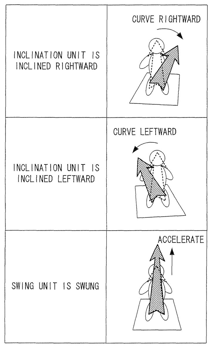
FIG. 17shows an exemplary correspondence between the operation performed by the player and the motion of the character in the modification to the first embodiment. When the first unit is inclined farther from the player than the second unit, the character curves leftward; whereas when the second unit is inclined farther from the player than the first unit, the character curves rightward. When an acceleration button is pressed, the character's motion is accelerated in the advancing direction at that time.
With reference toFIG. 18, a flow of processing executed by the CPU30in the modification to the first embodiment will be described. InFIG. 18, substantially the same processing as that inFIG. 11will bear the same reference numerals and the descriptions thereof will be omitted.
Before step S162, the character curves leftward or rightward in accordance with the inclination difference between the first unit and the second unit.
In step S162, the CPU30determines whether or not the player has pressed the acceleration button. The acceleration button may be provided only in the first unit, only in the second unit or both in the first unit and the second unit. When the player has pressed the acceleration button, the processing is advanced to step S164. When the player has not pressed the acceleration button, the processing is advanced to step S166.
In step S164, the velocity data is increased by a predetermined amount.
In step S166, the velocity data is decreased by a predetermined amount.
After step S164or S166, substantially the same processing as that inFIG. 13is executed.
As described above, according to this modification, the game can be played only using the inclination difference between the first unit and the second unit, without using any absolute value of the inclination of the first unit or the second unit. Therefore, the player can play the game with no problem even while lying on the floor. Thus, the degree of freedom of posture during the game is increased.
(Second Embodiment)
FIG. 19shows an exemplary image displayed in a second embodiment. On the screen of the monitor2, a three-dimensional virtual game world including a character operated by the player (game object) is displayed. In this embodiment, the character is riding on a sleigh, which is pulled by five dinosaurs (dinosaurs A through E). The player can control the motion of the character by swinging the first unit or the second unit. The following description will be given with the premise that the player holds the first unit with his/her left hand and holds the second unit with his/her right hand (the player may hold the first unit with his/her right hand and hold the second unit with his/her left hand).
FIG. 20shows an exemplary correspondence between the operation performed by the player and the motion of the character in the second embodiment. When only the first unit is swung, the character curves rightward (the advancing direction is changed rightward); whereas when only the second unit is swung, the character curves leftward (the advancing direction is changed leftward). When the first unit and the second unit are swung simultaneously, the character's motion is accelerated in the advancing direction at that time.
The game may be set such that when only the first unit is swung, the character advances leftward; when only the second unit is swung, the character advances rightward; and when the first unit and the second unit are swung at the same time, the character advances forward.
FIG. 21shows an exemplary memory map of the main memory33in the second embodiment. The main memory33stores a game program200, game image data202, character control data204, a first swinging strength value206, a second swinging strength value208, a first input flag210, a second input flag212, a simultaneous input flag214, a first timer216, a second timer218, and a simultaneous input timer220.
The game image data202and the character control data204are substantially the same as those in the first embodiment and will not be described here.
The first swinging strength value206represents a swinging strength of the first unit which is detected based on the output value from the first acceleration sensor. The second swinging strength value208represents a swinging strength of the second unit which is detected based on the output value from the second acceleration sensor.
The first flag210is a flag representing that the first unit has been swung, and is turned on when the first unit is detected to have been swung. The second flag212is a flag representing that the second unit has been swung, and is turned on when the second unit is detected to have been swung. The simultaneous input flag214is a flag representing that the first flag and the second unit have been swung simultaneously, and is turned on when the first flag and the second unit are detected to have been swung simultaneously.
The first timer216is a value representing a time period from when the first unit is detected to have been swung (the number of frames). The second timer218is a value representing a time period from when the second unit is detected to have been swung (the number of frames). The simultaneous input timer220is a value representing a time period from when the first unit and the second unit are detected to have been swung simultaneously (the number of frames).
With reference to the flowcharts inFIG. 22throughFIG. 25, a flow of processing executed by the CPU30based on the game program200will be described. The processing in steps S202through S266is repeated frame by frame.
Referring toFIG. 22, when the execution of the game program200is started, in step S200, the CPU30first initializes various data used for the game processing (character control data204, first swinging strength value206, first input flag210, first timer216, etc.), and generates and displays a game image including the character on the screen of the monitor2.
In step S202, it is determined whether or not the simultaneous input flag214is on. When the simultaneous input flag214is on, the processing is advanced to step S204. When the simultaneous input flag214is not on, the processing is advanced to step S210.
In step S204, “1” is added to the simultaneous input timer220.
In step S206, it is determined whether or not the simultaneous input timer220is equal to or greater than 20. When the simultaneous input timer220is equal to or greater than 20, the processing is advanced to step S208. Otherwise, the processing is advanced to step S262inFIG. 24.
In step S208, the simultaneous input flag214is turned off, and the processing is advanced to step S262inFIG. 24.
As described above, after the simultaneous input flag214is turned on (i.e., after the first unit and the second unit are detected to have been swung simultaneously) until a 20 frame time period passes, neither the detection of the swinging strength of the first unit (step S236described later) nor the detection of the swinging strength of the second unit (step S250described later) is performed. Namely, neither the swing operation on the first unit nor the swing operation on the second unit by the player is accepted. Owing to such an arrangement, one swing operation performed by the player is prevented from being detected continuously over a period of a plurality of frames.
In step S210, it is determined whether or not the first input flag210is on. When the first input flag210is on, the processing is advanced to step S212. When the first input flag210is not on, the processing is advanced to step S222.
In step S212, “1” is added to the first timer216.
In step S214, it is determined whether or not the first timer216is 5. When the first timer216is 5 (i.e., when a 5 frame time period has passed after the first unit is detected to have been swung, without any swing of the second unit being detected; namely, when only the first unit was swung), the processing is advanced to step S216. When the first timer216is not 5, the processing is advanced to step S218.
In step S216, the directional vector is changed so as to cause the character to curve rightward. The directional vector can be changed in substantially the same manner as in the first embodiment.
In step S218, it is determined whether or not the first timer216is larger than 10. When the first timer216is larger than 10, the processing is advanced to step S220. When the first timer216is not larger than 10, the processing is advanced to step S222.
In step S220, the first input flag210is turned off.
As described above, after the first input flag210is turned on (i.e., after the first unit is detected to have been swung) until a 10 frame time period passes, the detection of the swinging strength of the first unit (step S236described later) is not performed. Namely, the swing operation on the first unit by the player is not accepted. Owing to such an arrangement, one swing operation performed by the player is prevented from being detected continuously over a period of a plurality of frames.
As described in more detail later, when the second unit is detected to have been swung before a 5 frame time period passes after the first input flag210is turned on, the simultaneous input flag214is turned on at that time. Therefore, until a 20 frame time period passes after that, the swing operation on the first unit performed by the player is not accepted. When the simultaneous input flag214is turned off, the detection of the swinging strength of the first unit (step S236described later) and the detection of the swinging strength of the second unit (step S250described later) are resumed simultaneously. Therefore, the timing at which the acceptance of the swing operation on the first unit is resumed, and the timing at which the acceptance of the swing operation on the second unit is resumed, match each other.
In step S222, it is determined whether or not the second input flag212is on. When the second input flag212is on, the processing is advanced to step S224. When the second input flag212is not on, the processing is advanced to step S234inFIG. 23.
In step S224, “1” is added to the second input timer218.
In step S226, it is determined whether or not the second timer218is 5. When the second timer218is 5 (i.e., when only the second unit was swung), the processing is advanced to step S228. When the second timer218is not 5, the processing is advanced to step S230.
In step S228, the directional vector is changed so as to cause the character to curve leftward.
In step S230, it is determined whether or not the second timer218is larger than 10. When the second timer218is larger than 10, the processing is advanced to step S232. When the second timer218is not larger than 10, the processing is advanced to step S234inFIG. 23.
In step S232, the second input flag212is turned off.
As described above, after the second input flag212is turned on (i.e., after the second unit is detected to have been swung) until a 10 frame time period passes, the detection of the swinging strength of the second unit (step S250described later) is not performed. Namely, the swing operation on the second unit by the player is not accepted. Owing to such an arrangement, one swing operation performed by the player is prevented from being detected continuously over a period of a plurality of frames.
As described in more detail later, when the first unit is detected to have been swung before a 5 frame time period passes after the second input flag212is turned on, the simultaneous input flag214is turned on at that time. Therefore, until a frame time period passes after that, the swing operation on the second unit performed by the player is not accepted. When the simultaneous input flag214is turned off, the detection of the swinging strength of the first unit (step S236described later) and the detection of the swinging strength of the second unit (step S250described later) are resumed simultaneously. Therefore, the timing at which the acceptance of the swing operation on the first unit is resumed, and the timing at which the acceptance of the swing operation on the second unit is resumed, match each other. In other words, in this embodiment, even when the timing at which the first unit is detected to have been swung is slightly offset with respect to the timing at which the second unit is detected to have been swung, it is recognized that the first unit and the second unit were swung simultaneously. Even in this case, the timing at which the acceptance of the swing operation on the first unit is resumed, and the timing at which the acceptance of the swing operation on the second unit is resumed, match each other. Therefore, when the simultaneous swing operation is resumed and then another simultaneous swing operation is performed, the problem that it is detected that only the first unit or the second unit has been swung the second time is avoided. The time period in which the swing is not accepted (swing acceptance prohibition time period) after the simultaneous input flag214is turned on may be a 10 frame time period (same as the swing acceptance prohibition time period after only the first unit or only the second unit is swung). In this embodiment, such a period starts when a later swing operation is detected, among the swing operation on the first unit and the swing operation on the second unit. Alternatively, a period of, for example, 20 frames may start when an earlier swing operation is detected. Still alternatively, such a period may start at an intermediate timing (a timing between the timing at which an earlier swing operation is detected and the timing at which a later swing operation is detected; for example, exactly the middle timing N).
Referring toFIG. 23, in step S234, it is determined whether or not the first input flag210is on. When the first input flag210is on, the processing is advanced to step S248. When the first input flag210is not on, the processing is advanced to step S236.
In step S236, the swinging strength of the first unit is detected. Hereinafter, the detection of the swinging strength of the first unit will be described in detail with reference toFIG. 25.
Referring toFIG. 25, in step S268, an output value (output vector) from an acceleration sensor (here, the first acceleration sensor) is obtained. In this embodiment, the output value in the X axis direction from the first acceleration sensor is Ax, the output value in the Y axis direction from the first acceleration sensor is Ay, and the output value in the Z axis direction from the first acceleration sensor is Az.
In step S270, it is determined whether or not the magnitude of the output vector (Ax, Ay, Az) from the first acceleration sensor obtained in step S268(i.e., √(Ax2+Ay2+Az2) is larger than K (K is a predetermined value). When the magnitude of the output vector from the first acceleration sensor is larger than K (it is determined that a swing operation has been performed), the processing is advanced to step S272. When the magnitude of the output vector from the first acceleration sensor is not larger than K (it is determined that a swing operation has not been performed), the processing is advanced to step S274.
In step S272, the magnitude of the output vector from the first acceleration sensor is returned as a return value X for the detection of the swinging strength. Usually, as the first unit is swung more strongly, the magnitude of the output vector from the first acceleration sensor is larger. Therefore, the return value X reflects the swinging strength of the first unit. Then, the processing is advanced to step S238inFIG. 23. In this embodiment, when the magnitude of the output vector exceeds K, the magnitude of the output vector at that time is immediately returned as the return value X. In a modification, the following processing may be executed. When the magnitude of the output vector exceeds K, a state flag indicating such a state is stored; and the output vector value when the magnitude of the output vector reaches the maximum value (the point at which the magnitude of the output vector starts decreasing after being maximized) may be returned.
In this embodiment, the determination on the swing operation is made based on the magnitude of the output vector being equal to or greater than a predetermined value. The determination may be performed more precisely. This will be described in more detail. When a swing operation is made, the output from the acceleration sensor usually changes as follows. (a) 0→(b) output is increased→(c) maximum→(d) output is decreased→(e) 0→(f) output is increased in the opposite direction→(g) maximum in the opposite direction→(h) output is decreased in the opposite direction→(i) 0.
The history of output values for a predetermined time period from the current point may be always stored, so that it can be detected whether or not the history shows such a change. More simply, it may be detected that the history matches a part of such a change. In this case, which part of the change from (a) through (i) is to be used may be determined arbitrarily (any point other than (a) through (i), for example, a point when the output reaches a predetermined value while being increased, may be used).
Instead of the swing operation, a predetermined motion (an operation for providing a motion of a predetermined pattern) may be detected. Such an operation is, for example, an operation for moving the character in a predetermined direction. In this case also, the history of output values is stored, so that it can be detected whether or not the history matches the predetermined pattern.
The above-described modification is also applicable to embodiments other than the second embodiment.
In step S274, a value representing “no swing operation” is returned as the detection result of the swing operation. Then, the processing is advanced to step S238inFIG. 23.
In step S238, it is determined whether or not the first unit was swung based on the detection result of the swing operation in step S236. When the first unit was swung, the processing is advanced to step S240. When the first unit was not swung, the processing is advanced to step S248.
In step S240, it is determined whether or not the second input flag212is on and also whether or not the second timer218is equal or smaller than 4. When the second input flag212is on and also the second timer218is equal or smaller than 4 (i.e., when the first unit and the second unit were swung substantially simultaneously), the processing is advanced to step S242. When the second input flag212is not on, or the second timer218is larger than 4, the processing is advanced to step S246. When the first unit is swung before a 4 frame time period passes after the second unit is swung, it is determined that “the first unit and the second unit were swung simultaneously” for the following reason. Even if the player intended to swing the first unit and the second unit simultaneously, such swing operations may not necessarily be performed exactly simultaneously. Even when the timing at which the first unit is detected to have been swung is offset by several frames with respect to the timing at which the second unit is detected to have been swung, it is determined that “the first unit and the second unit were swung simultaneously”. Thus, a better operability is obtained.
In step S242, the velocity data of the character is increased in accordance with the return value X for the detection of the swinging strength of the first unit in step S236(value reflecting the swinging strength of the first unit) and the second swinging strength value208which is set in step S260described later (value reflecting the swinging strength of the second unit). For example, the current velocity data may be multiplied by a numerical value in proportion to the return value X and by a numerical value in proportion to the second swinging strength value208so as to determine new velocity data. Alternatively, a numerical value obtained by multiplying the return X by a first coefficient, and a numerical value obtained by multiplying the second swinging strength208by a second coefficient, may be added to the current velocity data (the first coefficient may be the same as, or different from, the second coefficient). Still alternatively, an average of the return value X and the second swinging strength value208is multiplied by a predetermined coefficient, and the resultant value may be added to the current velocity data.
As the return value for the detection of the swinging strength, the magnitude of only the component in a predetermined direction may be used among the output values from the acceleration sensor.
In step S244, the simultaneous input flag214is turned on. The simultaneous input timer220is reset to 0 to resume. The second input flag212is turned off.
In step S246, the first input flag210is turned on. The first input timer216is reset to 0 to resume. The return value X for the detection of the swinging strength of the first unit is set as the first swinging strength value206.
In step S248, it is determined whether or not the second input flag212is on. When the second input flag212is on, the processing is advanced to step S250. When the second input flag212is not on, the processing is advanced to step S262inFIG. 24.
In step S250, the swinging strength of the second unit is detected in substantially the same manner as in step S236. Namely, when the magnitude of the output vector from the second acceleration sensor is larger than K, the magnitude of the output vector from the second acceleration sensor (value reflecting the swinging strength of the second unit) is returned as a return value X for the detection of the swinging strength.
In step S252, it is determined whether or not the second unit was swung based on the detection result of the swing operation in step S250. When the second unit was swung, the processing is advanced to step S254. When the second unit was not swung, the processing is advanced to step S262inFIG. 24.
In step S254, it is determined whether or not the first input flag210is on and also whether or not the first timer216is equal or smaller than 4. When the first input flag210is on and also the first timer216is equal or smaller than 4 (i.e., when the first unit and the second unit were swung substantially simultaneously), the processing is advanced to step S256. When the first input flag210is not on, or the first timer216is larger than 4, the processing is advanced to step S260.
In step S256, the velocity data is increased in accordance with the return value X for the detection of the swinging strength of the second unit in step S250(value reflecting the swinging strength of the second unit) and the first swinging strength value206which was set in step S246above (value reflecting the swinging strength of the first unit). For example, the current velocity data may be multiplied by a numerical value in proportion to the return value X and by a numerical value in proportion to the first swinging strength value208so as to determine new velocity data.
In step S258, the simultaneous input flag214is turned on. The simultaneous input timer220is reset to 0 to resume. The first input flag210is turned off.
In step S260, the second input flag212is turned on. The second input timer218is reset to 0 to resume. The return value X for the detection of the swinging strength of the second unit is set as the second swinging strength value208.
In step S262inFIG. 24, the current position data is updated based on the velocity data and the directional vector. As a result, the character in the game world moves by the distance represented by the velocity data in the direction represented by the directional vector.
In step S264, the game image displayed on the monitor2is updated based on the current position data.
In step S266, the velocity data is decreased by a predetermined amount. This is performed in order to reflect the influence of the friction of the sleigh and the ground on the velocity of the character.
The above-described processing is repeated, so that the game image is changed when necessary in accordance with the operation performed by the player.
As described above, according to this embodiment, the player can freely move both of his/her hands. Owing to a high degree of freedom of motion realized by such an arrangement, a dynamic play is made possible. In addition, the player can control the character by swinging the operation units. Therefore, the player can play intuitively and thus obtain a high operability. As the operation units are swung more strongly, the acceleration of the character is larger. Thus, a more intuitive operation is realized.
In this embodiment, three-axial acceleration sensors are used. Even when one-axial acceleration sensors are used, the swing operations on the operation units and the swinging strength values thereof can be detected (for example, by referring to only the output value in the Z axis direction inFIG. 16, it is detected that the operation units were swung, and the swinging strength values thereof are also detected). Thus, substantially the same effects as those of this embodiment are provided.
(Third Embodiment)
An image displayed in a third embodiment is, for example, substantially the same as the image shown inFIG. 19. In this embodiment, the player can control the motion of the character by swinging the first unit or the second unit.
FIG. 26shows an exemplary correspondence between the operation performed by the player and the motion of the character in the third embodiment. When the first unit is continuously swung, the character curves rightward; whereas when the second unit is continuously swung, the character curves leftward. When the first unit and the second unit are swung alternately, the character's motion is accelerated in the advancing direction at that time.
FIG. 27shows an exemplary memory map of the main memory33in the third embodiment. The main memory33stores a game program300, game image data302, character control data304, operation history information306, and a swinging interval timer308.
The game image data302and the character control data304are substantially the same as those in the first embodiment and will not be described here.
The operation history information306is information representing the type of the operation unit swung by the player (first unit or second unit) regarding the past two swings.
The swinging interval timer308is a value representing a time period from when the player swung the first unit or the second unit immediately previously (the number of frames).
With reference to the flowcharts inFIG. 28throughFIG. 30, a flow of processing executed by the CPU30based on the game program300will be described.
Referring toFIG. 28, when the execution of the game program300is started, in step S300, the CPU30first initializes various data used for the game processing (character control data304, operation history information306, swinging interval timer308, etc.), and generates and displays a game image including the character on the screen of the monitor2.
In step S302, the swinging strength of the first unit is detected. Hereinafter, the detection of the swinging strength of the first unit will be described in detail with reference toFIG. 30.
Referring toFIG. 30, in step S346, an output value (output vector) from an acceleration sensor (here, the first acceleration sensor) is obtained. In this embodiment, the output value in the X axis direction from the first acceleration sensor is Ax, the output value in the Y axis direction from the first acceleration sensor is Ay, and the output value in the Z axis direction from the first acceleration sensor is Az.
In step S348, it is determined whether or not the magnitude of the output vector (Ax, Ay, Az) from the first acceleration sensor obtained in step S346is larger than K (K is a predetermined value). When the magnitude of the output vector from the first acceleration sensor is larger than K, the processing is advanced to step S350. When the magnitude of the output vector from the first acceleration sensor is not larger than K, the processing is advanced to step S352.
In step S350, a value representing that “a swing operation was performed” is returned as the detection result of the swing operation. Then, the processing is advanced to step S304inFIG. 28.
In step S352, a value representing “no swing operation” is returned as the detection result of the swing operation. Then, the processing is advanced to step S304inFIG. 28.
In step S304, it is determined whether or not the first unit was swung based on the detection result of the swing operation in step S302. When the first unit was swung, the processing is advanced to step S306. When the first unit was not swung, the processing is advanced to step S318inFIG. 29.
In step S306, the operation history information306is updated. Specifically, the pre-update value of the “operation unit swung currently” is set as the “operation unit swung immediately previously”, and then the value representing the first unit is set as the “operation unit swung currently”.
In step S308, the swinging interval timer308is reset to 0.
In step S310, it is determined whether or not the swing operation detected currently is “the first swing of the continuous swing operation”. Specifically, the operation history information306is referred to. When neither the value representing the first unit nor the value representing the second unit is stored in the “operation unit swung immediately previously”, it is determined that the swing operation detected currently is “the first swing of the continuous swing operation”. In this embodiment, when the interval between the immediately previous swing operation and the current swing operation exceeds a 60 frame time period, it is determined that the swing operation detected currently is “the first swing of the continuous swing operation”. When the swing operation detected currently is “the first swing of the continuous swing operation”, the processing is advanced to step S318inFIG. 29. Otherwise, the processing is advanced to step S312.
In step S312, it is determined whether or not the operation unit swung immediately previously is the first unit, by referring to the operation history information306. When the operation unit swung immediately previously is the first unit (i.e., when the first unit is continuously swung), the processing is advanced to step S316. When the operation unit swung immediately previously is not the first unit (i.e., when the operation unit swung immediately previously is the second unit; namely, the first unit and the second unit are swung alternately), the processing is advanced to step S314.
In step S314, the velocity data is increased by a predetermined amount. In a modification, the following processing may be executed. When the swing operation of the first unit is detected in step S302, the swinging strength is also detected as in the second embodiment. The velocity data is increased more largely as the swinging strength is greater. Alternatively, the swinging strength when the operation unit was swung immediately previously is stored, and the velocity data is increased based both on the immediately previous swinging strength and the current swinging strength of the first unit. (For example, the increasing amount of the velocity data is determined based on the sum or average of the two swinging strength values. A weighted average may be used; for example, the coefficient is decreased as the swinging strength data is older.) Still alternatively, as long as the first unit and the second unit are continuously swung alternately, the increasing amount of the velocity data is determined based on the sum or average of the swinging strength values of such a plurality of swings.
In step S316, the directional vector is changed so as to cause the character to curve rightward. In this step also, the following processing may be executed. As the swinging strength is greater, the character may curve at a larger angle. Alternatively, the swinging strength when the operation unit was swung immediately previously is stored, and the velocity data is increased based both on the immediately previous swinging strength and the current swinging strength of the first unit. Still alternatively, as long as the first unit and the second unit are continuously swung alternately, the angle of curving is determined based on the sum or average of the swinging strength values of such a plurality of swings.
Referring toFIG. 29, in step S318, the swing operation of the second unit is detected as in step S302.
In step S320, it is determined whether or not the second unit was swung based on the detection result of the swing operation in step S318. When the second unit was swung, the processing is advanced to step S322. When the second unit was not swung, the processing is advanced to step S334.
In step S322, the operation history information306is updated. Specifically, the pre-update value of the “operation unit swung currently” is set as the “operation unit swung immediately previously”, and then the value representing the second unit is set as the “operation unit swung currently”.
In step S324, the swinging interval timer308is reset to 0.
In step S326, it is determined whether or not the swing operation detected currently is “the first swing of the continuous swing operation”. When the swing operation detected currently is “the first swing of the continuous swing operation”, the processing is advanced to step S334. Otherwise, the processing is advanced to step S328.
In step S328, it is determined whether or not the operation unit swung immediately previously is the second unit, by referring to the operation history information306. When the operation unit swung immediately previously is the second unit (i.e., when the second unit is continuously swung), the processing is advanced to step S332. When the operation unit swung immediately previously is not the second unit (i.e., when the operation unit swung immediately previously is the first unit; namely, the first unit and the second unit are swung alternately), the processing is advanced to step S330.
In step S330, the velocity data is increased by a predetermined amount. In a modification, when the swing operation of the second unit is detected in step S318, the swinging strength may also be detected as in the second embodiment, so that the velocity data can be increased more largely as the swinging strength is greater.
In step S332, the directional vector is changed so as to cause the character to curve leftward. In this step also, as the swinging strength is greater, the character may curve at a larger angle.
In step S334, “1” is added to the swinging interval timer308.
In step S336, it is determined whether or not the swinging interval timer308exceeds 60. When the swinging interval timer308exceeds 60, the processing is advanced to step S338. When the swinging interval timer308does not exceed 60, the processing is advanced to step S340.
In step S338, the operation history information306is cleared.
In step S340, the current position data is updated based on the velocity data and the directional vector. As a result, the character in the game world moves by the distance represented by the velocity data in the direction represented by the directional vector.
In step S342, the game image displayed on the monitor2is updated based on the current position data.
In step S344, the velocity data is decreased by a predetermined amount. Then, the processing is returned to step S302inFIG. 28.
As described above, according to this embodiment, the player can freely move both of his/her hands. Owing to a high degree of freedom of motion realized by such an arrangement, a dynamic play is made possible. In addition, the player can control the character by swinging the operation units. Therefore, the player can play intuitively and thus obtain a high operability.
In this embodiment, three-axial acceleration sensors are used. As in the second embodiment, even when one-axial acceleration sensors are used, substantially the same effects as those of this embodiment can be provided.
In this embodiment, it is detected whether the first unit is continuously swung, the second unit is continuously swung, or the first unit and the second unit are alternately swung. Then, the game control is performed in accordance with the detection result. In a modification, it may be detected whether or not the continuous swinging is of a predetermined pattern. For example, predetermined game processing (for example, processing of allowing the character to make an attack) may be executed when a pattern of “the swing of the first unit→the swing of the second unit→the swing of the second unit→the swing of the first unit” is detected. (The pattern is not limited to this, and any other appropriate pattern may be set.)
In this embodiment, when the interval between two continuous swing operations is within a predetermined time period (for example, within a 60 frame time period), it is determined that the first unit and the second unit are alternately swung. The present technology is not limited to this. When a swing is made within a predetermined time period after the first swing, it may be determined that the same operation unit is continuously swung or two operation units are alternately swung. Alternatively, as the same operation unit is continuously swung for a longer time period, the interval for determining whether the swings are made continuously or alternately may be extended (or shortened).
(Fourth Embodiment)
An image displayed in a fourth embodiment is, for example, substantially the same as the image shown inFIG. 19. In this embodiment, one of the first unit and the second unit is used as an inclination unit, and the other is used as a swing unit. The player can control the motion of the character by inclining the inclination unit or by swinging the swing unit.
FIG. 31shows an exemplary correspondence between the operation performed by the player and the motion of the character in the fourth embodiment. When the inclination unit is inclined rightward, the character curves rightward; whereas when the inclination unit is inclined leftward, the character curves leftward. When the swing unit is swung, the character's motion is accelerated in the advancing direction at that time.
FIG. 32shows an exemplary memory map of the main memory33in the fourth embodiment. The main memory33stores a game program400, game image data402, character control data404, inclination unit designation data406, and swing unit designation data408.
The game image data402and the character control data404are substantially the same as those in the first embodiment and will not be described here.
The inclination unit designation data406is data representing which of the first unit and the second unit is to be used as the inclination unit. The swing unit designation data408is data representing which of the first unit and the second unit is to be used as the swing unit.
With reference to the flowcharts inFIG. 33throughFIG. 35, a flow of processing executed by the CPU30based on the game program400will be described.
Referring toFIG. 33, when the execution of the game program400is started, in step S400, the CPU30first initializes various data used for the game processing (character control data404, etc.), and stores “1” representing the first unit in the inclination unit designation data406as an initial value and stores “2” representing the second unit in the swing unit designation data408as an initial value. The CPU30also generates and displays a game image including the character on the screen of the monitor2.
In step S402, it is determined whether or not the player has input a unit role exchange instruction using an operation button or the like. When a unit role exchange has been instructed, the processing is advanced to step S404. When no unit role exchange has been instructed, the processing is advanced to step S406.
In step S404, the value of the inclination unit designation data406and the value of the swing unit designation data408are exchanged.
Owing to the above-described processing, the player can optionally change the role of the first unit and the role of the second unit in accordance with his/her preference or the situation in the game. Such an exchange of the role of the first unit and the second is also applicable to the other embodiments in substantially the same manner.
In step S406, an inclination of the inclination unit is detected. Hereinafter, the detection of the inclination of the inclination unit will be described in detail with reference toFIG. 34.
Referring toFIG. 34, in step S424, an output value (output vector) from an acceleration sensor provided in the inclination unit is obtained. In this embodiment, the output value in the X axis direction from the acceleration sensor is Ax, the output value in the Y axis direction from the acceleration sensor is Ay, and the output value in the Z axis direction from the acceleration sensor is Az.
In step S426, it is determined whether or not the magnitude of the output vector (Ax, Ay, Az) from the acceleration sensor obtained in step S424is within the range of 0.8 to 1.2. When the magnitude of the output vector from the acceleration sensor is within the range of 0.8 to 1.2, the processing is advanced to step S428. When the magnitude of the output vector from the acceleration sensor is not within the range of 0.8 to 1.2, the processing is advanced to step S430.
In step S428, arctan (Az/Ay), which represents the inclination of the inclination unit around the Z axis (represented by angle θ inFIG. 36), is calculated, and the calculated value is returned as a return value for the detection of the inclination. Then, the processing is advanced to step S408inFIG. 33.
In step S430, an error is returned as the detection result of the inclination. Thus, the detection of the inclination is terminated, and the processing is advanced to step S408.
In step S408, it is determined whether or not the detection result of the inclination in step S430is an error. When the result is an error, the processing is advanced to step S412. When the result is not an error, the processing is advanced to step S410.
In step S410, the directional vector is changed in accordance with the return value θ of the detection result of the inclination in step S406. The directional vector can be changed by various methods. In this embodiment, for example, the method shown inFIG. 37is used. The current directional vector is rotated by the return value θ around the rotation axis, which is the normal vector to the ground at the current position of the character. The resultant vector is determined as a new directional vector.
In step S412, a swing operation of the swing unit is detected. Hereinafter, the detection of the swing operation will be described in detail with reference toFIG. 35.
Referring toFIG. 35, in step S432, an output value (output vector) from an acceleration sensor provided in the swing unit is obtained. In this embodiment, the output value in the X axis direction from the acceleration sensor is Ax, the output value in the Y axis direction from the acceleration sensor is Ay, and the output value in the Z axis direction from the acceleration sensor is Az.
In step S434, it is determined whether or not the magnitude of the output vector (Ax, Ay, Az) from the acceleration sensor obtained in step S432is larger than K (K is a predetermined value). When the magnitude of the output vector from the acceleration sensor is larger than K, the processing is advanced to step S436. When the magnitude of the output vector from the acceleration sensor is not larger than K, the processing is advanced to step S438.
In step S436, a value representing that “a swing operation was performed” is returned as the detection result of the swing operation. Then, the processing is advanced to step S414inFIG. 33.
In step S438, a value representing “no swing operation” is returned as the detection result of the swing operation. Then, the processing is advanced to S414inFIG. 33.
In step S414, it is determined whether or not the swing unit was swung based on the detection result of the swing operation in step S412. When the swing unit was swung, the processing is advanced to step S416. When the swing unit was not swung, the processing is advanced to step S418.
In step S416, the velocity data is increased by a predetermined amount. In a modification, the following processing may be executed. When the swing operation of the swing unit is detected in step S412, the swinging strength is also detected as in the second embodiment. The velocity data is increased more largely as the swinging strength is greater.
In step S418, the current position data is updated based on the velocity data and the directional vector. As a result, the character in the game world moves by the distance represented by the velocity data in the direction represented by the directional vector.
In step S420, the game image displayed on the monitor2is updated based on the current position data.
In step S422, the velocity data is decreased by a predetermined amount. Then, the processing is returned to step S402.
As described above, according to this embodiment, the player can freely move both of his/her hands. Owing to a high degree of freedom of motion realized by such an arrangement, a dynamic play is made possible. In addition, the character can curve by inclining the inclination unit and accelerated by swinging the swing unit. Therefore, the player can play intuitively and thus obtain a high operability.
In this embodiment, three-axial acceleration sensors are used. As in the first and second embodiments, even when one-axial acceleration sensors are used, substantially the same effects as those of this embodiment can be provided.
As described later, when the swing unit is swung, the swinging direction may be detected, so that the direction or the magnitude of acceleration of the character can be changed in accordance with the detected direction.
(Fifth Embodiment)
An image displayed in a fifth embodiment is, for example, substantially the same as the image shown inFIG. 19. In this embodiment, the motion of the character is controlled based on the direction in which the first unit and the second unit are swung (moved).
FIG. 38shows an exemplary correspondence between the operation performed by the player and the motion of the character in the fifth embodiment. When either the first unit or the second unit is swung obliquely rightward and farther from the player (right-forward; “forward” is the direction in which the player is directed), the character is accelerated slightly right-forward; whereas when either the first unit or the second unit is swung obliquely leftward and closer to the player (left-rearward; “rearward” is the direction opposite to the direction in which the player is directed), the character is accelerated slightly left-rearward. In this embodiment, the character is basically accelerated in a direction (direction based on the forward direction with respect to the character in the virtual space) corresponding to the direction in which the operation unit is swung (direction based on the forward direction with respect to the player in the real world).
When the first unit and the second unit are simultaneously swung obliquely rightward and farther from the player, the character is accelerated largely right-forward. In this embodiment, when the first unit and the second unit are simultaneously swung in the same direction, the character is accelerated largely.
When one of the first unit and the second unit is swung rightward and the other unit is swung farther from the player, the character is accelerated slightly right-forward. In this embodiment, when the first unit and the second unit are simultaneously swung in different directions, the acceleration direction of the character is determined based on a direction obtained by synthesizing the swinging direction of the first unit and the swinging direction of the second unit.
When the first unit and the second unit are swung simultaneously in opposite directions, the character stops.
FIG. 39shows an exemplary memory map of the main memory33in the fifth embodiment. The main memory33stores a game program500, game image data502, character control data504, a first swinging directional vector506, a second swinging directional vector508, a first input flag510, a second input flag512, a simultaneous input flag514, a first timer516, a second timer518, a simultaneous input timer520, first sampling data522, and second sampling data524.
The game image data502is substantially the same as that described in the first embodiment and will not be described here.
The character control data504includes current position data, velocity vector representing the magnitude and the direction of the moving speed of the character, and a posture matrix representing the posture of the character. The current position data is represented by a three-dimensional coordinate value, and the velocity vector is represented by a three-dimensional vector. The posture matrix is a set of a forward vector which is a three-dimensional unit vector representing the forward direction with respect to the character, a rightward vector which is a three-dimensional unit vector representing the rightward direction with respect to the character, and an upward vector which is a three-dimensional unit vector representing the upward direction with respect to the character.
The first swinging directional vector506represents a direction in which the first unit is swung by the player. The second swinging directional vector508represents a direction in which the second unit is swung by the player.
The first input flag510, the second input flag512, the simultaneous input flag514, the first timer516, the second timer518, and the simultaneous input timer520are substantially the same as those in the second embodiment and will not be described here.
The first sampling data522is sampling data on outputs from the first acceleration sensor provided in the first unit for the immediately previous 60 frames. The second sampling data524is sampling data on outputs from the second acceleration sensor provided in the second unit for the immediately previous 60 frames.
With reference to the flowcharts inFIG. 40throughFIG. 44, a flow of processing executed by the CPU30based on the game program500will be described.
Referring toFIG. 40, when the execution of the game program500is started, in step S500, the CPU30first initializes various data used for the game processing (character control data504, first swinging directional vector506, first input flag510, first timer516, first sampling data522, etc.), and generates and displays a game image including the character on the screen of the monitor2.
In step S502, an output value from the first acceleration sensor and an output value from the second acceleration sensor are obtained, and thus the first sampling data522and the second sampling data524are updated.
In step S504, it is determined whether or not the simultaneous input flag514is on. When the simultaneous input flag514is on, the processing is advanced to step S506. When the simultaneous input flag514is not on, the processing is advanced to step S512.
In step S506, “1” is added to the simultaneous input timer520.
In step S508, it is determined whether or not the simultaneous input timer520is equal to or greater than 20. When the simultaneous input timer520is equal to or greater than 20, the processing is advanced to step S510. Otherwise, the processing is advanced to step S596inFIG. 43.
In step S510, the simultaneous input flag514is turned off, and the processing is advanced to step S596inFIG. 43.
In step S512, it is determined whether or not the first input flag510is on. When the first input flag510is on, the processing is advanced to step S514. When the first input flag510is not on, the processing is advanced to step S526.
In step S514, “1” is added to the first timer516.
In step S516, it is determined whether or not the first timer516is 5. When the first timer516is 5 (i.e., when only the first unit was swung), the processing is advanced to step S518. When the first timer516is not 5, the processing is advanced to step S522.
In step S518, the velocity vector is changed based on the first swinging directional vector506detected in the step of detecting the swinging direction of the first unit (step S542described later). The velocity vector can be changed by various methods. In this embodiment, for example, the method shown inFIG. 45is used. Where an X axis value of the first swinging directional vector506is a1and a Z axis value thereof is b1, the current vector is synthesized with a vector represented by (rightward vector×a1+forward vector×b1). The resultant vector is determined as a new velocity vector. Therefore, as the X axis value of the first swinging directional vector506is larger, the character is accelerated in the direction of the rightward vector more largely. As the Z axis value of the first swinging directional vector506is larger, the character is accelerated in the direction of the forward vector more largely.
In step S520, the posture matrix is updated such that the direction of the forward vector matches the direction of the velocity vector updated in step S518.
In step S522, it is determined whether or not the first timer516is larger than 10. When the first timer516is larger than 10, the processing is advanced to step S524. When the first timer516is not larger than 10, the processing is advanced to step S526.
In step S524, the first input flag510is turned off.
In step S526, it is determined whether or not the second input flag512is on. When the second input flag512is on, the processing is advanced to step S528. When the second input flag512is not on, the processing is advanced to step S540inFIG. 41.
In step S528, “1” is added to the second input timer518.
In step S530, it is determined whether or not the second timer518is 5. When the second timer518is 5 (i.e., when only the second unit was swung), the processing is advanced to step S532. When the second timer518is not 5, the processing is advanced to step S536.
In step S532, the velocity vector is changed based on the second swinging directional vector508detected in the step of detecting the swinging direction of the second unit (step S570described later), by substantially the same method as in step S518.
In step S534, the posture matrix is updated such that the direction of the forward vector matches the direction of the velocity vector updated in step S532.
In step S536, it is determined whether or not the second timer518is larger than 10. When the second timer518is larger than 10, the processing is advanced to step S538. When the second timer518is not larger than 10, the processing is advanced to step S540inFIG. 41.
In step S538, the second input flag512is turned off.
Referring toFIG. 41, in step S540, it is determined whether or not the first input flag510is on. When the first input flag510is on, the processing is advanced to step S568. When the first input flag510is not on, the processing is advanced to step S542.
In step S542, the swinging direction of the first unit is detected. Hereinafter, the detection of the swinging direction of the first unit will be described in detail with reference toFIG. 44.
Referring toFIG. 44, in step S604, the first sampling data522is referred to. It is determined whether or not the magnitude of the vector represented by the X axis value and the Z axis value of the second newest detected value from the first acceleration sensor (Ax, Ay, Az) (the magnitude is √(Ax2+Az2) is larger than L (L is a predetermined value). (Hereinafter, such a vector represented by an X axis value and a Z axis value will be referred to as an “XZ vector”.) When the magnitude of the XZ vector is larger than L (i.e., when the first unit is determined to have been swung), the processing is advanced to step S606. When the magnitude of the XZ vector is not larger than L (i.e., when the first unit is determined not to have been swung), the processing is advanced to step S610.
In step S606, the first sampling data522is referred to. It is determined whether or not the magnitude of the XZ vector of the second newest detected value from the first acceleration sensor is larger than the magnitude of the XZ vector of the newest detected value from the first acceleration sensor. This is performed in order to detect the timing at which the maximum force was applied to the first acceleration sensor in a direction parallel to the XZ plane. When the player swings the first unit in a direction parallel to the XZ plane, a large force is applied to the first unit (first acceleration sensor) by the player immediately after the start of the swing and immediately before the end of the swing. Therefore, the magnitude of the XZ vector of the detected value regarding the first acceleration sensor is maximum immediately after the start of the swing and immediately before the end of the swing. When the magnitude of the XZ vector of the second newest detected value from the first acceleration sensor is larger than the magnitude of the XZ vector of the newest detected value from the first acceleration sensor (i.e., immediately after the magnitude of the XZ vector of the detected value regarding the first acceleration sensor is maximized), the processing is advanced to step S608. Otherwise, the processing is advanced to step S610.
In step S608, the XZ vector (Ax, Az) of the second newest detected value from the first acceleration sensor is returned as a return value for the detection of the swinging direction. The XZ vector (Ax, Az) represents the direction in which the force was applied to the first unit when the player swung the first unit (i.e., the direction in which the first unit was swung). Then, the processing is advanced to step S544inFIG. 41.
Alternatively, the swinging direction may be detected by averaging the XZ vectors during the time period in which the XZ vector is larger than L.
The XZ vector detected by the direction of the swinging direction may be sometimes opposite to the actual swinging direction of the operation unit when a certain detection method is used. In such a case, a value obtained by multiplying the detected XZ vector by −1 may be returned as a return value for the detection of the swinging direction.
In step S610, a value representing “no swing operation” is returned as the detection result of the swing direction. Then, the processing is advanced to step S544inFIG. 41.
In step S544, it is determined whether or not the first unit was swung based on the detection result of the swing direction in step S542. When the first unit was swung, the processing is advanced to step S546. When the first unit was not swung, the processing is advanced to step S568.
In step S546, the return value for the direction of the swinging direction in step S542(i.e., a vector representing the swinging direction of the first unit) is set as the first swinging directional vector506.
In step S548, it is determined whether or not the second input flag512is on and also whether or not the second timer518is equal or smaller than 4. When the second input flag512is on and also the second timer518is equal or smaller than 4 (i.e., when the first unit and the second unit were swung substantially simultaneously), the processing is advanced to step S550. When the second input flag512is not on, or the second timer518is larger than 4, the processing is advanced to step S566.
In step S550, it is determined whether or not an angle made by the first swinging directional vector506and the second swinging directional vector508(a vector representing the swinging direction of the second unit) which is set in step S574described later is within the range of −30° to 30°. When the angle made by the first swinging directional vector506and the second swinging directional vector508is within the range of −30° to 30° (i.e., when the first unit and the second unit were swung in substantially the same direction), the processing is advanced to step S552. When the angle made by the first swinging directional vector506and the second swinging directional vector508is not within the range of −30° to 30°, the processing is advanced to step S558. The range of −30° to 30° is merely exemplary, and the range may be wider or narrower. Any range by which the first unit and the second unit are regarded as being swung in substantially the same direction is usable.
In step S552, the velocity vector is changed based on the first swinging directional vector506and the second swinging directional vector508. The velocity vector can be changed by various methods. In this embodiment, for example, the method shown inFIG. 46is used. The first swinging directional vector506and the second swinging directional vector508are synthesized to obtain a synthesized swinging directional vector. Where an X axis value of the synthesized swinging directional vector is a3and a Z axis value thereof is b3, the current vector and a vector represented by (rightward vector×a3+forward vector×b3)×α (predetermined constant) are synthesized. The resultant vector is determined as a new velocity vector. α is a constant, and in step S552, α=2. Namely, in step S552, the new velocity vector is determined by synthesizing the current vector with a vector obtained by doubling the magnitude of the synthesized swinging directional vector. In step S552, a vector obtained by doubling the magnitude of the first swinging directional vector506or the second swinging directional vector508may be regarded as the synthesized vector.
In step S554, the posture matrix is updated such that the direction of the forward vector matches the direction of the velocity vector updated in step S552.
In step S556, the simultaneous input flag514is turned on. The simultaneous input timer520is reset to 0. The second input flag512is turned off. In step S558, it is determined whether or not an angle made by the first swinging directional vector506and the second swinging directional vector508is either within the range of 150° to 180° or within the range of −150° to −180°. When the angle made by the first swinging directional vector506and the second swinging directional vector508is either within the range of 150° to 180° or within the range of −150° to −180° (i.e., when the first unit and the second unit were swung in substantially the opposite directions), the processing is advanced to step S560. When the angle made by the first swinging directional vector506and the second swinging directional vector508is neither within the range of 150° to 180° nor within the range of −150° to −180°, the processing is advanced to step S562. The ranges of 150° to 180° and −150° to −180° are merely exemplary, and the ranges may be wider or narrower. Any ranges by which the first unit and the second unit are regarded as being swung in substantially the opposite directions are usable.
In step S560, the velocity vector is changed to 0, and the processing is advanced to step S556.
In step S562, as in step S552, the first swinging directional vector506and the second swinging directional vector508are synthesized to obtain a synthesized swinging directional vector. Where an X axis value of the synthesized swinging directional vector is a3and a Z axis value thereof is b3, the current vector and a vector represented by (rightward vector×a3+forward vector×b3)×α (predetermined constant) are synthesized. The resultant vector is determined as a new velocity vector. In step S562, α=1.5. Namely, in step S562, the new velocity vector is determined by synthesizing the current vector with a vector obtained by multiplying the magnitude of the synthesized swinging directional vector by 1.5.
In step S564, the posture matrix is updated such that the direction of the forward vector matches the direction of the velocity vector updated in step S562.
In step S566, the first input flag510is turned on. The first input timer516is reset to 0.
Referring toFIG. 42, in step S568, it is determined whether or not the second input flag512is on. When the second input flag512is on, the processing is advanced to step S596inFIG. 43. When the second input flag512is not on, the processing is advanced to step S570.
In step S570, the swinging direction of the second unit is detected. Hereinafter, the detection of the swinging direction of the second unit will be described in detail with reference toFIG. 44.
Referring toFIG. 44, in step S604, the second sampling data524is referred to. It is determined whether or not the magnitude of the XZ vector of the second newest detected value from the second acceleration sensor is larger than L. When the magnitude of the XZ vector is larger than L (i.e., when the second unit is determined to have been swung), the processing is advanced to step S606. When the magnitude of the XZ vector is not larger than L (i.e., when the second unit is determined not to have been swung), the processing is advanced to step S610.
In step S606, the second sampling data524is referred to. It is determined whether or not the magnitude of the XZ vector of the second newest detected value from the second acceleration sensor is larger than the magnitude of the XZ vector of the newest detected value from the second acceleration sensor. When the magnitude of the XZ vector of the second newest detected value from the second acceleration sensor is larger than the magnitude of the XZ vector of the newest detected value from the second acceleration sensor (i.e., immediately after the magnitude of the XZ vector of the detected value regarding the second acceleration sensor is maximized), the processing is advanced to step S608. Otherwise, the processing is advanced to step S610.
In step S608, the XZ vector (Ax, Az) of the second newest detected value from the second acceleration sensor is returned as a return value for the detection of the swinging direction. The XZ vector (Ax, Az) represents the direction in which the force was applied to the second unit when the player swung the second unit (i.e., the direction in which the second unit was swung). Then, the processing is advanced to step S572inFIG. 42.
In step S610, a value representing “no swing operation” is returned as the detection result of the swing direction. Then, the processing is advanced to step S572inFIG. 42.
In step S572, it is determined whether or not the second unit was swung based on the detection result of the swing direction in step S570. When the second unit was swung, the processing is advanced to step S574. When the second unit was not swung, the processing is advanced to step S596.
In step S574, the return value for the direction of the swinging direction in step S570(i.e., a vector representing the swinging direction of the second unit) is set as the second swinging directional vector508.
In step S576, it is determined whether or not the first input flag510is on and also whether or not the first timer516is equal or smaller than 4. When the first input flag510is on and also the first timer516is equal or smaller than 4 (i.e., when the first unit and the second unit were swung substantially simultaneously), the processing is advanced to step S578. When the first input flag510is not on, or the first timer516is larger than 4, the processing is advanced to step S594.
In step S578, it is determined whether or not an angle made by the first swinging directional vector506and the second swinging directional vector508is within the range of −30° to 30°. When the angle made by the first swinging directional vector506and the second swinging directional vector508is within the range of −30° to 30° (i.e., when the first unit and the second unit were swung in substantially the same direction), the processing is advanced to step S580. When the angle made by the first swinging directional vector506and the second swinging directional vector508is not within the range of −30° to 30°, the processing is advanced to step S586.
In step S580, as in step S552, a new velocity vector is determined by synthesizing the current vector and a vector obtained by doubling the magnitude of the synthesized swinging directional vector.
In step S582, the posture matrix is updated such that the direction of the forward vector matches the direction of the velocity vector updated in step S580.
In step S584, the simultaneous input flag514is turned on. The simultaneous input timer520is reset to 0. The first input flag510is turned off.
In step S586, it is determined whether or not an angle made by the first swinging directional vector506and the second swinging directional vector508is within the range of 150° to 180° or within the range of −150° to −180°. When the angle made by the first swinging directional vector506and the second swinging directional vector508is within the range of 150° to 180° or within the range of −150° to −180° (i.e., when the first unit and the second unit were swung in substantially the opposite directions), the processing is advanced to step S588. When the angle made by the first swinging directional vector506and the second swinging directional vector508is neither within the range of 150° to 180° nor within the range of −150° to −180°, the processing is advanced to step S590.
In step S588, the velocity vector is changed to 0, and the processing is advanced to step S584.
In step S590, as in step S562, a new velocity vector is determined by synthesizing the current vector and a vector obtained by multiplying the magnitude of the synthesized swinging directional vector by 1.5.
In step S592, the posture matrix is updated such that the direction of the forward vector matches the direction of the velocity vector updated in step S590.
In step S594, the second input flag512is turned on. The second input timer518is reset to 0.
Referring toFIG. 43, in step S596, the current position data is updated based on the velocity vector.
In step S598, the game image displayed on the monitor2is updated based on the current position data and the posture matrix.
In step S600, the posture matrix and the velocity vector are updated so as to reflect the influence of the topography. This is performed such that, for example, when the character goes up a steep slope, the character inclines its body slightly backward and the advancing direction of the character is along the slope.
In step S602, the velocity data is decreased by a predetermined amount. Then, the processing is returned to step S502inFIG. 40.
The above-described processing is repeated, so that the game image is changed when necessary in accordance with the operation performed by the player.
The processing in this embodiment can be summarized as follows.
(1) When the first unit and the second unit are swung at different timings→the velocity vector is updated based on the directional vectors of the respective units.
(2) When the first unit and the second unit are swung substantially simultaneously in substantially the same direction→the velocity vector is updated based on a vector obtained by doubling the magnitude of the synthesized swinging directional vector.
(3) When the first unit and the second unit are swung substantially simultaneously in different directions (excluding substantially the opposite directions)→the velocity vector is updated based on a vector obtained by multiplying the magnitude of the synthesized swinging directional vector by 1.5.
(4) When the first unit and the second unit are swung substantially simultaneously in substantially opposite directions→the velocity vector is made 0 (the character stops).
In this manner, the game processing is made in different manners based on the swinging timing and the relative directions of the first unit and the second unit. This allows the player to make various inputs.
As described above, according to this embodiment, the player can freely move both of his/her hands. Owing to a high degree of freedom of motion realized by such an arrangement, a dynamic play is made possible. Since the player can control the character by swinging the operation units, the player can play intuitively and thus obtain a high operability. As the swing directions of two operation units swung simultaneously are closer to each other, the acceleration of the character is larger. Therefore, a more intuitive operation is realized.
In this embodiment, three-axial acceleration sensors are used. Even when two-axial acceleration sensors are used, the swinging directions of the operation units can be detected (for example, in the flow shown inFIG. 44, it is detected that the operation units were swung, and the swinging directions thereof are also detected, by referring to the output values in the two axes of the X axis and the Z axis). Thus, substantially the same effects as those of this embodiment are provided.
In this embodiment, one of the first unit and the second unit is swung, the character is accelerated in accordance with the swinging direction thereof. Alternatively, the game may be set such that when one of the first unit and the second unit is swung, the character is not accelerated; whereas when the first unit and the second unit are substantially simultaneously swung, the character is accelerated.
In this embodiment, when it is detected that the output from the acceleration sensor (specifically the XZ vector in this embodiment) is maximized, the swinging direction of the operation unit is detected based on the output from the acceleration sensor at that time or the vicinity thereof. The present invention is not limited to this. The swinging direction of the operation unit may be detected by any other method. For example, the following methods are usable. When the magnitude of the XZ vector from the acceleration sensor exceeds a predetermined value and then returns to 0, the sampling data during that time period is referred to, and thus the maximum value of the XZ vector from the acceleration sensor during that period may be set as the swinging directional vector. A vector obtained by averaging or synthesizing the XZ vectors during that period may be set as the swinging directional vector. Alternatively, the outputs from the acceleration sensor are integrated to calculate the moving speed of the operation unit. The swinging direction of the operation unit may be detected based on the outputs from the acceleration sensor during the time period in which the moving speed calculated in this manner is equal to or larger than a predetermined value.
In this embodiment, the swing operation is detected. The present invention is not limited to this. A motion of the operation unit may be detected, in which case the game control may be executed based on the direction and the timing of the motion.
(Sixth Embodiment)
An image displayed in a sixth embodiment is, for example, substantially the same as the image shown inFIG. 19. In this embodiment, the motion of the character is controlled based on the direction in which the first unit and the second unit are swung.
FIG. 47shows an exemplary manner of operating the operation units in the sixth embodiment. In this embodiment, the player instructs a direction by performing a direction instruction operation (an operation of moving the operation unit horizontally), and then determines the direction which was input by the direction instruction operation by performing a trigger operation (an operation of moving the operation unit vertically downward). The correspondence between the direction in which the first unit and the second unit are moved by the direction instruction operation and the motion of the character is substantially the same as that shown inFIG. 38except for several points. Hereinafter, a swing operation is used as an example of the operation for moving the operation units. The present invention is not limited to this, and any operation is usable as long as the motions of the operation units are detected and the motion of the character is controlled based on the direction and the magnitude of the detected motions.
FIG. 48shows an exemplary memory map of the main memory33in the sixth embodiment. The main memory33stores a game program703, game image data704, character control data705, a first swinging directional vector709, a second swinging directional vector710, a first input flag711, a second input flag712, a simultaneous input flag714, a first timer716, a second timer718, a simultaneous input timer720, first sampling data722, second sampling data724, a first trigger operation strength value726, and a second trigger operation strength value728.
The game image data704, the character control data705, the first swinging directional vector709, the second swinging directional vector710, the first input flag711, the second input flag712, the simultaneous input flag714, the first timer716, the second timer718, the simultaneous input timer720, first sampling data722, and second sampling data724are substantially the same as those in the fifth embodiment and will not be described here.
The first trigger operation strength value726represents a swinging strength when a trigger operation is made on the first unit. The second trigger operation strength value728represents a swinging strength when a trigger operation is made on the second unit.
With reference to the flowcharts inFIG. 49throughFIG. 53, a flow of processing executed by the CPU30based on the game program703will be described.
Referring toFIG. 49, the processing in steps S700, S702, S704, S706, S708, S710, S712, S714and S716is substantially the same as that described in the fifth embodiment and will not be described here.
In step S718, the velocity vector is changed based on the first swinging directional vector709which is calculated in step S748described later based on the first sampling data722(i.e., a vector representing the direction in which the first unit was swung by the player for making a direction instruction operation) and the first trigger operation strength value726which is set in accordance with the detection result of the swinging strength of the first unit obtained in step S742described later (i.e., a vector representing the strength at which the first unit was swung by the player for making a trigger operation). The velocity vector can be changed by various methods. In this embodiment, for example, the method shown inFIG. 54is used. Where an X axis value of the first swinging directional vector709is a1, a Z axis value thereof is b1, and the first trigger operation strength value726is β1, the current vector is synthesized with a vector represented by (rightward vector×a1+forward vector×b1)×β. The resultant vector is determined as a new velocity vector. Therefore, as the first trigger operation strength value726is larger, the character is accelerated more largely.
The processing in steps S720, S722, S724, S726, S728and S730is substantially the same as that described in the fifth embodiment and will not be described here.
In step S732, the velocity vector is changed based on the second swinging directional vector710which is calculated in step S782described later based on the second sampling data724(i.e., a vector representing the direction in which the second unit was swung by the player for making a direction instruction operation) and the second trigger operation strength value728which is set in accordance with the detection result of the swinging strength of the second unit obtained in step S776described later (i.e., a vector representing the strength at which the second unit was swung by the player for making a trigger operation). The velocity vector is changed as follows, for example. Where an X axis value of the second swinging directional vector710is a2, a Z axis value thereof is b2, and the second trigger operation strength value728is β2, the current vector is synthesized with a vector represented by (rightward vector×a2+forward vector×b2)×β. The resultant vector is determined as a new velocity vector. Therefore, as the second trigger operation strength value728is larger, the character is accelerated more largely.
The processing in steps S734, S736, S738and S740(FIG. 50) is substantially the same as that described in the fifth embodiment and will not be described here.
Referring toFIG. 50, in step S742, the trigger operation strength of the first unit is detected. Hereinafter, the detection of the trigger operation strength of the first unit will be described in detail with reference toFIG. 53.
Referring toFIG. 53, in step S816, the first sampling data722is referred to. It is determined whether or not the magnitude of a Y axis value Ay of the second newest detected value from the first acceleration sensor (Ax, Ay, Az) is larger than M (M is a predetermined value and is larger than 1). When the magnitude of the Y axis value Ay of the second newest detected value from the first acceleration sensor is larger than M (i.e., when a trigger operation is determined to have been made on the first unit), the processing is advanced to step S818. When the magnitude of the Y axis value Ay of the second newest detected value from the first acceleration sensor is not larger than M (i.e., when no trigger operation is determined to have been made on the first unit), the processing is advanced to step S822.
In step S818, the first sampling data722is referred to. It is determined whether or not the magnitude of the Y axis value of the second newest detected value from the first acceleration sensor is larger than the magnitude of the Y axis value of the newest detected value from the first acceleration sensor. This is performed in order to detect the timing at which the maximum force was applied to the first acceleration sensor in a direction of the Y axis. When the player swings the first unit in a direction of the Y axis, as shown inFIG. 54, the Y axis value of the detected value regarding the first acceleration sensor is minimum immediately after the start of the swing and maximum immediately before the end of the swing. Therefore, the determination result in step S818is positive at time T1inFIG. 56. When the magnitude of the Y axis value of the second newest detected value from the first acceleration sensor is larger than the magnitude of the Y axis value of the newest detected value from the first acceleration sensor (i.e., immediately after the magnitude of the Y axis value of the detected value regarding the first acceleration sensor is maximized), the processing is advanced to step S820. Otherwise, the processing is advanced to step S822.
In step S820, the Y axis value Ay of the second newest detected value from the first acceleration sensor is returned as a return value for the detection of the trigging operation strength. The Y axis value Ay represents the magnitude of the force applied to the first unit when the player made a trigger operation on the first unit (i.e., the strength at which the first unit was swung). Then, the processing is advanced to step S744inFIG. 50.
In step S822, a value representing “no trigger operation” is returned as the detection result of the trigger operation strength. Then, the processing is advanced to step S744inFIG. 50.
In step S744, it is determined whether or not a trigger operation was made on the first unit based on the detection result of the trigger operation strength in step S742. When a trigger operation was made on the first unit, the processing is advanced to step S746. When no trigger operation was made on the first unit, the processing is advanced to step S774.
In step S746, a return value for the first trigger operation strength value (i.e., a value representing the strength at which the first unit was swung by the trigger operation made thereon) is set.
In step S748, a direction in which the first unit was swung for making a direction instruction operation is calculated based on the first sampling data722, and the calculation result is set as the first swinging directional vector709. Such a direction can be detected by various methods.FIG. 56shows a change in the output value from the acceleration sensor in the X axis direction and the Z axis direction when the player swings the operation unit left-forward for making a direction instruction operation.
In this embodiment, the direction in which the operation unit was swung is detected by, for example, referring to the sampling data for the immediately previous 60 frames when a trigger operation is detected (T1inFIG. 56). Specifically, the sampling data is referred to, to detect the time at which the signs of the X axis value and the Z axis value are inverted (T2inFIG. 56). The XZ vectors represented by the X axis values and the Z axis values in the frames after time T2are averaged. Thus, the direction in which the operation unit was swung is detected. In the example ofFIG. 56, the average of the X axis values after time T2is negative (which means that the operation unit was swung in the negative X axis direction), and the average of the Z axis values after time T2is positive (which means that the operation unit was swung in the positive Z axis direction). The absolute values of these averages are substantially equal to each other. Therefore, it is found that the operation unit was swung in a direction which is 45° offset from the forward direction with respect to the player. In the case where the sampling data for the immediately previous 60 frames is not sufficient to detect time T2, the sampling data may be stored for a longer time period. However, even when the sampling data is stored for a sufficiently long time period, if no Ax or Az output representing a direction instruction operation is obtained for a predetermined time period (tolerable time period) before the time point when the trigger operation was detected (T1) (for example, when there is no output changing as shown inFIG. 56, or when the output value of Ax or Ay is simply 0), it can be determined that the direction instruction operation and the trigger operation are not continuously performed. In this case, it is preferable to make such operations invalid. The start of the swing operation, the end of the swing operation, or a time point in the middle of the swing operation may be the reference point of the tolerable time period, instead of the time point when the trigger operation was detected.
According to another method for detecting the direction in which the operation unit was swung for making a direction instruction operation, an average value of each of the X axis values and the Z axis values from the start of the swing operation until time T2at which the signs are inverted inFIG. 56may be obtained. In this case, the direction represented by the finally obtained XZ vector is opposite to the moving direction of the operation unit which was swung.
According to still another method for detecting the direction in which the operation unit was swung for making the direction instruction operation, the X axis value or the Z axis value from the acceleration sensor are not used as they are. A differential vector of the XZ vector from the acceleration sensor between the frames (the direction of the differential vector represents the moving direction of the operation unit) is calculated. The direction represented by a differential vector having the maximum magnitude may be determined as the direction in which the operation unit was swung for making the direction instruction operation.
When the operation unit is swung, as shown inFIG. 56, the value of each axis is changed from 0→positive value→0→negative value→0 or 0→negative value→0→positive value→0. Therefore, in the case where such a pattern is found during the immediately previous 60 frames based on the sampling data, it can be recognized that the direction instruction operation was performed before the trigger operation. Thus, the direction in which the operation unit was swung at the time of the direction instruction operation is detected. In this manner, more accurate detection is made possible.
In a modification to the processing in step S748, the following processing may be executed. When the direction in which the first unit was swung for making the direction instruction operation is detected, it is also determined based on the second sampling data724whether or not the second unit was also swung at the time of the direction instruction operation. When the second unit was also swung, the setting of the first swinging directional vector709is cancelled. In this case, a new operation requirement that “the first unit and the second unit should not be swung simultaneously at the time of a direction instruction operation” is imposed on the player.
In step S750, it is determined whether or not the magnitude of the first swinging directional vector709which was set in step S748is larger than a predetermined value. When the magnitude of the first swinging directional vector709is larger than the predetermined value, the processing is advanced to step S752. Otherwise, the processing is advanced to step S774inFIG. 51.
In step S752, it is determined whether or not the direction of the first swinging directional vector709is either within the range of 0° to 90° or within the range of −90° to 0°. Where an X axis value of the first swinging directional vector709is Ax and a Z axis value thereof is Az, the direction of the first swinging directional vector709is represented by arctan (Ax/Az). When the first swinging directional vector709is either within the range of 0° to 90° or within the range of −90° to 0°, the processing is advanced to step S754. When the first swinging directional vector709is neither within the range of 0° to 90° nor within the range of −90° to 0°, the processing is advanced to step S774inFIG. 51. Owing to such an arrangement, the range of directions in which the player can instruct by a direction instruction operation made on the first unit can be limit to the range of 0° to 90° (i.e., between the positive X axis direction and the positive Z axis direction) or the range of −90° to 0° (i.e., between the positive X axis direction and the negative Z axis direction). Namely, where the player holds the first unit with his/her right hand and holds the second unit with his/her left hand, the range in which the first unit is swung can be limited to a right area. As described later, the range in which the second unit is swung is limited to a left area. In this manner, the first unit and the second unit are assigned different roles, so that the first unit and the second unit are prevented from colliding against each other.
The processing in step S754and S756are the same as that described in the fifth embodiment and will not be described here.
In step S758, the velocity vector is changed based on the first swinging directional vector709, the second swinging directional vector710, the first trigger operation strength value726, and the second trigger operation strength value728. Specifically, as shown inFIG. 57, the first swinging directional vector709and the second swinging directional vector710are synthesized to obtain a synthesized swinging directional vector. Where the X axis value of the synthesized swinging directional vector is a3and the Z axis value thereof is b3, the current vector is synthesized with a vector represented by (rightward vector×a3+forward vector×b3)×α (predetermined constant)×β (predetermined constant). The resultant vector is determined as a new velocity vector. α is a constant, and in step S758, α=2. β is a value in proportion to the sum of the first trigger operation strength value726and the second trigger operation strength value728. Therefore, as the sum of the first trigger operation strength value726and the second trigger operation strength value728is larger, the acceleration of the character is larger.
In step S758, a vector obtained by doubling the first swinging directional vector709or the second swinging directional vector710may be used as the synthesized vector. Either one the first trigger operation strength value726or the second trigger operation strength value728may be used.
The processing in steps S760, S762and S764is substantially the same as that described in the fifth embodiment and will not be described here.
In step S766, the velocity vector is changed in substantially the same manner as in step S758. It should be noted that in step S760, α=1.5.
The processing in steps S768, S770and S772is substantially the same as that described in the fifth embodiment and will not be described here.
The processing inFIG. 51andFIG. 52is apparent to those skilled in the art based on the description regarding the flowchart inFIG. 50and the fifth embodiment, and will not be described here.
As described above, according to this embodiment, the player can freely move both of his/her hands. Owing to a high degree of freedom of motion realized by such an arrangement, a dynamic play is made possible. Since the player can control the character by swinging the operation units, the player can play intuitively and thus obtain a high operability. As the swing directions of two operation units swung simultaneously are closer to each other, the acceleration of the character is larger. Therefore, a more intuitive operation is realized.
In this embodiment, three-axial acceleration sensors are used. Even when two-axial acceleration sensors are used, a direction instruction operation is detected based on the acceleration along one of the two axes, and a trigger operation is detected by the acceleration along the other axis. Therefore, substantially the same effects as those of this embodiment are provided.
In this embodiment, the motion of the character is controlled by two operation units of the first unit and the second unit. Alternatively, the motion of the character may be controlled by performing a direction instruction operation and a trigger operation using only one operation unit.
In this embodiment, a trigger operation is performed after a direction instruction operation. Alternatively, a direction instruction operation may be performed after a trigger operation. In this case, the game processing may be executed as follows. When a direction instruction operation is detected (i.e., when the outputs of Ax and Az represent a direction instruction operation), it is determined whether or not Ay representing a trigger operation is found during a predetermined time period before that time point, by referring to the sampling data. When such Ay is found, the game processing is executed using a swinging directional vector provided by the direction instruction operation. Alternatively, the direction instruction operation and the trigger operation may be performed substantially. In this case, the game processing may be executed as follows. When either the direction instruction operation or the trigger operation is detected, it may be determined whether or not an output representing the other operation is found during a predetermined time period before and after that time point, by referring to the sampling data. When there is such an output, the game processing is executed using the swinging directional vector provided by the direction instruction operation.
In this embodiment, when a trigger operation is detected, it is determined whether or not a direction instruction operation was performed during a predetermined time period before that time point, by referring to the sampling data. Alternatively, when a direction instruction operation is detected, it may be monitored whether or not a trigger operation is performed during a predetermined time period after that time point.
In the above embodiments, the player controls the game object. The present technology is not limited to this. For example, the inclination of a virtual camera which is set in the virtual game world may be changed in accordance with the output from the first acceleration sensor (inclination, etc.), and the motion of the game object may be changed in accordance with the output from the second acceleration sensor (swinging strength, swinging direction, etc.).
While the embodiments presented herein have been described in detail, the foregoing description is in all aspects illustrative and not restrictive. It is understood that numerous other modifications and variations can be devised without departing from the scope of the disclosed embodiments.
Claims
- A non-transitory computer-readable storage medium having stored thereon a game program for executing game processing using an output from a first sensor which is an acceleration sensor or a gyrosensor provided in a first housing and an output from a second sensor which is an acceleration sensor or a gyrosensor provided in a second housing separate from the first housing, the game program causing a computer of a game apparatus to perform: direction determination for determining a movement direction of a game object based on an output from the first sensor but not on an output from the second sensor;movement amount determination for determining a movement amount of the same game object based on an output from the second sensor but not on an output from the first sensor;and game control for moving the game object, using the movement direction determined by the direction determination and the movement amount determined by the movement amount determination, wherein the first housing and the second housing are detached from any common fixed structure and are swung by a same user in space and are held by the user's hands.
- A method for executing game processing using an output from a first sensor which is an acceleration sensor or a gyrosensor provided in a first housing and an output from a second sensor which is an acceleration sensor or a gyrosensor provided in a second housing separate from the first housing, the method comprising: determining a movement direction of a game object based on an output from the first sensor but not on an output from the second sensor;determining a movement amount of the same game object based on an output from the second sensor but not on an output from the first sensor;and executing game control, via one or more computer processing devices, for moving the game object, using the determined movement direction and the determined movement amount, wherein the first housing and the second housing are detached from any common fixed structure and are swung by a same user in space and are held by the user's hands.
- A game apparatus configured to execute game processing using an output from a first sensor which is an acceleration sensor or a gyrosensor provided in a first housing and an output from a second sensor which is an acceleration sensor or a gyrosensor provided in a second housing separate from the first housing, the game apparatus comprising: a computer processor configured to: determine a movement direction of a game object based on an output from the first sensor but not on an output from the second sensor;determine a movement amount of the same game object based on an output from the second sensor but not on an output from the first sensor;and execute game control for moving the game object, using the determined movement direction and the determined movement amount, wherein the first housing and the second housing are detached from any common fixed structure and are swung by a same user in space and are held by the user's hands.
Disclaimer: Data collected from the USPTO and may be malformed, incomplete, and/or otherwise inaccurate.