U.S. Pat. No. 9,180,366
GAME SYSTEM, GAME PROCESSING METHOD, GAME APPARATUS, AND COMPUTER-READABLE STORAGE MEDIUM HAVING STORED THEREIN GAME PROGRAM
AssigneeNINTENDO CO., LTD.
Issue DateSeptember 6, 2012
Illustrative Figure
Abstract
In a game system, a first game screen obtained by a first virtual camera taking an operation target object in a first direction is displayed on a first display section, and a second game screen obtained by a second virtual camera taking the operation target object in a second direction substantially opposite to the first direction is displayed on a second display section different from the first display section. The operation target object is controlled to move in a predetermined direction in a virtual space in accordance with an input direction detected based on input to an operation section. At a predetermined timing based on game processing, a direction in which the first virtual camera is set as seen from the operation target object and a direction in which the second virtual camera is set as seen from the operation target object are switched therebetween.
Description
DETAILED DESCRIPTION OF NON-LIMITING EXAMPLE EMBODIMENTS With reference toFIG. 1, a game system according to an exemplary embodiment will be described. As shown inFIG. 1, a game system1includes a household television receiver (hereinafter, referred to as a monitor)2which is an example of display means, and a stationary game apparatus3connected to the monitor2via a connection cord. The monitor2includes loudspeakers2a. The game apparatus3includes an optical disc4, a game apparatus body5, a terminal device6, and controllers7ato7d(hereinafter, these may be simply referred to as a controller7when they need not to be distinguished from each other). The optical disc4has stored therein an information processing program (typically, a game program) to be executed by the game apparatus body5. The monitor2displays, on its display screen, a game image outputted from the game apparatus body5. The monitor2includes the loudspeakers2a. The loudspeakers2aeach output a game sound outputted from the game apparatus body5. The game apparatus body5performs game processing and the like based on a game program or the like stored in the optical disc4. The controller7includes a plurality of operation sections (operation buttons). The controller7transmits to the game apparatus body5operation data (controller operation data) and the like indicating an input state of the operation sections (whether each of the operation buttons has been pressed). The terminal device6is a portable device that is small enough to be held by a user, and the user is allowed to move the terminal device6with hands, or place the terminal device6at any location. Although a specific structure of the terminal device6will be described later, the terminal device6includes an LCD (Liquid Crystal Display)61as a display screen, and an operation section (an analog stick63, a gyro sensor604, and the like described later). The terminal device6and the game apparatus body5are communicable with each other wirelessly or via a cable. The terminal device6receives, from the game apparatus body5, ...
DETAILED DESCRIPTION OF NON-LIMITING EXAMPLE EMBODIMENTS
With reference toFIG. 1, a game system according to an exemplary embodiment will be described.
As shown inFIG. 1, a game system1includes a household television receiver (hereinafter, referred to as a monitor)2which is an example of display means, and a stationary game apparatus3connected to the monitor2via a connection cord. The monitor2includes loudspeakers2a. The game apparatus3includes an optical disc4, a game apparatus body5, a terminal device6, and controllers7ato7d(hereinafter, these may be simply referred to as a controller7when they need not to be distinguished from each other).
The optical disc4has stored therein an information processing program (typically, a game program) to be executed by the game apparatus body5.
The monitor2displays, on its display screen, a game image outputted from the game apparatus body5. The monitor2includes the loudspeakers2a. The loudspeakers2aeach output a game sound outputted from the game apparatus body5.
The game apparatus body5performs game processing and the like based on a game program or the like stored in the optical disc4.
The controller7includes a plurality of operation sections (operation buttons). The controller7transmits to the game apparatus body5operation data (controller operation data) and the like indicating an input state of the operation sections (whether each of the operation buttons has been pressed).
The terminal device6is a portable device that is small enough to be held by a user, and the user is allowed to move the terminal device6with hands, or place the terminal device6at any location. Although a specific structure of the terminal device6will be described later, the terminal device6includes an LCD (Liquid Crystal Display)61as a display screen, and an operation section (an analog stick63, a gyro sensor604, and the like described later). The terminal device6and the game apparatus body5are communicable with each other wirelessly or via a cable. The terminal device6receives, from the game apparatus body5, data of an image (e.g., a game image) generated in the game apparatus body5, and displays the image represented by the data on an LCD61. Although in the exemplary embodiment an LCD is used as a display screen, the terminal device6may include any other display screen, such as a display screen utilizing EL (Electro Luminescence), for example. Further, the terminal device6transmits, to the game apparatus body5, operation data representing the content of an operation performed on the terminal device6.
Next, with reference toFIG. 2, an internal structure of the game apparatus body5will be described.FIG. 2is a block diagram illustrating an example of an internal structure of the game apparatus body5. The game apparatus body5includes a CPU (Central Processing Unit)10, a system LSI (Large Scale Integration)11, an external main memory12, a ROM/RTC (Read Only Memory/Real Time Clock)13, a disc drive14, an AV-IC (Audio Video-Integrated Circuit)15, and the like.
In addition to the CPU10, the external main memory12, the ROM/RTC13, the disc drive14, and the AV-IC15are connected to the system LSI11. The external main memory12, which is a volatile memory, is used as a work area and a buffer area for the CPU10. The ROM/RTC13includes a ROM (so-called boot ROM) incorporating a program for booting the game apparatus body5, and a clock circuit (RTC) for counting time. The disc drive14reads, from the optical disc4, program data, texture data and the like, and writes the read data into an internal main memory35described below or the external main memory12.
The system LSI11includes an input/output processor (I/O processor)31, a GPU (Graphics Processor Unit)32, a DSP (Digital Signal Processor)33, a VRAM (Video RAM)34, and the internal main memory35.
The GPU32generates an image in accordance with a graphics command (draw command) supplied from the CPU10. In the exemplary embodiment, the game apparatus body5generates both a game image to be displayed on the monitor2and a game image to be displayed on the terminal device6. Hereinafter, the game image to be displayed on the monitor2is referred to as a “monitor game image”, and the game image to be displayed on the terminal device6is referred to as a “terminal game image”.
The DSP33, serving as an audio processor, generates sound data by using sound data and sound waveform (tone quality) data stored in the internal main memory35and the external main memory12. In the exemplary embodiment, similarly to the game images, both a game sound to be outputted from the loudspeakers2aof the monitor2and a game sound to be outputted from the loudspeakers of the terminal device6are generated. Hereinafter, the game sound to be outputted from the monitor2is referred to as a “monitor game sound”, and the game sound to be outputted from the terminal device6is referred to as a “terminal game sound”.
Among the image data and sound data generated by the game apparatus body5, the image data and sound data to be outputted to the monitor2are read by the AV-IC15. Through an AV connector16, the AV-IC15outputs the read image data to the monitor2and outputs the read sound data to the loudspeakers2aincluded in the monitor2. Thereby, an image is displayed on the monitor2, and a sound is outputted from the loudspeakers2a.
Further, among the image data and sound data generated by the game apparatus body5, the image data and sound data to be outputted to the terminal device6are transmitted to the terminal device6by the I/O processor31or the like. Data transmission to the terminal device6by the I/O processor31or the like will be described later.
The I/O processor31executes data reception and transmission with the components connected thereto, and download of data from an external apparatus. The I/O processor31is connected to a flash memory17, a controller communication module19, and a codec LSI27. The codec LSI27is connected to the terminal communication module28.
The game apparatus body5can receive operation data from the controller7. That is, the I/O processor31receives, via the antenna23and the controller communication module19, operation data or the like transmitted from the controller7, and stores (temporarily) the data in a buffer region of the internal main memory35or the external main memory12.
The game apparatus body5is capable of transmitting/receiving image data, sound data and the like to/from the terminal device6. The I/O processor31outputs data of a game image (terminal game image) generated by the GPU32to the codec LSI27. The codec LSI27performs a predetermined compression process on the image data supplied from the I/O processor31. The terminal communication module28performs wireless communication with the terminal device6. Accordingly, the image data compressed by the codec LSI27is transmitted by the terminal communication module28to the terminal device6via the antenna29. It is noted that, in the exemplary embodiment, image data transmitted from the game apparatus body5to the terminal device6is used in a game, and if some delay occurs on an image to be displayed in a game, the operability of the game is adversely affected. Accordingly, the transmission of image data from the game apparatus body5to the terminal device6is performed so as to cause as little such delay as possible. Therefore, in the exemplary embodiment, the codec LSI27compresses the image data by using a highly efficient compression technique, for example, the H.264 standard. The codec LSI27may adopt other compression techniques. When the communication rate is sufficiently high, uncompressed image data may be transmitted. The terminal communication module28is, for example, a Wi-Fi certified communication module. The terminal communication module28may perform wireless communication with the terminal device6at a high speed by using, for example, the technique of MIMO (Multiple Input Multiple Output) adopted in the IEEE802.11n standard, or may use other communication techniques.
The game apparatus body5transmits, to the terminal device6, sound data as well as the image data. That is, the I/O processor31outputs sound data (terminal game sound) generated by the DSP33to the terminal communication module28via the codec LSI27. The codec LSI27performs a compression process on the sound data in a similar manner to that for the image data. Any compression technique may be adopted for the sound data. A compression method with a high compression rate and decreased deterioration of sound may be adopted. In another embodiment, uncompressed sound data may be transmitted. The terminal communication module28transmits the compressed image data and sound data to the terminal device6via the antenna29.
The game apparatus body5transmits, in addition to the image data and sound data, various control data to the terminal device6, according to need. The control data represents control instructions for the components included in the terminal device6, and the I/O processor31transmits the control data to the terminal device6in response to an instruction from the CPU10.
The game apparatus body5can receive various data from the terminal device6. Although details will be described later, in the exemplary embodiment, the terminal device6transmits operation data. The data transmitted from the terminal device6are received by the terminal communication module28via the antenna29. The operation data, which has been received by the terminal communication module28, is outputted to the I/O processor31via the codec LSI27. The I/O processor31stores (temporarily) the data received from the terminal device6in the buffer region of the internal main memory35or the external main memory12.
In another embodiment, some of the components of the game apparatus body5may be constituted as an extension device separated from the game apparatus body5.
Next, a structure of the terminal device6will be described with reference toFIGS. 3 to 5.FIG. 3is a diagram illustrating an example of an external structure of the terminal device6. More specifically, (a) ofFIG. 3is a front view of the terminal device6, (b) ofFIG. 3is a top view, (c) ofFIG. 3is a right side view, and (d) ofFIG. 3is a bottom view.FIG. 4shows an example of a state in which a user holds the terminal device6with both hands.
As shown inFIG. 3, the terminal device6includes a housing60which generally has a horizontally long plate-like rectangular shape. The housing60is small enough to be held by the user.
The terminal device6includes the LCD61on a front surface of the housing60. The LCD61is provided near the center of the front surface of the housing60. Therefore, as shown inFIG. 4, the user, holding the housing60at portions to the right and left of the LCD61, is allowed to move the terminal device6while viewing a screen of the LCD61.
As shown inFIG. 3, the terminal device6has, as an operation section, two analog sticks63A and63B, and a plurality of operation buttons64A to64L. The analog sticks63A and63B are each a device for designating a direction. The analog sticks63A and63B are each configured such that a stick part thereof to be operated by a finger of the user is slidable or tiltable in any direction (at any angle in any direction such as the upward, the downward, the rightward, the leftward, or the diagonal direction) with respect to the front surface of the housing60. In addition, as shown inFIG. 4, the analog stick63A is provided so as to be operable with the left hand of a player, and the analog stick63B is provided so as to be operable with the right hand of a player.
The respective operation buttons64A to64L are assigned functions, according to need, in accordance with a game program. For example, the cross button64A may be used for direction designation operation, selection operation, and the like, and the operation buttons64E to64H may be used for determination operation, cancellation operation, and the like.
In addition, the terminal device6has, on the surface of the housing60, an imaging section for taking an image of a marker8having two LED modules (hereinafter, referred to as markers)8L and8R provided in the vicinity of the display screen of the monitor2(on the upper side of the screen shown inFIG. 1). The positions of the markers on the image taken by the imaging section are calculated, and the calculated positions of the markers are transmitted to the game apparatus body5, whereby the game apparatus body5can calculate the motion, the position, the orientation, and the like of the terminal device6.
The terminal device6has loudspeakers (loudspeakers607shown inFIG. 5). Output sound of the loudspeakers607is outputted through speaker holes60aprovided in the lower side surface of the housing60.
In the terminal device6shown inFIG. 3, the shapes of the operation buttons and the housing60, the number of the respective components, and the positions in which the components are provided are merely examples. The shapes, numbers, and positions may be different from those described above.
Next, an internal structure of the terminal device6will be described with reference toFIG. 5.FIG. 5is a block diagram illustrating an example of an internal structure of the terminal device6. As shown inFIG. 5, the terminal device6includes, in addition to the components shown inFIG. 3, an acceleration sensor603, the gyro sensor604, a user interface controller (UI controller)605, a codec LSI606, the loudspeakers607, a sound IC608, a wireless module610, an antenna611, a flash memory613, and a power supply IC614. These electronic components are mounted on an electronic circuit board and accommodated in the housing60.
The UI controller605is a circuit for controlling data input to various input/output sections and data output from various input/output sections. The UI controller605is connected to the analog stick63(the analog sticks63A and63B), the operation button64(the operation buttons64A to64L), the acceleration sensor603, and the gyro sensor604. Further, the UI controller605is connected to the codec LSI606. The power supply IC614is connected to the UI controller605, so that power is supplied to the respective components through the UI controller605.
The analog stick63outputs, to the UI controller605, stick data representing a direction in which the stick part slides (or tilts), and an amount of the sliding (tilting). The operation button64outputs, to the UI controller605, operation button data representing an input state of each of the operation buttons64A to64L (whether or not the operation button is pressed).
The acceleration sensor603is provided inside the housing60. The acceleration sensor603detects the magnitudes of linear accelerations along three axial directions (xyz axial directions shown in (a) ofFIG. 3), respectively. Acceleration data representing the detected accelerations is outputted to the UI controller605. The UI controller605outputs, to the acceleration sensor603, a control instruction for the acceleration sensor603.
The gyro sensor604is provided inside the housing60. The gyro sensor604detects the angular velocities around the three axes (the above-described xyz axes), respectively. Angular velocity data representing the detected angular velocities is outputted to the UI controller605. The UI controller605outputs, to the gyro sensor604, a control instruction for the gyro sensor604.
The UI controller605outputs, to the codec LSI606, the operation data including the stick data, the operation button data, the orientation data, the acceleration data, and the angular velocity data (hereinafter referred to as terminal operation data), which have been received from the respective components.
The codec LSI606is a circuit for performing a compression process on data to be transmitted to the game apparatus body5, and a decompression process on data transmitted from the game apparatus body5. The LCD61, the sound IC608, the wireless module610, and the flash memory613are connected to the codec LSI606. The codec LSI606includes a CPU617and an internal memory618. Although the terminal device6is configured not to perform a game process, for example, the terminal device6executes a minimum program for managing the terminal device6or a minimum program for communication. For example, a program stored in the flash memory613is loaded into the internal memory618and executed by the CPU617when the terminal device6is powered on, thereby starting up the terminal device6. A part of the area of the internal memory618is used as a VRAM for the LCD61.
The sound IC608is a circuit for controlling output of sound data to the loudspeakers607.
The codec LSI606transmits transmission data such as the terminal operation data from the UI controller605, to the game apparatus body5through the wireless module610. The antenna611is connected to the wireless module610, and the wireless module610transmits the transmission data to the game apparatus body5through the antenna611. The wireless module610has the same function as the terminal communication module28of the game apparatus body5. That is, the wireless module610has a function of connecting to a wireless LAN by a method based on, for example, the IEEE 802.11n standard.
As described above, the compressed image data and sound data are transmitted from the game apparatus body5to the terminal device6. These data are received by the codec LSI606through the antenna611and the wireless module610. The codec LSI606decompresses the received image data and sound data. The decompressed image data is outputted to the LCD61, and an image according to the image data is displayed on the LCD61. On the other hand, the decompressed sound data is outputted to the sound IC608, and a sound based on the sound data is outputted from the loudspeakers607.
(Game Summary)
Next, with reference toFIGS. 6 to 10, the summary of a game executed by a game system of the exemplary embodiment will be described. Hereinafter, the LCD61of the terminal device6may be referred to as a display screen of the terminal device6.
The game of the exemplary embodiment is a rhythm game in which a player character is caused to do a predetermined action in accordance with a predetermined rhythm. The rhythm game of the exemplary embodiment is executed using two images of a monitor game image displayed on the display screen of the monitor2and a terminal game image displayed on the display screen of the terminal device6. That is, a game operation using two screens of the display screen of the monitor2and the display screen of the terminal device6is performed. First, the monitor game image and the terminal game image will be described.
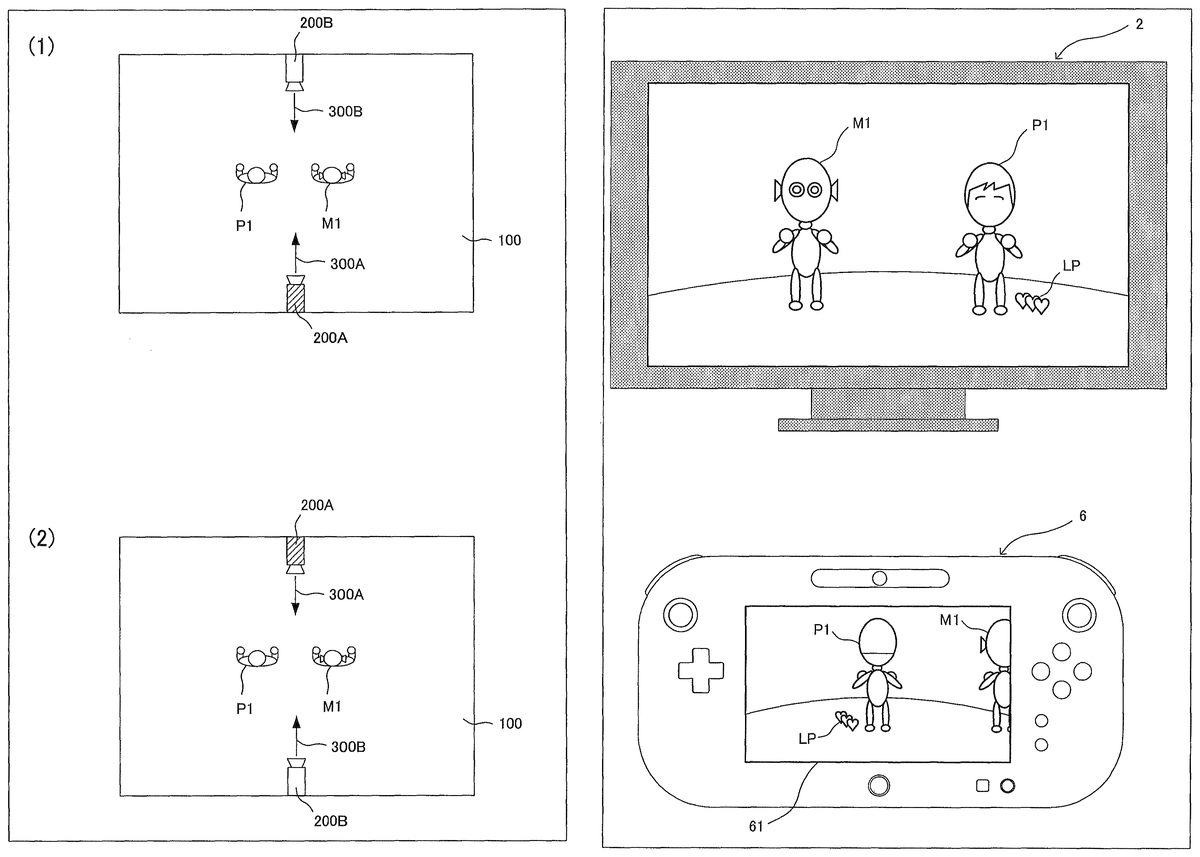
As shown in part (1) ofFIG. 6, a player object P1representing a player character and a sample object M1representing a sample character are placed in a virtual space100. Images of the virtual space100having those objects placed therein are taken by two virtual cameras200A and200B placed so as to face each other (so as to have imaging directions opposite to each other). Specifically, as an initial setting, the virtual camera200A is placed such that an imaging direction300A thereof is to take an image of the player object P1from the back thereof, and the virtual camera200B is placed such that an imaging direction300B thereof is to take an image of the player object P1from the front thereof. Then, an image of the virtual space100taken by the virtual camera200A is displayed, as a terminal game image, on the display screen of the terminal device6, and an image of the virtual space100taken by the virtual camera200B is displayed, as a monitor game image, on the display screen of the monitor2. Therefore, in the exemplary embodiment, the same virtual space is displayed on each of the display screen of the monitor2and the display screen of the terminal device6with different viewpoints (a viewpoint from the back and a viewpoint from the front).
Next, the game content of the rhythm game will be described. In the rhythm game of the exemplary embodiment, a rhythm action of the sample object M1is presented as a question. First, a player views the display screen (monitor game image) of the monitor2or the display screen (terminal game image) of the terminal device6to memorize a rhythm action (i.e., a question) of the sample object M1which acts in accordance with the tempo of “one, two, three” as sound to be outputted. Then, in the player's turn of operating the player object P1, the player operates the terminal device6to cause the player object P1to duplicate the rhythm action of the sample object M1in accordance with the tempo of “one, two, three”. Then, if both the timing and the action content of the rhythm action of the player object P1coincide with those of the rhythm action of the sample object M1, the rhythm action of the player object P1is determined as “very good”; if one of the timing and the action content is correct, the rhythm action is determined as “good”; and if none of them is correct, the rhythm action is determined as “bad”, i.e., an incorrect answer.
The rhythm game is composed of five stages in total, and ten questions (rhythm actions) are presented in each stage. While a player correctly answers each presented question, the player can progress to the next stage. Meanwhile, the life points of the player object P1decrease by one per one incorrect answer. If the life points decrease to zero, the game is over. It is noted that three points as the above life points are set before start of the game.
The action contents of the rhythm action performed by the sample object M1(that is, presented as a question) include four actions of “direction pose”, “rotation pose”, “action pose”, and “jump pose”.
When a player causes the player object P1to take a direction pose, the player gives an input in a constant direction (linearly) on the analog stick63. As a result, an operation target (in the exemplary embodiment, an arm of the player object P1) of the player object P1moves in a direction corresponding to the input direction. Here, the input direction of the analog stick63corresponds to a direction in which the operation target moves as seen from the back of the player object P1. Specifically, if a player gives an input leftward and linearly by tilting leftward the analog stick63, the player object P1takes a direction pose by moving its arm leftward as seen from the back. The movement of the right arm of the player object P1is set to be operable by the analog stick63B which is operated with the right hand of a player, and the movement of the left arm of the player object P1is set to be operable by the analog stick63A which is operated with the left hand of a player. Therefore, when a player performs an operation based on a viewpoint seeing the player object P1from the back, the player can easily and intuitively recognize the correspondence of direction and it is easy to cause the player object P1to do an intended rhythm action.
When a player causes the player object P1to take a rotation pose, the player gives an input (in a curved manner) by rotating the analog stick63. As a result, an arm of the player object P1moves so as to rotate in a direction corresponding to the inputted rotation direction. Here, as described above, the rotation direction inputted by the analog stick63corresponds to a direction in which an operation target rotates as seen from the back of the player object P1. For example, if a player gives a curved input of tilting the analog stick63A from the leftward direction to the upward direction, the player object P1takes a rotation pose of moving its left arm from the left to the above as seen from the back.
When a player causes the player object P1to take an action pose, the player rotates the terminal device6. As a result, the player object P1takes a pose of twisting its body in a direction corresponding to the inputted rotation direction. Here, the rotation direction inputted by the rotation of the terminal device6corresponds to a direction in which the player object P1rotates as seen from the back of the player object P1. For example, if a player rotates the terminal device6leftward, the player object P1takes an action pose of twisting its body leftward as seen from the back.
When a player causes the player object P1to take a jump pose, the player swings up the terminal device6. As a result, the player object P1takes a jump pose of jumping in a direction (upward) corresponding to the inputted swing-up direction.
As described above, when a player causes the player object P1to perform a rhythm action, operation based on a viewpoint seeing the player object P1from the back allows the direction correspondence to be intuitively recognized, thus providing easy operation.
Next, each stage of the rhythm game of the exemplary embodiment will be described. It is noted that in each stage, the tempo of “one, two, three” accelerates with progression of questions, and the difficulty level of questions increases with progression of stages.
In the first stage, as shown inFIG. 7, an image taken from a viewpoint seeing the front of the player object P1(hereinafter, referred to as a front viewpoint image) is displayed as a monitor game image on the display screen of the monitor2, and an image taken from a viewpoint seeing the back of the player object P1(hereinafter, referred to as a back viewpoint image) is displayed as a terminal game image on the display screen of the terminal device6. It is noted that a life point image LP which indicates the current life points of the player object P1is displayed near the feet of the player object P1.
In the first stage, since a back viewpoint image which allows intuitive recognition of direction correspondence is displayed on the terminal device6, a player can easily operate the player object P1by playing a game while viewing the display screen of the terminal device6, rather than viewing the display screen of the monitor2. Further, the display manner of the terminal device6is designed so as to facilitate the player's operation of the player object P1. Specifically, as shown in upper part ofFIG. 8, when the sample object M1performs a rhythm action (that is, when a question is presented), the display focuses the sample object M1, and as shown in lower part ofFIG. 8, when a player causes the player object P1to perform the rhythm action (that is, when a player answers the question), the display focuses the player object P1. By such focusing display, it becomes easy for a player to momentarily memorize the rhythm action because other information hardly comes into the player's field of view. Therefore, in the first stage, if a player plays a game viewing the display screen of the terminal device6, the player can easily operate the player object P1. On the other hand, the front viewpoint image displayed on the monitor2at this time functions as an observation image for other players or observers because the image area is large and the amount of displayed information is large. It is noted that a determination image AC which indicates “very good”, “good”, or “bad” in order to indicate whether or not an answer of a question is correct is displayed at predetermined positions (for example, at left upper portion) of the monitor game image and the terminal game image.
In the second stage, placements of the virtual camera200A and the virtual camera200B are replaced with each other. Specifically, as shown in part (2) ofFIG. 6, the virtual camera200A is placed such that the imaging direction300A thereof is to take an image of the player object P1from the front thereof, and the virtual camera200B is placed such that the imaging direction300B thereof is to take an image of the player object P1from the back thereof. Therefore, as shown inFIG. 9, a back viewpoint image is displayed on the display screen of the monitor2and a front viewpoint image is displayed on the display screen of the terminal device6. Therefore, if a player plays a game viewing the monitor2displaying a back viewpoint image which allows intuitive recognition of direction correspondence, the player can easily operate the player object P1. However, the monitor2does not perform the above-described focusing display unlike the terminal device6, and the amount of information displayed on the monitor2is larger than that of the terminal device6. Therefore, another object M2is also displayed, so that other information unnecessary for a player comes into the field of view. Thus, the second stage is higher in difficulty level than the first stage.
In the third stage, placements of the virtual camera200A and the virtual camera200B are replaced with each other again, so that a back viewpoint image is displayed on the monitor2and a front viewpoint image is displayed on the terminal device6. Therefore, basically, a player plays a game based on a back viewpoint, to operate the player object P1while viewing the terminal device6displaying a back viewpoint image which allows intuitive recognition of direction correspondence. However, in the third stage, in accordance with the number of times of the player's miss (incorrect answer), the play style is changed for a predetermined number of (zero to two) questions of ten question so as to cause a player to play a game based on a front viewpoint, to operate the player object P1while viewing the front viewpoint image displayed on the monitor2.
If the number of times of miss is zero, since the player has a high play skill and the life points are sufficient, a hindering event which changes the play style to cause the player to play based on a front viewpoint occurs for consecutive two questions of ten questions. Specifically, as shown in lower part ofFIG. 10, before a predetermined question (for example, the third question) is presented, a hindering event occurs in which a shielding object IM which is an image for hiding at least the sample object M1is displayed on the display screen of the terminal device6. As a result, the player cannot perform game operation by viewing the terminal device6displaying the back viewpoint image, and is compelled to perform game operation by viewing the monitor2. Here, in a front viewpoint image, since an input direction by a player does not apparently coincide with the direction of movement of the displayed player object P1, direction correspondence cannot be intuitively recognized. Specifically, when a player operates the analog stick63A which is operated with the left hand, an arm, of the player object P1, on the right as seen from the front (that is, the left arm) moves, and when a player operates the analog stick63B which is operated with the right hand, an arm, of the character object P1, on the left as seen from the front (that is, the right arm) moves. If a player tilts the analog stick63B leftward to give an input leftward and linearly, the player object P1takes a direction pose of moving its arm rightward as seen from the front. In the middle of questions, since the play style is switched from the back viewpoint play to the front viewpoint play, a player is compelled to abruptly cope with reverse of operation, and therefore, it is difficult to cause the player object P1to perform a desired action. Thus, the third stage is higher in difficulty level than the first stage and the second stage.
If the number of times of miss is one, since the player has a moderate play skill and there are some life points left, a hindering event occurs for one question of ten questions. Thus, the third stage is slightly higher in difficulty level than the first stage and the second stage.
If the number of times of miss is two, since the player has a low play skill and the life points are not sufficient, a hindering event does not occur. Therefore, in the third stage, the player can play a game based on a back viewpoint while viewing a back viewpoint image displayed on the display screen of the terminal device6, as in the first stage.
As described above, in the third stage, a hindering event occurs zero to two times in accordance with the number of times of miss, thereby enabling setting of difficulty level in accordance with the skill level of a player. Thus, even players having different skill levels can enjoy the same game together. In addition, for a player having a moderate or higher play skill, since the game style is changed in the middle of the game in the third stage, it is possible to enjoy game operation full of variety while alternately viewing the two display screens of the monitor2and the terminal device6in the middle of the game.
It is noted that even if the number of times of miss is zero before start of the third stage, there is a possibility that the number of times of miss becomes two because a player might miss by the time just before occurrence of the hindering event. In such a case, it is not appropriate to cause a hindering event which compels the player to do front viewpoint play with a high difficulty level, in spite of insufficiency of life points. Therefore, whether or not to cause a hindering event is determined again based on the number of times of miss just before occurrence of the hindering event.
In the fourth stage and the fifth stage, as in the third stage, the number of times of occurrence of a hindering event is determined based on the cumulative number of times of miss before start of the stage, and whether or not to actually cause the hindering event is determined based on the cumulative number of times of miss just before occurrence of the hindering event.
(Game Processing)
Next, with reference toFIGS. 11 to 14, the operation of the game system1for realizing the above game will be described in detail.
FIG. 11shows an example of various kinds of data stored in the external main memory12of the game apparatus body5when the above game is executed.
A game program D1is a program for causing the CPU10of the game apparatus body5to execute game processing for realizing the above game. The game program D1is, for example, loaded from the optical disc4into the external main memory12.
Question data D2is data of rhythm action presented in the rhythm game. The data of rhythm action includes a timing (“one”, “two”, or “three”), and a pose action corresponding to the timing.
Terminal operation data D3is operation data periodically transmitted from the terminal device6. As previously described, the terminal operation data D3includes stick data, velocity data, acceleration data, and the like.
Miss count data D4is data indicating the number of times a player has missed in a game (miss count value), and is updated by being incremented by one every time a player misses.
Stage data D5is numeral data indicating the stage number of the current game, and is incremented every time a player proceeds to the next stage.
Question number data D6is numeral data indicating the current question number in a stage, and is incremented every time one question is presented.
Life point data D7is numeral data indicating a life point value of the player object P1. The data is set at 3 as an initial value and is updated by being decremented by one every time a player misses.
Other data D8includes various pieces of data for game processing, such as data of the current placement of a virtual camera and image data of a player character and the like.
Next, with reference to flowcharts shown inFIGS. 12 to 14, the flow of game processing executed by the CPU10of the game apparatus body5based on the game program D1will be described. It is noted that the game processing in the case where a series of rhythm games from the first stage to the fifth stage (final stage) are executed will be described below, and the description of the other processing is omitted.
When execution of the game program D1is started, first, in step S11inFIG. 12, the CPU10performs initial setting for the virtual cameras200A and200B and the like. Specifically, the CPU10places the virtual camera200A and the virtual camera200B in the virtual space100as shown in part (1) ofFIG. 6. In addition, the CPU10clears the miss count data D4in the external main memory12(sets the miss count value at “0”), sets the stage data D5at a value “1” indicating the first stage, and sets the question number data D6at a value “1” indicating the first question. Then, the process proceeds to step S12.
In step S12, the CPU10performs question presentation and matching processing shown inFIG. 14.
In step S100inFIG. 14, the CPU10executes question presentation of the current stage. Specifically, the CPU10reads a predetermined rhythm action from the question data D2stored in the external main memory12, and controls the sample object M1based on the rhythm action. Then, the CPU10generates a terminal game image taken by the virtual camera200A and a monitor game image taken by the virtual camera200B. The generated monitor game image is outputted from the game apparatus body5to the monitor2, to be displayed on the display screen of the monitor2. The generated terminal game image is outputted from the game apparatus body5to the terminal device6, to be displayed on the display screen of the terminal device6. It is noted that a part or the entirety of the generation processing of the monitor game image and the terminal game image may be performed by the GPU32in accordance with an instruction from the CPU10. Then, the process proceeds to step S110.
In step S110, the CPU10acquires the terminal apparatus operation data D3from the terminal device6. Then, the process proceeds to step S120.
In step S120, the CPU10detects an input direction based on the terminal apparatus operation data D3, and controls the character object P1based on the detected input direction. Specifically, the CPU10detects a linear or curved input direction on the analog stick63, based on the stick data of the terminal apparatus operation data D3. In addition, the CPU10detects a rotation direction of the terminal device6, based on the angular velocity data of the terminal apparatus operation data D3. In addition, the CPU10detects the swing-up direction of the terminal device6, based on the acceleration data of the terminal apparatus operation data D3. It is noted that when the terminal device6is swung up, variation in the angular velocity data can also be detected. Therefore, the CPU10may determine that the terminal device6is rotating, on the condition that the angular velocity exceeds a predetermined threshold value. Then, the CPU10controls the player object P1, based on the detected input direction. Specifically, the CPU10causes the player object P1to take a direction pose based on a linear input direction of the analog stick63, causes the player object P1to take a rotation pose based on a curved input direction of the analog stick63, causes the player object P1to take an action pose based on a rotation direction of the terminal device6, and causes the player object P1to take a jump pose based on a swing-up direction of the terminal device6.
Then, the CPU10generates a terminal game image taken by the virtual camera200A and a monitor game image taken by the virtual camera200B. The generated monitor game image is outputted from the game apparatus body5to the monitor2, to be displayed on the display screen of the monitor2. The generated terminal game image is outputted from the game apparatus body5to the terminal device6, to be displayed on the display screen of the terminal device6. In addition, the CPU10updates the question number data D6by incrementing its value. Then, the process proceeds to step S130.
In step S130, regarding the action (rhythm action) of the player object P1controlled based on an input (input direction) by a player, the CPU10determines whether or not both the timing and the content of the action coincide with those of the rhythm action of the sample object M1. If the determination result is YES, the process proceeds to step S140, and if the determination result is NO, the process proceeds to step S150.
In step S140, the CPU10displays an image indicating “very good” as the determination image AC. Specifically, the CPU10displays the determination image indicating “very good” at predetermined positions on the monitor game image and the terminal game image. Then, the question presentation and the matching processing are finished to return to the subsequent process.
In step S150, regarding the action (rhythm action) of the player object P1controlled based on an input (input direction) by a player, the CPU10determines whether or not one of the timing and the content of the action coincides with that of the rhythm action of the sample object M1. If the determination result is YES, the process proceeds to step S160, and if the determination result is NO (that is, none of the timing and the operation coincides with the rhythm action), the process proceeds to step S170.
In step S160, the CPU10displays an image indicating “good” as the determination image AC. Specifically, the CPU10displays the determination image indicating “good” at predetermined positions on the monitor game image and the terminal game image. Then, the question presentation and the matching processing are finished to return to the subsequent process.
In step S170, the CPU10displays an image indicating “bad” as the determination image AC. Specifically, the CPU10displays the determination image indicating “bad” at predetermined positions (for example, left upper portion) on the monitor game image and the terminal game image. Then, the process proceeds to step S180.
In step S180, the CPU10updates the miss count data D4by incrementing the miss count value by one. In addition, the CPU10updates the life point data D7by decrementing the life point value by one, changes the life point image LP which indicates the life points, and displays the life point image LP at predetermined positions (for example, near the feet of the player object P1) on the monitor game image and the terminal game image. Then, the question presentation and the matching processing are finished to return to the subsequent process.
InFIG. 12, in step S13, the CPU10determines whether or not the current life point value is zero, by referring to the life point data D7. If the determination result is YES, the process proceeds to step S14, and if the determination result is NO, the process proceeds to step S15.
In step S14, the CPU10performs game over processing, to finish the game processing. Specifically, the CPU10displays a game over image indicating that the game is over, at predetermined positions on the monitor game image and the terminal game image, to finish the game processing.
In step S15, the CPU10determines whether or not the questions in the current stage have been finished. Specifically, the CPU10determines whether or not the final question (the tenth question) in the current stage has been presented (that is, determines whether or not the question number data D6has become “11” by being incremented after the tenth question has been presented). If the determination result is YES, the process proceeds to step S16in order to progress to the next stage, and if the determination result is NO, the process proceeds to step S12in order to progress to the next question in the current stage.
In step S16, the CPU10changes the setting of the virtual cameras200A and200B and the like. Specifically, the CPU10changes the placements of the virtual camera200A and the virtual camera200B as shown in part (2) ofFIG. 6(that is, replaces the placements of the virtual camera200A and the virtual camera200B with each other). In addition, the CPU10updates the stage data D5by incrementing its value, and sets the question number data D6at a value “1” indicating the first question. Then, the process proceeds to step S17.
In step S17, the CPU10determines whether or not the current stage is the second stage. Specifically, the CPU10determines whether or not the stage data D5is “2”. If the determination result is YES, the process proceeds to step S18inFIG. 13in order to progress to the third stage, and if the determination result is NO (that is, the current stage is the first stage), the process proceeds to step S12.
InFIG. 13, in step S18, the CPU10determines whether or not the current miss count value is zero, by referring to the miss count data D4. If the determination result is YES, the process proceeds to step S19, and if the determination result is NO, the process proceeds to step S26.
In step S19, the CPU10determines whether or not it is time to cause a hindering event. Specifically, by referring to the question number data D6, the CPU10determines whether or not the value coincides with a set question number (for example, the third question). It is noted that the question number to cause a hindering event may be stored in advance in the external main memory12or may be randomly determined. If the determination result is YES, the process proceeds to step S21, and if the determination result is NO, the process proceeds to step S20.
In step S20, the CPU10performs question presentation and matching processing. It is noted that the processing of step S20is the same as in the question presentation and matching processing described in step S12, and the detailed description thereof is omitted. Then, the process proceeds to step S18.
In step S21, the CPU10executes the first hindering event. Specifically, the CPU10displays the shielding object IM at a predetermined position (at least at a position hiding the sample object M1) on the terminal game image. Then, the process proceeds to step S22.
In step S22, the CPU10performs question presentation and matching processing. It is noted that the processing of step S22is the same as in the question presentation and matching processing described in step S12, and the detailed description thereof is omitted. Then, the process proceeds to step S23.
In step S23, the CPU10executes the second hindering event. Specifically, the CPU10successively displays the shielding image IM displayed at the predetermined position on the terminal game image. Then, the process proceeds to step S24.
In step S24, the CPU10performs question presentation and matching processing. It is noted that the processing of step S24is the same as in the question presentation and matching processing described in step S12, and the detailed description thereof is omitted. Then, the process proceeds to step S25.
In step S25, the CPU10finishes the hindering event. Specifically, the CPU10eliminates the display of the shielding image IM displayed at the predetermined position on the terminal game image. Then, the process proceeds to step S30.
It is noted that by execution of the above process from step S21to step S25, a hindering event occurs in consecutive two questions from a question number (for example, the third question) set in advance, of the ten questions.
In step S26, the CPU10determines whether or not the current miss count value is one, by referring to the miss count data D4. If the determination result is YES, the process proceeds to step S27, and if the determination result is NO (that is, the miss count value is two), the process proceeds to step S31.
In step S27, the CPU10determines whether or not it is time to cause a hindering event. Specifically, by referring to the question number data D6, the CPU10determines whether or not the value coincides with a set question number (for example, the fifth question). If the determination result is YES, the process proceeds to step S28, and if the determination result is NO, the process proceeds to step S20.
In step S28, the CPU10executes the first hindering event. It is noted that the processing of step S28is the same as the processing of step S21, and the detailed description thereof is omitted. Then, the process proceeds to step S29.
In step S29, the CPU10performs question presentation and matching processing. It is noted that the processing of step S29is the same as in the question presentation and matching processing described in step S12, and the detailed description thereof is omitted. Then, the process proceeds to step S25.
It is noted that by execution of the above process of step S28, step S29, and step S25, a hindering event occurs in a question number (for example, the fifth question) set in advance, of the ten questions.
In step S30, the CPU10determines whether or not the questions in the current stage have been finished. It is noted that the processing of step S30is the same as the processing of step S15, and the detailed description thereof is omitted. If the determination result is YES, the process proceeds to step S34, and if the determination result is NO, the process proceeds to step S31.
In step S31, the CPU10performs question presentation and matching processing. It is noted that the processing of step S31is the same as in the question presentation and matching processing described in step S12, and the detailed description thereof is omitted. Then, the process proceeds to step S32.
In step S32, the CPU10determines whether or not the current life point value is zero, by referring to the life point data D7. If the determination result is YES, the process proceeds to step S14(seeFIG. 12), and if the determination result is NO, the process proceeds to step S33.
In step S33, the CPU10determines whether or not the questions in the current stage have been finished. It is noted that the processing of step S33is the same as the processing of step S15, and the detailed description thereof is omitted. If the determination result is YES, the process proceeds to step S34, and if the determination result is NO, the process proceeds to step S31.
In step S34, the CPU10determines whether or not the current stage is the final stage (the fifth stage). Specifically, the CPU10determines whether or not the stage data D5is “5”. If the determination result is YES, the process proceeds to step S35, and if the determination result is NO, the process proceeds to step S36.
In step S35, the CPU10performs game completion processing, to finish the game processing. Specifically, the CPU10displays a game completion image indicating that the game has been completed, at predetermined positions on the monitor game image and the terminal game image, to finish the game processing.
In step S36, the CPU10determines whether or not the current miss count value is two, by referring to the miss count data D4. If the determination result is YES, the process proceeds to step S38, and if the determination result is NO, the process proceeds to step S37.
In step S37, the CPU10performs setting updating processing. Specifically, the CPU10updates the stage data D5by incrementing its value, and sets the question number data D6at a value “1” indicating the first question. Then, the process proceeds to step S18.
In step S38, the CPU10changes the setting of the virtual cameras200A and200B and the like. Specifically, the CPU10replaces the current placements of the virtual camera200A and the virtual camera200B with each other. In addition, the CPU10updates the stage data D5by incrementing its value, and sets the question number data D6at a value “1” indicating the first question. Then, the process proceeds to step S31.
As described above, according to the exemplary embodiment, first, the viewpoint of an image displayed on the monitor2and the viewpoint of an image displayed on the terminal device6(that is, a viewpoint from the back and a viewpoint from the front) are replaced with each other between stages (for example, between the first stage and the second stage), whereby the display screen displaying a back viewpoint image which facilitates the player's game operation is switched between the monitor2and the terminal device6. As a result, a player changes the play style by changing the display screen to view for performing game operation between stages. In addition, for a player having a moderate or higher skill, a hindering event occurs in the middle of the game (for example, at a predetermined question in the third stage), whereby the play style for the game is forcibly changed. Thus, game operation full of variety can be realized. In addition, the number of times of occurrence of a hindering event is controlled in accordance with the number of times (miss count value) a player has missed until the current stage, whereby the difficulty level can be set in accordance with the skill level of a player, and even players having different skill levels can enjoy the same game.
It is noted that the above exemplary embodiment is merely an example, and the exemplary embodiments are not limited thereto at all.
In the above exemplary embodiment, if the miss count value is zero, a hindering event occurs in consecutive two questions, for example. However, a hindering event may occur in two questions that are not consecutive. In addition, the number of questions where a hindering event occurs is not limited to two.
In the above exemplary embodiment, the placements of the virtual camera200A and the virtual camera200B are replaced with each other, whereby a back viewpoint image and a front viewpoint image are switched. However, instead of replacing the placements of the virtual camera200A and the virtual camera200B, the orientations of the player object P1and the sample object M1may be changed by 180 degrees. Alternatively, instead of replacing the placements of the virtual camera200A and the virtual camera200B, the output destinations of an image taken by the virtual camera200A (back viewpoint image) and an image taken by the virtual camera200B (front viewpoint image) may be switched between the monitor2and the terminal device6.
In the above exemplary embodiment, the plurality of processes shown inFIGS. 12 to 14are executed by one computer (the CPU10). However, in another exemplary embodiment, these processes may be shared by a plurality of computers. In still another exemplary embodiment, some of these processes may be realized by means of a hardware circuit.
In the above exemplary embodiment, the plurality of processes shown inFIGS. 12 to 14are executed by one information processing apparatus (the game apparatus body5). However, in another exemplary embodiment, these processes may be shared by a plurality of information processing apparatuses (for example, the game apparatus body5and a server apparatus).
In the above exemplary embodiment, the game program D1is provided from the optical disc4to the game apparatus body5. However, in another exemplary embodiment, the game program D1may be provided from any computer-readable storage medium (for example, CD-ROM, semiconductor memory, or the like) to the game apparatus body5. In still another exemplary embodiment, the game program D1may be stored in advance in a nonvolatile memory (the ROM/RTC13or the flash memory17) in the game apparatus body5. In still another exemplary embodiment, the game program D1may be transmitted from another information processing apparatus (game apparatus or server apparatus) to the game apparatus body5.
The systems, devices and apparatuses described herein may include one or more processors, which may be located in one place or distributed in a variety of places communicating via one or more networks. Such processor(s) can, for example, use conventional 3D graphics transformations, virtual camera and other techniques to provide appropriate images for display. By way of example and without limitation, the processors can be any of: a processor that is part of or is a separate component co-located with the stationary display and which communicates remotely (e.g., wirelessly) with the movable display; or a processor that is part of or is a separate component co-located with the movable display and communicates remotely (e.g., wirelessly) with the stationary display or associated equipment; or a distributed processing arrangement some of which is contained within the movable display housing and some of which is co-located with the stationary display, the distributed portions communicating together via a connection such as a wireless or wired network; or a processor(s) located remotely (e.g., in the cloud) from both the stationary and movable displays and communicating with each of them via one or more network connections; or any combination or variation of the above.
The processors can be implemented using one or more general-purpose processors, one or more specialized graphics processors, or combinations of these. These may be supplemented by specifically-designed ASICs (application specific integrated circuits) and/or logic circuitry. In the case of a distributed processor architecture or arrangement, appropriate data exchange and transmission protocols are used to provide low latency and maintain interactivity, as will be understood by those skilled in the art.
Similarly, program instructions, data and other information for implementing the systems and methods described herein may be stored in one or more on-board and/or removable memory devices. Multiple memory devices may be part of the same device or different devices, which are co-located or remotely located with respect to each other.
While the exemplary embodiments have been described in detail, the foregoing description is in all aspects illustrative and not restrictive. It is understood that numerous other modifications and variations can be devised.
Claims
- A game system comprising: an operation device having an operation section and a first display section;an input direction detector configured to detect an input direction that is designated, based on input to the operation section;an object controller configured to, in accordance with the input direction, perform control such that an operation target object in a virtual space moves in a predetermined direction in the virtual space associated with the input direction;a first virtual camera setter configured to set a first virtual camera for taking the operation target object in a first direction;a second virtual camera setter configured to set a second virtual camera for taking the operation target object in a second direction which is substantially opposite to the first direction;a first image generator configured to generate a first game screen, based on the first virtual camera;a second image generator configured to generate a second game screen, based on the second virtual camera;a first image transmitter configured to transmit the first game screen to the operation device;a second image outputter configured to output the second game screen to a second display device which is a device separate from the first display section;and a viewpoint switcher configured to, at a predetermined timing based on game processing, in the virtual space, replace a direction in which the first virtual camera is set as seen from the operation target object and a direction in which the second virtual camera is set as seen from the operation target object with each other;the first image generator further generates an image shielding at least a part of an image of the virtual space taken by the first virtual camera, at a predetermined timing based on a game processing.
- The game system according to claim 1 , wherein the viewpoint switcher replaces, in accordance with game progress, a direction in which the first virtual camera is set as seen from the operation target object and a direction in which the second virtual camera is set as seen from the operation target object with each other.
- The game system according to claim 1 , wherein the operation target object is at least a part of a player object, the first virtual camera setter sets the first virtual camera such that the first virtual camera takes the operation target object from a viewpoint seeing the back of the player object, the second virtual camera setter sets the second virtual camera such that the second virtual camera takes the operation target object from a viewpoint seeing the front of the player object, the object controller performs control such that the input direction is the same as a movement direction of the at least part of the player object as seen from the back, and the viewpoint switcher replaces the viewpoint seeing the back and the viewpoint seeing the front with each other, or reverses a direction of the player object.
- The game system according to claim 3 , wherein the operation section includes a stick section, the input direction detector detects a stick input direction, based on an input to the stick section, and the object controller performs control such that the stick input direction apparently coincides with a movement direction of the at least part of the player object as seen from the back.
- The game system according to claim 4 , wherein the stick section includes a left stick section provided so as to be operable by the left hand of a player, and a right stick section provided so as to be operable by the right hand of a player, the operation target object includes a left object which is a part of the player object and is positioned on the left as seen from the back, and a right object which is a part of the player object and is positioned on the right as seen from the back, the input direction detector detects a left stick input direction, based on an input to the left stick section, and detects a right stick input direction, based on an input to the right stick section, and the object contoller performs control such that the left stick input direction apparently coincides with a movement direction of the left object as seen from the back, and performs control such that the right stick input direction apparently coincides with a movement direction of the right object as seen from the back.
- The game system according to claim 1 , further comprising a game progress controller configured to progress a game when movement of the operation target object controlled by the object controller is the same as predetermined movement that is set.
- The game system according to claim 6 , further comprising: a timing determiner configured to determine whether or not a timing of an input to the operation section coincides with a predetermined timing that is set;and a movement direction determiner configured to determine whether or not the input direction detected by the input direction detector is the same as a predetermined direction that is set, wherein the game progress controller progresses a game when at least one of a determination result by the timing determiner and a determination result by the movement direction determiner is positive.
- The game system according to claim 1 , wherein the operation section includes a gyro sensor, and the input direction detector detects the input direction that is designated, based on the gyro sensor.
- A game processing method comprising: detecting an input direction that is designated, based on input to an operation section of an operation device;performing control, in accordance with the input direction, such that an operation target object in a virtual space moves in a predetermined direction in the virtual space associated with the input direction;setting a first virtual camera for taking the operation target object in a first direction;setting a second virtual camera for taking the operation target object in a second direction which is substantially opposite to the first direction;generating a first game screen, based on the first virtual camera;generating a second game screen, based on the second virtual camera;transmitting the first game screen to the operation device;outputting the second game screen to a second display device which is a device separate from a first display section of the operation device;replacing, at a predetermined timing based on game processing, in the virtual space, a direction in which the first virtual camera is set as seen from the operation target object and a direction in which the second virtual camera is set as seen from the operation target object with each other;and generating an in at least a part of an image of the virtual space taken by the first virtual camera, at a predetermined timing based on game processing.
- The game processing method according to claim 9 , wherein the replacing step replaces, in accordance with game progress, a direction in which the first virtual camera is set as seen from the operation target object and a direction in which the second virtual camera is set as seen from the operation target object with each other.
- The game processing method according to claim 9 , wherein the operation target object is at least a part of a player object, the first virtual camera setting step sets the first virtual camera such that the first virtual camera takes the operation target object from a viewpoint seeing the back of the player object, the second virtual camera setting step sets the second virtual camera such that the second virtual camera takes the operation target object from a viewpoint seeing the front of the player object, the object control step performs control such that the input direction is the same as a movement direction of the at least part of the player object as seen from the back, and the replacing step replaces the viewpoint seeing the back and the viewpoint seeing the front with each other, or reverses a direction of the player object.
- The game processing method according to claim 11 , wherein the operation section includes a stick section, the input direction detection step detects a stick input direction, based on an input to the stick section, and the object control step performs control such that the stick input direction apparently coincides with a movement direction of the at least part of the player object as seen from the back.
- The game processing method according to claim 12 , wherein the stick section includes a left stick section provided so as to be operable by the left hand of a player, and a right stick section provided so as to be operable by the right hand of a player, the operation target object includes a left object which is a part of the player object and is positioned on the left as seen from the back, and a right object which is a part of the player object and is positioned on the right as seen from the back, the input direction detection step detects a left stick input direction, based on an input to the left stick section, and detects a right stick input direction, based on an input to the right stick section, and the object control step performs control such that the left stick input direction apparently coincides with a movement direction of the left object as seen from the back, and performs control such that the right stick input direction apparently coincides with a movement direction of the right object as seen from the back.
- The game processing method according to claim 9 , further comprising progressing a game when movement of the operation target object controlled in the object control step is the same as predetermined movement that is set.
- The game processing method according to claim 14 , further comprising: determining whether or not a timing of an input to the operation section coincides with a predetermined timing that is set;and determining whether or not the input direction detected in the input direction detection step is the same as a predetermined direction that is set, wherein the game progress includes progressing a game when at least one of a determination result of the timing determination step and a determination result of the direction determination step is positive.
- The game processing method according to claim 9 , wherein the operation section includes a gyro sensor, and the input direction detection step detects the input direction that is designated, based on the gyro sensor.
- A game apparatus comprising: an operation device having an operation section and a first display section;a processing system, comprising a computer processor, the processing system being configured at least to execute: an input direction detection to detect an input direction that is designated, based on input to the operation section;an object control to, in accordance with the input direction, perform control such that an operation target object in a virtual space moves in a predetermined direction in the virtual space associated with the input direction;a first virtual camera setting to set a first virtual camera for taking the operation target object in a first direction;a second virtual camera setting to set a second virtual camera for taking the operation target object in a second direction which is substantially opposite to the first direction;a first image generation to generate a first game screen, based on the first virtual camera;a second image generation to generate a second game screen, based on the second virtual camera;a first image transmission to transmit the first game screen to the operation device;a second image output to output the second game screen to a second display device which is a device separate from the first display section;a viewpoint switching to, at a predetermined timing based on game processing, in the virtual space, replace a direction in which the first virtual camera is set as seen from the operation target object and a direction in which the second virtual camera is set as seen from the operation target object with each other;and generation of an image shielding at least apart of an image of the virtual space taken by the first virtual camera, at predetermined timing based on game processing.
- A non-transitory computer-readable storage medium having stored therein a game program which is executed by a computer of a game system that includes an operation device having an operation section and a first display section, the game program causing the computer to provide functionality comprising: an input direction detection to detect an input direction that is designated, based on input to the operation section;an object control to, in accordance with the input direction, perform control such that an operation target object in a virtual space moves in a predetermined direction in the virtual space associated with the input direction;a first virtual camera setting to set a first virtual camera for taking the operation target object in a first direction;a second virtual camera setting to set a second virtual camera for taking the operation target object in a second direction which is substantially opposite to the first direction;a first image generation to generate a first game screen, based on the first virtual camera;a second image generation to generate a second game screen, based on the second virtual camera;a first image transmission to transmit the first game screen to the operation device;a second image output to output the second game screen to a second display device which is a device separate from the first display section;a viewpoint switching to, at a predetermined timing based on game processing, in the virtual space, replace a direction in which the first virtual camera is set as seen from the operation target object and a direction in which the second virtual camera is set as seen from the operation target object with each other;and generation of an shielding at least a part of an image of the virtual space taken by the first virtual camera, at a predetermined timing based on game processing.
Disclaimer: Data collected from the USPTO and may be malformed, incomplete, and/or otherwise inaccurate.