U.S. Pat. No. 9,180,364
GAME CONTROLLER ADAPTED FOR USE BY MOBILITY IMPAIRED PERSONS
AssigneeLP ACCESSIBLE TECHNOLOGIES, LLC
Issue DateApril 12, 2012
Illustrative Figure
Abstract
A primary game controller for use by a mobility impaired person by interfacing with a peripheral controller that allows the user to input precise movements needed for certain game functions. The peripheral controller may be operated by a part of a user's body in which the user has sufficient motor control, while the primary game controller may provide control inputs that require lesser motor control to operate. A control unit on the game controller may transmit control signals from the game controller and the peripheral controller, or may exclusively use the peripheral controller as the input for certain game functions. The game controller may be sized to be able to rest on a user's lap and to provide bigger control inputs.
Description
DETAILED DESCRIPTION FIG. 1illustrates one embodiment of a game controller100adapted for use by a mobility impaired user. The large surface of the game controller100relieves a user from having to hold the controller with just his or her hands, and instead allows the controller100to rest on the user's lap. Because the surface is large enough for the user to rest his or her hands on the controller, the user's arms or hands are less likely to tire during long periods of game play. A curved region105on the back side of the controller may have a contour that receives or hugs the abdomen of the user. The curved region105may create a fit around the user so that the controller100is more stable and does not shift sideways (i.e., in the lateral direction) during game play, allowing the user to use the controller100in a sitting or semi-reclined position. The large surface of the game controller100may also allow bigger control inputs, such as buttons, to be installed on the controller100. A control input refers to any device that may receive a user input and generate a control signal. Examples of a control input include, but are not limited to, buttons, joysticks, triggers, steering wheels, switches, paddles, or any combination thereof. It may be more convenient for a mobility impaired user to press individual buttons that have larger surface areas or that are spaced farther apart. It may be more convenient for a user to manipulate a joystick, for example, that is big or tall enough to be manipulated or pushed by a user's hand. The game controller is not limited to the size shown in these embodiments, but may take any size that allows the controller's surface to receive control inputs that are large enough to be easily reached by a user with a mobility ...
DETAILED DESCRIPTION
FIG. 1illustrates one embodiment of a game controller100adapted for use by a mobility impaired user. The large surface of the game controller100relieves a user from having to hold the controller with just his or her hands, and instead allows the controller100to rest on the user's lap. Because the surface is large enough for the user to rest his or her hands on the controller, the user's arms or hands are less likely to tire during long periods of game play. A curved region105on the back side of the controller may have a contour that receives or hugs the abdomen of the user. The curved region105may create a fit around the user so that the controller100is more stable and does not shift sideways (i.e., in the lateral direction) during game play, allowing the user to use the controller100in a sitting or semi-reclined position.
The large surface of the game controller100may also allow bigger control inputs, such as buttons, to be installed on the controller100. A control input refers to any device that may receive a user input and generate a control signal. Examples of a control input include, but are not limited to, buttons, joysticks, triggers, steering wheels, switches, paddles, or any combination thereof. It may be more convenient for a mobility impaired user to press individual buttons that have larger surface areas or that are spaced farther apart. It may be more convenient for a user to manipulate a joystick, for example, that is big or tall enough to be manipulated or pushed by a user's hand.
The game controller is not limited to the size shown in these embodiments, but may take any size that allows the controller's surface to receive control inputs that are large enough to be easily reached by a user with a mobility impairment. For example, the game controller100ofFIG. 1may be sized relative to the size of a wheelchair200. Some wheelchair manufacturers, for example, produce adult-sized wheelchairs with a standard seat width of 18 inches and child-sized wheelchairs with a standard seat width of 10 to 16 inches. For this example, the game controller100may be provided at two lateral widths, one sized to fit a user of a wheelchair with an 18 inch seat and one sized to fit a user of a wheelchair with a 10 to 16 inch seat. The lateral width of the game controller100may be based on other metrics of a wheelchair, such as a standard distance between arm rests. The lateral width of the game controller100may be based on metrics of other standards, such as ergonomic standards, furniture standards, building codes, or any combination thereof.
Control inputs such as a joystick110and buttons120,130of the game controller100are shown inFIG. 2AandFIG. 2B. The joystick110may receive a directional movement input, such as a push on the joystick that pivots it toward a direction in the plane of the controller surface, and may generate a control signal to move in a corresponding direction in the game.
The joystick110may output signals to the controller100through an electrical connector that is connected to a port150of the controller. For example, the joystick110may include a TRS connector, an Ethernet connector, a USB connector, a D-sub connector, or any combination thereof. The joystick's110connector may be plugged into the port150to transmit signals to the controller110. A port refers to any electrical component, such as a socket or jack, configured to receive insertion of an electrical connector. The port150may be part of a communication interface on the controller100. For example, the port150may be part of a general peripheral control input communication interface that accepts connectors from peripheral control inputs, such as a chin stick or motion sensor. The communication interface may accept a connector from the game controller's joystick110by treating it as a peripheral input.FIG. 2Ashows another port140that may also be part of the general peripheral control input communication interface.
The ports140,150in the communication interface may be dedicated to joysticks and similar control inputs. For example, in a game that may require two joystick control inputs, the two ports140and150may each be connected with a different joystick control input. A connector from joystick110, for example, may be plugged into port140or port150. A second joystick may be installed on the right side of the controller100. In that example, a user may need to use his or her right hand to simultaneously manipulate the joystick and hit buttons on the right side. Because the surface of the controller100may be large, with control inputs spaced far apart, a user may find it difficult to simultaneously reach a joystick and buttons on the controller. Alternatively, the second joystick control input may be a peripheral controller, such as a chin stick, that plugs into port140or150. Using a chin stick that plugs into the port140, for example, may free the right hand to hit buttons124on the controller100without needing to simultaneously reach for a joystick.
A user may choose the game function of a joystick control input by plugging it into either port140or150. For example, port150on the left side of the controller may be associated with an aiming function that may be controlled by a joystick, while port140on the right side may be associated with a movement function that may be controlled by another joystick. Plugging the joystick110connector into port150may assign it as the control input used to provide aiming commands to a game, while plugging the joystick110connector into port140may assign it as the control input used to provide movement commands to the game. The user may also choose the game function of a peripheral controller like a chin stick by plugging it into port140or150. For example, plugging a chin stick into port150may assign the chin stick to provide aiming commands to the game, while plugging the chin stick into port140may assign it to provide movement commands to the game.
By choosing where to plug the joystick110or a peripheral controller, a user may reconfigure the game function of the control inputs on the controller100and of the peripheral controller to adapt them to his or her mobility impairment. For example, a user with sufficient motor control in his or her left hand to provide aiming movements may assign the aiming function to joystick110, which is on the left side of the controller, by plugging the joystick's110connector to port150. A user with limited motor control in his or her left hand or in both hands may assign the aiming function to a chin stick by plugging a chin stick connector to port150. In that example, the user may use the joystick110for movement functions by plugging the joystick110into port140.
A user may also reconfigure the game function of control inputs to relieve a body part that is becoming fatigued. For example, a user whose left hand is tiring from constant aiming movements may rest his or her left hand by switching the control input for the aiming function to a peripheral controller like a chin stick. In that example, the user may unplug the left joystick110from port150, into which a connector from the chin stick may be plugged. The user may reconfigure the left joystick110as a control input for movement commands, which may be less tiring than aiming, by plugging the connector of the joystick110into port140. Alternatively, a user may use a second peripheral controller, such as a motion sensor attached to his or her leg, to control the movement function. In that example, a connector from the motion sensor may be plugged into port140. A user may use the two peripheral controllers to adapt the controller100and peripheral controllers to his or her mobility impairment. For example, a user with no motor control in his or her left hand, or a user who may be an amputee who lost his or her left arm, may not be able to use joystick110. In that example, the users may instead use a motion sensor or chin stick in place of the joystick110by plugging the motion sensor or chin stick into port150. The users may use a second peripheral controller by plugging it into port140.
In some embodiments, a user may reconfigure the game function of control inputs, like a joystick, on the controller without unplugging the joystick. For example, the joystick110may directly output signals to internal electrical connections that relay the signals to control logic inside the controller. Such internal electrical connections may be provided, for example, in a receptacle in which the joystick110is installed. In that embodiment, the joystick110may have no external connector. In that embodiment, the port150may still be dedicated to a joystick input, and plugging a peripheral controller into port150may switch a gaming function from the joystick110to the peripheral controller. For example,FIG. 2Cshows a block diagram of the game controller100and the peripheral control input communication interface. The port150inFIG. 2Cmay transmit control signals from a chin stick, for example, into a switch that then blocks the control signals from the joystick110and instead relay control signals from the chin stick. If no chin stick is plugged into port150, the switch may instead relay control signals from the joystick110. A user may choose to use a peripheral controller instead of the game controller joystick110by plugging the connector of the external joystick into port150.
The controller100may also provide switching inputs to reconfigure the gaming functions of control inputs and peripheral controllers. For example, the controller100may have a toggle switch or button that may assign a different function to the joystick110and a peripheral controller connected to the controller100. A joystick110previously used for aiming may be reassigned to a movement function, while a motion sensor used for movement may be reassigned to an aiming function. In that example, the peripheral controller and the joystick110may not need to be unplugged from a port. In that example, the joystick110may have no external connector to unplug.
The ports140or150may be located anywhere on the controller's100surface, and may be associated with different game functions. For example, port150may be associated with a movement function, and port140may be associated with an aiming function. The game functions associated with the ports may be preprogrammed, dynamically assigned, or any combination thereof. The controller may have more ports. For example, a user may wish to use the joystick110as well as a chin stick and motion sensor. The controller may have three, four, or more ports to accommodate a plurality of peripheral controllers. The controller may also include a wireless, receiver in a peripheral control input communication interface that establishes wireless data connections with a plurality of peripheral controllers.
The data connection between the peripheral control inputs and the peripheral control input communication interface may be a wired or a wireless connection. For example, a peripheral communication interface on the controller100may include a Bluetooth® wireless receiver to communicate with a motion sensor. A button on the controller100may be used to establish the wireless data connection with the motion sensor. If the user wished to switch the game function of the motion sensor to a chin stick, the same button or a different button on the controller may allow the user to terminate the wireless data connection with the motion sensor. The user may move the motion sensor out of wireless range or may disable the wireless function of the motion sensor. The user may then establish a wireless data connection with the chin stick.
FIG. 2Bshows a user interacting with the joystick110of the controller100. The joystick110may have ergonomic features such as a foam grip or curved recesses that fit around a user's fingers. The joystick110may be configured to pivot in any direction in the plane of the controller surface, or may simply pivot forward and backward with one degree of freedom. Other control inputs, such as triggers or buttons, may also be attached to the joystick110.
FIGS. 2A and 2Bshow controller buttons in a plurality of sizes. A first set120of larger buttons may be provided for movement or action inputs. Four of the buttons122, for example, may control movement in a forward, backward, left, and right directions, respectively, in a game's virtual environment. Another four buttons124of the set120may control actions for crawling, ducking, parrying, and shooting, respectively, in the game's virtual environment. A second set130of smaller buttons may be provided for higher-level game functions, such as starting, ending, or pausing a game. Because the buttons in the second set130are smaller, they may also be spaced farther apart for easier access. The game functions of the control signals generated by the buttons120,130may overlap with those of other control inputs. For example, both the joystick110and buttons122may control movement, or both the joystick110and buttons124may control shooting in the game environment. In that example, the control unit may transmit movement control signals from only the joystick or transmit shooting control signals from only the buttons124.
The functions of the buttons120,130may also be simplified. For example, four of the buttons124in the first set120may serve the same function. Rather than having to hit an individual button, a user may hit any combination of the four buttons124to generate, for example, a command to shoot, thrust, or throw a weapon in the game. The example of movement buttons122and action buttons124is also shown inFIG. 3A. InFIG. 3A, the A, B, X, Y buttons124may generate control signals for four separate functions in the game. Alternatively, the four buttons may generate control signals for the same function, so that a user may input an action command by hitting any combination of the A, B, X, Y buttons124.
FIG. 3Aalso shows a top view of the game controller100. The figure shows the curved region105that is recessed for the entire height of the controller body to fit the rear side of the controller against a user's abdomen, hip, or another region of the torso. The curve of the region105may resemble the middle of a crescent shape. The middle of a crescent shape may refer to any shallow, recessed curve that may fit the contour of the controller around a user's torso. The region105may also have a more general concave shape. The concave shape may approximate the contour of a user's torso with a more general curve or with straight lines. For example, the region105may use straight lines to create a recessed contour that appears like the top of a trapezoid.
By way of example, the recess105may have a fore-aft length between 2 inches and 24 inches, or between 3 inch and 14 inches, with a specific example of 10 inches. Curved regions that may fit the controller on a user's legs are shown inFIG. 3B, which extend preferably in the entire fore-aft direction of the controller100. The curved regions include a curved recess170and curved recess180may each be shaped to increase the surface contact area between the controller's110bottom surface and a user's legs. The increased surface contact area created by the curved recesses105,170,180may enhance the stability of the game controller100during game play. The extra contact makes the controller100less likely to shift sideways and less likely to slide off the user's lap during game play. The curved recesses170and180may also have a more general concave shape, such as with interconnected flat walls. By way of example, each of the curved recesses170,180may have a lateral width that is between 2 inches and 10 inches, or between 3 inches and 9 inches, with a specific example of 6 inches. Also by way of example, each of the curved recesses170,180may have a fore-aft length that is between 2 inches and 10 inches, or between 4 inches and 8 inches, with a specific example of 6 inches.
FIG. 3Cshows an embodiment with recesses172and182for receiving a user's legs. The recesses preferably extends in the fore-aft direction of the controller100. The recesses may increase the surface contact area between the controller and the user's legs or thighs so that the controller is less likely to shift sideways and less likely to slide off the user's lap during game play. The recesses172and182may also have a more general shape, such as with interconnected flat walls. By way of example, each of the curved recesses172,182may have a fore-aft depth that is between 2 inches and 11 inches, or between 4 inches and 8 inches, with a specific example of 6 inches. Also by way of example, each of the curved recesses172,182may have a lateral width that is between 2 inches and 11 inches, or between 4 inches and 9 inches, with a specific example of 8 inches
FIGS. 3A and 3Balso show example dimensions of the game controller. The controller100is not limited to the dimensions inFIG. 3AorFIG. 3Band may have dimensions in a plurality of other ranges. For example, the lateral width of the controller100may be adjusted to accommodate users of different sizes. By way of example, the recess105may have a lateral width between 5 and 24 inches, or between 6 and 17 inches, with a specific example of 16 inches.
The fore-aft length of the controller may be decreased from the 10 inches shown inFIG. 3Aor the height decreased from 2 inches to decrease the weight of the controller. The fore-aft length may also be increased to improve surface contact area with a user's legs. The height may also be increased to make the top surface of the controller110easier to reach. The joystick110may be made longer or shorter to adjust to users with different hand sizes, and smaller or larger buttons120,130may be used.
The control inputs on the controller110are not limited to those shown in these embodiments, but may include triggers, switches, steering wheels, trackballs, knobs, keys, touch screens, and touch pads. Virtual control inputs, such as virtual buttons or joysticks, may also be rendered on a touch screen.
The control inputs on the game controller110may be manipulated by a user's hands or other body parts. For example, a user may manipulate the joystick110with his or her elbow, or may place the controller110on the floor and manipulate the joystick110and buttons120,130with his or her feet. The user may also manipulate a peripheral controller with body parts like his or her elbow, legs, feet, or head.
The game controller illustrated in the embodiments may be adapted for use from a Microsoft® Xbox® controller and may operate to output the same control signals of a typical Xbox® controller. Those signals and the characteristics used for interfacing with the Xbox® and other such game systems are known and need not be detailed herein.
FIG. 4Ashows an embodiment of a game controller system that uses a chin stick300as a peripheral controller. A chin stick refers to any input device that is configured to receive input from a user's chin and to generate a control signal. For a user with limited motor control of his or her hand, the chin stick300may allow the user to provide fine motor control through the chin. A chin stick may be configured to generate control signals that an input device like a computer mouse, a keyboard, a button, a joystick, a switch, a trackpad, trackball, or other input device is able to generate. The chin stick may comprise a control input, such as a button, joystick, switch, trackball, or trackpad, to generate such control signals. The chin stick may rely on any structure that holds the chin stick under a user's chin, such as a strap, a self-supporting tube with a flexible core, a bracket, or any other structure configured to support the weight of the chin stick's control input.
The chin stick300inFIG. 4Amay generate movement control signals based on input received from a user's chin. For example, a user may provide aiming directions, dragging commands, or other functions requiring precise movement to the game by using his or her chin. Functions that require a lesser degree of precision, such as a command to move forward or backward or a command to shoot a weapon or to duck, may still be operated through the joystick110or buttons,120,130which may simply be pushed or pressed by a user's hands. The peripheral controller may directly communicate with a game console executing the game, but may instead communicate with the game controller100, which may relay the control signals from the peripheral controller to the game console.
FIG. 4Bshows an embodiment of a chin stick300that may use a joystick310that is manipulated by a user's chin. The joystick310may be mounted on a pivot, hinge, a swivel, or any other connection in a housing that allows the user's chin to provide an input in one or more degrees of freedom. The chin stick300is not limited to using a joystick310, but may use any other device that may be manipulated by the user's chin, such as a trackball, or control inputs that generate less granular outputs, such as a button or switch. Other gaming accessories, such as a microphone, may also be placed on the chin stick300. The chin stick300may be strapped to a portion of the user's body, such as his or her shoulders, neck, or head. The chin stick300may also be attached to the game controller100or an object around the user, such as a piece of furniture or a wheelchair200.
A flexible supporting structure320may be used to extend the joystick310from the point of attachment to the user's chin. In one embodiment, the supporting structure320may have the form of a tube with a flexible core. The flexible core may be malleable enough for its contour to be adjusted by the user but rigid enough to maintain its adjusted contour.FIG. 4Cshows a closer view of one embodiment of the chin stick300that has a clamp330for attaching the chin stick300to a user's wheelchair200. A fastener other than a clamp, or a magnet or adhesive may also be used to attach the chin stick300. The chin stick may be permanently fastened or detachably fastened to the wheelchair or other object around the user. The user may bend the flexible, self-supporting structure320so as to position the joystick310at the end of the structure320to be under the user's chin. The flexible, self-supporting structure320may be any material whose contour may be altered by the user but is rigid enough to maintain the altered contour.
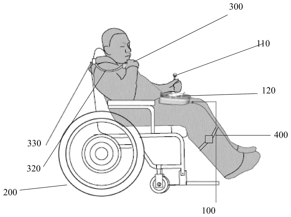
FIG. 5shows the clamp330of a chin stick300attached to a user's wheel chair200. The chin stick300and controller100inFIG. 5may generate control signals for separate functions. For example, in a first person shooting game, the user may push with his left hand the joystick110on the controller100to control general directions of movement. The user may manipulate the chin stick300to aim the crosshair of his or her weapon in the game. The user may then use his right hand to push the buttons120to shoot his or her weapon in the game.
The motion sensor400may be attached to other portions of the user's body, such as his or her arms or head. The peripheral controllers are not limited to a chin stick or motion sensor, but may be any device that may convert a force or motion from a portion of the user's body into a control signal. The peripheral controllers may incorporate pressure sensors, potentiometers, gyroscopes, compasses, or any other component configured to sense motion or force. In one embodiment, a peripheral controller may incorporate a pressure sensor into a headrest. The peripheral controller may sense pressure changes from a user's head to generate, for example, control signals to shoot a weapon in a game.
The peripheral controller may communicate with the primary game controller100, which may control a game console output communication interface to relay control signals from the controller's control inputs and the peripheral controller to a game console executing the game. The game controller's game console output communication interface may communicate with the game console through a wired connection or may communicate wirelessly, such as through a WLAN, infrared, Bluetooth® standard, or any other wireless standard. The game console output communication interface and peripheral control input communication interface may be part of the same communication circuit in the controller and may use the same receiver and transmitter, or may be part of separate communication circuits.
The peripheral controller and game controller100may communicate wirelessly, such as through a Bluetooth®, WLAN, infrared, or any other wireless communication standard. AsFIG. 2Cshows, a peripheral control input communication interface on the controller100may have a wireless receiver that may communicate with one or more peripheral controllers, like a motion sensor or external joystick.FIG. 2Cshows that the peripheral controller and game controller100may communicate through a wired connection via a plurality of ports. The ports may accommodate a plurality of peripheral controller connectors, such as a USB connector, an Ethernet connector, a TRS jack, a RCA connector, EIAJ connector, a D-sub connector, or any other standard or customized connector. A port may be dedicated to a specific type of control input, such as a joystick or similar control inputs, or may be a general purpose port. The control signals received at the ports or wireless receivers may be processed by the controller100, which then transmits the processed signals to a game console executing a game. The control signals received at the ports or wireless receivers may also be directly transmitted to a game console executing a game. Control signals from control inputs on the controller100may also be directly transmitted to the game console, or may be first processed by the controller100, which may transmit the processed signals to the game console.
FIG. 6A-Cillustrates a connector of a joystick110that may be used to switch the game function of the joystick110. InFIG. 6A, the joystick110may generate control signals for a movement function. The control signals may be fed to the controller through internal electrical connections in the joystick receptacle or through an external connector115of the joystick that plugs into a port150on the controller. The operation of the joystick110may be temporarily disabled by unplugging the joystick's connector115from the controller100's port150, as shown inFIG. 6B. The movement function may be assigned to a peripheral controller, such as a chin stick, by plugging the connector of that peripheral controller to port150. An aiming function may be controlled by another peripheral controller, such as a motion sensor, by plugging its connector315into port140, as shown inFIG. 6C. A control unit in the controller may simply transmit whatever control signal is received at a port150as a movement control signal and transmit whatever control signal is received at port140as an aiming control signal. In that example, the joystick110connector may remain unplugged, and the joystick110is not used in the game. In another example, the joystick110may be plugged into port140to control the aiming function.
The data connection between the peripheral controller and the game controller100may also be wireless. For example, the control unit of the game controller100may decide to transmit control signals from the chin stick300to the a peripheral control input communication interface on the controller100based on a Bluetooth® connection with a Bluetooth® receiver on the controller.
The switching of controls is not limited to just the joystick110or chin stick300, but may involve other control inputs on the controller100and other peripheral controllers. For example, while the buttons124on the controller may have previously controlled jumping or running functions, a user may switch the function to a motion sensor400by plugging a connector of the motion sensor into the port190in Fig. C. The port190may be preprogrammed or dynamically assigned as the port associated with a jumping or running function.
In some embodiments, the game function of a control input or of a peripheral controller is not fixed, but may be reconfigured. For example, the chin stick300may be used as an input for an aiming function for one game or user, and as an input for a movement function for another game or user. The game function that a control input or peripheral controller is assigned to may be uploaded to the control unit. For example, a user profile may be uploaded, and a control unit may decide to assign a left joystick to an aiming function if the user profile indicates adequate motor control in the user's left hand. In one example, the controller100may comprise switches or other inputs for selecting which control input or peripheral controller will control a movement function. For example, a user may slide a switch on the controller to toggle between the joystick110and a peripheral controller connected to port140for the movement function. In another example, the control unit100may recognize that tapping buttons122a certain number of times will assign it to a shooting function, while moving the chin stick300in a certain direction will assign it to an aiming function.
The game function associated with a control input on the game controller100or with a peripheral controller may be reconfigured to accommodate a given mobility impaired person's particular needs. For example, for a user with sufficient motor control in his or her left hand but not the right hand, the control unit of the controller100may assign the left joystick110for game functions, such as aiming, that require high precision movements. For that user, the control unit may assign a movement function, which may require less precise inputs, to peripheral controllers such as the chin stick300or motion sensor400. In another example, for a user with limited motor control in both hands, the control unit on the primary controller100may assign the high precision aiming function to a peripheral controller like the chin stick300. For that user, the control unit may assign the lower precision movement function to the joystick110or the motion sensor400. If that user has almost no motor control in his or her hands, the control unit may assign the movement function to the motion sensor400and not use the joystick110as a game input.
The functions of the game control signals from the peripheral controllers and the game controller's100control inputs may complement each other. For example, one game may use the joystick110for controlling a general direction of movement in the game, a motion sensor400for accelerating the rate of movement in the game, buttons122for adjusting the volume in a game, buttons124for directing one or more weapons in the game to be fired, and a chin stick300for aiming the one or more weapons. One or both of the chin stick300and motion sensor400may communicate with the primary game controller100wirelessly. Alternatively, a connector315from the chin stick may be plugged into port140, while a connector from the motion sensor400may be plugged into port190. The game controller is not limited to the three ports shown in these embodiments, but may have fewer or more ports. In this example, the control unit may transmit the control signals from all the control inputs on the controller100and all the peripheral controllers to the remote game console.
The game controller system described herein makes video games more accessible for mobility impaired persons. By allowing mobility impaired persons to focus their attention on accomplishing intricate tasks in a video game, the system may alleviate or manage the pain caused by their mobility impairment. The system may allow a game user to perform intricate tasks by pairing a game controller with a peripheral controller that may be controlled by a part of the user's body that has a high degree of motor control.
Although the invention has been described in detail for the purpose of illustration based on what is currently considered to be the most practical and preferred embodiments, it is to be understood that such detail is solely for that purpose and that the invention is not limited to the disclosed embodiments, but, on the contrary, is intended to cover modifications and equivalent arrangements that are within the spirit and scope of the appended claims. For example, it is to be understood that the present invention contemplates that, to the extent possible, one or more features of any embodiment can be combined with one or more features of any other embodiment.
Claims
- A game controller, comprising: a controller body having a top surface, a bottom surface, and a peripheral edge between the top surface and the bottom surface;a first control input on the controller body, configured to generate a first control signal based on user input received by the first control input;a peripheral control input communication interface on the controller body, configured to receive a second control signal from a peripheral control input device that is separate from the controller body and receives input from a user's chin;a control unit on the controller body configured to receive the first control signal and second control signal for transmission to a remote game console;and a game console output communication interface on the controller body, connected to the control unit and configured to transmit one or more output signals based on or including the first control signal, the second control signal, or any combination thereof to a remote game console;wherein the controller body is configured to be received on the user's lap and has a rearwardly facing recess along the peripheral edge for receipt of the user's abdomen to assist in laterally stabilizing the controller on the user's lap, and wherein the peripheral control input device is configured to be positioned on the user's upper body for input from the chin.
- The game controller of claim 1 , the recess having a minimum dimension in a lateral width direction of the controller of at least 6 inches.
- The game controller of claim 1 , the recess having a maximum dimension in a lateral width direction of the controller of at most 18 inches.
- The game controller of claim 1 , the recess having a dimension in a fore-aft depth direction of the controller of at least 2 inches and at most 24 inches.
- The game controller of claim 1 , the recess having a dimension in a fore-aft depth direction of the controller of at least 5 inches and at most 16 inches.
- The game controller of claim 1 , the recess having a dimension in a lateral width direction of the controller of at least 5 inches and at most 18 inches.
- The game controller of claim 1 , the recess having a dimension in a lateral width direction of the controller of at least 8 inches and at most 16 inches.
- The game controller of claim 1 , wherein the one or more control inputs comprises a joystick, a button, a trigger, a switch, a steering wheel, or any combination thereof.
- The game controller of claim 1 , wherein the controller body further comprises a pair of downwardly facing recesses at the bottom surface thereof for receipt of a user's thighs to assist in laterally stabilizing the controller on the user's lap.
- The game controller of claim 9 , wherein each of the downwardly facing recesses has a dimension in the lateral width direction of the controller of at least 5 inches and at most 12 inches.
- The game controller of claim 9 , wherein each of the downwardly facing recesses has a dimension in the fore-aft depth direction of the controller of at least 5 inches and at most 9 inches.
- The game controller of claim 1 , wherein the peripheral control input communication interface comprises a first port associated with a first game function and a second port associated with a second game function.
- The game controller of claim 12 , wherein the first control input comprises a first connector connected to the first port, and wherein the control unit is configured to transmit the first control signal as a control signal for the first game function and to transmit the second control signal as a control signal for the second game function.
- The game controller of claim 13 , wherein the first control input comprises a first connector connected to the second port, and wherein the control unit is configured to transmit the first control signal as a control signal for the second game function and to transmit the second control signal as a control signal for the first game function.
- The game controller of claim 13 , wherein the first control input comprises a first connector that is releasably connectable to the first port and to the second port.
- The game controller of claim 13 , further comprising a third port associated with a third game function.
- The game controller system of claim 1 , wherein the peripheral control input device comprises a chin stick.
- The game controller of claim 1 , wherein the peripheral control input device comprises a joystick that is operable to receive input from a user's chin to generate the second control signal and to move based on the input.
- The game controller of claim 1 , further comprising a second peripheral control input device configured to communicate a third control signal to the peripheral control input communication interface, the second peripheral control input device being separate from the controller body, wherein the control unit on the controller body is configured to receive the third control signal for transmission to the remote game console and wherein the game console output communication interface is configured to transmit one or more output signals further based on or including the third control signal or any combination thereof to the remote game console.
- The game controller of claim 19 , wherein the second peripheral control input device comprises a motion sensor that is operable to generate the third control signal.
Disclaimer: Data collected from the USPTO and may be malformed, incomplete, and/or otherwise inaccurate.