U.S. Pat. No. 9,174,135
STORAGE MEDIUM HAVING STORED THEREIN GAME PROGRAM, GAME APPARATUS, GAME SYSTEM, AND GAME PROCESSING METHOD
AssigneeNINTENDO CO., LTD.
Issue DateJune 6, 2013
Illustrative Figure
Abstract
An input is acquired, and in accordance with the input, a sequence of game processing from beginning a predetermined game to obtaining a result of the game is performed. Then, a game image corresponding to the game processing from the beginning of the game to a state of the game still in progress is displayed on the portable display apparatus. A game image corresponding to at least part of the game processing from the beginning of the game to the state of the game still in progress is redisplayed on another display apparatus, and thereafter, a game image corresponding to the game processing until the obtaining of the result of the game is displayed on the other display apparatus.
Description
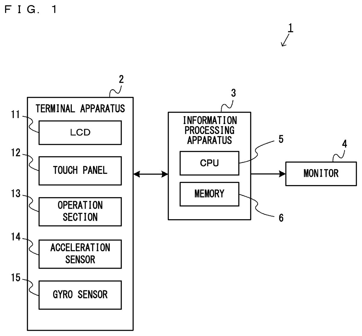
DETAILED DESCRIPTION OF NON-LIMITING EXAMPLE EMBODIMENTS With reference toFIG. 1, a description is given of an information processing apparatus for executing a game program and an information processing system including the information processing apparatus, according to an exemplary embodiment. It should be noted thatFIG. 1is a block diagram showing an example of an information processing system1including an information processing apparatus3. As an example, the information processing apparatus3is composed of a stationary game apparatus, and the information processing system1is composed of a game system including the stationary game apparatus. InFIG. 1, the information processing system1includes a terminal apparatus2, the information processing apparatus3, and a monitor4. The information processing system1according to the exemplary embodiment generates images (for example, game images) and displays the images on display apparatuses (the terminal apparatus2and the monitor4). In the information processing system1, the information processing apparatus3executes information processing in accordance with an input to the terminal apparatus2, and the images obtained as a result of the execution of the information processing are displayed on the terminal apparatus2and/or the monitor4. As described above, in the exemplary embodiment, the information processing system1is configured to achieve an input function, an information processing function, and a display function by a plurality of apparatuses. It should be noted that in another exemplary embodiment, the configuration of the information processing system1may be such that the monitor4is connected, using wired or wireless communication, to a single information processing apparatus (for example, a portable information processing apparatus) having these functions. The terminal apparatus2is an input apparatus that can be held by a user (a portable input apparatus). The terminal apparatus2is capable of communicating with the information processing apparatus3. The terminal apparatus2transmits operation data representing the operation on the terminal apparatus2to the information processing apparatus3. Further, in the exemplary embodiment, the terminal apparatus2includes a display section ...
DETAILED DESCRIPTION OF NON-LIMITING EXAMPLE EMBODIMENTS
With reference toFIG. 1, a description is given of an information processing apparatus for executing a game program and an information processing system including the information processing apparatus, according to an exemplary embodiment. It should be noted thatFIG. 1is a block diagram showing an example of an information processing system1including an information processing apparatus3. As an example, the information processing apparatus3is composed of a stationary game apparatus, and the information processing system1is composed of a game system including the stationary game apparatus.
InFIG. 1, the information processing system1includes a terminal apparatus2, the information processing apparatus3, and a monitor4. The information processing system1according to the exemplary embodiment generates images (for example, game images) and displays the images on display apparatuses (the terminal apparatus2and the monitor4).
In the information processing system1, the information processing apparatus3executes information processing in accordance with an input to the terminal apparatus2, and the images obtained as a result of the execution of the information processing are displayed on the terminal apparatus2and/or the monitor4. As described above, in the exemplary embodiment, the information processing system1is configured to achieve an input function, an information processing function, and a display function by a plurality of apparatuses. It should be noted that in another exemplary embodiment, the configuration of the information processing system1may be such that the monitor4is connected, using wired or wireless communication, to a single information processing apparatus (for example, a portable information processing apparatus) having these functions.
The terminal apparatus2is an input apparatus that can be held by a user (a portable input apparatus). The terminal apparatus2is capable of communicating with the information processing apparatus3. The terminal apparatus2transmits operation data representing the operation on the terminal apparatus2to the information processing apparatus3. Further, in the exemplary embodiment, the terminal apparatus2includes a display section (an LCD11), and therefore, the terminal apparatus2serves also as a display apparatus. When an image has been transmitted from the information processing apparatus3, the terminal apparatus2displays the image on the LCD11.
In addition, the terminal apparatus2includes a touch panel12and an operation section13as an input section. For example, the touch panel12detects the position of an input provided to a predetermined input surface (for example, a display screen of the LCD11) provided in a housing of the terminal apparatus2. Further, as an example, the operation section13includes an analog stick, a directional pad, an operation button, and the like.
In addition, the terminal apparatus2also includes an acceleration sensor14in the input section. The acceleration sensor14detects the acceleration of the terminal apparatus2in a predetermined axial direction (which is three axial directions in the exemplary embodiment, but may only need to be one or more axial directions). Further, the terminal apparatus2also includes a gyro sensor15in the input section. The gyro sensor15detects the angular velocity of the rotation of the terminal apparatus2about a predetermined axial direction (which is three axial directions in the exemplary embodiment, but may only need to be one or more axial directions). The acceleration sensor14and the gyro sensor15are sensors that detect information for calculating the orientation of the terminal apparatus2(information enabling the calculation or the estimation of the orientation). It should be noted that in another exemplary embodiment, the orientation of the terminal apparatus2may be calculated by any method. The orientation of the terminal apparatus2may be calculated using another sensor other than the above sensors, or using a camera capable of capturing the terminal apparatus2.
The information processing apparatus3performs various types of information processing performed in the information processing system1, such as the process of generating an image. In the exemplary embodiment, the information processing apparatus3has a CPU (control section)5and a memory6. The CPU5executes a predetermined information processing program (for example, a game program) using the memory6, thereby achieving various functions of the information processing apparatus3. It should be noted that the information processing apparatus3may have any configuration so long as it can perform the information processing described above. In the exemplary embodiment, the information processing apparatus3generates images (for example, game images) and outputs the generated images to the terminal apparatus2and the monitor4, which serve as display apparatuses.
The monitor4is an example of a display apparatus that displays a generated image. The monitor4is capable of receiving data transmitted from the information processing apparatus3. When an image generated by the information processing apparatus3has been transmitted to the monitor4, the monitor4displays the image.
Next, with reference toFIGS. 2 through 7, a description is given of an overview of the information processing performed by the information processing apparatus3, before the description of specific processing performed by the information processing apparatus3. It should be noted that the following descriptions are given taking, as an example of the information processing, game processing for performing a bowling game of throwing a ball object OBJ1by targeting pin objects OBJ2.FIG. 2is a diagram showing examples of images (game images) displayed in the information processing system1.FIGS. 3 through 6are diagrams showing examples of game images of a virtual world displayed on the terminal apparatus2and the monitor4.FIG. 7is a diagram showing the chronological changes in the game images displayed on the terminal apparatus2and the monitor4.
As shown inFIG. 2, in the exemplary embodiment, as an example, a game image is displayed on each of the terminal apparatus2and the monitor4. For example, the user performs a touch operation on the touch panel12while holding the terminal apparatus2such that the display screen of the terminal apparatus2is horizontal, and then performs the operation of tilting the terminal apparatus2from the horizontal state. Thus, the user can operate an object placed in a virtual world displayed on the terminal apparatus2and the monitor4.
FIG. 3shows examples of game images displayed on the terminal apparatus2and the monitor4when the user performs the operation of throwing a ball object OBJ1in the bowling game. As shown inFIGS. 3 and 7, on the monitor4, for example, a game image (a pin arrangement image) is displayed in which a plurality of pin objects OBJ2arranged at the far end (on a so-called pin deck) of a lane used in the bowling game are viewed in the direction of throwing the ball object OBJ1(hereinafter, this direction is referred to as a “front direction”). Here, on the monitor4, the pin deck is mainly displayed on which the pin objects OBJ2are arranged to serve as targets to be knocked down by causing the ball object OBJ1to collide with them. In other words, the pin deck is a space for placing targets (game targets) that serve as the targets of movement of an operation object when a game is performed. Thus, a space for throwing the ball object OBJ1, that is, a space for placing the operation object to be operated when the game is performed, is not displayed because the space is outside the display area.
On the other hand, on the LCD11of the terminal apparatus2, for example, the lane used in the bowling game is displayed such that the front-back direction of the lane is the left-right direction of the terminal apparatus2, and a game image (an image including a throwing area) is displayed in which the near end of the lane (that is, a part of the lane across a throwing foul line in the front-back direction) is viewed from above (hereinafter, this direction is referred to as a “top-view direction”). In the lane displayed on the LCD11, the throwing area is set on the near side of a first line, which corresponds to the foul line in bowling, and a tilt-operation-allowed area is set on the far side of the first line. The throwing area is an area for performing a touch operation on the inside of the throwing area via the touch panel12, thereby enabling the throwing of the ball object OBJ1forward in the lane. As an example, the user of the terminal apparatus2performs a touch operation on the inside of the throwing area so as to slide from the near end to the far end of the lane, thereby throwing the ball object OBJ1to the far end of the lane in a throwing direction based on the direction of the slide operation and at a throwing speed based on the speed of the slide operation. Further, the tilt-operation-allowed area is an area allowing a change in the moving direction of the ball object OBJ1after being thrown, by performing the operation of tilting the body of the terminal apparatus2.
As shown inFIG. 4, while the ball object OBJ1is moving in the tilt-operation-allowed area, it is possible to change the moving direction of the ball object OBJ1by tilting the body of the terminal apparatus2about a predetermined axis of the terminal apparatus2(for example, an X-axis shown inFIG. 4, which is the left-right direction of the terminal apparatus2) from the horizontal state. Specifically, the moving direction of the ball object OBJ1changes such that the ball object OBJ1curves in the direction of tilting the lane, displayed on the LCD11, to the left or right from the horizontal state, and by a degree based on the angle of tilt from the horizontal state. For example, if the user tilts the terminal apparatus2about the X-axis shown inFIG. 4such that the lane displayed on the LCD11is downward to the right, the moving direction of the ball object OBJ1is set such that the ball object OBJ1moving in the tilt-operation-allowed area curves to the right in accordance with the angle of tilt downward to the right from the horizontal state. It should be noted that as shown inFIG. 4, the tilt-operation-allowed area allowing an operation on the moving direction of the ball object OBJ1is set in an area extending to a second line provided on the near side of the pin deck on which the pin objects OBJ2are arranged. Thus, after the ball object OBJ1reaches the second line, it is not possible to perform the operation of changing the moving direction of the ball object OBJ1.
As shown inFIGS. 3,4, and7, while the ball object OBJ1is moving in the tilt-operation-allowed area, on the monitor4, the game image (the pin arrangement image) continues to be displayed in which the plurality of pin objects OBJ2arranged on the pin deck are viewed in the front direction, and the game image does not change in accordance with the movement of the ball object OBJ1. On the other hand, on the LCD11of the terminal apparatus2, a game image (a tilt operation area image) is displayed that is obtained by moving its viewpoint to the far end of the lane in accordance with the movement of the ball object OBJ1and viewing the lane and the ball object OBJ1in the top-view direction.
As shown inFIGS. 5 and 7, if the ball object OBJ1has reached the second line, the movement of the ball object OBJ1stops in the game image displayed on the LCD11of the terminal apparatus2. Then, on the LCD11, a top-view image of the lane is displayed in which the plurality of pin objects OBJ2are arranged and the ball object OBJ1is stopped on the second line. Additionally, an image that prompts the user to view the game image displayed on the monitor4is displayed. For example, on the LCD11, an image obtained by reducing the brightness of the top-view image to reduce the visibility of the top-view image (a stopped image obtained by darkening the top-view image of the lane) is displayed, and a character image that prompts the user to view the game image displayed on the monitor4(for example, “Watch the TV!”) is displayed on the top-view image in a superimposed manner. It should be noted that the method of reducing the visibility of the top-view image may be another method. For example, the visibility may be reduced by increasing the brightness of the top-view image. Alternatively, the visibility may be reduced by changing the saturation or the hue of the top-view image. Yet alternatively, the visibility may be reduced by hiding the top-view image.
Meanwhile, if the ball object OBJ1has reached the second line, on the monitor4, a front-direction image (a reproduction image) in which the ball object OBJ1moves again from the near end (for example, immediately after the throwing) to the far end of the lane is reproduced after a predetermined time has elapsed since the ball object OBJ1reached the second line. Here, in the game image displayed on the monitor4, the motion of the ball object OBJ1moving on the lane is the reproduction of the motion of the ball object OBJ1once displayed on the LCD11of the terminal apparatus2. This enables the user of the terminal apparatus2to view again the motion of the ball object OBJ1moving on the lane by the operation performed by the user themselves. Further, as shown inFIG. 5, while the ball object OBJ1is moving in the tilt-operation-allowed area, on the monitor4, a front-direction game image is displayed that is obtained by once moving the position of the viewpoint in the pin arrangement image to the near end of the lane, and thereafter, a front-direction game image is displayed that is obtained by bringing its viewpoint closer to the ball object OBJ1in accordance with the position to which the ball object OBJ1moves when the movement of the ball object OBJ1is reproduced. Thus, the user of the terminal apparatus2can view again from a different angle the motion of the ball object OBJ1that the user has viewed once on the LCD11of the terminal apparatus2.
As shown inFIGS. 6 and 7, if the ball object OBJ1has reached the second line again in the reproduction image displayed on the monitor4, the movement of the ball object OBJ1from the second line to the far end of the lane continues in accordance with the moving direction and the moving speed of the ball object OBJ1at the time when the ball object OBJ1has reached the second line. Then, in accordance with the state of collision between the ball object OBJ1and the pin objects OBJ2, on the monitor4, a front-direction game image (a throwing result image) is displayed in which the pin objects OBJ2fall down. On the other hand, during the period from when the ball object OBJ1crosses the second line to when the ball object OBJ1collides with the pin objects OBJ2and the result of the throwing is displayed, on the LCD11of the terminal apparatus2, the image that prompts the user to view the game image displayed on the monitor4continues to be displayed.
Here, the number of pin objects OBJ2falling down as a result of the collision between the ball object OBJ1and the pin objects OBJ2serves as points in one throw in the bowling game, and indicates the result of the game obtained by the operation performed by the user of the terminal apparatus2. That is, a game image in which the pin objects OBJ2fall down as a result of the collision between the ball object OBJ1and the pin objects OBJ2is an image representing the result of the game of throwing the ball object OBJ1once by targeting the pin objects OBJ2. Thus, on the monitor4, after the reproduction image is displayed in which the ball object OBJ1rolls on the lane, the process is displayed until the result of the game of throwing the ball object OBJ1once is obtained. This enables not only the user of the terminal apparatus2to view the content until the result of the game that the user is playing, but also another person to share the content until the result of the game. On the other hand, on the LCD11of the terminal apparatus2, the process is displayed only until the state of the game still in progress in the sequence of the game from when the operation of throwing the ball object OBJ1into the lane is performed to when the result of the game using the thrown ball object OBJ1is obtained. This makes it necessary to view the monitor4to know the result of the game. Thus, the user of the terminal apparatus2operates the terminal apparatus2while viewing it, and is also prompted to view the screen of the monitor4to view the result of the operation. This makes it possible to achieve a game where the user themselves uses two display screens. Further, the period until the image that prompts the user to view the game image displayed on the monitor4is displayed on the LCD11of the terminal apparatus2is also the period during which the user can control the action of the ball object OBJ1by operating the terminal apparatus2. Thus, the display of the prompting image on the LCD11can be used also to inform the user that the operation-allowed period has ended.
It should be noted that the reproduction image displayed on the monitor4may be started at any time during the period from when the user throws the ball object OBJ1into the lane to when the ball object OBJ1reaches the second line. Further, the reproduction image displayed on the monitor4is displayed after a predetermined time has elapsed since the ball object OBJ1reached the second line in the game image displayed on the terminal apparatus2. This allows the user of the terminal apparatus2sufficient time to shift their eyes from the LCD11to the monitor4. If, however, such effects are not desired, the display of the reproduction image may be started at another time. For example, the display of the reproduction image may be started on the monitor4at the same time as the ball object OBJ1reaches the second line in the game image displayed in the terminal apparatus2. Alternatively, the display of the reproduction image may be started on the monitor4at a predetermined time before the ball object OBJ1reaches the second line.
In addition, the reproduction image displayed on the monitor4may be an image obtained by omitting the state of the game still in progress in the sequence of the game from when the user throws the ball object OBJ1into the lane to when the pin objects OBJ2fall down as a result of the collision between the ball object OBJ1and the pin objects OBJ2. As an example, the reproduction image displayed on the monitor4represents the period from when the user throws the ball object OBJ1into the lane to immediately after the user throws the ball object OBJ1into the lane. Then, on the monitor4, an image is displayed that is obtained by omitting the state of the game still in progress in the sequence of the game to represent the period from after the ball object OBJ1reaches the second line to when the pin objects OBJ2fall down as a result of the collision between the ball object OBJ1and the pin objects OBJ2.
Next, a detailed description is given of the information processing (for example, game processing) performed by the information processing apparatus3. It should be noted that the information processing is described below using an example where game processing is performed on the sequence of the game until the result is obtained of the bowling game of throwing the ball object OBJ1once by operating the ball object OBJ1such that the pin objects OBJ2are the targets of movement of the ball object OBJ1. First, with reference toFIG. 8, a description is given of main data used in the information processing. It should be noted thatFIG. 8is a diagram showing examples of main data and programs stored in the memory6of the information processing apparatus3.
As shown inFIG. 8, the following are stored in the data storage area of the memory6: terminal operation data Da; throwing direction/speed data Db; tilt angle data Dc; moving direction/speed data Dd; ball position data De; pin position data Df; time count data Dg; first virtual camera data Dh; second virtual camera data Di; image data Dj; and the like. It should be noted that the memory6may store, as well as the data shown inFIG. 8, data and the like necessary for the information processing (the game processing), such as data used in an application to be executed. Further, in the program storage area of the memory6, various programs Pa included in the information processing program (the game processing) are stored.
The terminal operation data Da has stored therein a series of pieces of operation information (terminal operation data) transmitted as transmission data from the terminal apparatus2, and is updated to the latest terminal operation data. For example, the terminal operation data Da includes touch input data Da1, angular velocity data Da2, acceleration data Da3, and the like. The touch input data Da1is data representing the touch position of a touch operation on the touch panel12, and stores at least data representing the latest touch position and data representing the touch position used in the previous processing. The angular velocity data Da2is data representing the angular velocity generated in the terminal apparatus2, and is data representing the angular velocity output from the gyro sensor15. The acceleration data Da3is data representing the acceleration generated in the terminal apparatus2, and is data representing the acceleration output from the acceleration sensor14.
The throwing direction/speed data Db is data representing the direction (throwing direction) and the speed (throwing speed) of throwing the ball object OBJ1into the lane, and is stored, for example, as vector data in the virtual world.
The tilt angle data Dc is data representing the angle of tilt of the body of the terminal apparatus2from the horizontal state.
The moving direction/speed data Dd is data representing the direction (moving direction) and the speed (moving speed) of the thrown ball object OBJ1moving on the lane, and is stored, for example, as vector data in the virtual world.
The ball position data De is data representing the position of the ball object OBJ1moving on the lane, and stores history data of the position of the ball object OBJ1, from when the ball object OBJ1is thrown into the lane to when the result of the game is obtained.
The pin position data Df is data representing the position of each of the plurality of pin objects OBJ2.
The time count data Dg is data for counting the time elapsed since the ball object OBJ1reached the second line.
The first virtual camera data Dh is data regarding a first virtual camera placed in the virtual world to obtain a game image to be displayed on the LCD11of the terminal apparatus2, and is data representing the position, the orientation, the viewing angle, and the like of the first virtual camera in the virtual world.
The second virtual camera data Di is data regarding a second virtual camera placed in the virtual world to obtain a game image to be displayed on the monitor4, and is data representing the position, the orientation, the viewing angle, and the like of the second virtual camera in the virtual world.
The image data Dj includes object image data Dj1, background image data Dj2, and the like. The object image data Dj1is data for placing objects in the virtual world to generate a game image. The background image data Dj2is data for placing a background in the virtual world to generate a game image.
Next, with reference toFIGS. 9 and 10, a detailed description is given of the information processing (the game processing) performed by the information processing apparatus3. It should be noted thatFIG. 9is a flow chart showing an example of the first half of the information processing performed by the information processing apparatus3.FIG. 10is a flow chart showing an example of the second half of the information processing performed by the information processing apparatus3. Here, in the flow charts shown inFIGS. 9 and 10, a description is given mainly of, in the information processing performed by the information processing apparatus3, the process of displaying objects on the terminal apparatus2and the monitor4. Detailed descriptions of other processes not directly related to these processes are omitted.
The CPU5initializes the memory6and the like, and loads the information processing program stored in a non-volatile memory or an optical disk included in the information processing apparatus3into the memory6. Then, the CPU5starts the execution of the information processing program. The flow charts shown inFIGS. 9 and 10are flow charts showing the processing performed after the above processes are completed.
It should be noted that the processes of all the steps in the flow chart shown inFIGS. 9 and 10are merely illustrative. Thus, the processing order of the steps may be changed, or another process may be performed in addition to, and/or instead of, the processes of all the steps, so long as similar results are obtained. Further, in the exemplary embodiment, a description is given on the assumption that the CPU5performs the processes of all the steps in the flow chart. Alternatively, a processor or a dedicated circuit other than the CPU may perform the processes of some or all of the steps in the flow chart.
Referring toFIG. 9, the CPU5performs an initialization process (step41), and proceeds to the subsequent step. For example, the CPU5places a lane and a plurality of pin objects OBJ2used in a bowling game, thereby constructing a virtual world to be displayed on the terminal apparatus2and the monitor4. Then, the CPU5initializes the parameters to be used in the game processing. For example, the CPU5places a first virtual camera immediately above the near end of the lane in the virtual world, and initializes the orientation of the first virtual camera such that the direction of the line of sight of the first virtual camera is the vertical direction in the virtual world, thereby updating the first virtual camera data Dh. Further, the CPU5places a second virtual camera above the far end of the lane in the virtual world, and initializes the orientation of the second virtual camera such that the direction of the line of sight of the second virtual camera is the front direction with the fixation point of the second virtual camera being an area in the vicinity of the pin deck on which the plurality of pin objects OBJ2are arranged, thereby updating the second virtual camera data Di. Further, on the basis of the data output from the acceleration sensor14and representing the acceleration of the terminal apparatus2, the CPU5calculates the direction of gravity applied to the terminal apparatus2, and calculates and initializes the tilt angle of the terminal apparatus2with respect to the direction of gravity (for example, the direction and the angle of tilting the display screen of the terminal apparatus2with respect to the horizontal direction), thereby updating the tilt angle data Dc.
Next, the CPU5acquires operation data from the terminal apparatus2, thereby updating the terminal operation data Da (step42), and proceeds to the subsequent step. For example, the CPU5updates the latest data in the touch input data Da1using data representing the touch position of a touch operation on the touch panel12. Further, the CPU5updates the angular velocity data Da2using the data output from the gyro sensor15and representing the angular velocity generated in the terminal apparatus2. Further, the CPU5updates the acceleration data Da3using the data output from the acceleration sensor14and representing the acceleration generated in the terminal apparatus2.
Next, the CPU5determines whether or not the operation data acquired in the above step42indicates a touch operation on the throwing area (step43). For example, the CPU5determines whether or not the operation data acquired in the above step42indicates a touch operation on the inside of the throwing area set in the lane (seeFIG. 3). Then, if the operation data indicates a touch operation on the throwing area, the CPU5proceeds to step44. If, on the other hand, the operation data does not indicate a touch operation on the throwing area, the CPU5proceeds to step45.
In step44, the CPU5sets the throwing direction and the throwing speed in accordance with the touch operation, and proceeds to step47. For example, if the touch operation is a touch operation of sliding on the touch panel12, the CPU5determines that a direction, in the virtual world, corresponding to the direction of the slide is the throwing direction, and calculates the throwing speed in accordance with the speed of the slide, thereby updating the throwing direction/speed data Db using the calculated throwing direction and throwing speed. It should be noted that the throwing speed to be calculated in accordance with the speed of the slide may be provided with a predetermined upper limit.
In step45, the CPU5determines whether or not the operation data acquired in the above step42indicates either the operation of stopping the touch operation on the throwing area (a touch-off operation on the throwing area), or a touch operation of moving from the inside to the outside of the throwing area (the start of throwing). Then, if it has been determined that the operation data indicates either a touch-off operation on the throwing area or a touch operation of moving from the inside to the outside of the throwing area, the CPU5proceeds to step46. If it has been determined that the operation data indicates neither a touch-off operation nor a touch operation of moving from the inside to the outside of the throwing area, the CPU5proceeds to step47.
In step46, the CPU5starts the movement of a ball object OBJ1on the basis of the touch position set in the previous processing and the currently set throwing direction and throwing speed, and proceeds to step47. For example, with reference to the touch input data Da1and the throwing direction/speed data Db, the CPU5acquires the touch position set in the previous processing and the currently set throwing direction and throwing speed. Then, the CPU5sets the position, the moving direction, and the moving speed of the ball object OBJ1in the virtual world such that the ball object OBJ1moves from a position, in the virtual world, overlapping the touch position in the throwing direction and at the throwing speed, thereby updating the latest position in the history data managed in the ball position data De and the moving direction and the moving speed in the moving direction/speed data Dd.
In step47, on the basis of the angular velocity data Da2, the CPU5calculates the tilt angle of the terminal apparatus2, and proceeds to the subsequent step. For example, the CPU5calculates a new tilt angle by adding the amount of rotation based on the angular velocity data acquired in step42, to the tilt angle indicated by the tilt angle data Dc (for example, the tilt of the display screen of the terminal apparatus2with respect to the horizontal direction), thereby updating the tilt angle data Dc using the new tilt angle. It should be noted that in the above step47, the CPU5may correct the tilt angle every time or at predetermined intervals, using the direction of gravity based on the acceleration data Da3. Alternatively, in the above step47, the CPU5may calculate the tilt angle using only the direction of gravity based on the acceleration data Da3. If the CPU5calculates the tilt angle using only the direction of gravity based on the acceleration data Da3, the CPU5may perform the above step47after the determination is affirmative in step48described later.
Next, with reference to the ball position data De, the CPU5determines whether or not the ball object OBJ1is moving in the tilt-operation-allowed area (seeFIGS. 3 and 4) (step48). Then, if the ball object OBJ1is moving in the tilt-operation-allowed area, the CPU5proceeds to step49. If, on the other hand, the ball object OBJ1is not moving in the tilt-operation-allowed area, the CPU5proceeds to step61(FIG. 10).
In step49, the CPU5changes the moving direction of the ball object OBJ1in accordance with the tilt angle of the terminal apparatus2, and proceeds to the subsequent step. For example, the CPU5calculates the angle of tilt of the lane, displayed on the LCD11, to the left or right with respect to the horizontal direction (for example, the angle of tilt of the display screen of the terminal apparatus2with respect to the horizontal direction about a predetermined axis of the terminal apparatus2(for example, the X-axis directed in the left-right direction of the terminal apparatus2when the lane is displayed such that the left-right direction of the terminal apparatus2is the front-back direction of the lane (see FIG.4))), using the tilt angle indicated by the tilt angle data Dc. Then, the CPU5changes the moving direction set in the moving direction/speed data Dd such that the moving direction of the ball object OBJ1changes by the amount of change based on the angle of tilt of the lane to the left or right and in the direction of the tilt, thereby updating the moving direction. It should be noted that if the ball object OBJ1is placed in an area where the moving direction of the ball object OBJ1is fixed in a predetermined direction in the virtual world (for example, an area where the ball object OBJ1may fall into a gutter), the CPU5may set the moving direction as the predetermined direction.
Next, the CPU5causes the ball object OBJ1to move on the basis of the ball position data De and the moving direction/speed data Dd (step50), and proceeds to the subsequent step. For example, the CPU5moves the position of the ball object OBJ1from the latest position in the virtual world indicated in the history data managed in the ball position data De, in the moving direction indicated by the moving direction/speed data Dd and at the moving speed indicated by the moving direction/speed data Dd, adds data representing the resulting position as the latest position in the history data, and sets the latest position as the position of the ball object OBJ1to be displayed on the LCD11.
Next, the CPU5moves the first virtual camera in accordance with the latest position of the ball object OBJ1(step51), and proceeds to the subsequent step. For example, the CPU5sets the position of the first virtual camera immediately above a center position in the lane, which is located ahead, by a predetermined distance in the lane, of the latest position of the ball object OBJ1set in the above step50, without changing the distance of the first virtual camera from the lane in the up-down direction, thereby updating the first virtual camera data Dh using the set position.
Next, the CPU5determines whether or not the ball object OBJ1has reached the second line (step52). Then, if the ball object OBJ1has reached the second line, the CPU5proceeds to step53. If, on the other hand, the ball object OBJ1has not reached the second line, the CPU5proceeds to step61(FIG. 10).
In step53, the CPU5stops the movement of the ball object OBJ1, and sets a flag for displaying an image that prompts the user to view the game image displayed on the monitor4. Then, the CPU5starts the process of initializing the count data in the time count data Dg and thereafter starting to count time, thereby updating the time count data Dg (step54), and proceeds to step61(FIG. 10).
Referring next toFIG. 10, in step61, with reference to the time count data Dg, the CPU5determines whether or not a predetermined time has elapsed. Here, the predetermined time is used to allow the user of the terminal apparatus2sufficient time to shift their eyes from the LCD11to the monitor4, and is set to, for example, several seconds. Then, if the predetermined time has elapsed since the counting of time started, the CPU5proceeds to step62. If, on the other hand, the predetermined time has not elapsed or time has not been counted, the CPU5proceeds to step66.
In step62, the CPU5reproduces the movement of the ball object OBJ1from immediately after the ball object OBJ1is thrown to when the ball object OBJ1reaches the second line, and proceeds to the subsequent step. For example, the CPU5sets a reproduction display position of the ball object OBJ1to be displayed on the monitor4in order starting from the earliest position data in the history data managed in the ball position data De.
Next, the CPU5moves the second virtual camera in accordance with the reproduction display position of the ball object OBJ1set in the above step62(step63), and proceeds to the subsequent step. As an example, if the earliest position data has been set as the reproduction display position in the history data, the CPU5sets the position of the second virtual camera immediately above a center position in the lane, which is located behind the reproduction display position by a predetermined distance in the lane, and sets the direction of the line of sight of the second virtual camera to the front direction of the lane, thereby updating the second virtual camera data Di. Then, during the period until the reproduction display position reaches a predetermined position in the lane, the CPU5does not change the position of the second virtual camera. After the reproduction display position reaches the predetermined position, the CPU5moves the position of the second virtual camera so as to bring the second virtual camera closer to the reproduction display position, thereby updating the second virtual camera data Di.
Next, the CPU5determines whether or not the reproduction display position of the ball object OBJ1set in the above step62has reached the second line (step64). Then, if the reproduction display position has reached the second line, the CPU5proceeds to step65. If, on the other hand, the reproduction display position has not reached the second line, the CPU5proceeds to step66.
In step65, in accordance with the moving direction and the moving speed of the ball object OBJ1when the ball object OBJ1has reached the second line, the CPU5causes the ball object OBJ1to move into the pin deck, and proceeds to step66. For example, on the basis of the moving direction and the moving speed of the ball object OBJ1when the ball object OBJ1has reached the second line, that is, the moving direction and the moving speed currently set in the moving direction/speed data Dd, the CPU5moves the position of the ball object OBJ1from the position of the ball object OBJ1having reached the second line, that is, the latest position in the history data managed in the ball position data De, to the inside of the pin deck, adds data representing the resulting position as the latest position in the history data, and sets the latest position as the position of the ball object OBJ1to be displayed on the monitor4. It should be noted that in the above step65, for example, the CPU5initializes the count data in the time count data Dg so that the processes of the above steps62through65will not be performed in the following processing.
In step66, the CPU5determines whether or not the ball object OBJ1has reached the inside of the pin deck. For example, if the latest position in the history data managed in the ball position data De has crossed the second line, the CPU5determines that the ball object OBJ1has reached the inside of the pin deck. Then, if the ball object OBJ1has reached the inside of the pin deck, the CPU5proceeds to step67. If, on the other hand, the ball object OBJ1has not reached the inside of the pin deck, the CPU5proceeds to step68.
In step67, on the basis of the moving direction and the moving speed of the ball object OBJ1, the CPU5causes the ball object OBJ1to move, and in accordance with the state of collision between the ball object OBJ1and the pin objects OBJ2, the CPU5represents the state where the pin objects OBJ2are knocked down. Then, the CPU5proceeds to step68. For example, on the basis of the moving direction and the moving speed set in the moving direction/speed data Dd, the CPU5moves within the pin deck the position of the ball object OBJ1from the latest position in the history data managed in the ball position data De. In accordance with the position data of each of the plurality of pin objects OBJ2indicated by the pin position data Df and the position of the ball object OBJ1after the movement, the CPU5performs collision detection between the ball object OBJ1and the pin objects OBJ2and also collision detection among the pin objects OBJ2, and moves the positions of the objects in accordance with the collision detection. Then, the CPU5updates the latest position in the ball position data De and the position of each of the pin objects OBJ2in the pin position data Df, using the calculated positions of the objects.
It should be noted that in the processing described above, the position and the orientation of the second virtual camera are not changed even after the above step65is performed or even after the above step67is performed. Thus, after the ball object OBJ1enters the pin deck, the viewpoint and the line of sight of the game image displayed on the monitor4are fixed. If, however, the viewpoint and the line of sight of the game image displayed on the monitor4are to be changed after the ball object OBJ1enters the pin deck, the position and/or the orientation of the second virtual camera may be changed after the above step65is performed and/or after the above step67is performed. In this case, the position and/or the orientation of the second virtual camera may be changed in accordance with the position of the ball object OBJ1after the ball object OBJ1enters the pin deck.
In step68, the CPU5generates a terminal apparatus game image to be displayed on the terminal apparatus2, and proceeds to the subsequent step. For example, the CPU5reads, from the memory6, data indicating the results of the game processing performed in the above steps42through67, and reads, from a VRAM (video RAM) or the like, data necessary for generating a terminal apparatus game image. Then, the CPU5generates a terminal apparatus game image using the read data, and stores the generated terminal apparatus game image in the VRAM. As an example, the terminal apparatus game image may be generated as a three-dimensional (or two-dimensional) CG image by: placing the ball object OBJ1and the pin objects OBJ2on the lane in the virtual world on the basis of the position in the ball position data De set as the position of the ball object OBJ1to be displayed on the LCD11and the positions indicated by the pin position data Df; and calculating the virtual world viewed from the first virtual camera placed on the basis of the first virtual camera data Dh. It should be noted that if a flag for displaying an image that prompts the user to view the game image displayed on the monitor4is set, the CPU5generates a display image obtained by reducing the visibility of the terminal apparatus game image generated immediately before the flag has been set, and superimposes on the generated display image a character image that prompts the user to view the game image displayed on the monitor4(seeFIGS. 5 and 6), thereby generating a terminal apparatus game image to be displayed on the LCD11.
Next, the CPU5generates a monitor game image to be displayed on the monitor4(step69), and proceeds to the subsequent step. For example, the CPU5reads, from the memory6, data indicating the results of the game processing performed in the above steps42through67, and reads, from the VRAM or the like, data necessary for generating a monitor game image. Then, the CPU5generates a monitor game image using the read data, and stores the generated monitor game image in the VRAM. As an example, the monitor game image may be generated as a three-dimensional CG image by: placing the ball object OBJ1and the pin objects OBJ2on the lane in the virtual world on the basis of the position in the ball position data De set as the position of the ball object OBJ1to be displayed on the monitor4and the positions indicated by the pin position data Df; and calculating the virtual world viewed from the second virtual camera placed on the basis of the second virtual camera data Di.
Next, the CPU5transmits the terminal apparatus game image to the terminal apparatus2(step70), and proceeds to the subsequent step. For example, the terminal apparatus game image is received by the terminal apparatus2, and is output to and displayed on the LCD11. It should be noted that the terminal apparatus game image may be subjected to a predetermined compression process when transmitted from the information processing apparatus3to the terminal apparatus2. In this case, data of the terminal apparatus game image subjected to the compression process is sent to the terminal apparatus2, and is subjected to a predetermined decompression process by the terminal apparatus2. Thereafter, the terminal apparatus game image is displayed.
Next, the CPU5outputs the monitor game image to the monitor4(step71), and proceeds to the subsequent step. For example, the monitor game image is acquired by the monitor4, and is output to and displayed on the display screen of the monitor4.
Next, the CPU5determines whether or not the game is to be ended (step72). A game in the game processing refers to the period from when the operation of throwing the ball object OBJ1is performed to when the number of pin objects OBJ2knocked down by the ball object OBJ1thrown once by the throwing operation is definitively determined. Thus, the number of pin objects OBJ2is defined as the result of the game. Then, in the above step72, examples of conditions for ending the game include: the definitive determination of the result of the game; and the fact that the user has performed the operation of ending the game. If the game is not to be ended, the CPU5returns to the above step42, and repeats the process thereof. If the game is to be ended, the CPU5ends the processing indicated in the flow chart. Thereafter, the CPU5repeatedly performs a series of processes of steps42through72until it is determined in step72that the game is to be ended.
It should be noted that in the above exemplary embodiment, the information processing system1includes only one terminal apparatus2. Alternatively, the information processing system1may be configured to include a plurality of terminal apparatuses2. That is, the information processing apparatus3may be capable of wirelessly communicating with each of the plurality of terminal apparatuses2, and may transmit image data to the terminal apparatus2and receive terminal operation data from the terminal apparatus2. Then, lanes different from each other may be set for the terminal apparatuses2and displayed on the respective LCDs11, and the CPU5may alternately prompt users to perform the operation of throwing the ball object OBJ1, thereby displaying on the monitor4the reproduction images of the lanes on which the throwing operations have been performed. In this case, when the information processing apparatus3wirelessly communicates with each of the plurality of terminal apparatuses2, the information processing apparatus3may perform the wireless communication with the terminal apparatus2in a time division manner or in a frequency division manner.
In addition, the terminal apparatus2described above functions as a so-called thin client terminal, which does not perform the series of processes described with reference toFIGS. 9 and 10or the information processing performed by the information processing apparatus3. For example, if information processing is executed by a plurality of information processing apparatuses, it is necessary to synchronize the processing executed by the information processing apparatuses, which complicates the processing. In contrast, as in the above exemplary embodiment, if information processing is executed by one information processing apparatus3, and the terminal apparatus2receives and displays an image (that is, if the terminal apparatus2is a thin client terminal), it is not necessary to synchronize the processing among a plurality of information processing apparatuses, which can simplify the processing. The terminal apparatus2, however, may be an apparatus having the function of performing predetermined information processing by a predetermined program (a game program or an information processing program), such as a handheld game apparatus. In this case, in the above exemplary embodiment, at least some of the series of processes to be performed by the information processing apparatus3may be performed by the terminal apparatus2. As an example, if a game image is displayed on each of a plurality of terminal apparatus, using at least one terminal apparatus capable of executing all of the series of processes described above, one of the terminal apparatuses capable of executing all of the series of processes serves as a main process execution apparatus that executes the series of processes, so that the main process execution apparatus transmits game images based on the orientations of and operations on the other terminal apparatuses to the other terminal apparatuses. This makes it possible to output a similar game image to each of the terminal apparatuses and display the game image on the terminal apparatus.
It should be noted that the above descriptions are given using the example where the information processing apparatus3performs the information processing. Alternatively, another apparatus other than the terminal apparatus2may perform at least some of the processing steps in the processing. For example, if the information processing apparatus3is further configured to communicate with another apparatus other than the terminal apparatus2(for example, another server, another game apparatus, or another mobile terminal), the other apparatus may cooperate to perform the processing steps in the processing. Another apparatus may thus perform at least some of the processing steps in the processing, which enables processing similar to that described above. Further, the processing described above can be performed by a processor or the cooperation of a plurality of processors, the processor and the plurality of processors contained in an information processing system including at least one information processing apparatus. Further, in the exemplary embodiment, the processing indicated in the flow chart described above is performed by the CPU5of the information processing apparatus3executing a predetermined game program. Alternatively, some or all of the game processing indicated in the flow chart may be performed by a dedicated circuit included in the information processing apparatus3.
Here, the above variations make it possible to achieve the exemplary embodiment also by a system form such as cloud computing, or a system form such as a distributed wide area network or a local area network. For example, in a system form such as a distributed local area network, it is possible to execute the processing between a stationary information processing apparatus (a stationary game apparatus) and a handheld information processing apparatus (a handheld game apparatus) by the cooperation of the apparatuses. It should be noted that, in these system forms, there is no particular limitation on which apparatus performs the process of each step of the processing described above. Thus, it goes without saying that it is possible to achieve the exemplary embodiment by sharing the processing in any manner.
In addition, the processing orders, the setting values, the conditions used in the determinations, and the like that are used in the game processing described above are merely illustrative. Thus, it goes without saying that the exemplary embodiment can be achieved also with other orders, other values, and other conditions. Further, the exemplary embodiment is described above taking a bowling game as an example of the game processing. Alternatively, the exemplary embodiment can be achieved not only by game processing but also by general information processing.
In addition, the program may be supplied to the information processing apparatus3not only through an external storage medium such as the external memory45, but also through a wired or wireless communication link. Further, the program may be stored in advance in a non-volatile storage device included in the information processing apparatus3. It should be noted that examples of an information storage medium having stored therein the program may include CD-ROMs, DVDs, optical disk storage media similar to these, flexible disks, hard disks, magneto-optical disks, and magnetic tapes, as well as non-volatile memories. Alternatively, an information storage medium having stored therein the program may be a volatile memory for storing the program. It can be said that such a storage medium is a storage medium readable by a computer or the like. For example, it is possible to provide the various functions described above by causing a computer or the like to load a program from the storage medium and execute it.
The systems, devices and apparatuses described herein may include one or more processors, which may be located in one place or distributed in a variety of places communicating via one or more networks. Such processor(s) can, for example, use conventional 3D graphics transformations, virtual camera and other techniques to provide appropriate images for display. By way of example and without limitation, the processors can be any of: a processor that is part of or is a separate component co-located with the stationary display and which communicates remotely (e.g., wirelessly) with the movable display; or a processor that is part of or is a separate component co-located with the movable display and communicates remotely (e.g., wirelessly) with the stationary display or associated equipment; or a distributed processing arrangement some of which is contained within the movable display housing and some of which is co-located with the stationary display, the distributed portions communicating together via a connection such as a wireless or wired network; or a processor(s) located remotely (e.g., in the cloud) from both the stationary and movable displays and communicating with each of them via one or more network connections; or any combination or variation of the above.
The processors can be implemented using one or more general-purpose processors, one or more specialized graphics processors, or combinations of these. These may be supplemented by specifically-designed ASICs (application specific integrated circuits) and/or logic circuitry. In the case of a distributed processor architecture or arrangement, appropriate data exchange and transmission protocols are used to provide low latency and maintain interactivity, as will be understood by those skilled in the art.
Similarly, program instructions, data and other information for implementing the systems and methods described herein may be stored in one or more on-board and/or removable memory devices. Multiple memory devices may be part of the same device or different devices, which are co-located or remotely located with respect to each other.
While some exemplary systems, exemplary methods, exemplary devices, and exemplary apparatuses have been described in detail above, the above descriptions are merely illustrative in all respects, and do not limit the scope of the systems, the methods, the devices, and the apparatuses. It goes without saying that the systems, the methods, the devices, and the apparatuses can be improved and modified in various manners without departing the spirit and scope of the appended claims. It is understood that the scope of the systems, the methods, the devices, and the apparatuses should be interpreted only by the scope of the appended claims. Further, it is understood that the specific descriptions of the exemplary embodiment enable a person skilled in the art to carry out an equivalent scope on the basis of the descriptions of the exemplary embodiment and general technical knowledge. It should be understood that, when used in the specification, the components and the like described in the singular with the word “a” or “an” preceding them do not exclude the plurals of the components. Furthermore, it should be understood that, unless otherwise stated, the terms used in the specification are used in their common meanings in the field. Thus, unless otherwise defined, all the jargons and the technical terms used in the specification have the same meanings as those generally understood by a person skilled in the art in the field of the exemplary embodiment. If there is a conflict, the specification (including definitions) takes precedence.
As described above, the exemplary embodiment is useful as, for example, a game program, a game apparatus, a game system, and a game processing method in order, for example, not only for a user operating a game apparatus to enjoy the content of a game, but also for another person to share the content of the game.
Claims
- A non-transitory computer-readable storage medium having stored therein a game program to be executed by a computer of an apparatus for causing an image to be displayed on each of a display screen of a portable apparatus and a separate display monitor other than the portable apparatus, the game program causing the computer to perform at least: acquiring an input;performing, in accordance with the input, a sequence of game processing from beginning a predetermined game until obtaining a particular result of game processing;displaying on the portable apparatus game images depicting game processes occurring from the beginning of the game up until a particular event state within the game in progress prior to obtaining the particular result of game processing;and redisplaying on the separate display monitor game images depicting at least part of the game processes occurring from the beginning of the game up until the particular event state within the game in progress, and thereafter displaying on the separate display monitor game images depicting game processes occurring up until the obtaining of the particular result of the game processing.
- The non-transitory computer-readable storage medium having stored therein the game program according to claim 1 , wherein in the display on the other display apparatus, after the game image corresponding to the game processing from the beginning of the game to the state of the game still in progress is displayed in the display on the portable display apparatus, the game image corresponding to the at least part of the game processing from the beginning of the game to the state of the game still in progress is redisplayed on the other display apparatus.
- The non-transitory computer-readable storage medium having stored therein the game program according to claim 1 , wherein in the display on the portable display apparatus, after the game image corresponding to the game processing from the beginning of the game to the state of the game still in progress is displayed, a visibility of an image to be displayed on the portable display apparatus is reduced.
- The non-transitory computer-readable storage medium having stored therein the game program according to claim 3 , wherein in the display on the portable display apparatus, the visibility of the image to be displayed on the portable display apparatus is reduced by reducing a brightness of the image.
- The non-transitory computer-readable storage medium having stored therein the game program according to claim 3 , wherein in the display on the portable display apparatus, the visibility of the image to be displayed on the portable display apparatus is reduced by hiding the image.
- The non-transitory computer-readable storage medium having stored therein the game program according to claim 1 , wherein in the display on the portable display apparatus, after the game image corresponding to the game processing from the beginning of the game to the state of the game still in progress is displayed, a stopped image is displayed on the portable display apparatus, the stopped image obtained by stopping progression of the game at the time of the state of the game still in progress.
- The non-transitory computer-readable storage medium having stored therein the game program according to claim 1 , wherein in the performance of the sequence of the game processing, the sequence of the game processing is performed in accordance with the input acquired from the beginning of the game to a predetermined time before the result of the game is obtained;and in the display on the portable display apparatus, a game image corresponding to the game processing from the beginning of the game to the predetermined time is displayed on the portable display apparatus.
- The non-transitory computer-readable storage medium having stored therein the game program according to claim 1 , wherein in the display on the other display apparatus, a game image is displayed on the other display apparatus, the game image obtained by viewing a virtual world from a direction different from a direction from which the game image displayed in the display on the portable display apparatus is viewed.
- The non-transitory computer-readable storage medium having stored therein the game program according to claim 1 , wherein in the display on the other display apparatus, while the game image corresponding to the game processing from the beginning of the game to the state of the game still in progress is displayed in the display on the portable display apparatus, a game image is displayed on the other display apparatus, the game image including a location where the result of the game is represented.
- The non-transitory computer-readable storage medium having stored therein the game program according to claim 8 , wherein in the display on the portable display apparatus, a game image is displayed on the portable display apparatus, the game image obtained by changing a viewpoint of the game image with a direction of a line of sight of the game image fixed until the state of the game still in progress.
- The non-transitory computer-readable storage medium having stored therein the game program according to claim 1 , wherein the other display apparatus is a stationary display apparatus.
- The non-transitory computer-readable storage medium having stored therein the game program according to claim 1 , wherein in the acquisition of the input, an input using the portable display apparatus is acquired.
- A game apparatus for causing an image to be displayed on each of a display screen of a portable apparatus and a separate display monitor other than the portable apparatus, the game apparatus including one or more processing units configured to perform functions and operate as: an acquisition unit configured to acquire an input;a game processing unit configured to perform, in accordance with the input, a sequence of game processing from beginning a predetermined game until obtaining a particular result of game processing;a first game image display control unit configured to display on the portable apparatus game images depicting game processes occurring from the beginning of the game up until a particular event state within the game in progress prior to obtaining the particular result of game processing;and a second game image display control unit configured to redisplay on the separate display monitor game images depicting at least part of the game processes occurring from the beginning of the game up until the particular event state within the game in progress, and thereafter displaying on the separate display monitor game images depicting game processes occurring up until the obtaining of the particular result of the game processing.
- A game system, including a plurality of apparatuses configured to communicate with each other, for causing an image to be displayed on each of a display screen of a portable apparatus and a separate display monitor other than the portable apparatus, the game system comprising one or more processing units configured to perform functions and operate as: an acquisition unit configured to acquire an input;a game processing unit configured to perform, in accordance with the input, a sequence of game processing from beginning a predetermined game until obtaining a particular result of game processing;a first game image display control unit configured to display on the portable apparatus game images depicting game processes occurring from the beginning of the game up until a particular event state within the game in progress prior to obtaining the particular result of game processing;and a second game image display control unit configured to redisplay on the separate display monitor game images depicting at least part of the game processes occurring from the beginning of the game up until the particular event state within the game in progress, and thereafter displaying on the separate display monitor game images depicting game processes occurring up until the obtaining of the particular result of the game processing.
- A game processing method to be executed by a processor or a cooperation of a plurality of processors of an information processing system configured to provide an image to be displayed on each of a display screen of a portable apparatus and a separate display monitor other than the portable apparatus, the game processing method comprising: acquiring an input;performing, in accordance with the input, a sequence of game processing from beginning a predetermined game until obtaining a particular result of game processing;displaying on the portable apparatus game images depicting game processes occurring from the beginning of the game up until a particular event state within the game in progress prior to obtaining the particular result of game processing;and redisplaying on the separate display monitor game images depicting at least part of the game processes occurring from the beginning of the game up until the particular event state within the game in progress, and thereafter displaying on the separate display monitor game images depicting game processes occurring up until the obtaining of the particular result of the game processing.
- The non-transitory computer-readable storage medium having stored therein the game program according to claim 1 , wherein in the display screen on the portable apparatus, the game images depicting game processes performed from the beginning of the game up until the particular event state within the game in progress is displayed on the portable apparatus, and a game process image corresponding to game processing performed after the particular event state occurs is prevented from being displayed on the portable apparatus, and in the display on the separate display monitor, after ending of a displaying of game processes occurring up until the particular event state upon the portable apparatus, the game images depicting the at least part of the game processes occurring from the beginning of the game up until the particular event state within the game in progress are redisplayed on the separate display monitor, and immediately thereafter images depicting the game processes occurring from after the particular event state up until the obtaining of the particular result of the game processing is then also displayed on the separate display monitor continuing from the redisplayed game images.
Disclaimer: Data collected from the USPTO and may be malformed, incomplete, and/or otherwise inaccurate.