U.S. Pat. No. 9,174,122
GAME CONTROLLER
AssigneeSONY CORPORATION; SONY COMPUTER ENTERTAINMENT INC.
Issue DateJuly 9, 2008
Illustrative Figure
Abstract
A technique which easily removes the motion element of the game controller which is attributed to the vibrating motion of a vibrator from the output data of an acceleration sensor or reduces the element can be achieved by the present invention. In a game controller, an acceleration sensor detects the movement of the game controller. LPF is installed at the output of the acceleration sensor. Vibrators are installed inside of a housing. The cutoff frequency of LPF is set lower than the peak value of the natural frequency of the game controller. The cutoff frequency of LPF may be set to two thirds or less of the peak value of the natural frequency of the game controller.
Description
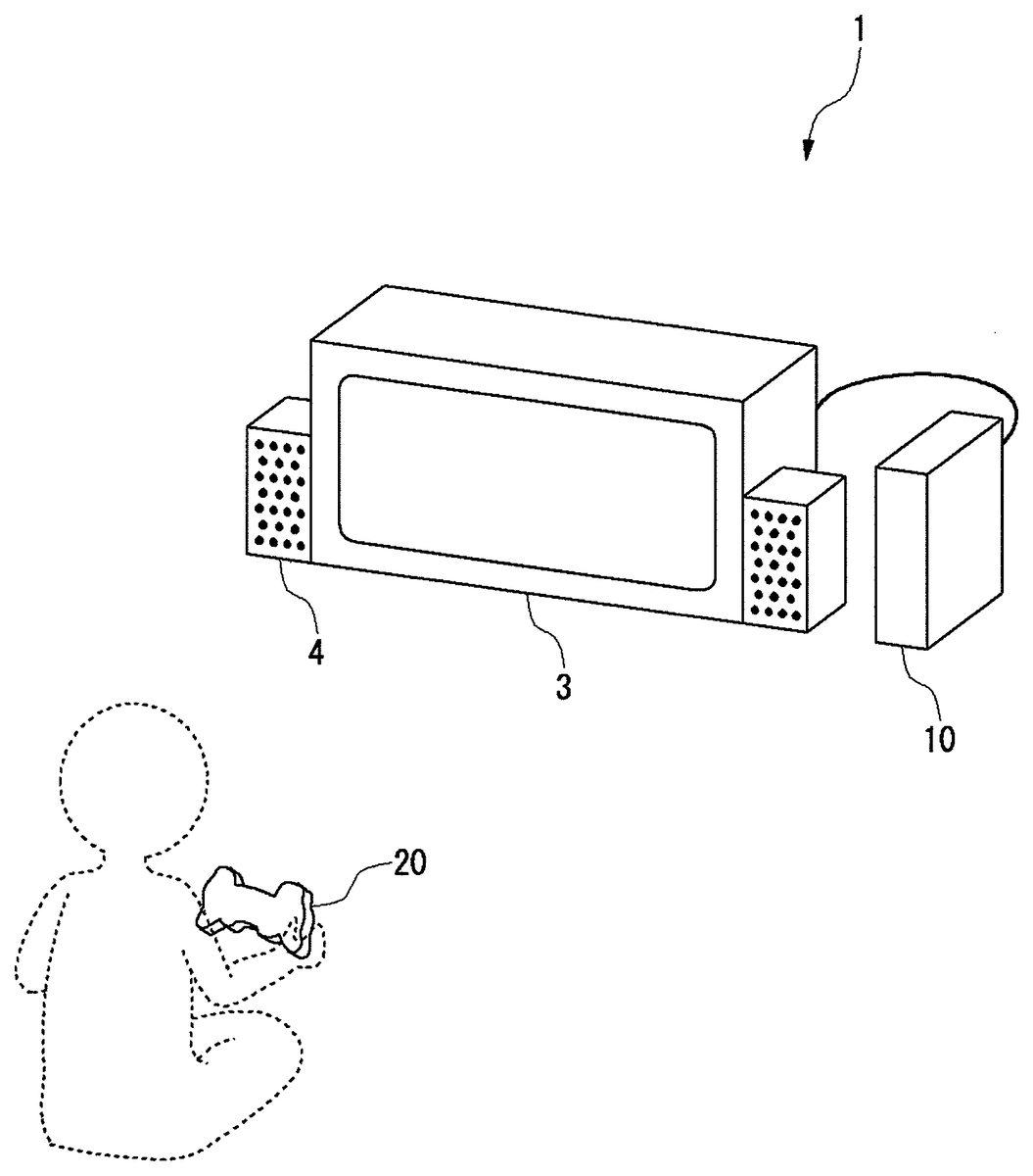
DETAILED DESCRIPTION OF THE INVENTION The invention will now be described by reference to the preferred embodiments. This does not intend to limit the scope of the present invention, but to exemplify the invention. FIG. 1shows the usage environment of a game system according to the embodiment of the present invention. A game system1is provided with an image display device3, an audio output device4, a game device10, and a controller20. The image display device3, the audio output device4, and the controller20are connected to the game device10. The image display device3is a display to process an image signal. The image display device3displays a game screen upon the reception of the image signal generated in the game device10. The audio output device4is a speaker to output audio. The audio output device4outputs game audio upon the reception of the audio signal generated in the game device10. The image display device3and the audio output device4constitute an output device in the game system1. The game device10and the output device may be connected via wires such as an AV cable or may be connected wirelessly. A home network built with, for example, a network (LAN) cable or a wireless LAN, may be established between the game device10and the output device. The controller20is an input device for a user to input game operation data to move a character in the game, and the game device10is a processing device which processes a game application based on the game operation data provided by the controller20and creates the image signal and audio signal indicating the processing result of the game application. The technique shown in the embodiment can be realized not only in game applications but in an entertainment system provided with a processing device to execute other kinds of applications. The game system1in which a game application is executed ...
DETAILED DESCRIPTION OF THE INVENTION
The invention will now be described by reference to the preferred embodiments. This does not intend to limit the scope of the present invention, but to exemplify the invention.
FIG. 1shows the usage environment of a game system according to the embodiment of the present invention. A game system1is provided with an image display device3, an audio output device4, a game device10, and a controller20. The image display device3, the audio output device4, and the controller20are connected to the game device10.
The image display device3is a display to process an image signal. The image display device3displays a game screen upon the reception of the image signal generated in the game device10. The audio output device4is a speaker to output audio. The audio output device4outputs game audio upon the reception of the audio signal generated in the game device10. The image display device3and the audio output device4constitute an output device in the game system1. The game device10and the output device may be connected via wires such as an AV cable or may be connected wirelessly. A home network built with, for example, a network (LAN) cable or a wireless LAN, may be established between the game device10and the output device.
The controller20is an input device for a user to input game operation data to move a character in the game, and the game device10is a processing device which processes a game application based on the game operation data provided by the controller20and creates the image signal and audio signal indicating the processing result of the game application. The technique shown in the embodiment can be realized not only in game applications but in an entertainment system provided with a processing device to execute other kinds of applications. The game system1in which a game application is executed will be explained as follows as a representation of entertainment systems.
The controller20has a function of transmitting the game operation data input by the user to the game device10, and in the embodiment, the controller20is provided as a wireless controller which communicates wirelessly with the game device10. The controller20and the game device10may establish a wireless connection by using Bluetooth (registered trademark) protocol. In transmitting and receiving the game operation data, the game device10functions as a base unit, in other words, a master, and the controller20functions as a slave unit, in other words, a slave. The controller20is not limited to a wireless controller and may be a wired controller which is connected to the game device10via a cable.
The controller20is activated by a battery which is not shown, and is provided with a plurality of buttons and keys for user manipulation to progress the game. When the user manipulates the button or the key of the controller20, the manipulation data is periodically transmitted to the game device10as the game operation data wirelessly. The controller20is provided with a three axis acceleration sensor which detects acceleration in three axes, and an angular velocity sensor which detects angular velocity around a predetermined axis. The three axis acceleration sensor and the angular velocity sensor constitute the motion sensor which detects the movement of the controller20. In some game applications, detection value of each sensor is treated as the game operation data and transmitted periodically to the game device10wirelessly. For example, by moving the controller20as if it were a steering wheel of a car, the output data of the three axis acceleration sensor and the angular velocity sensor are used as game operation data in a racing game where cars are moved in the game.
The game device10receives the game operation data on the game application from the controller20, controls the game progress in accordance with the game operation data, and generates the game image signal and the game audio signal. The generated game image signal and the game audio signal are output by the image display device3and the audio output device4, respectively. The game device10has a function of transmitting to the controller20the vibration control signal to vibrate the controller20in accordance with the progress status of the game application. The controller20has the vibrator, and upon the reception of a vibration starting signal, the controller20starts driving the vibrator; and upon the reception of a vibration terminating signal, the controller20terminates driving the vibrator. The game device10may transmit for every transmission frame a vibration controlling signal indicating whether to drive the vibrator; and in that case, the vibration of the controller20is controlled in accordance with the vibration controlling signal.
FIG. 2shows the exterior configuration of a controller. The controller20is provided with a direction key21, an analog stick27, and four different manipulation buttons26. The four different buttons22-25are marked with different figures in different colors so as to distinguish one button from another. More specifically, a ∘ button22is marked with a red circle, a x button23with a blue cross, a □ button24with a purple square, and a Δ button25with a green triangle.
The user grips a left grip part28awith his or her left hand, a right grip part28bwith his or her right hand, and manipulates the controller20. The direction key21, the analog stick27, and the manipulation buttons26are provided on a top housing30so that the user can manipulate them while gripping the left grip part28aand the right grip part28b.
The vibrators provided with, for example, motors, are placed inside of the housings of the left grip part28aand the right grip part28b. When a wireless communication module of the controller20receives the vibration starting signal from the game device10, the right and left vibrators are driven. The vibrating motion is then transmitted the housing of the controller20, and the controller20vibrates. Also a substrate for controlling the function of the controller20is placed near the center of the interior of the housing of the controller20. For example, the previously mentioned three axis acceleration sensor and the angular velocity sensor are installed on the substrate. The housing which constitutes the outer frame of the controller20is constituted by fitting a bottom housing and a top housing to each other, and a vibrator and a substrate are fixed to the bottom housing.
The three axis acceleration sensor and the angular velocity sensor on the substrate detect the movement of the controller20, and when the vibrator is driven, the vibration component of the controller20generated by driving the vibrator is included in the detection value. If the above mentioned racing game has a game setting in which a car runs straight by maintaining the controller20in a horizontal position, it is conceivable that the car which should run straight runs in zigzags due to the vibration component when the vibrator is driven. Since such behavior of the car gives the user unpleasant feeling, the vibration component from the vibrator is preferably removed to a maximum extent from the game operation data. The mechanism of reflecting the position and the movement of the controller20affected by the movement of the user in a character in the game the user is playing will be explained as precisely as possible as follows.
FIG. 3shows the internal configuration of a controller. The controller20has a processing unit90and is further provided with vibrators80aand80bwhich are provided with motors and eccentric members, and a wireless communication module92. The vibrators80aand80bare placed in the left grip part28aand right grip part28b, respectively in the inside of housing of the controller20. The wireless communication module92has a function of transmitting and receiving data to and from the wireless communication module of the game device10. The processing unit90performs the desired process in the controller20. The functions of the processing unit90and the wireless communication module92may be realized as a circuit built in a substrate provided inside of the housing.
The processing unit90is provided with a main controlling unit50, an input reception unit52, a sensor block56, a filter block60, an analog-to-digital conversion device64, an averaging processing block68, a memory70, a readout unit72, a communication controlling unit74, and a drive controlling unit76. The communication controlling unit74transmits and receives necessary data to and from the wireless communication module92.
The input reception unit52receives the manipulation data from an input unit, for example, the direction key21, the manipulation button26, and the analog stick27, and transmits the manipulation data to the main controlling unit50. The main controlling unit50provides the received manipulation data to the memory70and stores the manipulation data in the memory70. The manipulation data from various input units are overwritten in the respective area assigned for each manipulation data as game operation data in the memory70.
The communication controlling unit74controls the transmission process of the wireless communication module92at predetermined cycles. Since the frame cycle of a game image of the game device10is set at 1/60 s, the transmission cycle of the wireless communication module92is set at less than 1/60 s, for example, 11.25 ms. The readout unit72reads out game operation data from the memory70in accordance with the transmission cycle of the wireless communication module92, and provides the game operation data to the communication controlling unit74. Since the manipulation data from the various input units are overwritten and saved in the respective storage areas, the readout unit72can provide the manipulation data as the latest game operation data to the communication controlling unit74.
The sensor block56has a plurality of acceleration sensors54and angular velocity sensors53. When the sensor block56includes three axis acceleration sensor, the sensor block56is provided with three acceleration sensors54. The acceleration sensor54and the angular velocity sensor53detect the movement of the controller20caused by the movement of the user. The detection values, which are output data, of the acceleration sensor54and the angular velocity sensor53are used as the game operation data of a game application in the embodiment.
The filter block60has a plurality of low pass filters (LPF)58and57. LPF58is installed at the downstream of acceleration sensor54, and is a filter which passes the frequency component below the cutoff frequency of the output data of acceleration sensor54, and attenuates a frequency component close to or above the cutoff frequency. The LPF57is installed at the downstream of the angular velocity sensor53, and is a filter which passes the frequency component below the cutoff frequency of the output data of the angular velocity sensor53, and attenuates a frequency component close to or above the cutoff frequency. LPF58and LPF57may be constituted as passive filters and to have the same cutoff frequencies. Compared with an active filter, the passive filter does not require electricity for the filter operation; and thus, the passive filter is suitable for use in the battery driven controller20.
Although not shown in the figure, an additional passive filter may be installed between the acceleration sensor54and LPF58. The passive filter may be formed inside of the acceleration sensor54, or may be formed by the internal resistor of the acceleration sensor54and the condenser installed outside of the acceleration sensor54. Also, the passive filter may be formed outside of the acceleration sensor54so as to become in series with LPF58. The cutoff frequency of the passive filter is set higher than the cutoff frequency of LPF58.
Similarly not shown in the figure, an additional active filter may be installed between the angular velocity sensor53and LPF57. The active filter has an amplifying component, for example, an OP amp and a transistor, and has a function of amplifying the output data of the angular velocity sensor53and providing the amplified output data to LPF57. Since the output data of the angular velocity sensor53is smaller when compared with the output data of the acceleration sensor54, by amplifying with the active filter, the output data can be used preferably as the game operation data. The cutoff frequency of the active filter is set higher than the cutoff frequency of LPF57.
The analog-to-digital conversion device64is provided with a plurality of analog-to-digital converters (ADC)62and63. ADC62converts an analog signal output from the LPF58into a digital signal. The ADC63converts an analog signal output from the LPF57into a digital signal. Preferably, a sampling cycle is set smaller than the transmission cycle of the wireless communication module92. The sampling cycle may be, for example, about 2 ms. The analog-to-digital conversion device64may retain a fixed sampling cycle or allow the sampling cycle to be controlled as desired by the main controlling unit50.
The averaging processing block68is provided with a plurality of averaging processing units66and67. The averaging processing unit66performs the averaging process on sampling values output from ADC62during the transmission cycle of the wireless communication module92, and overwrites the averaged value as game operation data in the area assigned in the memory70. The averaging processing unit67performs the averaging process on sampling values output from the ADC63during the transmission cycle of the wireless communication module92, and overwrites the averaged value as game operation data in the area assigned in the memory70. As described above, the averaging processing units66and67can reduce the influence of the vibration component of the housing attributed to the vibrator80superimposed on the sensor output data by averaging the sampling values during the transmission cycle. The averaging processing units66and67do not need to exist in the processing unit90, and in that case, the sampling values of ADCs62and63are overwritten and stored as game operation data in the respective areas in the memory70at a sampling cycle.
As stated previously, the readout unit72reads out the game operation data from the memory70in accordance with the transmission time specified by the transmission cycle of the wireless communication module92, and provides the game operation data to the communication controlling unit74. Since the sensor output data provided by the averaging processing units66and67and the ADCs62and63are overwritten and saved in the respective storage areas, the readout unit72can provide the latest sensor output data, which is included in the game operation data, to the communication controlling unit74. The communication controlling unit74transmits, via the wireless communication module92and to the game device10, the sensor output data as the game operation data which is acquired by the motion sensor, more specifically, the acceleration sensor54and the angular velocity sensor53, along with the manipulation data of, for example, the manipulation button26which is received by the input reception unit52.
Upon the reception of a vibration controlling signal indicating the start or termination of the vibration from the game device10, the wireless communication module92provides the vibration controlling signal to the main controlling unit50. The main controlling unit50provides the vibration controlling signal to the drive controlling unit76, and the drive controlling unit76controls the drive of the vibrators80aand80bbased on the vibration controlling signal. The drive controlling unit76may be provided as a switch for driving the vibrators80aand80b, or as a PWM controlling unit for varying a duty ratio of a supply voltage.
FIG. 4shows the configuration of a low pass filter installed at the output of the acceleration sensor. The output data of the acceleration sensor54passes through a two-stage structured second-order passive filter59provided with LPF61and LPF58and is filter processed by the second-order passive filter59. The second-order passive filter59constitutes a two-stage low pass filter. The cutoff frequency of the second-order passive filter59is set as the smaller of the cutoff frequency of LPF61and the cutoff frequency of LPF58. As shown inFIG. 3, LPF58is positioned at the downstream of the output of the acceleration sensor54, and LPF61is positioned between the acceleration sensor54and LPF58. In the example ofFIG. 4, LPF61is provided with an internal resistor R1in the acceleration sensor54and a capacitor C1. LPF58is provided with a resistor R2and a capacitor C2. Although the order of the filter is not limited to the second order, the second order is preferred in the controller20as will herein after be described in detail.
The controller20in the embodiment has the vibrator80which vibrates, along with the acceleration sensor54and the angular velocity sensor53. In the motion sensor such as the acceleration sensor54, it is desirable that the movement of the controller20caused by movement of the user is accurately detected, and it is not desirable that the motion sensor detects the vibration component given to the housing due to the vibrating motion of the vibrator80. Usually, there is a limit to the speed at which the user moves the controller20. Therefore, by setting the cutoff frequency of the second-order passive filter59to a maximum frequency, which is considered to be a maximum frequency at which the user can move the controller20, or less, the vibration component of the controller20attributed to the vibrating motion of the vibrator80can be removed from the output data of the acceleration sensor54, while the acceleration sensor54can detect the movement of the controller20caused by the movement of the user.
As for the vibration component which affects the detected value by the motion sensor such as the acceleration sensor54, the resonance element attributed to the vibrating motion of the vibrator80is far larger than the vibration component of the vibrator80. Preferably, in the game device10in the embodiment, the peak value of the natural frequency of the controller20is set high by tightly fixing the member in the housing to the housing. In this case, the cutoff frequency of LPF58can be set lower than the peak value of the natural frequency of the controller20, at least a part of the resonance element can be removed in the second-order passive filter59. In this case, by setting the cutoff frequency of LPF58to two thirds or less of the peak value of the natural frequency of the controller20, the majority of resonance elements can be removed.
FIG. 5shows the configuration of a low pass filter installed at the output of the angular velocity sensor. The output data of the angular velocity sensor53passes through a two-stage structured second-order low pass filter44provided with LPF42and LPF57and is filter processed by the second-order low pass filter44. The cutoff frequency of the second-order low pass filter44is set as the smaller of the cutoff frequency of LPF42and the cutoff frequency of LPF57. As shown inFIG. 3, LPF57is positioned at the downstream of the output of the angular velocity sensor53, and LPF42is positioned between the angular velocity sensor53and LPF57. As stated previously, LPF42is constituted as an active filter in order to amplify the output data of the angular velocity sensor53. In the example ofFIG. 5, LPF42is provided with an internal resistor R3in the angular velocity sensor53, an OP amp, a resistor R4, and a capacitor C3. LPF57is provided with a resistor R5and a capacitor C4.
As explained in relation toFIG. 4, there is a limit to the speed at which the user moves the controller20. Therefore, by setting the cutoff frequency of the two-stage low pass filter44to the maximum frequency at which a person can move the controller20or less, the angular velocity sensor53can detect the movement of the controller20caused by the movement of the user, and the vibration component of the controller20attributed to the vibrating motion of the vibrator80can be removed from the output data of the angular velocity sensor53. In the game device10in the embodiment, by tightly fixing the member in the housing to the housing, the cutoff frequency of LPF57can be set lower than the peak value of the natural frequency of the controller20, and at least a part of the resonance element can be removed in the two-stage low pass filter44. In this case, by setting the cutoff frequency of LPF57to two thirds or less of the peak value of the natural frequency of the controller20, the majority of resonance elements can be removed.
FIG. 6Ashows the substrate and the vibrator which are fixed in the bottom housing being exposed after the removal of the top housing of the controller. A substrate88has a horizontally oriented shape, and is fixed to a front central position of the bottom housing. The vibrator80ais provided with a motor82aand an eccentric member86aattached at the end of the motor shaft, and is fixed to a position in the left grip part28aof the bottom housing while being sandwiched by a pair of binding lugs84a. Similarly, the vibrator80bis provided with a motor82band an eccentric member86b, and is fixed to a position in the right grip part28bof the bottom housing while being sandwiched by a pair of binding lugs84b. The eccentric member86has a semicircular shape and is eccentrically fixed to the motor shaft, and when the motor shaft rotates, the eccentric member86vibrates the housing.
FIG. 6Bshows the fixed structure of a motor. A pair of binding lugs extends from the bottom housing, and the motor82is pushed between the pair of binding lugs84. While the motor82is pushed in, the pair of binding lugs84has elasticity for pushing the motor82in the direction in which the pair of binding lugs becomes closer to each other, and the motor82is tightly fixed to the bottom housing by the elastic force. The substrate88is also tightly fixed to the bottom housing in order to raise the natural frequency.
FIG. 7shows the result of the experiment in which the relation is acquired of the vibration frequency of the controller and the noise level detected by the acceleration sensor. The output data of the acceleration sensor54is a detected value without filtering with the filters, such as LPF61or LPF58, in other words, the detected value for the acceleration sensor54is shown. According to the experimental result, the tendency is found in which the noise detected by the acceleration sensor54increases considerably when the vibrating frequency applied to the controller20is between 15 Hz and 20 Hz. Also, as shown in the figure, the peak value of the natural frequency (natural vibration frequency) of the controller20is approximately 22 Hz. Accordingly, the inventor found from the experimental result that in order to effectively remove the vibration component applied to the housing of the controller20, it is preferable the cutoff frequency of LPF58is set to 15 Hz or less.
In general, the frequency of vibration given to the controller20by the movement of the user is lower than the frequency given to the controller20by the vibrator80. As stated previously, there is a limit to the speed at which a person can move the controller20, and it is conceivable that the frequency of vibration given to the controller20does not usually exceed 15 Hz. Therefore, if the cutoff frequency of LPF58is set to a predetermined value of 15 Hz or less, for example to 15 Hz, LPF58can suitably output the vibration component attributed to the movement of the user and the vibration component attributed to the vibrating motion of the vibrator80can be removed effectively.
On the other hand, when the cutoff frequency of LPF58is lowered to a maximum extent within the range where the movement of the controller20caused by the movement of the user can be detected (e.g., about 5 Hz), the vibrating motion attributed to the vibrator80can be effectively removed; on the other hand, the lag time in LPF58becomes longer due to the effect of a time constant. In the game system1, the game operation data of the user is preferably reflected in the movement of the character in the game the user is playing instantaneously, and the lag time in LPF58is preferably reduced to a maximum extent. More specifically, the lag time is preferably set shorter than the transmission cycle of the wireless communication module92. In this case, by installing LPF58, the lag longer than two transmission cycles is not generated in the transmission of the sensor output data, and the maximum lag is one transmission cycle.
For example, the resistance of the resistor R2is set to 33 kΩ, and the capacitance of the capacitor C2is set to 0.33 μF. As described above, by setting the resistance and the capacitance, the cutoff frequency of a CR filter becomes about 15 Hz. In this case, the lag time due to the time constant is about 10.89 ms. As stated previously, when the transmission cycle of the wireless communication module92is set to 11.25 ms in the embodiment and the cutoff frequency is set to 15 Hz, the lag time of the LPF58becomes shorter than the transmission cycle of the wireless communication module92. As a result, even if LPF58is installed, the maximum transmission lag time for the sensor output data can be kept to one transmission cycle of the wireless communication module92.
Referring toFIG. 4, LPF61placed in the former stage of LPF58may have the same structure as the structure of LPF58so as to have the cutoff frequency of 15 Hz. In this case, the maximum transmission lag time caused by the second-order passive filter59can be kept to two transmission cycles of the wireless communication module92. Thus, the lag time which is acceptable in the game in which the real time performance is required can be realized.
Described above is the explanation on the LPF58installed at the output of the acceleration sensor54. For the same reason, the appropriate cutoff frequency, which allows for the lag time due to the time constant, is also set for the LPF57installed at the output of the angular velocity sensor53.
Referring toFIG. 5, LPF57may have the same structure as the structure of LPF58which has the cutoff frequency of 15 Hz. More specifically, the resistance of the resistor R5can be set to 33 kΩ, and the capacitance of the capacitor C4can be set to 0.33 μF. Also, as for LPF42placed in the former stage of LPF57, the resistance and the capacitance may be set to have the cutoff frequency of about 1 kHz. In this case, the maximum lag time caused by the second-order low pass filter44can be kept to two transmission cycles of the wireless communication module92. Thus, the lag time which is acceptable in the game in which the real time performance is required can be realized.
FIGS. 8A and 8Bshow the simulation result for LPF placed at the downstream of the acceleration sensor. In the simulation, the voltage level in the movable frequency band and the frequency characteristics in the noise frequency band are examined in the situations where the one or two LPFs are placed at the downstream of the acceleration sensor54as follows:
1) One LPF having 15 Hz cutoff frequency is installed.
2) Two LPFs having 15 Hz cutoff frequencies are installed in series.
3) One LPF having 7.5 Hz cutoff frequency is installed.
FIG. 8Ashows the voltage level in the movable frequency band. The simulation result revealed that the attenuation element of the sensor output data is considerably large in the situation where one LPF having 7.5 Hz cutoff frequency is installed.
FIG. 8Bshows the frequency characteristics in the noise frequency band. The simulation result revealed that the noise component cannot be suitably removed in the situation where one LPF having 15 Hz cutoff frequency is installed. InFIG. 8B, although the range from 10 Hz to 35 Hz is shown as the noise frequency band, the frequency of 15 Hz or higher is considered as the noise component in the environment in the embodiment.
According to the simulation result described above, by installing the second-order passive filter59provided with two LPFs, LPF61and LPF58, at the downstream of the acceleration sensor54, the second-order passive filter59can output the movement of the user suitably, and the vibration component attributed to the vibrating motion of the vibrator80can be suitably removed from the sensor output data. For the reason stated above, LPF61and LPF58having the cutoff frequency of 15 Hz are installed in two stages at the downstream of the acceleration sensor54in the embodiment.
FIG. 9shows a variation example of LPF. The LPF58is provided so that filter circuits58aor58bwhich have different cutoff frequencies can be used selectively by a switch55. Although LPF61shown inFIG. 4is installed between the acceleration sensor54and LPF58, the schematic illustration is omitted. In LPF58shown inFIG. 9, the filter circuit58amay, for example, have a cutoff frequency of 10 Hz, and the filter circuit58bmay have a cutoff frequency of 15 Hz. A bypassing route58cwhich bypasses filter circuits can also be selected with the switch55.
As stated above, since the lag is caused by the time constant in the filter circuit, the sensor output is preferably unconnected to the filter circuit from the lag time perspective in the game application where the immediate reflection of the game operation data of the user in the movement of the character in the game is required. In the game application where there is no vibrating motion of the vibrator80, the main controlling unit50controls the switch55so as to connect the acceleration sensor54and the bypassing route58c. In contrast, in the game application where vibrating motion of the vibrator80is generated, the main controlling unit50determines the destination for the acceleration sensor54according to whether the game application requires low latency. More specifically, in the game application where low latency is required, the main controlling unit50controls the switch55so as to connect the acceleration sensor54and the filter circuit58b; and in the game application where low latency is not required, the main controlling unit50controls the switch55so as to connect the acceleration sensor54and the filter circuit58a. Thus, by controlling the switch55with the main controlling unit50in accordance with the presence of vibrating motion generated and further of requirement for the low latency, the appropriate game operation data in accordance with the game application can be sent to the game device10.
The information indicating whether the vibrating motion is generated and whether the low latency is required in the game application may be sent beforehand to the controller20from the game device10. When the information indicating whether the vibrating motion is generated and/or whether the low latency is required is embedded in the game program, the game device10may read the information out and notify the controller20of the information beforehand. The main controlling unit50sets the connection destination of the switch55based on the notified information.
The driving of the vibrator80is controlled by the vibration controlling signal sent form the game device10. Therefore, upon the reception of the vibration starting signal, the main controlling unit50may switch the switch55from the bypassing route58cto the filter circuit58aor filter circuit58b, and upon the reception of the vibration terminating signal, the main controlling unit50may return the switch55back to the bypassing route58c. As a result, since the vibration component attributed to the vibrating motion of the vibrator80is filter processed while the vibrating motion of the vibrator80is generated, and the output of the acceleration sensor54is connected to the bypassing route58cwhile the vibrating motion of the vibrator80is not generated, the lag due to the filter processing can be avoided. Described above is the explanation on the LPF58installed at the downstream of the acceleration sensor54. LPF57installed at the downstream of the angular velocity sensor53may have the same configuration.
FIG. 10shows the configuration of a game device. The game device10is provided with a wireless communication module100, a communication controlling unit102, a main controlling unit104, a sensor output correction unit110, a vibration controlling signal creation unit120, an application processor130, and an output unit140. The processing functions according to the embodiment are implemented by any CPU, a memory or a program loaded into the memory. Configurations are implemented by the cooperation of hardware components. The program may be built in the game device10or may be provided from outside, being stored in the recording medium. Thus, a person skilled in the art should appreciate that there are many ways of accomplishing these functional blocks in various forms in accordance with the components of hardware only, software only, or the combination of both. In the illustrated example, the CPU of the game device10accomplishes the functions as the communication controlling unit102, the main controlling unit104, the sensor output correction unit110, the vibration controlling signal creation unit120, and the application processor130. The game device10may have a plurality of CPU's, considering the configuration of the hardware. In this case, a CPU may function as the communication controlling unit102which controls the function of the wireless communication module100, another CPU may function as the main controlling unit104which controls the function of the whole game device10, another CPU may function as the application processor130and the vibration controlling signal creation unit120, and another CPU may function as the sensor output correction unit110.
The communication controlling unit102transmits and receives the required data to and from the wireless communication module100, controls the communication process of the wireless communication module100, and the wireless communication module100establishes the wireless communication with the wireless communication module92of the controller20. The wireless communication module100and the wireless communication module92establish connections by, for example, a Bluetooth (registered trademark) protocol. The data such as the game operation data is sent at predetermined cycles from the wireless communication module92of the controller20, and the communication controlling unit102provides the data received by the wireless communication module100to the main controlling unit104.
The main controlling unit104provides the game operation data input through the input unit such as the direction key21to the application processor130. The application processor130reflects the game operation data in the process of the game application.
The main controlling unit104provides the digitalized sensor output data to the sensor output correction unit110. The game application started at the application processor130uses the sensor output data as game operation data, and the sensor output correction unit110corrects the sensor output data appropriately and provides the corrected sensor output data to the application processor130as game operation data. The application processor130reflects the sensor output data in the process of the game application.
Upon the reception of the sensor output data, a sensor output acquisition unit112provides the sensor output data to a masking processing unit118. The sensor output acquisition unit112may perform the averaging process on the sensor output data provided from the controller20at predetermined cycles and then provide the averaged sensor output data to the masking processing unit118. For example, the sensor output acquisition unit112performs the averaging process on the sensor output data of the predetermined number of cycles. As described above, the sensor output acquisition unit112can reduce the influence of the vibration component of the housing attributed to the vibrator80superimposed on the sensor output data by averaging the predetermined number of sensor output data provided in succession. The masking processing unit118performs the masking process on the acceleration sensor output data within the predetermined range of masking including zero acceleration. More specifically, the masking processing unit118corrects such acceleration sensor output data to have zero acceleration. There are a plurality of acceleration sensors54in the controller20and the same number of sensor output correction units110as the number of acceleration sensors54are provided. The masking processing unit118also performs the masking process on the angular velocity sensor output data within the predetermined range of masking including zero angular velocity. More specifically, the masking processing unit118corrects such angular velocity sensor output data to have zero angular velocity.
FIGS. 11A and 11Bshow the sensor output data of the detected motion of a controller caused by the movement of a user. For example, the sensor output data is the acceleration sensor output data of a z-axis element (vertical element).FIG. 11Ashows a sensor output data SO_10where the user grips the controller in a horizontal position without any vertical movements, andFIG. 11Bshows a sensor output data SO_20where the user grips the controller in a horizontal position and moves the controller up and down in a vertical direction.
FIGS. 12A and 12Bshow sensor output data of the detected vibrating motion of a controller, caused by the vibrating motion of a vibrator, along with the movement of a controller, caused by the movement of a user.FIG. 12Ashows a sensor output data SO_12where the user grips the controller in a horizontal position without any vertical movements, andFIG. 12Bshows a sensor output data SO_22where the user grips the controller in a horizontal position and moves the controller up and down in a vertical direction. Compared toFIGS. 11A and 11B,FIGS. 12A and 12Bshow the vibrating motions of the controller20attributed to the vibrating motions of the vibrator80are superimposed on the movements of the controller20caused by the movements of the user.
When the vibration component of the vibrator80is superimposed on the sensor output data and the sensor output data is used as the game operation data to move the game character, the behavior of the game character shown is unintended to the user with respect to the game input by the movement of the user. Thus, all the noise components attributed to the vibrating motion of the vibrator80are preferably removed in a normal situation.
However, the inventor has acquired a knowledge through the experiment using test subjects that there is a difference in the influence given to the user by the noise component attributed to the vibration motion of the vibrator80between when the user moves the controller20and when the user does not move the controller20. In this experiment, it was found out that the user has a tendency to have unpleasant feeling when the game character moves due to the noise component attributed to the vibrating motion of the vibrator80against the user's intension of making the game character to be stationary by not moving the controller20, on the other hand, the user barely notices the effect on the game character caused by the noise component attributed to the vibrating motion of the vibrator80when the user moves the controller20with intension of moving the game character. Through this experiment, the inventor came to the finding that since it was not easy to move the controller20accurately as desired, the noise component of an amplitude smaller than the movement of the user can be considered to be in the error range of the movement of the user.
Therefore, the sensor output data of SO_12shown inFIG. 12Ais undesirable because the game character moves against the intention of the user wanting to fix the movement of the game character, and on the other hand, it can be seen that the sensor output data of SO_22shown inFIG. 12Bcan achieve the movement of the game character without giving any unpleasant feelings to the user. The masking processing unit118in the embodiment corrects the sensor output data by performing the masking process on the amplitude component within the predetermined range including zero acceleration based on the above mentioned finding.
FIGS. 13A and 13Bshow the range of acceleration of masking.FIG. 13Ashows the relation between sensor output data SO_12and the range of masking, andFIG. 13Bshows the relation between sensor output data SO_22and the range of masking. The range of masking is set to −Ath or larger (Ath is a positive predetermined value) and to Ath or smaller, and an absolute value of a negative lower limit and a positive upper limit within the range of masking are equal. This is caused due to the noise component attributed to the vibrator80swings to almost evenly in the positive and negative based on the current posture of the controller20. An absolute value of a negative lower limit and a positive upper limit within the range of masking do not need to be always equal.
FIG. 14shows the relation of a sensor output data and acceleration during masking process. In this example, the sensor output data takes the value of FFh from 00h (hex), the sensor output data 00h corresponds to the acceleration of −3 G, and the sensor output data FFh corresponds to the acceleration of +3 G. For example, when a sensor output data 74h corresponds to the acceleration of −Ath and a sensor output data 8Ch corresponds to the acceleration of +Ath, the masking processing unit118corrects the acceleration to zero and outputs the zero acceleration when the sensor output data is in the range from 74h to 8Ch.
FIGS. 15A and 15Bshow the result of masking processing the sensor output data shown inFIGS. 13A and 13B.FIG. 15Ashows a sensor output data SO_14generated by masking processing the sensor output data SO_12, andFIG. 15Bshows a sensor output data SO_24generated by masking processing the sensor output data SO_22. The sensor output data SO_14inFIG. 15Aappropriately expresses the state of the controller20which is held stationary by the user by removing the acceleration element in the range of masking. On the other hand, the sensor output data SO_24inFIG. 15Bsubstantially expresses the movement of the controller20caused by the movement of the user even though the acceleration element in the range of masking is removed. Thus, the masking processing unit118can correct the sensor output data to the appropriate game operation data by performing the masking process on the predetermined acceleration element around zero acceleration and disregarding the acceleration element.
The masking processing unit118provides the corrected sensor output data to the application processor130as the game operation data. The application processor130creates the image signal and the audio signal which reflect the game operation data provided by the masking processing unit118in the movement of the game character along with the game operation data through, for example, the manipulation button26, directly provided from the main controlling unit104, and provides the image signal and the audio signal respectively to the image display device3and the audio output device4from the output unit140.
The masking processing unit118may determine whether to perform the masking process based on the movement state of the controller20. As described above, since the masking process is a process to set the acceleration element within the range of masking to be zero, when the user moves the controller20, the motion element is masked and discarded.
The movement state determination unit114determines the movement state of the controller20and based on the result of the determination, the execution of the masking process may be controlled. More specifically, the movement state determination unit114acquires the sensor output data from the sensor output acquisition unit112and determines whether the sensor output data continues taking the value within the range of masking in succession for a predetermined period of time. The determination time may be, for example, a few seconds. When the movement state determination unit114determines that the sensor output data continues taking the value within the range of masking for the predetermined period of time, the movement state determination unit114notifies the masking processing unit118of the determination result. Upon the reception of the determination result, the masking processing unit118starts performing the masking process on the sensor output data. When the movement state determination unit114determines that the sensor output data takes the value outside the range of masking, the movement state determination unit114notifies the masking processing unit118of the determination result. Upon the reception of the determination result, the masking processing unit118terminates performing the masking process on the sensor output data. As described above, having the movement state determination unit114monitor the movement state of the controller20, the masking processing unit118can perform the masking process at an appropriate time.
The movement state of the controller20may be determined by whether the vibrator80is vibrating. A vibration controlling signal creation unit120creates the vibration controlling signal by the instruction from the application processor130and provides the vibration controlling signal to the main controlling unit104. Upon the reception of the vibration controlling signal, the communication controlling unit102transmits the vibration controlling signal to the controller20from the wireless communication module100. As stated above, since the vibrator80of the controller20is controlled by the vibration controlling signal created by the vibration controlling signal creation unit120, the approach to determine the movement state of the controller20is also effective by using the control.
More specifically, a vibration state determination unit116receives the vibration controlling signal from the vibration controlling signal creation unit120. As a result, the vibration state determination unit116determines whether the vibrator80will start or terminate the vibration. Upon the reception of the vibration starting signal, the vibration state determination unit116determines that the vibrator80is in the state to vibrate and notifies the masking processing unit118of the determination result. Upon the reception of the notification, the masking processing unit118starts performing the masking process on the sensor output data. Upon the reception of the vibration terminating signal, the vibration state determination unit116determines that the vibrator80is in the state to terminate the vibration and notifies the masking processing unit118of the determination result. Upon the reception of the notification, the masking processing unit118terminates the masking process on the sensor output data. It takes a certain amount of time until the inertia rotation of the eccentric member86stops after the vibration terminating signal is provided to the controller20followed by the termination of the voltage application to the motor82. Therefore, taking the time required for the rotation of the eccentric member86to stop after the termination of the voltage application into consideration, the masking processing unit118may stop the masking process after the predetermined period after the reception of the notification. As described above, having the vibration state determination unit116determines whether the controller20is in the state to vibrate sympathetically with the vibrating motion of the vibrator80, the masking processing unit118can perform the masking process at an appropriate time.
In controlling the masking process using the movement state determination unit114and the vibration state determination unit116, the controlling can be done using the movement state determination unit114or the vibration state determination unit116alone. However, by combining the movement state determination unit114and the vibration state determination unit116, the masking process in which the movement state of the controller20is reflected can be achieved. When the masking process is controlled using the combination of the movement state determination unit114and the vibration state determination unit116, the masking process control based on the determination result of the vibration state by the vibration state determination unit116may be given priority over the masking process control based on the determination result of the movement state by the movement state determination unit114. Since the vibrating motion of the controller20attributed to the vibrating motion of the vibrator80is not generated if the vibrator80is not vibrating, better control of the masking process can be achieved by determining whether the vibrator80is vibrating.
Described above is an explanation based on the embodiments of the present invention. These embodiments are intended to be illustrative only and it will be obvious to those skilled in the art that various modifications to constituting elements and processes could be developed and that such modifications are also within the scope of the present invention. In the embodiments, the example of performing the masking process on the acceleration sensor output data is explained. By performing the masking process on the angular velocity sensor output data in the same way, the vibration component of the controller20attributed to the vibrating motion of the vibrator80can be removed or reduced from the angular velocity sensor.
In the embodiment, the game device10has the function of correcting the sensor output data. However, the function of correcting the sensor output data may be realized by the controller20. For example, by placing the masking processing unit118in the subsequent stage of the analog-to-digital conversion device64or the averaging processing block68in the controller20, the controller20can have the function of correcting the sensor output data. In this case, the functions of the movement state determination unit114and the vibration state determination unit116can be realized by the main controlling unit50.
Claims
- A game controller operative to transmit game operation data to a game device, comprising: a housing;a motion sensor operative to detect a movement of the game controller;a low pass filter installed at an output of the motion sensor;and at least one vibrator which is driven by a vibration controlling signal sent from the game device, wherein the motion sensor, the low pass filter and the at least one vibrator are placed inside the housing, the at least one vibrator being fixed to the housing, a cutoff frequency of the low pass filter is set lower than a natural vibration frequency of the game controller, wherein the cutoff frequency of the low pass filter is set so that at least a part of a vibration component of the housing attributed to a vibrating motion of the vibrator can be removed, while the movement of the controller caused by a movement of a user can be output from the low pass filter, and wherein the cutoff frequency of the low pass filter is set with reference to a duration of transmission cycle of game operation data.
- The game controller according to claim 1 , wherein the cutoff frequency of the low pass filter is set to two thirds or less of a peak value of the natural vibration frequency of the game controller.
- The game controller according to claim 1 , wherein the low pass filter is configured so that filter circuits which have different cutoff frequencies can be selectively used.
- The game controller according to claim 1 , wherein the natural vibration frequency of the game controller is approximately 22 Hz and the cutoff frequency of the low pass filter is set to a predetermined value of 15 Hz or less.
- The game controller according to claim 1 , further comprising: a wireless communication module operative to transmit an output data of the motion sensor at a predetermined cycle, wherein a lag time caused by the low pass filter is set shorter than twice a duration of transmission cycle of the wireless communication module.
- The game controller according to claim 5 wherein the lag time caused by the low pass filter is set shorter than the duration of transmission cycle of the wireless communication module.
- The game controller according to claim 1 , further comprising;a wireless communication module operative to transmit an output data of the motion sensor at a predetermined cycle;another low pass filter installed between the motion sensor and the low pass filter, wherein a lag time caused by the low pass filters in two stages is set shorter than twice a duration of transmission cycle of the wireless communication module.
- The game controller according to claim 7 wherein the lag time caused by each of the low pass filters which constitute a two-stage low pass filter is set shorter than the duration of transmission cycle of the wireless communication module.
- The game controller according to claim 1 , wherein the motion sensor includes at least one acceleration sensor and an angular velocity sensor, further comprising: a passive filter installed between the acceleration sensor and the low pass filter;and an active filter installed between the angular velocity sensor and the low pass filter.
Disclaimer: Data collected from the USPTO and may be malformed, incomplete, and/or otherwise inaccurate.