U.S. Pat. No. 9,174,121
VIDEO GAME CONTROLLER CHARGING SYSTEM HAVING A DOCKING STRUCTURE
AssigneeNYKO TECHNOLOGIES, INC.
Issue DateJanuary 17, 2014
Illustrative Figure
Abstract
A video game controller charging system is provided. The video game controller charging system includes a base; at least one structure on the base for providing physical support to at least one video game controller while it is being charged; and at least one DC port on the base configured to couple to and provide DC power to a power input port of the at least one video game controller. The video game controller charging system may also include a current detector, a charging status indicator, at least one docking bay, and/or an AC-to-DC converter adapted to convert externally supplied power to the DC power provided to the power input port of at least one video game controller. The base of a charging station may include a recess having at least one electrical contact and a power input for connection to a power supply.
Description
DETAILED DESCRIPTION In one embodiment, a video game controller charging system is provided. The video game controller charging system includes a base, at least one structure on the base for providing physical support to at least one video game controller while it is being charged, and at least one DC port on the base configured to couple to and provide DC power to a power input port of the at least one video game controller. In some embodiments, the video game controller charging system may include a current detector, a charging status indicator, at least one docking bay, and/or an AC-to-DC converter adapted to convert externally supplied power to the DC power provided to the power input port of at least one video game controller. In other embodiments, the base of a charging system (or “charging station”) may include a recess having at least one electrical contact and a power input for connection to a power supply, the power input being electrically coupled to the at least one electrical contact. The charging station also includes an external adapter with a connector configured to couple to a power input port of the accessory device, and with at least one electrical lead. The recess is dimensioned to receive the adapter, with the at least one electrical lead contacting the at least one electrical contact when the adapter is received by the recess. In another embodiment, a power adapter includes a housing body having a plurality of sides. In addition, the power adapter includes a plug located on one side of the housing body and adapted to connect to an alternating current (AC) outlet. Furthermore, the power adapter includes first and second direct current (DC) ports, each located on a side of the housing body and each adapted to provide a DC power ...
DETAILED DESCRIPTION
In one embodiment, a video game controller charging system is provided. The video game controller charging system includes a base, at least one structure on the base for providing physical support to at least one video game controller while it is being charged, and at least one DC port on the base configured to couple to and provide DC power to a power input port of the at least one video game controller. In some embodiments, the video game controller charging system may include a current detector, a charging status indicator, at least one docking bay, and/or an AC-to-DC converter adapted to convert externally supplied power to the DC power provided to the power input port of at least one video game controller. In other embodiments, the base of a charging system (or “charging station”) may include a recess having at least one electrical contact and a power input for connection to a power supply, the power input being electrically coupled to the at least one electrical contact. The charging station also includes an external adapter with a connector configured to couple to a power input port of the accessory device, and with at least one electrical lead. The recess is dimensioned to receive the adapter, with the at least one electrical lead contacting the at least one electrical contact when the adapter is received by the recess.
In another embodiment, a power adapter includes a housing body having a plurality of sides. In addition, the power adapter includes a plug located on one side of the housing body and adapted to connect to an alternating current (AC) outlet. Furthermore, the power adapter includes first and second direct current (DC) ports, each located on a side of the housing body and each adapted to provide a DC power to an external device. Finally, the power adapter includes an AC-to-DC converter for converting the AC power received through the plug to the DC powers supplied to external devices.
A power adapter may include one or more USB ports to which devices with USB plugs can be connected for recharging. The adapter may also include one or more FireWire ports to which devices with FireWire plugs can be connected for recharging. Both ports may be operated concurrently. The adapter also has an AC plug that is fixed or is movable between a first position (e.g., operating position) and a second position (e.g., non-operating position). By way of example, the AC plug may extend from the rear side of the adapter. The AC plug can be fixed to the adapter housing body, or it can be retracted, folded, slid, or somehow moved into the adapter housing body for easy storage when the adapter is not in use. When the adapter is in use, the AC plug is plugged into an AC outlet. In one embodiment, the adapter draws AC power from the outlet, converts it to DC powers having +5 V and +13 V, respectively, and supplies the DC powers to the USB and FireWire devices, respectively, to enable them to recharge.
In each of the disclosed embodiments, the USB, FireWire, serial, parallel, and generally DC ports, may be either male or female. That is, the DC charging ports may be female and accept a plug, or may itself be a port plug for plugging into a port in an external device.
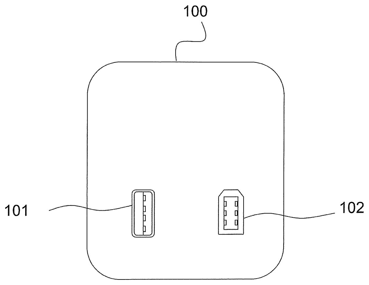
FIG. 1is a schematic front view diagram of a power adapter100in an exemplary embodiment of the present invention. The power adapter100has a USB port101to which a device with a USB plug can be connected for recharging. The power adapter100also has a FireWire port102to which a device with a FireWire plug can be connected for recharging. The power adapter100includes an AC-to-DC power converter for providing +5 V and +13 V, respectively. The power adapter100may take an input of 100 V to 240 V (w/frequencies of 50 Hz or 60 Hz) AC power and/or any other standard AC outlet voltage to enable the power adapter100to be used in a number of different countries throughout the world.
In the United States, AC voltage is standardized at 120 V, but in practice voltages range from 105 V to 130 V. In other parts of the world, voltages range from 100 V to 240 V. The frequencies vary across the world as well. In the U.S., 60 Hz is the standard. However, in other parts of the world, AC voltage is supplied at 50 Hz or 60 Hz. The AC-to-DC power converters in the power adapter may be adapted to convert AC voltages from a particular standard to a DC voltage required of the DC ports in the power adapter.
The USB port101is capable of delivering DC power having +5 V to a connected USB device. The FireWire port101is capable of delivering DC power having +13 V to a connected FireWire device. Ports101,102may be operated concurrently to recharge a USB device and a FireWire device at the same time. WhileFIG. 1illustrates that ports101,102are located at the front surface of the power adapter100, the ports may be located at any suitable location on the front, rear, side, top, or bottom surfaces or sides of the adapter100.
FIG. 2is a schematic front view diagram of a power adapter110in another exemplary embodiment of the present invention. The power adapter110has two FireWire ports102to which a device with a FireWire plug can be connected for recharging. The FireWire ports102may be of a different type and may accept 4-pin or 6-pin FireWire connections. Each FireWire port102is capable of delivering DC power having +13 V to a connected FireWire device. Ports102may be operated concurrently to recharge FireWire devices at the same time.
FIG. 3is a schematic front view diagram of a power adapter120in yet another exemplary embodiment of the present invention. The power adapter120has two USB ports101to which a device with a USB plug can be connected for recharging. The USB ports101may be of a different type and may accept type A or type B connections. Each USB port101is capable of delivering DC power having +5 V to a connected USB device. Ports101may be operated concurrently to recharge USB devices at the same time.
FIG. 4is a schematic front view diagram of a power adapter130in another exemplary embodiment of the present invention. Power adapter130has a USB port161and a FireWire port162that are connected to lines163. The lines extend the ports so that USB and FireWire plugs may be inserted into the extended ports without having to reach the power adapter130plugged into an AC outlet. Although a USB and FireWire port are shown inFIG. 4, this embodiment includes all possible combinations of ports, the combination being formed from USB, FireWire, serial, parallel ports, and other DC charging ports, in various combinations.
FIG. 5is a schematic side view diagram of the power adapter100ofFIG. 1in its non-operating position. The power adapters110and120ofFIGS. 2 and 3have substantially the same structure in one embodiment. As shown inFIG. 5, the power adapter100may have an AC plug103that is movable such that it extends from the rear side of the adapter100. In the non-operating position, when the adapter100is not in use, the AC plug103is slid, moved, or otherwise positioned into the adapter100so that the plug103does not extend out from the adapter100. This non-operating position allows for easy storage of the adapter100. In other embodiments, the plug may be fixed to the adapter housing body and is not movable.
FIG. 6is a schematic side view diagram of the power adapter100ofFIG. 1in its operating position. As shown inFIG. 6, when the power adapter100is in use, the AC plug103is slid, moved, or otherwise positioned outside of the housing of the adapter100, so that the plug103extends out from the adapter100in its operating position. In this position the AC plug103may be plugged into an AC outlet so that the adapter100can draw AC power from the outlet, convert it to DC powers having +5V and +13V, respectively, and supply the DC powers to hand-held and portable electronic devices.
While the AC plug103of the power adapter100illustrated inFIGS. 5 and 6appears as a pair of parallel flat bars that are commonly used in the United States and some other countries, for international use, the AC plug may have a shape of a pair of cylindrical bars used in many Asian and European countries, and/or any other suitable shape. Furthermore, a single power adapter may include a number of different types of AC plugs for use in many different countries having different AC plug types/AC power voltages.
FIG. 7is a conceptual diagram of a side view of an adapter100and an electronic device105in an exemplary embodiment of the present invention. The adapter100is plugged into an AC outlet106. A device105is connected to the adapter100by a cable104. The cable104plugs into the adapter100through a plug101or102, shown inFIG. 1. The adapter100draws power from the AC outlet106and delivers the power to the device105through the cable104.
FIG. 8is a diagram showing the AC-to-DC converter in the adapter100. The AC-to-DC converter112is located in the housing body of the adapter100. The AC-to-DC converter112receives an AC power from the AC plug103via an AC outlet106and provides DC power to a plurality of DC ports111. The AC-to-DC converter112may be composed of multiple AC-to-DC converters in order to provide different DC power voltages to the DC ports111. For example, inFIG. 1, the AC-to-DC converter would receive AC power from the AC plug103and provide DC 5 V to one DC port (e.g., USB port101) and DC 13 V to another DC port (e.g., FireWire port102).
FIG. 9is a schematic front view diagram of a power adapter200in another exemplary embodiment of the present invention. The adapter200has a plurality of USB ports201to which a plurality of devices with USB plugs can be connected for recharging. The USB ports201may be of various sizes to accommodate devices having different types of USB plugs (e.g., USB plugs of type A or type B). The adapter200also has a plurality of FireWire ports202to which a plurality of devices with FireWire plugs can be connected for recharging. The FireWire ports202may likewise be of various sizes to accommodate devices having different types of FireWire plugs (e.g., 6-pin or 4-pin FireWire plugs). The ports201and202may be located at any suitable location on the front, rear, side, top, or bottom surfaces or sides of the adapter200.
FIG. 10is a schematic front view diagram of a power adapter300in yet another exemplary embodiment of the present invention. The adapter300has a plurality of ports301a,301b,301c,301d,301e,301f,301ghaving different cross-sectional shapes to which a plurality of devices can be connected for recharging. The ports301may be any of a wide variety of ports used by popular electronic devices, such as USB, FireWire, PS/2, serial ports, parallel ports, and others. The ports301a-301gmay be located at any suitable location, on the front, rear, side, top, or bottom surfaces or sides of the adapter300. The ports of the power adapter300may have cross-sections that are different from the cross-sections of the ports301a-301gthat are shown for illustrative purposes only.
Similar to the power adapter100ofFIG. 1, the power adapters200and300ofFIGS. 9 and 10each have one or more AC plugs for plugging to corresponding AC outlets to receive AC power therefrom. The AC plugs may have different shapes to be compatible with AC outlets used in various different countries of the world.
Further, similar to the power adapter100, the power adapters200and300ofFIGS. 9 and 10may have capabilities to convert a range of different AC voltages that are used throughout the world. By way of example, the power adapters200and300may be able to convert from AC power having a voltage range of 100V to 240V (and at frequencies 50 Hz or 60 Hz) to DC power having +5 V and +13 V and/or any other desirable voltages.
FIGS. 11,12, and13are perspective, top, and side views, respectively, of a video game controller charging system400according to another exemplary embodiment of the present invention.FIG. 14is a perspective view of the video game controller charging system400having video game controllers420connected for charging. In one embodiment, the charging system400converts AC power from an AC power supply to DC power and supplying the DC power having a desired DC voltage to a connected CED accessory device, such as one of the video game controllers420. In such an embodiment, the video game controller charging system400includes an AC-to-DC converter for converting AC power to DC power. In other embodiments, the video game controller charging system400may receive DC power from an external power source. In such cases, the external DC power may be provided by an external AC-to-DC converter that receives power from an AC outlet, and converts the received AC power to DC power.
The video game controller charging system400includes a base402and one or more docking bays404, wherein each docking bay404is configured to receive a video game controller420. The charging system400also includes one or more partitions406separating the docking bays404. The charging system400further includes a DC port408within each of the docking bays404that is configured to electrically couple to one of the video game controllers420and deliver DC power to the coupled video game controller420.
The DC ports408of the video game controller charging system400are configured to connect to a power input port of the video game controller420to be charged. In the present embodiment, the DC ports408are male mini-USB (universal serial bus) connectors adapted to connect to a female mini-USB connector on a video game controller for a video game console, such as the PlayStation3®. Alternatively, the DC ports408may be any electrical connectors suitable for coupling to a video game controller for another video game console, or for any other consumer electronics device to be charged, such as an MP3 player or accessory device.
In the present embodiment of the video game controller charging system400, the partitions406include locators410for aligning the video game controller to the DC port408. There are locators410on each of the two surfaces of the partitions406, as well as the two surfaces of the base402, which face the DC ports408. There may be two locators410on each surface described, i.e., four locators410adjacent each video game controller420. Each pair of opposite surfaces, a portion of the base402, a corresponding docking bay404, and/or the locators410may comprise a structure for providing physical support to one of the video game controllers420during charging. While the locators410in the illustrated embodiment ofFIG. 11are button-shaped, the shape of the locators410is not limited thereto. Also, the locators410may be spring-loaded in order to facilitate aligning and maintaining a required position of the video game controller420for coupling to the corresponding DC port408. In other embodiments, the locators410may not be spring-loaded and the video game controller420may be aligned by the locators410through any other suitable method or mechanism, such as a pressure fit.
In use, the DC ports408are connected to power input ports of the video game controllers420to be charged, as shown inFIG. 14. When one or more video game controllers420need to be recharged, connecting the video game controllers420to the charging system400is as easy as inserting each of the video game controllers420into one of the docking bays404. As described above, the locators410aid in aligning the video game controller420into the docking bay404such that the power input port of the video game controller420slides down onto and connects to the DC port408. The charging system400is connected to a power supply through its own power input (either AC power which is converted to DC power using an internal AC-to-DC converter or externally provided DC power). The charging system400then provides power to the video game controller420to recharge the batteries of the video game controller420.
While the embodiment described above uses a vertical orientation, with each of the video game controllers420being dropped from above into the docking bays404, other orientations may be used as well. In one alternative embodiment, for example, the video game controllers420may be received horizontally into the docking bays404, and electrically coupled to DC ports408having a horizontal orientation instead of the vertical orientation shown inFIGS. 11-14.
The present embodiment of the video game controller charging system400can charge up to four video game controllers420concurrently, or it can charge one at a time. Alternative embodiments of the charging system400, however, may be configured to charge more than four video game controllers420concurrently. The power supply for the charging system400may be a power cord416that has a plug for connecting to an AC power supply or a DC power supply. In one embodiment, the charging system400also includes an AC-to-DC converter440(seeFIG. 15) electrically coupled between the power cord416and the DC ports408for converting AC power to DC power having +5 V or any DC voltage suitable for delivery to the video game controller420. The AC-to-DC converter440may be in the base402or external to the base402. The power cord416may be removably connected to the base402, or may be fixedly coupled to the base402. In an alternative embodiment, the power input may be a USB port that connects to a CED (e.g., a video game console) to obtain DC power from the CED. The charging system400provides this DC power to the DC ports408for delivery to the video game controllers420. In other embodiments, DC power may be provided as input to the charging system400, where the DC power may be provided by an external AC-to-DC converter. In such embodiments, the power input may be DC power converted from AC power from a wall outlet and converted to DC power using the external AC-to-DC converter.
The video game controller charging system400may also include an indicator panel450that indicates a status of the charging system400. In the present embodiment, the indicator panel450includes four LED assemblies452. Each of the four LED assemblies452corresponds with one of the four DC ports408, so as to indicate the charging status of the video game controller420being charged at the respective DC port408. Each of the LED assemblies452includes at least two LEDs having different colors. For example, each of the LED assemblies452in the present embodiment includes a red LED and a green LED. While the respective video game controller420is being charged, the red LED is emitted to indicate that the video game controller420, or more specifically, the battery inside the video game controller420, is currently being charged. When the respective video game controller420is finished charging, the green LED is emitted to indicate that the charging has been completed. In another embodiment, the green LED may be emitted to indicate that the video game controller is being charged, while the red LED is emitted to indicate that the charging has been completed. In alternative embodiments, each of the LED assemblies452may include different colors of LEDs and/or different numbers of LEDs (e.g., three LEDs) to indicate respective charging status.
In another alternative embodiment, each of the LED assemblies452may include a single LED and may illuminate with a first color (e.g., red) to indicate that the charging system400is currently charging a video game controller420. Another LED assembly452may illuminate with a second color (e.g., green) to indicate that the charging system400has completed charging. The LED assemblies may be electrically coupled to a current detector460(seeFIG. 15) which provides the signals to illuminate the LEDs. In one embodiment, the charging system400may stop providing power to the video game controller420when the video game controller's internal battery is completely charged.
FIG. 15is a block diagram showing some of the above-described components of the video game controller charging system400in schematic form. As can be seen inFIG. 15, the charging system400includes DC ports408, each of which is configured to be electrically coupled with a video game controller420. Through the DC ports408, the charging system400is capable of supplying the power received from a power adapter or a power supply to the video game controllers420for charging.
In one embodiment, the base402includes an AC-to-DC converter440for converting input AC power to DC power for charging the video game controller420. In other embodiments, the charging system400may be provided with an external AC/DC converter, DC power via a mini-USB port, or any other suitable DC power supply. The charging system400may include a USB host used to provide DC power via a mini-USB port.
In one embodiment, the video game controller charging system400includes one or more current detectors460for detecting the amount of current being provided by the power supply to the video game controllers420through the DC ports408. If sufficient current, i.e. a predetermined amount of current, is detected by one of the current detectors460, the corresponding LED (e.g., a red LED) is emitted to indicate that the video game controller420in the corresponding docking bay404is being charged. Then, when the charging has been completed, less current is detected because the battery in the accessory device is already substantially fully charged. In this case, another LED (e.g., a green LED) is emitted to indicate that charging has been completed.
Another exemplary embodiment of the invention, shown inFIGS. 16-23, relates to a charging station for a consumer electronics device (CED), and more particularly, to a charging station for one or more hand-held controllers for a video game console. A charging station510according to an exemplary embodiment of the invention is shown inFIG. 16. The charging station510includes two docking bays512,514for two accessory devices, which in one embodiment are hand-held controllers for a video game console. The docking bays512,514are dimensioned to accept adapters516(seeFIG. 17). Electrical contacts520in the docking bays512,514make contact with electrical leads522on the adapters516(seeFIG. 19B) to provide an electrical connection through which power can be transmitted. The adapters516are electrically coupled to the power input port on the hand-held controllers. In one embodiment, the adapters516drop-fit easily into the docking bays512,514, thus providing a fast and easy connection of the hand-held controllers to the charging station510.
As shown inFIG. 16, the charging station510includes a base524with two docking bays512,514. The docking bays512,514are each dimensioned to accept a hand-held controller526(seeFIGS. 20,21). The two docking bays512,514are separated by a partition528positioned between them. Each of the docking bays512,514includes a recess530at the bottom of the docking bay. The recess530has four electrical contacts520positioned in the recess530. In other embodiments, the recess may include more than four or less than four electrical contacts. These contacts520are shown positioned in a linear arrangement in the recess530, but they could be positioned in any suitable arrangement.
The recesses530are dimensioned to receive an adapter516into the recess530. As shown inFIG. 17, the adapters516can be dropped vertically into the docking bays512,514and into the recesses530. When the adapters516are placed into the recesses530, electrical leads522(seeFIG. 19B) on the bottom side538of the adapters516contact the electrical contacts520in the recesses530. The electrical leads522on the adapter516thus make an electrical connection with the electrical contacts520in the recess530. The electrical leads522on the adapter516match the arrangement of the electrical contacts520such that each electrical lead522makes physical contact with an electrical contact520when the adapter516is placed in the recess530. In one embodiment, as will be described later, the electrical contacts520are spring loaded so as to make sufficient contacts with the electrical leads522.
In other embodiments, the adapters516and the docking bays512,514have matching shapes, such as, for example, a molded male and female matching shape, which is not limited to the recess530described above. The docking bays512,514and the adapters516can have any suitable shapes that allow the electrical contacts520of the docking bays512,514to make contact with the electrical leads522of the adapters516. Thus, many molded configurations, including ridges, grooves, and other shapes, can be used to enable the docking bays512,514to receive the adapters516. These examples are illustrative only, and not limiting.
As shown inFIG. 18, in one embodiment, the adapters516and recesses530are shaped such that the adapter516can only be placed into the recess530in one orientation. In the embodiment shown, the adapter516includes at least one angled edge532, and the recess530includes a matching angled corner534. This geometry ensures that the adapter516will be placed in the recess530in the proper orientation, so that the electrical contacts520meet the electrical leads522. Other geometric configurations or features could be used to accomplish this function, such as matching prongs and recesses, or other types of shaped edges. Additionally, this feature is optional, as the adapter516could be made to fit into the recess530in multiple orientations.
As shown inFIGS. 19A-19C, the adapter516includes a body536with the angled edge532. The electrical leads522are located on a bottom side538of the body536. The top side540of the body536includes a connector542that is configured to connect to the power input port of the accessory device to be charged. In one embodiment, the connector542is a male mini-USB (universal serial bus) connector adapted to connect to a female mini-USB connector on a hand-held controller for a video game console, such as the PlayStation3®.
In use, the connector542on the adapter516is connected to the power input port of the accessory device to be charged, such as the hand-held controller526shown inFIGS. 20 and 21. The adapter516is a small and light-weight piece that connects snugly to the power input port of the hand-held controller526. The adapter516can remain with the hand-held controller526at all times, even when the controller526is not being charged in the charging station510. When the hand-held controller526is in use during operation of a video game, when the controller526is stored, and when it is charging, the adapter516can remain connected to (and physically mounted on) the controller526. The adapter516is small and light weight, so that it does not interfere with operation of the controller526. When the controller526needs to be recharged, connecting it to the charging station510is as easy as dropping it into one of the docking bays512,514. The adapter516slides easily into the recess530, and the electrical leads522on the bottom of the adapter516make an electrical connection with the electrical contacts520in the recess530. The charging station510is connected to a power supply through its own power input. The charging station510then provides power to the controller526to recharge the controller's batteries. This recharging process is fast and easy, as the adapter516allows the controller526to be simply dropped into place, rather than carefully connected to a fragile port or connector.
While the embodiment described above uses a vertical orientation, with the controller526and adapter516being dropped from above into the recess530, other orientations may be used as well. In one embodiment, the adapter516is received horizontally into one of the docking bays512,514, and the electrical contacts520in the docking bay and electrical leads522on the adapter516are arranged vertically to make contact with each other when the adapter516is horizontally placed into the docking bay. In one embodiment, the adapter516is placed into the docking bay by a push-fit, press-fit, or snap-fit, rather than simply a drop-fit. These fitting engagements are fast and easy to use, and also provide a reliable connection between the adapter516and charging station. In another embodiment, the charging station includes prongs that hold the controller and adapter into place after they have been placed (vertically or horizontally) into the docking bay to obtain a complete electrical connection.
The charging station510can charge two controllers526simultaneously (or concurrently), or it can charge one at a time. The power input for the charging station510may be a power cord544, as shown inFIG. 20, that connects to an alternating current (AC) power supply. In this case, the charging station510includes an AC/DC converter electrically coupled between the power input and the electrical contacts520, in order to provide direct current power to the contacts520and from there to the controllers526. The AC/DC converter546may be internal to the base524or external. In another embodiment, the power input is a USB port that connects to the CED to obtain DC power from the CED. The charging station provides this DC power to the electrical contacts520and from there to the controllers526. In other embodiments, DC power may be provided as input to the charging station510, where the DC power may be provided by an external AC/DC converter.
The electrical contacts520may include a spring coupling the contacts520to the base524. The weight of the controller526pushes the adapter516down into the recess530, pressing the electrical leads522on the adapter516against the electrical contacts520. The spring pushes back up on the contacts520, pushing them against the electrical leads522to ensure a complete electrical connection.
The charging station510may also include an indicator548that indicates a status of the charging station510. In one embodiment, the indicator548includes two LED assemblies550,552(seeFIG. 16). The LED assemblies550,552correspond with the first and second docking bays512,514, respectively, so as to indicate the charging status of the hand-held controller526(or any other suitable accessory device) being charged in the respective docking bay. Each of the LED assemblies550and552includes at least two LEDs having different colors. By way of example, each of the LED assemblies550and552in one embodiment includes a red LED and a green LED. While the respective hand-held controller526is being charged, the red LED is emitted to indicate that the hand-held controller526(i.e., the battery inside the hand-held controller526) is currently being charged. Further, when the respective hand-held controller526is finished charging, the green LED is emitted to indicate that the charging has been completed. In other embodiments, each of the LED assemblies550,552may include different color LEDs and/or different number (e.g., three) of LEDs to indicate respective charging status.
In still other embodiments, each of the LED assemblies550,552may include a single LED, and may be referred to as LEDs550,552. The first LED550illuminates with a first color, for example red, to indicate that the charging station510is currently charging an accessory device. The second LED552illuminates with a second color, for example green, to indicate that the charging station510is finished charging. The LEDs550,552may be electrically coupled to a current detector521(seeFIG. 22) which provides the signals to illuminate the LEDs. In one embodiment, the charging station510stops providing power to the controller526when the controller's internal battery is completely charged.
A block diagram of the charging station510is shown inFIG. 22, showing some of the above-described components of the charging station in schematic form. As can be seen inFIG. 22, the charging station (or charger base)510includes electrical contacts520that are adapted to be electrically coupled with the accessory device526via the adapter516. This way, the charging station510is capable of supplying the power received from a power adapter or a power supply to the accessory device526(e.g., for charging).
In one embodiment, the charger base includes the AC/DC converter546for converting input AC power to DC power for charging the accessory device526. In other embodiments, the charging station510may be provided with DC power via a mini-USB port, an external AC/DC converter, or any other suitable DC power supply. The charging station510may include a USB host used to provide DC power via mini-USB port.
In one embodiment, the charging station510includes a current detector521for detecting the amount of current being provided by the power supply to the accessory device526through the contacts520. If sufficient current (e.g., a predetermined amount of current) is detected by the current detector521, the corresponding LED (e.g., a red LED) is emitted to indicate that the accessory device526is being charged. Then, when the charging has been completed, less current is detected because the battery in the accessory device is already substantially fully charged. In this case, another LED (e.g., a green LED) is emitted to indicate that charging has been completed.
A circuit diagram of the charging station510is shown inFIGS. 23A and 23B. As can be seen inFIGS. 23A and 23B, each of the LED assemblies includes two LEDs (green LED LED2and red LED LED1, or green LED LED4and red LED LED3). As can also be seen inFIGS. 23A and 23B, the current detector521in one embodiment is implemented using a quad operational amplifier chip LM324. The current detector521controls light emission of LEDs LED1and LED2and/or the light emission of LEDs LED3and LED4, depending on whether or not sufficient current for charging a respective accessory device is detected.
While the CED is described in the above embodiments as a video game console, and the accessory device is described as a video game controller for the video game console, the invention may be used for other CEDs and accessory devices, such as cell phones, wireless headsets, personal computers and related peripheral devices, and many other electronic devices. This list is meant to be illustrative only, and not limiting.
Also, while some of the embodiments are primarily described as a charging system for charging video game controllers, the present invention is not limited thereto. The charging system in various embodiments may be used or be modified to be used for charging any suitable hand-held electronics devices or accessories, such as, for example, hand-held video games, or hand-held audio or multimedia players such as MP3 players, without departing from the spirit or scope of the present invention.
It will be appreciated by those with ordinary skill in the art that the invention can be embodied in other specific foams without departing from the spirit or essential character thereof. The embodiments described above should be considered to be illustrative and not restrictive. The scope of the present invention is defined by the appended claims and their equivalents.
Claims
- A video game controller charging system for charging a plurality of video game controllers, each having a female power input receptacle, the video game controller charging system comprising: a base having a plurality of recesses;a plurality of substantially protruding male DC ports, each of the DC ports being electrically coupleable to a single power input interface and configured to plug into and provide DC power to the female power input receptacle of a respective one of the plurality of video game controllers without the use of an external or retractable cable;and a plurality of intervening portions, each being receivable in a respective one of the recesses to electrically couple a respective one of the DC ports to the single power input interface, wherein each of the intervening portions comprises an adapter configured to mount and remain attached to a respective one of the video game controllers when the respective one of the video game controllers is in use during operation of a video game, wherein the single power input interface is spaced apart from the recesses;and wherein the video game controller charging system is configured to concurrently charge the plurality of video game controllers when the intervening portions are received in the recesses.
- The video game controller charging system of claim 1 , wherein the male DC ports comprise male mini-USB connectors.
- The video game controller charging system of claim 1 , wherein the DC ports are indirectly connectable to the base through the intervening portions.
- The video game controller charging system of claim 1 , wherein the intervening portions are removably connectable to the base.
- A video game controller charging system for charging a plurality of video game controllers, each having a female power input receptacle, the video game controller charging system comprising: a base including a plurality of recesses and at least one electrical contact in each of the respective recesses;a single power input interface;a plurality of adapters, each comprising at least one electrical lead and being receivable in a respective one of the recesses such that the at least one electrical lead contacts the at least one electrical contact in the respective recess;and a plurality of male DC ports electrically coupleable to the single power input interface, each of the DC ports being disposed on a respective adapter of the plurality of adapters, each of the DC ports being configured to electrically and mechanically couple to the female power input receptacle of a respective one of the plurality of video game controllers to provide DC power to the female power input receptacle without the use of an external or retractable cable when the respective adapter is received in the respective recess, and such that the adapter may remain attached to the video game controller when the video game controller is in use during operation of a video game, wherein the video game controller charging system is configured to concurrently charge the plurality of video game controllers when the adapters are received in the recesses.
- The video game controller charging system of claim 5 , wherein each of the DC ports comprises a male mini-USB connector.
- The video game controller charging system of claim 5 , wherein each of the DC ports is indirectly supported on the base through the respective adapter when the respective adapter is received in the respective recess.
- A video game controller charging system for charging a plurality of video game controllers, each having a female power input receptacle, the video game controller charging system comprising: a base including a plurality of recesses and at least one electrical contact in each of the respective recesses;a single power input interface;and a plurality of adapters, each comprising a base, at least one electrical lead, and a substantially protruding male DC port, the base being receivable in a respective one of the recesses such that the at least one electrical lead contacts the at least one electrical contact in the respective recess to electrically connect the DC port to the single power input interface, wherein the DC port of each of the adapters is configured to plug into the female power input receptacle of a respective one of the plurality of video game controllers without the use of an external or retractable cable to provide DC power to the female power input receptacle when the adapter is received in the respective recess, and such that the adapter may remain attached to the video game controller when the video game controller is in use during operation of a video game, and wherein the video game controller charging system is configured to concurrently charge the plurality of video game controllers when the adapters are received in the recesses.
- The video game controller charging system of claim 8 , wherein each of the DC ports comprises a male mini-USB connector.
- The video game controller charging system of claim 8 , wherein each of the DC ports is indirectly supported by the base through the body of a respective one of the adapters when the respective adapter is received in one of the recesses.
- The video game controller charging system of claim 1 , wherein the base comprises at least one electrical contact in each of the respective recesses, and each of the adapters comprises at least one electrical lead configured to contact and electrically connect the respective one of the DC ports to the at least one electrical contact when the intervening portion is received in the respective recess.
- The video game controller charging system of claim 1 , wherein each of the adapters comprises a body receivable in a respective one of the recesses, and the respective one of the DC ports is coupled to the body.
- The video game controller charging system of claim 12 , wherein the body includes an orienting portion configured to orient the adapter in the respective one of the recesses together with a corresponding orienting portion in the respective one of the recesses.
- The video game controller charging system of claim 13 , wherein the orienting portion of the body comprises an angled surface.
- The video game controller charging system of claim 5 , wherein each of the adapters comprises a body, and a respective one of the DC ports is disposed on the body, and wherein the body has a shape corresponding to a shape of the respective recess.
- The video game controller charging system of claim 15 , wherein the body includes an orienting portion configured to orient the adapter in the respective one of the recesses together with a corresponding orienting portion in the respective one of the recesses.
- The video game controller charging system of claim 16 , wherein the orienting portion of the body comprises an angled surface.
- The video game controller charging system of claim 5 , wherein each of the adapters is removably attachable to the base in the respective recess.
- The video game controller charging system of claim 8 , wherein the body includes an orienting portion configured to orient the adapter in the respective one of the recesses together with a corresponding orienting portion in the respective one of the recesses.
- The video game controller charging system of claim 19 , wherein the orienting portion of the body comprises an angled surface.
Disclaimer: Data collected from the USPTO and may be malformed, incomplete, and/or otherwise inaccurate.