U.S. Pat. No. 9,144,709
ADAPTIVE MOTOR RESISTANCE VIDEO GAME EXERCISE APPARATUS AND METHOD OF USE THEREOF
Issue DateJanuary 9, 2013
Illustrative Figure
Abstract
The invention comprises a method and/or an apparatus using computer configured exercise equipment and an electric motor provided physical resistance in conjunction with a game system, such as a video game system, where the exercise system provides real physical resistance to a user interface. Results of user interaction with the user interface are integrated into a video game, such as running on a game console. The resistance system comprises: a subject interface, software control, a controller, an electric servo assist/resist motor, an actuator, and/or a subject sensor. The system provides actual physical interaction with a resistance device as input to the game console and game run thereon.
Description
DETAILED DESCRIPTION OF THE INVENTION The invention comprises a method and/or an apparatus using a computer and exercise equipment configured with an electric motor that provides input to a video game system, video game, and/or game console. In one embodiment, a motor providing physical resistance to the user is coupled to a video game, such as an external video game console. In another embodiment, an exercise system is used in conjunction with a gaming system, such as a video game system where the exercise system provides real physical resistance, beyond the weight of a handheld controller, to a user interface. Results of user interaction with the user interface are integrated into a video game, such as a game running on a game console. In yet another embodiment, an exercise system is described that includes: a moveable user interface element, an electric motor configured to supply a movement force to movement of the user interface element, and a controller electrically connected to the motor. Preferably, the movement force is configured to provide at least one of: (1) a resistive force against movement of the interface element by the user and (2) an assistive force aiding movement of the interface element by the user. The controller is preferably configured to control operation of the electric motor. Optionally, the controller is configured with at least one force profile. Herein a force profile is a set of forces or resistances supplied by the electric motor as a function of time and/or a set of forces or resistances as a function of relative movement position of a movable element of the exercise system and/or a set of forces or resistances calculated using an algorithm that takes as input any of the following:the force applied to the interface element by the user;the velocity of the interface ...
DETAILED DESCRIPTION OF THE INVENTION
The invention comprises a method and/or an apparatus using a computer and exercise equipment configured with an electric motor that provides input to a video game system, video game, and/or game console.
In one embodiment, a motor providing physical resistance to the user is coupled to a video game, such as an external video game console.
In another embodiment, an exercise system is used in conjunction with a gaming system, such as a video game system where the exercise system provides real physical resistance, beyond the weight of a handheld controller, to a user interface. Results of user interaction with the user interface are integrated into a video game, such as a game running on a game console.
In yet another embodiment, an exercise system is described that includes: a moveable user interface element, an electric motor configured to supply a movement force to movement of the user interface element, and a controller electrically connected to the motor. Preferably, the movement force is configured to provide at least one of: (1) a resistive force against movement of the interface element by the user and (2) an assistive force aiding movement of the interface element by the user. The controller is preferably configured to control operation of the electric motor. Optionally, the controller is configured with at least one force profile. Herein a force profile is a set of forces or resistances supplied by the electric motor as a function of time and/or a set of forces or resistances as a function of relative movement position of a movable element of the exercise system and/or a set of forces or resistances calculated using an algorithm that takes as input any of the following:the force applied to the interface element by the user;the velocity of the interface element;the acceleration of the interface element; andthe power applied to the interface element by the user.
In still yet another embodiment, an exercise apparatus for operation by a user or a method of use thereof, includes a user interface having at least one of: (1) an element moveable along an about linear path, (2) along a curved path, and/or (3) a rotatable element. An electric motor is configured to supply an assistive and/or resistive force to movement of the user interface, such as via a cable or a linkage. Optionally, a controller is configured to control operation of the electric motor where the controller is configured with computer readable code controlling profile resistance as a function of time and/or distance within a portion of a repetition of movement of an element interfacing with a user of the exercise apparatus.
In yet still another embodiment, exercise equipment configured with a rotatable crank and means for varying resistance to rotation of the rotatable crank using an electric motor is described.
In yet another embodiment, exercise equipment is configured with an electric motor resistance system. Resistance to movement supplied by the electric motor optionally varies dependent upon input from one or more subject sensors. Variation in resistive force optionally occurs:within a single direction of a weight training repetition;between directions of a weight training repetition; and/orbetween repetitions within a single set of repetitions.
Herein, a repetition is one complete movement of an exercise and repetitions refers to the number of times each exercise is completed in a row or in a set.
In yet still further another embodiment, a computer-controlled robotic resistance system or mechanical resistance training system is used for:entertainment;strength training;aerobic conditioning;low gravity training;physical therapy;rehabilitation; and/ormedical diagnosis.
The resistance system comprises: a subject interface, software control, a controller, an electric motor, an electric servo assist/resist motor, a variable speed motor, an actuator, and/or a subject sensor. The resistance system is adaptable to multiple configurations to provide different types of training, as described infra.
The resistance system significantly advances neuromuscular function as it is adaptable to a level of resistance or applied force. For example, the system optionally uses:biomechanical feedback;motorized strength training;motorized physical conditioning; and/ora computer programmed workout.
For example, a system is provided that overcomes the limitations of the existing robotic rehabilitation, weight training, and cardiovascular training systems by providing a training and/or rehabilitation system that adapts a resistance or force applied to a user interactive element in response to:the user's interaction with the training system;a physiological strength curve;sensor feedback;a computer game environment; and/orobservations of the system.
For instance, the system optionally provides for an automatic reconfiguration and/or adaptive load adjustment based upon real time measurement of a user's interaction with the system or sensor based observation by the exercise system as it is operated by the subject110.
DEFINITIONS
Herein, the human, subject, or operator using the resistance system is referred to as a subject. The subject or user is any of: a trainer, a trainee, a video game player, a lifter, and/or a patient.
Herein, a computer refers to a system that transforms information in any way. The computer or electronic device, such as an embedded computer, a controller, and/or a programmable machine, is used in control of the exercise equipment.
Herein, an x-axis and a y-axis form a plane parallel to a support surface, such as a floor, and a z-axis runs normal to the x/y-plane, such as along an axis aligned with gravity. In embodiments used in low gravity space, the axes are relative to a support surface and/or to the subject110.
Motor Assisted Resistance System
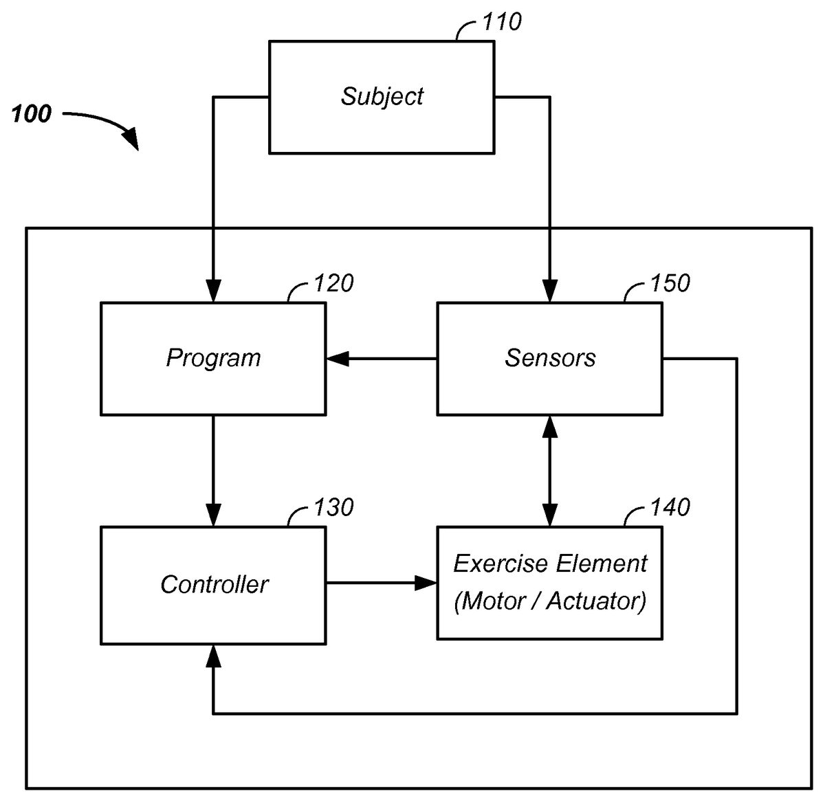
Referring now toFIG. 1, a block diagram of a motor equipped exercise system100is provided. As the exercise system100optionally provides resistance and/or assistance to a motion of user interface, such as a weightlifting bar or crank system, the motor equipped exercise system100is also referred to as a motor equipped resistance system, a resistance system, a motor equipped assistance system, and/or an assistance system. For clarity of presentation, examples provided herein refer to a resistance provided by a motor of the exercise system100. However, the motor of the exercise system100is alternatively configured to provide assistance. Hence, examples referring to motor supplied resistance are non-limiting and in many cases the system is alternatively reconfigured to use motor supplied assistance in the range of motion of a particular exercise.
In one example, the user interface is directly contacted and moved by the user. In a second example, the user interface does not contact the user; however, the user interface is indirectly moved by the user.
Still referring toFIG. 1, the exercise system100includes one or more of: a computer configured with a program120, a controller130, an exercise element140, and/or a sensor150. The exercise system100is optionally configured for use and/or configuration by a subject110or a remote trainer/physical therapist.
Still referring toFIG. 1, the subject110:enters a program120to the resistance system;alters the resistance of the exercise system100within a repetition;alters the resistance of the exercise system100between repetitions;is sensed by sensors150in the resistance system; and/oris recognized by the resistance system, such as through wireless means described infra.
The program120is optionally predetermined, has preset options, is configurable to a specific subject, changes resistance dynamically based on sensor input, and/or changes resistance based on subject input, described infra. The program120provides input to a controller130and/or a set of controllers, which controls one or more actuators and/or one or more motors of an exercise element140of the exercise system100. Optional sensors provide feedback information about the subject110and/or the state of a current exercise movement, such as a position, velocity, and/or acceleration of a moveable element of the resistance system, a force applied to a portion of the exercise system100, the subject's heart rate, and/or the subject's blood pressure. Signal from the sensors150are optionally fed in a feedback system or loop to the program120and/or directly to the controller130. For example, the heart rate of the user is measured using a heart rate monitor and the physical resistance supplied by the electric motor is varied to maintain the heart rate in a target zone.
Optionally, active computer control is coupled with motorized resistance in the exercise system100. The computer controlled motor allows for incorporation of progressive and reconfigurable procedures in strength training, physical conditioning, and/or cardiovascular exercise. For example, computer control of the motor additionally optionally provides resistance curves overcoming the traditional limits of gravity based freestyle weightlifting, described infra.
Linear Movement
Referring now toFIG. 2, a linear movement system200is illustrated, which is a species of the exercise system100. The linear movement system200is non-limiting, illustrative in nature, and is used for facilitating disclosure of the system. Further, the species of the linear movement system200is to a specific form of the exercise system100. However, the illustrated linear movement system200is only one of many possible forms of the exercise system100and is not limiting in scope. Herein the linear movement system refers to a linear, about linear, or non-rotational movement of the user interface exercise equipment, such as a weightlifting bar, or to movement of a resistance cable. Additionally, the linear movement system refers to a curved movement of the user interface, such as a path following physiological movement.
Still referring still toFIG. 2, an exemplary computer and motor aided linear movement system200is provided. Generally,FIG. 2illustrates examples of the structural elements140of the exercise system100. In the illustrated system, the linear movement system200includes:a base210, such as an aluminum extrusion or suitable materialan upright support member212affixed to the base;a removable weightlifting bar220placeable into a guide element of the upright support member212, or other geometry suitable for interfacing with the subject, such as a D-handle;a first end of a resistance cable230affixed to the weightlifting bar220;a cable spool242affixed to a second end of the resistance cable230;a resistance cable, such as flexible metallic cable, a fibrous cord, an about 0.053″ sheathed Kevlar cord, or an about 3/32″ T-100 cord, which is an example of a para-aramid synthetic fiber or an aramid synthetic fiber cord; and/oran electric motor240configured to provide resistance to movement of the weightlifting bar220through the resistance cable230.
As configured, the subject110stands on the floor, base210, a foot support or cross-member214of the base210, and/or an attachment thereto. The subject110pulls on the removable weightlifting bar220and/or on hand grips222affixed or attached to the weightlifting bar220. Movement of the weightlifting bar220is continuous in motion, but is illustrated at a first point in time, t1, and at a second point in time, t2, for clarity. The subject pulls the weightlifting bar220, such as along the z-axis. Movement of the weightlifting bar220is resisted by the electric motor240. For example, the electric motor240provides a resistive force to rotation of the cable spool242, which transfers the resistive force to the resistance cable230and to the weightlifting bar220pulled on by the subject110. In one example, the electric motor240includes no gearbox, a fixed 5:1 gear, a variable gearbox, or a low lash gearbox, and/or a MicroFlex drive to control motor torque. The torque produced by the motor is optionally made proportional to an analog voltage signal applied to one of the drive's analog inputs or is controlled by sending commands to set the torque value using a digital communications protocol.
Orientations
The linear movement system200is illustrated with the resistive cable230running in the z-axis. However, the resistive cable230optionally runs along the x-axis or any combination of the x-, y-, and z-axes. Similarly, the linear movement system200is illustrated for the user subject110standing on the floor. However, the exercise system100is optionally configured for use by the subject110in a sitting position or any user orientation. Further, the linear movement system200is illustrated with the subject110pulling up against a resistance. However, the subject is optionally pushing against a resistance, such as through use of a force direction changing pulley redirecting the resistance cable230. Still further, the linear movement system200is illustrated for use by the subject's hands. However, the system is optionally configured for an interface to any part of the subject, such as a foot or a torso.
Resistance/Assistance Profiles
Traditional weight training pulls a force against gravity, which is constant, and requires the inertia of the mass to be overcome. Particularly, a force, F, is related to the mass, m, moved and the acceleration, g, of gravity, and the acceleration of the mass, a, through equation 1,
F=mg+ma(eq. 1)
where the acceleration of gravity, g, is
9.81msec2.
Hence, the resistance to movement of the weight is non-linear as a function of time or as a function of movement of the user interactive element.
In one example, the physical resistance supplied by the electric motor is maintained at an iso-inertial resistance through the solving of the equation F=ma, such that the force is maintained at an about constant level despite the acceleration and/or deceleration of the user interface, where about constant is less than 1, 5, 10, or 20 percent of a maximum load within a repetition.
Referring now toFIG. 3, linear movement resistance profiles300are illustrated, where both the resistance and distance are in arbitrary units. For traditional free weight strength training, the external resistance profile is flat310as a function of distance. For example, on a bench press a loaded weight of 315 pounds is the resistance at the bottom of the movement and at the top of the movement where acceleration is zero. At positions in between the external force required to accelerate the mass is dependent on the acceleration and deceleration of the bar. In stark contrast, the exercise system100described herein allows for changes in the resistance as a function of position within a single repetition of movement. Returning to the bench press example, it is well known that the biomechanics of the bench press result in an ascending strength curve, such that one may exert greater force at the end of the range of motion than at the beginning. Hence, when the lifter successfully lifts, pushes, or benches through the “sticking point” of the bench press movement, the person has greater strength at the same time the least amount of force needs to exerted as the mass is deceleration resulting in the musculature of the chest being sub-optimally loaded. Accordingly, a variable resistance profile starting with a lower resistance and then increasing to a peak resistance is more optimal for a bench press.
Still referring toFIG. 3, still an additional profile is a profile where the force at the beginning of the lift (in a given direction) is about equal to the force at the end of the lift, such as a weight of mass times gravity. At points or time periods between the beginning of the lift and the end of the lift (in a given direction) the force applied by the electric motor optionally depends on whether the bar is accelerating or decelerating. For example, additional force is applied by the motor during acceleration and no additional force is applied by the motor during deceleration versus a starting weight. For example, the applied force profile is higher than a starting weight or initial force as the load is accelerated and less than or equal to the initial load as it movement of the repetition decelerates.
Still referring toFIG. 3, more generally the resistance profile300is optionally set:according to predetermined average physiological human parameters;to facilitate therapy of a weak point in a range of motion;to accommodate restricted range of motion, such as with a handicap;to rise and then fall within one-half of a single repetition, such as during movement in one direction;to fit a particular individual's physiology;to fit a particular individual's preference;in a pre-programmed fashion;by parameters coded in a video game;by parameters set by a trainer or medical professional;in a modified and/or configurable manner; and/ordynamically based onsensed values from the sensor150; and/orthrough real-time operator110input.
Several optional resistance profiles are illustrated, including: a step-down function resistance profile320, an increasing resistance profile330, and a peak resistance profile340. Physics based profiles include:accurate solution of F=mg+ma;accurate solution of
F=mg+{ma,(a>0)0,(a≤0)},which prevents the resistance from dropping below the baseline, static resistance; and/oraccurate solution of F=mg+maximum, which maintains the maximum resistance developed when accelerating the load through the remainder of the lift.
Additional profiles include a step-up profile, a decreasing resistance profile, a minimum resistance profile, a flat profile, a complex profile, and/or any permutation and/or combination of all or parts of the listed profiles. Examples of complex profiles include a first profile of sequentially increasing, decreasing, and increasing resistance or a second profile of decreasing, increasing, and decreasing resistance.
In one example, the resistance force to movement of the subject interface varies by at least 1, 5, 10, 15, 20, 25, 50, or 100 percent within a repetition or between repetitions in a single set. In another example, the resistance supplied by the electric motor varies by at least 1, 5, 10, 15, 20, 25, 50, or 100 percent in a period of less than 2, 3, 4, 5, 6, 7, 8, 9, or 10 seconds.
Reverse Movement
For the linear movement system200, resistance profiles were provided for a given direction of movement, such as an upward push on bench press. Through appropriate mounts, pulleys, and the like, the resistance profile of the return movement, such as the downward movement of negative of the bench press, is also set to any profile. The increased load is optionally set as a percentage of the initial, static load. For example, the downward force profile of the bench press are optionally set to match the upward resistance profile, to increase weight, such as with a an increased weight “negative” bench press, or to have a profile of any permutation and/or combination of all or parts of the listed profiles.
Time/Range of Motion
One or more sensors are optionally used to control rate of movement of the resistive cable. For example, the electric motor240is optionally configured with an encoder that allows for determination of how far the cable has moved. The encoder optionally provides input to the controller130which controls further movement of the actuator and/or motor turn, thereby controlling in a time controlled manner movement or position of the resistive cable.
In one example, the exercise system100senses acceleration and/or deceleration of movement of the movable exercise equipment, such as the weightlifting bar220. Acceleration and/or deceleration is measured using any of:an encoder associated with rotation of the electric motor;an accelerometer sensor configured to provide an acceleration signal; and/ora-priori knowledge of a range or motion of a given exercise type coupled with knowledge of:a start position of a repetition;a physical metric of the operator, such as arm length, leg length, chest size, and/or height.
Since putting an object into motion takes an effort beyond the force needed to continue the motion, such as through a raising period of a bench press, the forces applied by the motor are optionally used to increase or decrease the applied force based on position of movement of the repetition. The encoder, a-priori knowledge, physical metrics, and/or direct measurement with a load cell, force transducer, or strain gage are optionally used in formulation of the appropriate resistance force applied by the electric motor240as a function of time.
Exercise Types
Thus far, concentric and eccentric exercises configurable with the exercise system100have been described. Optionally, isometric exercises are configurable with the exercise system100. An isometric exercise is a type of strength training where a joint angle and a muscle length do not vary during contraction. Hence, isometric exercises are performed in static positions, rather than being dynamic through a range of motion. Resistance by the electric motor240transferred through the resistive cable230to the weightlifting bar220allows for isometric exercise, such as with a lock on the motor or cable, and/or through use of a sensor, such as the encoder. An additional example is an interface for grip strength operating against the motor.
Rotational Movement
Thus far, the linear movement system200species of the exercise system100has been described. Generally, elements of the linear movement system200apply to a rotational movement system400species of the exercise system100genus. In a rotary movement system, the electric motor240provides resistance to rotational force.
Referring now toFIG. 4, a rotational movement system400is illustrated, which is a species of the exercise system100. The rotational movement system400is non-limiting, illustrative in nature, and is used for facilitating disclosure of the system. Further, the species of the rotational movement system400is to a specific form of the exercise system100, for clarity of presentation. However, the illustrated rotational movement system400is only one of many possible forms of the exercise system100and is not limiting in scope.
Still referring still toFIG. 4, an exemplary computer and motor aided rotational movement system400is provided. Generally,FIG. 4illustrates examples of the structural elements140of the exercise system100. In the illustrated system, the rotational movement system400includes:a support base410;an upright support member422affixed to the base;an operator support420, such as a seat, affixed to the upright support member422;a hand support430affixed to the upright support member422;a crank assembly440supported directly and/or indirectly by the support base410or a support member;pedals450attached to the crank assembly440;an electric motor240;a rotational cable442affixed to the crank assembly440and to the motor240;control electronics246electrically connected to at least one of the electric motor240and controller130;a display screen494attached to a display support492, which is directly and or indirectly attached to the support base410; and/oran aesthetic housing480, which is optionally attached, hinged, or detachable from the support base410.
In stark contrast with a power generation system where a user pedals a crank and generates power, the system herein described optionally uses an electric motor to provide a resistance against which the person exercising needs to exert force.
Orientations
As with the with linear movement system200, the orientations of the rotational movement system400are optionally configurable in any orientation and/or with alternative body parts, such as with the hands and arms instead of with feet and legs.
Resistance/Assistance Profiles
As described, supra, with respect to the linear movement system200, traditional rotary systems have a preset resistance, which is either flat or based upon a fixed cam or set of fixed cams. Referring now toFIG. 5, rotational movement resistance profiles500are illustrated, where the resistance is in arbitrary units as a function of rotation angle theta. For traditional rotation systems, the resistance profile is flat510as a function of rotation. In stark contrast, the exercise system100described herein allows for changes in the resistance as a function of rotation within a single revolution of movement and/or with successive revolutions of the rotating element. Typically, resistance variation is a result of changes in the electric motor supplied resistance.
An example of rotation of a bicycle crank illustrates differences between traditional systems and resistance profiles available using the rotational movement system500. A flat resistance profile versus rotation510is typical. However, the physiology of the body allows for maximum exerted forces with the right leg at about 45 degrees of rotation of the crank (zero degrees being the 12 o'clock position with a vertical rotor) and maximum exerted forces by the left leg at about 225 degrees of rotation of the crank. The computer controlled electric motor240allows variation of the resistance profile as a function of rotational angle520. Unlike a cam system or a bicycle equipped with an elliptical crank, the resistance profile is alterable between successive revolutions of the crank via software and/or without a mechanical change.
Still referring toFIG. 5, more generally the resistance profile500of the rotational exercise system400is optionally set:according to predetermined average physiological human parameters;to facilitate therapy of a weak point in a range of motion;to accommodate restricted range of motion, such as with a handicap;to fit a particular individual's physiology;to fit a particular individual's preference;in a pre-programmed fashion;according to a video game program;according to an exercise program on a display screen;in a modified and/or configurable manner; and/ordynamically based onsensed values from the sensor150; and/orthrough real-time operator110input.
Several optional rotational resistance profiles are possible, including: a step function resistance profile, a changing resistance profile within a rotation and/or between rotations, a range or programs of resistance profiles. Additional profiles include any permutation and/or combination of all or parts of the profiles listed herein for the linear movement system200and/or the rotational movement system400.
Combinatorial Linear and Rotation Systems
Referring now toFIG. 6, a combinatorial movement system200is illustrated. In the illustrated example, a single electric motor240is used for control of two or more pieces of exercise equipment, such as:an isometric station;a linear movement system200;a curved movement system; anda rotational movement system400.
Generally, the single electric motor240optionally provides resistance to 1, 2, 3, 4, 5, or more workout stations of any type.
Still referring toFIG. 6, an exercise system is figuratively illustrated showing interfaces for each of: (1) a linear movement system200and (2) a rotational movement system200with a motor240and/or motor controlled wheel462. The combinatorial movement system600is illustrative in nature and is used for facilitating disclosure of the system. However, the illustrated combinatorial movement system600is only one of many possible forms of the exercise system100and is not limiting in scope.
Sensors
Optionally, various sensors150are integrated into and/or are used in conjunction with the exercise system100.
Operator Input
A first type of sensor includes input sources to the computer from the operator110. For example, the hand support430of the rotational movement system400is optionally configured with one or more hand control432buttons, switches, or control elements allowing the operator110to adjust resistance and/or speed of the electric motor240within a repetition and/or between repetitions. For example, an increase weight button is optionally repeatedly depressed during raising of a weight, which incrementally increases the load applied by the electric motor240. A similar button is optionally used to decrease the weight. Similarly foot control buttons452are optionally used to achieve the same tasks, such as when the hands are tightly gripped on a weightlifting bar.
Instrumentation Sensor
A second type of sensor150delivers information to the computer of the exercise system100. In a first example, the pedals450of the bicycle assembly are optionally equipped with sensors150as a means for measuring the force applied by a operator110to the pedals. As a second example, the linear motion system200and/or rotational motion system400optionally contains sensors150for measuring load, position, velocity, and/or acceleration of any movable element, such as the pedals450or the weightlifting bar200.
For example, muscle loading is controlled using the resistance force exerted on the bar by the electric motor. Position, velocity, and acceleration data are provided by an encoder on the motor and are used as feedback in the control system. For additional muscular overload, often more weight is lowered than can be raised. The lowering or eccentric phase of the exercise can be controlled in real-time for eccentric overload. Muscle loading control and data acquisition is optionally performed, for example, in a dataflow programming language where execution is determined by the structure of a graphical block diagram which the programmer connects different function-nodes by drawing wires, such as LabView® or other suitable software.
Radio-Frequency Identification
A third type of sensor150delivers information to the computer of the exercise system100from the operator. For example, the operator wears a radio-frequency identification (RFID) tag, such as in a belt, shoe, wallet, cell phone, article of clothing, or an embedded device. The radio frequency identification identifies the operator to the exercise system100along with information, such as any of:an operator name;an operator gender;an operator age;an operator height;an operator weight;an operator physical characteristic, such as arm length, leg length, chest size for an exercise like a bench press;an operator workout preference;an operator workout history; andan operator goal.
The radio-frequency identification tag is of any type, such as active or battery powered, passive, and battery assisted passive. Generally, wireless signal is received by the exercise equipment100from a broadcast source, such as from a global positioning system or RFID tag.
Computer
The motor drive controller130is optionally connected to a microprocessor or computer and power electronics that are used to control the electric motor240. The power electronics are connected to a power supply such as a battery or power outlet. The computer, the electric drive unit, and the sensors150optionally communicate with one another to form feedback control loops allowing the profile of the force and/or resistance applied to the operator110. The computer optionally provides: a user interface, data storage and processing, and/or communication with other computers and/or a network.
A visual feedback system or display screen494is also optionally used to provide the user with immediate feedback on velocity tracking ability and/or other exercise related parameters. Velocity tracking is particularly useful for systems designed for patients in rehabilitation settings.
Gaming System
In yet another embodiment, the exercise system100is used in conjunction with a gaming system700, such as a video game system where the exercise system provides real physical resistance to an interface, the results of which are integrated into a video game, such as running on a game console.
Referring now toFIG. 7, an example of the exercise system100used in combination with a gaming system700is illustrated. This example is used for clarity of presentation and is not limiting in scope. In this example, the user110uses the exercise system100, which is in communication with the gaming system700. The gaming system700optionally includes:a game console710;a display device720, such as a display screen494;a communication element730;a sensing element740; and/ora user controller.
Game Console
A game console710is an interactive entertainment computer or customized computer system that produces a video display signal that is optionally used with a display device, described infra. Herein, a game console includes a video game system and/or a computer system. The game console710is optionally embedded with and/or in the exercise system100. Examples of game consoles710include: a computer in the exercise system100or any form of proprietary or commercially available gaming system, such as those produced by Nintendo® (Kobe, Japan), Sony® (Tokyo, Japan), Microsoft® (Redmond, Wash.), or the like. Particular examples of video game consoles include the Wii® (Nintendo, Kobe, Japan), PlayStation® (Sony, Tokyo, Japan), Xbox®, (Microsoft, Redmond, Wash.), or the like.
Display Device
A display device720outputs a video display signal, such as from an external game console710or from an internal computer of the exercise system100. Examples of a display device720include: a television, a monitor, an optically emitting diode display, or a personal display device, such as a smart phone or tablet. The display device720is optionally used to display output of: a video game, an exercise program, a physical therapy routine, and/or a medical program.
Communication Element
A communication element740includes any element used to convey any form of information from the exercise system100to the gaming system700or vise-versa. Examples of a communication element740include a wired and/or wireless digital link726between the exercise system100and game system700carrying analog and/or digital information; a signal transmitted from the gaming system wirelessly742using any part of the electromagnetic spectrum; an optical signal; and a signal transmitted from the exercise system wirelessly744using any part of the electromagnetic spectrum. For example, any signal generated via the interaction of the user110with the exercise system100is optionally transmitted to the gaming system700. Examples of transmitted signals include output of any of: a sensor; an accelerometer; a user input; or a spatial location system, such as via the use of a controller described infra. Similarly, examples of transmitted signals include any output from the gaming system700received by the exercise system100. Still further, examples of “transmitted” signals include any information received from the user, such as position, and/or received by the gaming system, such as through a sensing element730described infra.
Sensing Element
The sensing element730includes any system, sensor, and/or element used to receive and/or derive information about the environment and/or the user110. For example, the sensing element730receives 3-D information from a controller, motion information from an accelerometer, physiology information from a user sensor, and/or environment information, such as through infrared detection, use of any portion of the electromagnetic spectrum, and/or via a temperature, pressure, work, or force sensor. Examples of sensing elements730include induced signals, such as reflectance of an ultraviolet, visible, and/or infrared source; a one, two, or three dimensional accelerometer; a light sensor or light gun sensor; a yaw, tilt, or roll sensor; a rotation sensor; a sensor bar; a sensor array; and/or combinatorial use of multiple sensor types. Preferably, the sensing element730is configured with an analyzer to interpret the received signals and a link to the gaming system700or game console710.
User Controller
The user controller senses actions of the user110. The user controller uses input from the user110and/or from the controller130. The user controller directly and/or indirectly sends collected data and/or information to the gaming system700.
Games
Generally, a video game is any electronic game that involves human interaction with a user interface to generate visual feedback on a video device. Hence, any list of video games is necessarily non-inclusive. However, some video games lend themselves to interaction and use of the exercise system100, such as games involving:a pumping action, such as filling an animated liquid or gas container;a lifting action, such as a bench press, overhead press, or squat; and/ora pedaling action.
An additional video game example is use of the exercise system in a strongman competition video game. Generally, any movement of an element of the exercise system100is optionally visualized and/or integrated into the game system700.
Online/Internet/Cloud
Any of the exercise system100inputs and/or outputs are optionally shared online, over a local area network, over the internet and/or are made part of the cloud. Any of the shared information is optionally used with interaction of a physical therapist, medical professional, doctor, and/or in an online competition.
Microgravity
In yet another embodiment, the exercise system100described herein is designed for use in a microgravity environment. Variations include use of lightweight materials, straps for holding an astronaut relative to the exercise system, and an emphasis on foldable and/or collapsible parts. In one case, equally applicable to full gravity environments, energy generated through use of the exercise system is captured and stored in a battery.
Compact/Reconfigurable System
As described in U.S. patent application Ser. No. 12/545,324, which is incorporated herein, the system100is optionally configured as a compact strength training system that provides the benefits associated with free weight lifting and/or aerobic training. Optionally, structure of the exercise system100is optionally manually or robotically reconfigurable into different positions, such as a folded position for storage. For example, the weightlifting bar220folds, the operator support420folds, and/or the support base410folds or telescopes.
Still yet another embodiment includes any combination and/or permutation of any of the elements described herein.
The particular implementations shown and described are illustrative of the invention and its best mode and are not intended to otherwise limit the scope of the present invention in any way. Indeed, for the sake of brevity, conventional manufacturing, connection, preparation, and other functional aspects of the system may not be described in detail. Furthermore, the connecting lines shown in the various figures are intended to represent exemplary functional relationships and/or physical couplings between the various elements. Many alternative or additional functional relationships or physical connections may be present in a practical system.
In the foregoing description, the invention has been described with reference to specific exemplary embodiments; however, it will be appreciated that various modifications and changes may be made without departing from the scope of the present invention as set forth herein. The description and figures are to be regarded in an illustrative manner, rather than a restrictive one and all such modifications are intended to be included within the scope of the present invention. Accordingly, the scope of the invention should be determined by the generic embodiments described herein and their legal equivalents rather than by merely the specific examples described above. For example, the steps recited in any method or process embodiment may be executed in any order and are not limited to the explicit order presented in the specific examples. Additionally, the components and/or elements recited in any apparatus embodiment may be assembled or otherwise operationally configured in a variety of permutations to produce substantially the same result as the present invention and are accordingly not limited to the specific configuration recited in the specific examples.
Benefits, other advantages and solutions to problems have been described above with regard to particular embodiments; however, any benefit, advantage, solution to problems or any element that may cause any particular benefit, advantage or solution to occur or to become more pronounced are not to be construed as critical, required or essential features or components.
As used herein, the terms “comprises”, “comprising”, or any variation thereof, are intended to reference a non-exclusive inclusion, such that a process, method, article, composition or apparatus that comprises a list of elements does not include only those elements recited, but may also include other elements not expressly listed or inherent to such process, method, article, composition or apparatus. Other combinations and/or modifications of the above-described structures, arrangements, applications, proportions, elements, materials or components used in the practice of the present invention, in addition to those not specifically recited, may be varied or otherwise particularly adapted to specific environments, manufacturing specifications, design parameters or other operating requirements without departing from the general principles of the same.
Although the invention has been described herein with reference to certain preferred embodiments, one skilled in the art will readily appreciate that other applications may be substituted for those set forth herein without departing from the spirit and scope of the present invention. Accordingly, the invention should only be limited by the Claims included below.
Claims
- A method for a user exercising using an exercise system coupled with a video game system, comprising the steps of: providing an exercise system, said exercise system comprising: a user interface;a cable;and an electric motor, wherein said electric motor provides physical resistance to movement of said user interface through said cable;altering a resistance profile provided to said cable from said electric motor between successive repetitions of movement of said user interface via software and without a mechanical change;and means for communication between said exercise system and the external video game system, wherein the user operates said user interface against resistance provided by said electric motor.
- The method of claim 1 , further comprising the step of: said exercise system providing isometric resistance to an applied force of the user.
- The method of claim 1 , further comprising the steps of: running said cable through a force direction changing pulley;and the user pushing against resultant resistance provided by said electric motor.
- The method of claim 1 , further comprising the step of: increasing the physical resistance to the user interface by at least ten percent during one-half of a repetition of a weightlifting exercise.
- The method of claim 1 , further comprising the step of: first increasing the physical resistance supplied by said electric motor during one-half of repetition of an exercise repetition;and subsequently decreasing the physical resistance supplied by said electric motor during said one-half of said repetition of said exercise repetition.
- The method of claim 1 , further comprising the steps of increasing said resistance supplied by said electric motor when said user interface is accelerating.
- The method of claim 6 , further comprising the step of: providing a sensor linked to said controller;and using output of said sensor to determine when said user interface is accelerating.
- The method of claim 1 , further comprising the step of: at least one of: (1) a trainer and (2) a therapist remotely changing said physical resistance supplied by the electric motor to said user.
- The method of claim 1 , further comprising the step of: capturing and storing energy generated by use of said exercise system into a battery.
- The method of claim 1 , further comprising the steps of: monitoring a heart rate of the user using output of a heart rate monitor;and varying the physical resistance supplied by said electric motor to maintain the heart rate in a target zone.
- A method for a user exercising using an exercise system coupled with a video game system, comprising the steps of: providing an exercise system, said exercise system comprising: a user interface;a cable;and an electric motor, wherein said electric motor provides physical resistance to movement of said user interface through said cable;and means for communication between said exercise system and the external video game system, wherein the user operates said user interface against resistance provided by said electric motor;and using said electric motor for successive control of two or more exercise stations.
- A method for a user exercising using an exercise system coupled with a video game system, comprising the steps of: providing an exercise system, said exercise system comprising: a user interface;a cable;and an electric motor, wherein said electric motor provides physical resistance to movement of said user interface through said cable;and means for communication between said exercise system and the external video game system, wherein the user operates said user interface against resistance provided by said electric motor, wherein said physical resistance comprises a dynamic computer controlled iso-inertial resistance, varying based on acceleration of said user interface element.
Disclaimer: Data collected from the USPTO and may be malformed, incomplete, and/or otherwise inaccurate.