U.S. Pat. No. 9,120,012
GAME SYSTEM, NON-TRANSITORY COMPUTER-READABLE STORAGE MEDIUM HAVING GAME PROGRAM STORED THEREON, GAME PROCESSING METHOD, AND GAME APPARATUS, FOR PERFORMING GAME PROCESSING BASED ON POINTED POSITIONS ON MULTIPLE, DIFFERENTLY ORIENTED, DISPLAY DEVICES
AssigneeNINTENDO CO., LTD.
Issue DateJune 18, 2013
Illustrative Figure
Abstract
A first display device is placed so that its screen faces in a direction along a gravity direction axis, and a second display device is placed so that its screen faces in a predetermined axis direction perpendicular to the gravity direction axis. Based on data of a motion sensor which is outputted from an operation device including the motion sensor, an attitude of the operation device is calculated, and it is determined which of the first display device and the second display device the operation device faces. Then, based on the result of the determination, a predetermined position on either the screen of the first display device or the screen of the second display device is pointed to, and a predetermined game process is performed based on the pointed position.
Description
DETAILED DESCRIPTION OF NON-LIMITING EXAMPLE EMBODIMENTS Hereinafter, an exemplary embodiment will be described. Hereinafter, a game system1according to the exemplary embodiment will be described with reference to the drawings.FIG. 1is an external view of the game system1. InFIG. 1, the game system1includes: a stationary display device (hereinafter, referred to as “television”)2typified by, for example, a television receiver; a stationary game apparatus3; controllers5; a terminal apparatus7; and a marker device8. The game system1performs game processing in the game apparatus3on the basis of a game operation with each controller5, and displays a game image obtained by the game processing, on the television2and/or the terminal apparatus7. An optical disc (not shown) which is an example of an information storage medium exchangeably used to the game apparatus3, is detachably inserted into the game apparatus3. The television2is connected to the game apparatus3via a connection cord. The television2displays the game image obtained by the game processing performed in the game apparatus3. It is noted that in another embodiment, the game apparatus3and the stationary display device may be integrated with each other. In addition, communication between the game apparatus3and the television2may be wireless communication. In the periphery of the screen of the television2(above the screen inFIG. 1), the marker device8is installed. Although described in detail later, a user (player) can perform a game operation of moving the controller5. The marker device8is used by the game apparatus3to calculate the motion, position, attitude and the like of the controller5. The marker device8includes two markers8R and8L at its two ends. Specifically, the marker8R (the same applies to the marker8L) is composed of one or more infrared LEDs (Light Emitting Diodes), and outputs infrared light forward from the television2. The marker device8is connected to the game apparatus3, and the game apparatus3can control each of the infrared LEDs included in the marker ...
DETAILED DESCRIPTION OF NON-LIMITING EXAMPLE EMBODIMENTS
Hereinafter, an exemplary embodiment will be described.
Hereinafter, a game system1according to the exemplary embodiment will be described with reference to the drawings.FIG. 1is an external view of the game system1. InFIG. 1, the game system1includes: a stationary display device (hereinafter, referred to as “television”)2typified by, for example, a television receiver; a stationary game apparatus3; controllers5; a terminal apparatus7; and a marker device8. The game system1performs game processing in the game apparatus3on the basis of a game operation with each controller5, and displays a game image obtained by the game processing, on the television2and/or the terminal apparatus7.
An optical disc (not shown) which is an example of an information storage medium exchangeably used to the game apparatus3, is detachably inserted into the game apparatus3.
The television2is connected to the game apparatus3via a connection cord. The television2displays the game image obtained by the game processing performed in the game apparatus3. It is noted that in another embodiment, the game apparatus3and the stationary display device may be integrated with each other. In addition, communication between the game apparatus3and the television2may be wireless communication.
In the periphery of the screen of the television2(above the screen inFIG. 1), the marker device8is installed. Although described in detail later, a user (player) can perform a game operation of moving the controller5. The marker device8is used by the game apparatus3to calculate the motion, position, attitude and the like of the controller5. The marker device8includes two markers8R and8L at its two ends. Specifically, the marker8R (the same applies to the marker8L) is composed of one or more infrared LEDs (Light Emitting Diodes), and outputs infrared light forward from the television2. The marker device8is connected to the game apparatus3, and the game apparatus3can control each of the infrared LEDs included in the marker device8to be lit on or off.
Each controller5provides the game apparatus3with operation data representing the content of an operation performed on the controller5itself. Each controller5and the game apparatus3are able to communicate with each other by means of wireless communication. In the exemplary embodiment, each controller5and the game apparatus3wirelessly communicate with each other using, for example, the Bluetooth (registered trademark) technology. It is noted that in another embodiment each controller5and the game apparatus3may be connected to each other in a wired manner. The game apparatus3is able to communicate with a plurality of controllers, and a plurality of players are allowed to play a game by simultaneously using a predetermined number of controllers. In the exemplary embodiment, it is assumed that the number of the controllers5included in the game system1is two so that two players are allowed to play a game simultaneously. The detailed configuration of each controller5will be described later.
The terminal apparatus7has a size small enough to be held by the user, and the user is allowed to move the terminal apparatus7with hands or place the terminal apparatus7at any location when using the terminal apparatus7. Although the detailed configuration of the terminal apparatus7will be described later, the terminal apparatus7includes an LCD (Liquid Crystal Display)71as display means, and input means (such as a touch panel72and a motion sensor82described later). The terminal apparatus7and the game apparatus3are able to communicate with each other wirelessly (or via wired means). The terminal apparatus7receives, from the game apparatus3, data of an image (e.g., a game image) generated in the game apparatus3, and displays the image on the LCD71. In addition, the terminal apparatus7transmits, to the game apparatus3, operation data representing the content of an operation performed on the terminal apparatus7.
FIG. 2is a block diagram of the game apparatus3that is an example of an information processing apparatus. InFIG. 2, the game apparatus3includes a CPU (control section)11, a memory12, a system LSI13, a controller communication section14, a codec LSI15, a terminal apparatus communication section16, an AV-IC (Audio Video-Integrated Circuit)20, and the like.
The CPU11performs a predetermined information processing program (the game program in the exemplary embodiment) by using the memory12, the system LSI13, and the like. By so doing, various functions (e.g., the game processing) in the game apparatus3are realized. The CPU11is connected to the system LSI13.
The system LSI13includes a PGU (Graphics Processor Unit)17, a DSP (Digital Signal Processor)18, an input-output processor19, and the like. The GPU17generates an image in accordance with a graphics command (image generation command) from the CPU11. It is noted that in the present embodiment, the game apparatus3generates both a game image to be displayed on the television2and a game image to be displayed on the terminal apparatus7. Hereinafter, the game image to be displayed on the monitor2may be referred to as “television game image”, and the game image to be displayed on the terminal apparatus7may be referred to as “terminal game image”.
The DSP18functions as an audio processor and generates audio data using sound data and acoustic waveform (tone quality) data that are stored in the memory12.
The input-output processor19transmits/receives data to/from components connected thereto, and downloads data from an external apparatus. The input-output processor19is connected to the controller communication section14, the codec LSI15, and the AV-IC20. An antenna (not shown) is connected to the controller communication section14. The codec LSI15is connected to the terminal apparatus communication section16, and an antenna (not shown) is connected to the terminal apparatus communication section16. The input-output processor19transmits/receives data to/from each controller5via the controller communication section14. For example, the input-output processor19receives operation data transmitted from each controller5and stores (temporarily stores) the operation data into a buffer area of the memory12.
Data of an image and a sound to be outputted in the television2, among images and sounds generated in the game apparatus3, is read by the AV-IC20. The AV-IC20outputs the read image data to the television2via an AV connector (not shown), and outputs the read audio data via the AV connector to the speakers2L and2R included in the television2. By so doing, the image is displayed on the television2, and the sound is outputted from the speakers2L and2R.
The game apparatus3is able to transmit/receive data of images, sounds, and the like to/from the terminal apparatus7. When transmitting a game image (terminal game image) to the terminal apparatus7, the input-output processor19outputs data of a game image generated by the GPU17, to the codec LSI15. The codec LSI15performs a predetermined compression process on the image data outputted from the input-output processor19. The terminal apparatus communication section16performs wireless communication with the terminal apparatus7. Accordingly, the image data compressed by the codec LSI15is transmitted by the terminal apparatus communication section16to the terminal apparatus7. In addition to the image data, the game apparatus3transmits audio data to the terminal apparatus7. Specifically, the input-output processor19outputs audio data generated by the DSP18, to the terminal apparatus communication section16via the codec LSI15. Similarly to the image data, the codec LSI15also performs a compression process on the audio data. The terminal apparatus communication section16transmits the compressed image data and the compressed audio data to the terminal apparatus7.
In addition, the game apparatus3transmits, as well as the image data and the audio data described above, various control data to the terminal apparatus7where necessary. The control data is data representing a control instruction to be given to a component included in the terminal apparatus7. The control data represents, for example, an instruction to control a marker section (marker sections78L and78R shown inFIG. 5described later). The input/output processor19transmits the control data to the terminal apparatus7in accordance with an instruction from the CPU11.
In addition, the game apparatus3is able to receive various data from the terminal apparatus7. For example, the terminal apparatus7transmits operation data. The input-output processor19stores (temporarily stores) the data received from the terminal apparatus7, into the buffer area of the memory12.
Next, the controller5will be described.FIG. 3is a perspective view showing the external configuration of each controller5. InFIG. 3, the controller5includes a housing51that is formed by, for example, plastic molding. In addition, the controller5includes a cross key52, a plurality of operation buttons53, and the like as an operation section (an operation section61shown inFIG. 4). The controller5further includes a motion sensor. The player is allowed to perform a game operation by pressing each button provided in the controller5, and by moving the controller5itself to change its position and attitude.
Further, the controller5includes an imaging information calculation section65(FIG. 4). A light incident surface of the imaging information calculation section65is provided on the front surface of the housing51. The light incident surface is formed of a material that allows at least infrared light from the markers8R and8L to pass therethrough.
FIG. 4is a block diagram showing the configuration of each controller5. The controller5includes the operation section61(the operation buttons52to53), a control section62, a motion sensor63, a wireless communication section64, and the imaging information calculation section65. The controller5transmits data representing the content of an operation performed on the controller5, as operation data to the game apparatus3.
The control section62controls an operation in the controller5. Specifically, the control section62receives the data outputted from the respective input sections (the operation section61, the motion sensor63, and the imaging information calculation section65), and transmits the data as operation data to the game apparatus3via the wireless communication section64.
The motion sensor63is a sensor for detecting the attitude of the controller5. In the exemplary embodiment, an acceleration sensor is provided as an example of the motion sensor63. The acceleration sensor can detect accelerations in three-axis (x-axis, y-axis, and z-axis) directions. More specifically, the acceleration sensor detects linear accelerations in three axial directions, i.e., the up-down direction (the y-axis direction shown inFIG. 3), a left-right direction (the x-axis direction shown inFIG. 3), and a front-rear direction (the z-axis direction shown inFIG. 3) based on the controller5. Since the acceleration sensor37detects the acceleration in the linear direction along each axis, the output from the acceleration sensor37represents the values of the linear accelerations in the three axes. That is, the detected accelerations are represented as a three-dimensional vector in an xyz coordinate system (a controller coordinate system) set on the basis of the controller5. It is noted that the acceleration detected by the acceleration sensor varies depending on the direction (the angle of tilt) or the movement of the controller5, and therefore, the game apparatus3can calculate the direction and the movement of the controller5by using the obtained acceleration data. In the exemplary embodiment, the game apparatus3calculates the attitude, the angle of tilt, and the like of the controller5, based on the obtained acceleration data.
Further, the controller5includes the wireless communication section64which can wirelessly communicate with the game apparatus3. In the exemplary embodiment, the controller5and the game apparatus3wirelessly communicate with each other. However, in another embodiment, the controller5and the game apparatus3may communicate with each other via wired means.
Further, the controller5includes the imaging information calculation section65. The imaging information calculation section65is a system for analyzing image data taken by imaging means and calculating the position of the center of gravity, the size, and the like of an area having a high brightness in the image data. The imaging information calculation section65has, for example, a maximum sampling period of about 200 frames/sec., and therefore, can trace and analyze even a relatively fast motion of the controller5.
The imaging information calculation section65includes an infrared filter65a, a lens65b, an image pickup element65c, and an image processing circuit65d. The infrared filter65aallows, among light incident on the front surface of the controller5, only infrared light to pass therethrough. The lens65bcollects the infrared light having passed through the infrared filter65a, and emits the infrared light to the image pickup element65c. The image pickup element65cis a solid-state image pickup device such as a CMOS sensor or a CCD sensor. The image pickup element65creceives the infrared light collected by the lens65b, and outputs an image signal. Here, the capturing targets, i.e., the marker device8and a marker section78of the terminal apparatus7described later, each include markers that output infrared light. Therefore, the provision of the infrared filter65aallows the image pickup element65cto receive only the infrared light having passed through the infrared filter65a, and generate image data. This makes it possible to accurately capture the capturing targets (the marker section78and/or the marker device8). Hereinafter, an image captured by the image pickup element65cis referred to as a “captured image”. The image data generated by the image pickup element65cis processed by the image processing circuit65d. The image processing circuit65dcalculates the positions of the capturing targets in the captured image. The image processing circuit65doutputs coordinates representing the calculated positions to the control section62. Data of the coordinates is transmitted from the control section62to the game apparatus3as operation data. Hereinafter, the coordinates described above are referred to as “marker coordinates”. The marker coordinates change in accordance with the direction (the angle of tilt) and the position of the controller5, and therefore, the game apparatus3can calculate the direction and the position of the controller5by using the marker coordinates.
The controller5also includes a loudspeaker (not shown) as sound output means.
Next, the configuration of the terminal apparatus7will be described with reference toFIG. 5.FIG. 5is a diagram showing the external configuration of the terminal apparatus7. InFIG. 5, (a) is a front view of the terminal apparatus7; (b) is a top view of the terminal apparatus7; (c) is a right side view of the terminal apparatus7; and (d) is a bottom view of the terminal apparatus7.
As shown inFIG. 5, the terminal apparatus7includes a housing70that generally has a plate-like horizontally-long rectangular shape. The housing70has a size small enough to be held by the user. Therefore, the user is allowed to move the terminal apparatus7with hands or change the location of the terminal apparatus7.
The terminal apparatus7includes the LCD71on a front surface of the housing70. The LCD71is provided near the center of the front surface of the housing70. In addition, the terminal apparatus7includes, as one of operations means, a touch panel72on the screen of the LCD71. Further, the terminal apparatus7includes, as operation means, two analog sticks75L and75R, a cross button76, and a plurality of buttons77(corresponding to an operation section81shown inFIG. 6). Each of the analog sticks75L and75R is a device for designating a direction.
Further, the terminal apparatus7includes loudspeakers as sound output means. As shown inFIG. 5(d), speaker holes79are provided in the lower side surface of the housing70. A sound is output through the speaker holes79from the loudspeakers. In the exemplary embodiment, the terminal apparatus7has two loudspeakers, and the speaker holes79are provided at positions corresponding to a left loudspeaker and a right loudspeaker.
As shown inFIG. 5(a), the terminal apparatus7includes a marker section78including markers78L and78R on the front surface of the housing70. The marker section78is provided above the LCD71. Similarly to the markers8L and8R of the marker device8, the markers78L and78R are each composed of one or more infrared LEDs. Similarly to the marker device8described above, the marker section78is used to cause the game apparatus3to calculate the motion of the controller5, and the like. The game apparatus3is capable of controlling the infrared LEDs of the marker section78to be lit on or off.
Next, the internal configuration of the terminal apparatus7will be described with reference toFIG. 6.FIG. 6is a block diagram showing the internal configuration of the terminal apparatus7. As shown inFIG. 6, in addition to the components shown inFIG. 5, the terminal apparatus7includes a control section83, a wireless communication section84, a motion sensor82, and the like. These electronic components are mounted on an electronic circuit substrate and accommodated in the housing70.
The motion sensor82is a sensor for detecting the attitude of the terminal apparatus7. In the exemplary embodiment, an acceleration sensor, an angular velocity sensor, and a magnetic sensor, as examples of the motion sensor82.
The control section83includes an UI controller85, a codec section86, and the like. The UI controller85controls input/output of data to/from the respective input/output sections. The codec section86performs a compression process on data to be transmitted to the game apparatus3, and a decompression process on data transmitted from the game apparatus3. The control section83transmits the operation data obtained from the touch panel72, the operation section81(the analog sticks75L and75R, the cross button76, and the plurality of buttons77), and the motion sensor82, to the game apparatus3via the wireless communication section84, as terminal operation data. As described above, the compressed image data and sound data are transmitted from the game apparatus3to the terminal apparatus7. These data are transmitted to the control section83via the wireless communication section84. The (codec section86of) control section83decompresses the received image data and sound data. The decompressed image data is output to the LCD71, and an image is displayed on the LCD71(a terminal game image is displayed). Meanwhile, the decompressed sound data is output to a sound IC (not shown), and the sound IC causes loudspeakers (not shown) to output a sound (a terminal game sound is output).
Next, an outline of game processing performed in the game system1according to the exemplary embodiment will be described with reference toFIGS. 7 to 15. The game system1enables an operation (pointing operation) of pointing to a position on a screen of each of two display devices, i.e., the television2and the terminal apparatus7, by using the controller5.
In the game processing assumed in the exemplary embodiment, a plurality of players are allowed to play a game. In the following description, a case where two players play a game will be described. In this game, each player holds a controller5, points to the screen of the television2or the screen of the terminal apparatus7with the controller5, and performs a predetermined operation (in other words, each player performs an operation such as capturing the marker device8or the marker section78with the controller5). Thus, the game is progressed.
Specific examples of screens and player's operations in the game assumed in the exemplary embodiment will be described. First, in the exemplary embodiment, the terminal apparatus7is placed so as to be parallel to the floor as shown inFIG. 7.FIG. 7is a schematic diagram showing the state immediately after the game has started. At this time, the terminal apparatus7is placed so that the LCD71of the terminal apparatus7faces upward. In other words, the terminal apparatus7is placed so that the LCD71faces in a direction along a gravity direction axis. In contract, the television is placed so that the screen of the television2faces in a direction along an axis perpendicular to the gravity direction axis. In the example ofFIG. 7, the LCD71faces in the positive direction of the y axis that is the gravity direction axis, and the screen of the television2faces in the negative direction of the z axis.
The terminal apparatus7is preferably placed at some distance from the television2. For example, the terminal apparatus7is placed at a position1to 2 m distant from the television2.
On the premise of the positional relation between the terminal apparatus7and the television2, the following game processing is performed in the exemplary embodiment. The exemplary game is a game of a water scooping race. In this game, each controller5is likened to a “ladle”, the terminal apparatus7is likened to a “stream”, and the television2is likened to a “container for water”. Each player performs an operation of scooping “water” from the terminal apparatus7as a “stream” by using the controller5as a “ladle”. Then, the player performs an operation of conveying the “water” to the television2as the “container for water”, and pouring the “water” into the “container”. Since such a game is assumed, it is preferable that the terminal apparatus7is placed at some distance from the television2.
FIG. 8shows an example of a television-side game image displayed on the television2in this game. InFIG. 8, images of two container objects101in which water is to be put, and images of two ladle objects102are displayed. The ladle object102and the container object101on the left side inFIG. 8are assigned to the first player, and the ladle object102and the container object101on the right side are assigned to the second player. Each ladle object102also serves as a pointer indicating a pointing position of each controller5. That is, each ladle object102is present at a position, in the virtual game space, corresponding to the on-screen pointing position of each controller. Further, the attitude of the ladle object102is in conjunction with the attitude of the controller5. Specifically, when the attitude of the controller5is that the front surface thereof (the surface having the light incident surface) faces the television2, and the top surface thereof (the surface having the cross key52and the plurality of operation buttons53) faces upward (hereinafter this attitude is referred to as an horizontal attitude), the ladle object102is also in the horizontal state (in the state where a hemispherical portion of the ladle faces upward). From this state, if the controller5is rotated 90 degrees about the z-axis (either leftward or rightward), the attitude (image) of the ladle object102is changed such that the ladle object102is also rotated 90 degrees in accordance with the rotation direction of the controller5.
FIG. 9shows an example of a terminal-side game image displayed on the LCD71of the terminal apparatus7. On the LCD71, an image of a stream object103in which water flows is displayed.
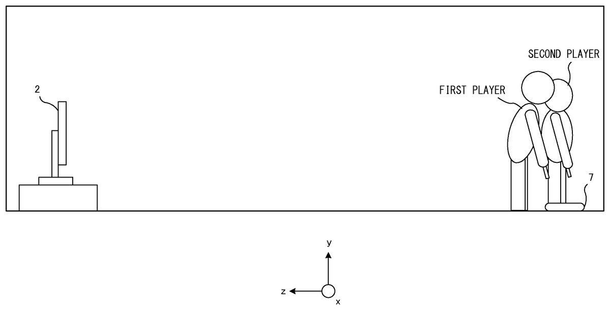
Next, examples of specific game flow and operation will be described. In the state shown inFIG. 7, for example, an image that informs start of the game (water scooping race) is displayed on the screen of the television2. Thereafter, each player, holding the controller5in his/her hand, moves toward the position where the terminal apparatus7is placed, as shown inFIG. 10.
Next, when each player arrives at the position where the terminal apparatus7is placed, as shown inFIG. 11, each player directs the front surface of the controller5at the terminal apparatus7(thereby, the marker section78of the terminal apparatus7is captured by the controller5). In other words, each player points to the LCD71with the controller5. At this time, the attitude of the controller5is that the front surface thereof faces substantially in the gravity direction (vertically downward) (hereinafter such an attitude is referred to as a downward attitude). At this time, no ladle object102is displayed on the television2, because the controller5is not capturing the marker device8on the television2side.
FIG. 12shows an example of a game image displayed on the terminal apparatus7at this time. InFIG. 12, the ladle object102corresponding to each player is displayed. On this screen, when each player performs an operation of raising the controller5upward, the player can scoop water from the stream object. Specifically, by changing the attitude of the controller5to the above-mentioned horizontal attitude, the player can scoop water. When the player has scooped water (when the attitude of the controller5has changed to the horizontal attitude), since the controller5is not capturing the marker section78of the terminal apparatus7, the ladle object102is erased from the image on the LCD71side (the terminal game image).
After each player has scooped water, each player, holding the controller5in his/her hand, moves to the position where the television2is placed, as shown inFIG. 13. In the exemplary embodiment, during this movement, change in the attitude of the controller5is detected to determine whether or not water spills from the controller5likened to the ladle. Therefore, each player needs to keep the controller5in the horizontal attitude as much as possible (so as to prevent the water from spilling out of the ladle) until arriving at the television2.
Then, as shown inFIG. 14, when each player has arrived at the television2, the ladle object102is displayed at a position, on the screen (in the virtual game space), corresponding to the pointing position of the controller. Then, as shown inFIG. 15, each player performs an operation of pointing to an upper portion of the container object101assigned to the player, and appropriately twisting the controller5(rotating the controller590 degrees about the z-axis, rightward or leftward). Thus, the player can pour the water into the container object101. It is noted that, regarding the amount of water at this time, the amount of water “spilled” while the player has moved from the terminal apparatus7to the television2is reflected. That is, the amount of water is obtained by subtracting the amount of “spilled” water.
Then, each player repeatedly moves back and forth between the television2and the terminal apparatus7, and thus the water scooping race game according to the exemplary embodiment is progressed.
By the way, in the above-mentioned game, it is needed to determine which of the screen of the television2and the screen of the LCD71of the terminal apparatus7is pointed to by the controller5. In particular, since the marker device8and the marker section78of the exemplary embodiment are basically devices that merely emit infrared light, each of the marker device8and the marker section78cannot be identified alone (that is, it is not configured to output a signal for identification, or the like). Therefore, even when the operation data transmitted from the controller5indicates that the controller5recognizes a marker (for example, the operation data includes an effective value as data of marker coordinates), such data is not sufficient to determine which of the marker device on the television2side and the marker section of the terminal apparatus7is recognized by the controller5. So, the exemplary embodiment adopts the configuration as follows. That is, the direction in which (the front surface of) the controller5faces is calculated based on acceleration data outputted from the controller5, and it is determined which of the television2and the terminal apparatus7is pointed to by the controller5.
Specifically, in the exemplary embodiment, based on the value of a z-axis acceleration of the acceleration data, it is determined whether the attitude of the controller5is the downward attitude or the horizontal attitude. Since the terminal apparatus7is placed in parallel to the floor as described above, the front surface of the controller5needs to be directed in the gravity direction in order to point to the terminal apparatus7with the controller5. Therefore, when the attitude of the controller5is that the front surface faces vertically downward or substantially vertically downward, it can be estimated that the player directs the controller5to the terminal apparatus7.
As described above, in the exemplary embodiment, the direction (attitude) of the controller5, that is, which of the television2and the terminal apparatus7is pointed to by the controller5can be determined based on the acceleration data. Thereby, in the game processing using the two screens placed as described above, even a controller of a simple configuration having only an acceleration sensor as a motion sensor enables the process in which the two screens are appropriately used.
Next, with reference toFIGS. 16 to 18, the operation of the game apparatus3according to the exemplary embodiment will be described in detail. First, various data used in the game processing will be described.FIG. 16is a diagram showing various data used in the game processing.FIG. 16shows main data stored in the memory12of the game apparatus3. As shown inFIG. 16, the memory12of the game apparatus3stores a game program201, operation data202, and processing data206. It is noted that the memory12stores, in addition to the data shown inFIG. 16, data desired for the game such as image data of various objects that appear in the game, audio data used in the game, and the like.
The game program201is stored in the memory12such that some or all of the game program201is loaded from the optical disc at an appropriate time after the game apparatus3has been powered on. It is noted that the game program201may be obtained from a flash memory or an external device of the game apparatus3which are not shown (via the Internet, for example), instead of from the optical disk. In addition, some of the game program201(for example, a program for calculating the attitudes of the controller5and/or the terminal apparatus7) may be stored in advance in the game apparatus3.
The operation data202is data representing an operation performed on the controller5by each user. InFIG. 16, the operation data202includes player-1operation data202aand player-2operation data202b(hereinafter, collectively referred to as “operation data”). The operation data202is transmitted from the controller5and obtained in the game apparatus3. The operation data202includes marker coordinate data203, operation button data204, and acceleration data205. It is noted that the memory12may store a predetermined number of operation data in order from the latest (most recently obtained) operation data.
The marker coordinate data203is data representing the coordinates calculated by the image processing circuit65dof the imaging information calculation section65, that is, data representing marker coordinates. The marker coordinates are represented by a two-dimensional coordinate system for representing a position, on a plane, corresponding to a captured image, and the marker coordinate data203represents coordinate values on the two-dimensional coordinate system. It is noted that, when the two markers8L and8R of the marker device8are captured by the image pickup device65c, two sets of marker coordinates are calculated, and the marker coordinate data203represents the two sets of marker coordinates. On the other hand, when either one of the markers8L and8R is placed outside the range that can be captured by the image pickup device65c, only the other one is captured by the image pickup device65c, and only one set of marker coordinates is calculated. As a result, the marker coordinate data203represents the one set of marker coordinates. Alternatively, when both the markers8L and8R are placed outside the range that can be captured by the image pickup device65c, no markers are captured by the image pickup device65c, and no marker coordinates are calculated. Therefore, the marker coordinate data203may represent two sets of marker coordinates, may represent one set of marker coordinates, or may represent that no marker coordinates are present (the same as above can be said for the marker section78of the terminal apparatus7).
It is noted that not the marker coordinate data but the image data itself of the captured image may be transmitted from the controller5to the game apparatus3. That is, the controller5may transmit either the marker coordinate data or the image data itself, as capturing data relating to the captured image by the image pickup device (image pickup element40). When receiving the image data of the captured image from the controller5, the game apparatus3may calculate the marker coordinates from the image data of the captured image, and store the marker coordinates as the marker coordinate data in the memory12.
The operation button data95is data representing the input state of each of the operation buttons provided on the controller5.
The acceleration data205is data representing the acceleration (acceleration vector) detected by the motion sensor63of the controller5. In the exemplary embodiment, the acceleration data205represents a three-dimensional acceleration consisting of components representing accelerations in the directions of the three axes, i.e., the x-axis, the y-axis, and the z-axis shown inFIG. 3. In another embodiment, the acceleration data205may represent accelerations in given one or more directions.
The processing data206is data used in game processing described later (FIG. 17). The processing data206includes player-1game data206a, player-2game data206b, and the like. It is noted that the processing data206includes, in addition to the data shown inFIG. 16, various data used in the game processing, such as data representing various parameters set on the respective objects.
The player-1game data206ais game data used for the first player. The player-2game data206bis game data used for the second player. Since the exemplary embodiment assumes the case where two players play a game, the game data for two players are shown. However, game data may be appropriately generated in accordance with the number of players who simultaneously play the game. The game data of each player includes operation mode data207, a water scooping flag208, and water amount data209.
The operation mode data207is data representing the operation mode of the controller5. In the exemplary embodiment, data representing any one of the following three operation modes is appropriately set in the operation mode data207by a process described later. In the exemplary embodiment, a television mode, a terminal apparatus mode, and a non-pointing mode are set. The television mode is a mode in which it is assumed that (the front surface of) the controller5is pointed to the television. The terminal apparatus mode is a mode in which it is assumed that the controller5is pointed to the terminal apparatus7. The non-pointing mode is a mode in which it is assumed that the controller5points neither to the television2nor to the terminal apparatus7. As an initial value at the start of the game, the non-pointing mode is set.
The water scooping flag208is a flag indicating whether or not the player is in the state where he/she performs an operation of scooping water with the controller5likened to a ladle and conveys the water to the container object. If the flag is ON, it means that the player is in the state where he/she scoops and conveys water (the state where water is in the ladle). The initial value of the flag is set to OFF. The water amount data209is a parameter indicating the amount of water that the player conveys. As described above, the amount of water decreases if “the water spills” while the player moves from the terminal apparatus7toward the television2.
Next, with reference to a flowchart ofFIG. 17, the flow of the game processing performed by the CPU11of the game apparatus3will be described. In the flowchart shown inFIG. 17, processes relating to determination as to which of the television2and the terminal apparatus7the controller5points to, which is performed based on the operation relating to the controller5, will be mainly described, while processes not directly related to the exemplary embodiment are not described in detail.
It is noted that the processes in the respective steps in the flowchart shown inFIG. 17are merely examples, and therefore, the order of the process steps may be changed as long as the same result is obtained. In addition, the values of the variables, and the thresholds used at determination steps are also merely examples, and other values may be used according to need. Further, in the exemplary embodiment, a description is given of the case where the CPU11performs the processes of the steps in the flowchart. However, a processor other than the CPU11or a dedicated circuit may perform the processes of some steps in the flowchart.
When the game processing is started, the CPU11performs an initial process (not shown). The initial process may include: constructing a virtual game space; locating each object that appears in the game space, at an initial position; and setting the initial values of the various parameters used in the game processing. After the initial process has been completed, a processing loop including a series of processes of steps S1through S13is performed, for each player, every predetermined period (one frame period) and repeated.
First, in step S1, the CPU11selects players to be the targets of the following processes (hereinafter referred to as “process target players”) from among unprocessed players. In the exemplary embodiment, the CPU11firstly selects the first player as a process target, and then selects the second player as a process target.
Next, in step S2, the CPU11obtains operation data from the controllers5of the process target players. The controller5repeatedly transmits the data outputted from the motion sensor63, the imaging information calculation section65, and the operation section61, to the game apparatus3, as the operation data. Upon sequentially receiving the data from the controller5, the game apparatus3sequentially stores the data in the memory12as the operation data. In step S2, the CPU11reads, from the memory12, the latest operation data202relating to the process target players. Since the terminal apparatus7is not used as an operation device in the exemplary embodiment, the following description will be made on assumption that the CPU11obtains no operation data from the terminal apparatus7.
Next, in step S3, the CPU11determines whether or not the controller5of each process target player recognizes the marker device8or the marker section78(hereinafter sometimes collectively referred to as “marker”). Specifically, the CPU11determines whether or not the marker device8or the marker section78is captured by the image pickup means (image pickup element65c) of the controller5. The CPU11can perform the determination in step S3by referring to the marker coordinate data203stored in the memory12. In the exemplary embodiment, when the marker coordinate data203represents two sets of marker coordinates, the CPU11determines that the marker device8or the marker section78is captured (that is, the marker is recognized). When the marker coordinate data203represents only one set of marker coordinates or represents no marker coordinates, the CPU11determines that the marker device8or the marker section78is not captured (no marker is recognized).
When determining that no marker is recognized (NO in step S3), the CPU11sets the “non-pointing mode” in the operation mode data207of the process target player, in step S9. Thereafter, the process goes to step S11described later. On the other hand, when determining that the marker is recognized (YES in step S3), the CPU11determines, based on the acceleration of the controller5, whether or not the attitude of the controller5of the process target player can be regarded as the horizontal attitude, in step S4. Specifically, the CPU11reads the acceleration data205from the memory12, and determines whether or not the value of the Z-axis acceleration of the acceleration data205is smaller than 0.2. In the state where the controller5is substantially stationary, the acceleration applied to the controller5is equal to the gravitational acceleration. Accordingly, in this state, the direction (attitude) of the controller5with respect to the direction of the detected gravitational acceleration (gravity direction) can be calculated based on the acceleration data205. In the exemplary embodiment, the correspondence relation between the value of the Z-axis acceleration and the direction of the front surface of the controller5is as shown inFIG. 18. First, the value of the Z-axis acceleration is in a range of +1 to −1. When the front surface of the controller5(the Z-axis positive direction in the local coordinate system of the controller) faces vertically downward, the Z-axis acceleration is “+1”. When the front surface of the controller5faces vertically upward, the Z-axis acceleration is “−1”. When the front surface of the controller5is in the horizontal state, the Z-axis acceleration is “0”. Based on the above-mentioned relation, the CPU11determines whether or not the value of the z-axis acceleration is smaller than 0.2. When the value of the z-axis acceleration is smaller than 0.2, it is considered that the controller5is in the horizontal attitude or in the attitude that can be regarded as substantially horizontal (in other words, it is considered that the controller5is at least not in the downward attitude).
When determining that the value of the Z-axis acceleration is smaller than 0.2 (YES in step S4), the CPU11sets the “television mode” in the operation mode data207of the process target player, in step S10. Thereafter, the process goes to step S11described later. On the other hand, when the value of the Z-axis acceleration is not smaller than 0.2 (NO in step S4), the CPU11determines whether or not the current operation mode is the “terminal apparatus mode”, with reference to the operation mode data207, in step S5. Based on the result of the determination, when the current operation mode is not the “terminal apparatus mode” (NO in step S5), it is considered that the player is in such a state that he/she has moved from the television2to the position of the terminal apparatus7and has just directed the controller5to the terminal apparatus7. In this case, in step S6, the CPU11determines whether or not the controller5is in the downward attitude, based on the acceleration of the controller5. In other words, the CPU11determines whether or not the terminal apparatus7is pointed to by the controller5. Specifically, the CPU11reads the acceleration data205from the memory12, and determines whether or not the value of the Z-axis acceleration of the acceleration data205is larger than 0.8. When determining that the value of the Z-axis acceleration is larger than 0.8 (YES in step S6), the CPU11sets the “terminal apparatus mode” in the operation mode data207, in step S7. Thereafter, the process goes to step S11described later. On the other hand, when the value of the Z-axis acceleration is not larger than 0.8 (NO in step S6), the CPU11sets the “non-pointing mode” in the operation mode data207, in step S9. Thereafter, the process goes to step S11described later.
On the other hand, when determining in step S5that the current operation mode is the “terminal apparatus mode” (YES in step S5), the CPU11determines whether or not the value of the Z-axis acceleration is larger than 0.7, in step S8. Although the purpose of this determination is basically the same as the purpose of the determination in step S6, the threshold for the determination in step S8is reduced a little. The reason is as follows. When the current operation mode is already the “terminal apparatus mode”, it is considered that the state where the controller5points to the terminal apparatus7continues (for example, the water scooping operation continues). Then, in order to enhance the operability by making the operation mode hard to change (by making the downward attitude easy to be maintained), the determination is performed with the threshold being reduced a little. Thereby, it is possible to avoid the situation where the terminal apparatus mode is canceled during the water scooping operation, and the water scooping operation does not go well. Based on the result of the determination, when the value of the Z-axis acceleration is larger than 0.7 (YES in step S8), the process in step S7is performed. On the other hand, when the value of the Z-axis acceleration is not larger than 0.7 (NO in step S8), the process in step S9is performed.
Next, in step S11, the CPU11performs a game process according to the operation mode. Specifically, any of the following game processes is performed on the process target player.
[A. Process in Terminal Apparatus Mode]
When the marker is recognized and the operation mode data207represents the terminal apparatus mode, the CPU11calculates the pointing position on the LCD71based on the marker coordinate data203. Then, the CPU11places, at the position, the ladle object102corresponding to the process target player. At this time, the CPU11appropriately calculates the attitude of the controller5based on the acceleration data and/or the marker coordinate data, and reflects the attitude of the controller5in the attitude of the ladle object102.
Further, when the water scooping operation is performed (that is, when the determination result is NO in step S8), the CPU11turns on the water scooping flag208, and sets a predetermined value, for example, “100”, in the water amount data209. At this time, a sound effect indicating that water is scooped may be output from the loudspeakers of the controller5and the terminal apparatus7.
In addition, various game processes based on the assumption that the controller5points to the terminal apparatus7are appropriately performed.
[B. Process in Non-Pointing Mode]
When the operation mode data207represents the non-pointing mode, it is estimated that the controller5points neither to the television2nor to the terminal apparatus7. At this time, the CPU11temporarily erases the ladle object102from the virtual game space so that the ladle object102is not included in the television game image or the terminal game image.
Further, with reference to the water scooping flag208, the CPU11determines whether or not the process target player is moving from the terminal apparatus7toward the television2. When the water scooping flag208is ON, it is estimated that the process target player is moving. At this time, the CPU11determines whether or not “vibration” occurs in the controller5, based on the acceleration data205obtained from the controller5. When such “vibration” occurs, the CPU11calculates the magnitude of the “vibration”. The value of the water amount data209is gradually decreased in accordance with the magnitude of the “vibration”. That is, a process is performed which reproduces a situation where water spills from the ladle in accordance with vibration of the ladle while the player is conveying water. In addition, in this process, a sound effect indicating that water spills from the ladle may be output from the loudspeaker of the controller5.
In addition, various game processes based on the assumption that the controller5points neither to the television2nor to the terminal apparatus7are appropriately performed.
[C. Process in Television Mode]
When the operation mode data207represents the “television mode”, it is estimated that the controller5points to the television2. At this time, the CPU11calculates pointing coordinates on the screen, based on the marker coordinate data203obtained from the controller5. Then, the CPU11places the ladle object102of the process target player at a position, in the virtual game space, corresponding to the pointing coordinates.
Further, the CPU11determines whether or not the water scooping flag208is ON. When the water scooping flag208is ON, the CPU11detects change in the attitude of the controller5, based on the acceleration data205and/or the marker coordinate data203. If attitude change (rotation about the Z-axis) like pouring of water into the container object occurs, the CPU11performs a process for displaying the state where an amount of the water object corresponding to the value of the water amount data209at this time is poured in the container object101. In association with this process, the CPU11turns off the water scooping flag208, and sets “0” in the water amount data209.
In addition, various game processes based on the assumption that the controller5points to the television2are appropriately performed.
As described above, in step S11, the game process according to the operation mode is appropriately performed, and reflected in the state of the virtual game space.
Next, in step S12, the CPU11determines whether or not the above-mentioned processes have been performed on all the players. When unprocessed player(s) still remains (NO in step S12), the CPU11returns to step S1to repeat the processes. On the other hand, when all the players have been processed (YES in step S12), in step S13, the CPU11generates a television game image and a terminal game image representing the virtual game space in which the game process in step S11is reflected, and displays the images on the television2and the LCD71, respectively.
This is the end of the description of the game processing according to the exemplary embodiment.
As described above, in the exemplary embodiment, the game using the two screens is played such that one of the two screens is placed so as to face in a direction along the gravity direction axis, while the other screen is placed so as to face in a direction along an axis different from the gravity direction axis (preferably, an axis perpendicular to the gravity direction axis). Then, which of the two screens thus placed is pointed is determined based on the acceleration data. Therefore, it is possible to perform the game processing in which the two screens placed as described above are appropriately used, by using the controller of the simple configuration such as a controller having an acceleration sensor, and thus the players are provided with a new way to play. In particular, by placing the television2and the terminal apparatus7at positions somewhat distant from each other, it is possible to provide the players with a new way to play that causes the players to perform dynamic actions.
In the exemplary embodiment, the terminal apparatus7is placed so that the LCD71faces upward. However, the terminal apparatus7may be placed at a position above the head of a player such that the LCD71faces vertically downward. In this case, determination as to whether the front surface of the controller5faces upward is performed instead of determining as to whether the front surface of the controller5faces downward in the exemplary embodiment.
Further, in the exemplary embodiment, the three operation modes, i.e., the television mode, the terminal apparatus mode, and the non-pointing mode, are adopted. However, the embodiment is not limited thereto. For example, only two operation modes, such as the television mode and the terminal apparatus mode, may be adopted. That is, game processing may be performed which is based on the assumption that the controller5always points to either the television2or the terminal apparatus7.
Further, in the exemplary embodiment, it is determined which of the television2and the terminal apparatus7is pointed to by the controller5, and a series of processes for performing game processing according to the determination result is performed in a single apparatus. In another exemplary embodiment, however, the series of processes may be performed in an information processing system that includes a plurality of information processing apparatuses. For example, in an information processing system that includes the game apparatus3and a server side apparatus capable of communicating with the game apparatus3via a network, a part of the series of processes may be performed by the server side apparatus. Alternatively, in an information processing system that includes the game apparatus3and a server side apparatus capable of communicating with the game apparatus3via a network, a main process of the series of the processes may be performed by the server side apparatus, and a part of the series of the processes may be performed by the game apparatus3. Still alternatively, in the information processing system, a server side system may include a plurality of information processing apparatuses, and a process to be performed in the server side system may be divided and performed by the plurality of information processing apparatuses.
Claims
- A game system which performs a predetermined game process, based on a position that is pointed to, on a screen of a display, by an operation device including a predetermined motion sensor, the game system comprising: a first display device which is placed so that a display screen thereof faces in a direction along a gravity direction axis;a second display device that is placed so that a display screen thereof faces in a direction along a predetermined axis direction perpendicular to the gravity direction axis, and a computer processor configured to perform at least: attitude calculation for calculating an attitude of the operation device, based on data outputted from the motion sensor;determination for determining which of the screen of the first display device and the screen of the second display device is pointed to by the operation device, based on the calculated attitude;pointing processing for performing a process of pointing to a predetermined position on either the screen of the first display device or the screen of the second display device, based on a result of the determination;and game processing for performing the predetermined game process, based on the pointed position, wherein the game processing causes a player to perform a predetermined operation on the operation device in the state where the operation device is pointing to the screen of the first display device, thereby to perform a game process in which a predetermined object displayed on the screen of the first display device is taken by the operation device, and thereafter, the game processing causes the player to perform a predetermined operation in the state where the operation device is pointing to the second display device, thereby to perform a game process in which the object is moved into and displayed on the screen of the second display device.
- The game system according to claim 1 , wherein the determination determines whether the calculated attitude of the operation device is a first attitude in which, among outer surfaces of a casing of the operation device, a surface that is opposed to or substantially opposed to the display screen of the first display device or the display screen of the second display device when a player points to the display screen, faces in a direction along the gravity direction axis or a direction substantially along the gravity direction axis, or a second attitude in which the surface that is opposed to or substantially opposed to the display screen faces in a direction along a predetermined axis direction perpendicular to the gravity direction axis or a direction substantially along the predetermined axis direction, and the determination determines, when the attitude of the operation device is the first attitude, that the operation device points to the first display device, and determines, when the attitude of the operation device is the second attitude, that the operation device points to the second display device.
- The game system according to claim 2 , wherein the motion sensor is an acceleration sensor, and the attitude calculation determines the attitude of the operation device, based on acceleration data obtained from the acceleration sensor.
- The game system according to claim 1 , wherein the operation device further includes an image pickup, the game system further includes marker sections provided corresponding to the plurality of display devices, respectively, each of the marker sections is installed such that its direction is the same as the direction of the screen of the display device corresponding to the marker section, and the pointing processing includes pointed position calculation for calculating a pointed position on the screen, based on the position of the marker section in an image captured by the image pickup.
- The game system according to claim 4 , wherein each of the marker sections includes a light emitting member, the computer processor of the game system further performs lighting control for controlling lighting of the marker sections, the first display device is a display device that stores, in its casing, the marker section, and the second display device is a television, and the marker section corresponding to the television is installed in the vicinity of the television.
- The game system according to claim 1 , wherein the game processing includes: attitude change detection detecting change in the attitude of the operation device, during a period from when the game process in which the predetermined object displayed on the screen of the first display device is taken by the operation device is performed to when the player performs the predetermined operation in the state where the operation device is pointing to the second display device;parameter change for changing a predetermined parameter associated with the predetermined object, in accordance with a result of the detection by the attitude change detection;and reflection for, when the predetermined object is displayed on the screen of the second display device, reflecting the parameter changed by the parameter change, in the display of the object.
- A non-transitory computer-readable storage medium having stored thereon a game program performed by a computer of a game system which performs a predetermined game process based on a position pointed to on a screen of a display by an operation device having a predetermined motion sensor, the game program causing the computer to perform at least: attitude calculation for calculating an attitude of the operation device, based on data outputted from the motion sensor;determination for determining, based on the calculated attitude, which of a display screen of a first display device that is placed so that the display screen faces in a direction along a gravity direction axis, and a display screen of a second display that is placed so that the display screen faces in a direction along a predetermined axis direction perpendicular to the gravity direction axis, is pointed to by the operation device;pointing processing for performing a process of pointing to a predetermined position on either the screen of the first display device or the screen of the second display device, based on a result of the determination;and game processing for performing the predetermined game process, based on the pointed position, wherein the game processing causes a player to perform a predetermined operation on the operation device in the state where the operation device is pointing to the screen of the first display device, thereby to perform a game process in which a predetermined object displayed on the screen of the first display device is taken by the operation device, and thereafter, the games processing causes the player to perform a predetermined operation in the state where the operation device is pointing to the second display device, thereby to perform a game process in which the object is moved into and displayed on the screen of the second display device.
- A game processing method for controlling a game system with a movement sensor, light emitting members, an image pickup element and a computer processor coupled to the movement sensor, the light emitting members, and the image pickup element, wherein the game system performs a predetermined game process based on a position pointed to on a screen of a display device by an operation device including the movement sensor, the game processing method comprising: responsive to reception of an electrical signal generated by the movement sensor, calculating, via the computer processor, an attitude of the operation device, based on data outputted from the movement sensor;determining, based on the calculated attitude, which of a display screen of a first display device that is placed so that the display screen faces in a direction along a gravity direction axis, and a display screen of a second display that is placed so that the display screen faces in a direction along a predetermined axis direction perpendicular to the gravity direction axis, is pointed to by the operation device, by programmatically comparing, using the computer processor, the data outputted from the movement sensor to predetermined thresholds, and generating an electronic message that includes an indication of the display screen pointed to by the operation device;performing a process of pointing to a predetermined position on either the screen of the first display device or the screen of the second display device, based on the generated electronic message;and performing the predetermined game process, based on the pointed position, wherein the performing the predetermined game process causes a player to perform a predetermined operation on the operation device in the state where the operation device is pointing to the screen of the first display device, thereby to perform a game process in which a predetermined object displayed on the screen of the first display device is taken by the operation device, and thereafter, the performing the predetermined game process causes the player to perform a predetermined operation in the state where the operation device is pointing to the second display device, thereby to perform a game process in which the object is moved into and displayed on the screen of the second display device.
- A game apparatus which obtains operation data from an operation device including a predetermined motion sensor, and outputs a predetermined game image generated by a predetermined game process based on the operation data, to each of display screens of a first display device and a second display device which are placed so that the directions of the screens are different from each other, the game, wherein the first display device is placed so that the display screen thereof faces in a direction along a gravity direction axis, and the second display device is placed so that the display screen thereof faces in a direction along a predetermined axis direction perpendicular to the gravity direction axis, and the game apparatus includes a computer processor configured to perform at least: attitude calculation for calculating an attitude of the operation device, based on data outputted from the motion sensor;determination for determining which of the screen of the first display device and the screen of the second display device is pointed to by the operation device, based on the calculated attitude;pointing processing for performing a process of pointing to a predetermined position on either the screen of the first display device or the screen of the second display device, based on a result of the determination;and game processing for performing the predetermined game process, based on the pointed position, wherein the game processing causes a player to perform a predetermined operation on the operation device in the state where the operation device is pointing to the screen of the first display device, thereby to perform a game process in which a predetermined object displayed on the screen of the first display device is taken by the operation device, and thereafter, the game processing causes the player to perform a predetermined operation in the state where the operation device is pointing to the second display device, thereby to perform a game process in which the object is moved into and displayed on the screen of the second display device.
Disclaimer: Data collected from the USPTO and may be malformed, incomplete, and/or otherwise inaccurate.