U.S. Pat. No. 9,095,774
COMPUTER-READABLE STORAGE MEDIUM HAVING PROGRAM STORED THEREIN, APPARATUS, SYSTEM, AND METHOD, FOR PERFORMING GAME PROCESSING
AssigneeNintendo Co Ltd; HAL Laboratory Inc
Issue DateJune 14, 2011
Illustrative Figure
Abstract
A storage medium has stored therein a game program that in game processing, controls a correlation between a player object and a non-player object through a virtual surface that is set on the basis of a marker for generating a superimposed image by combining a real world image and a virtual world image. The game program causes a computer of an apparatus, which includes a display device for providing the superimposed image to a user and an imaging section for taking an image of the marker, to operate as predetermined means.
Description
DESCRIPTION OF THE PREFERRED EMBODIMENTS (Example of Structure of Game Apparatus) Hereinafter, a game apparatus according to one exemplified embodiment of the present invention will be described.FIGS. 1 to 3are each a plan view of an outer appearance of a game apparatus10. The game apparatus10is a hand-held game apparatus, and is configured to be foldable as shown inFIGS. 1 to 3.FIGS. 1 and 2show the game apparatus10in an opened state, andFIG. 3shows the game apparatus10in a closed state.FIG. 1is a front view of the game apparatus10in the opened state, andFIG. 2is a right side view of the game apparatus10in the opened state. The game apparatus10is able to take an image by means of an imaging section, display the taken image on a screen, and store data of the taken image. The game apparatus10can execute a game program which is stored in an exchangeable memory card or a game program which is received from a server or another game apparatus, and can display, on the screen, an image generated by computer graphics processing, such as an image taken by a virtual camera set in a virtual space, for example. Initially, an external structure of the game apparatus10will be described with reference toFIGS. 1 to 3. The game apparatus10includes a lower housing11and an upper housing21as shown inFIGS. 1 to 3. The lower housing11and the upper housing21are connected to each other so as to be openable and closable (foldable). In the present embodiment, the lower housing11and the upper housing21are each formed in a horizontally long plate-like rectangular shape, and are connected to each other at long side portions thereof so as to be pivotable with respect to each other. As shown inFIGS. 1 and 2, projections11A each of which projects in a direction orthogonal to an inner side surface (main surface)11B of the ...
DESCRIPTION OF THE PREFERRED EMBODIMENTS
(Example of Structure of Game Apparatus)
Hereinafter, a game apparatus according to one exemplified embodiment of the present invention will be described.FIGS. 1 to 3are each a plan view of an outer appearance of a game apparatus10. The game apparatus10is a hand-held game apparatus, and is configured to be foldable as shown inFIGS. 1 to 3.FIGS. 1 and 2show the game apparatus10in an opened state, andFIG. 3shows the game apparatus10in a closed state.FIG. 1is a front view of the game apparatus10in the opened state, andFIG. 2is a right side view of the game apparatus10in the opened state. The game apparatus10is able to take an image by means of an imaging section, display the taken image on a screen, and store data of the taken image. The game apparatus10can execute a game program which is stored in an exchangeable memory card or a game program which is received from a server or another game apparatus, and can display, on the screen, an image generated by computer graphics processing, such as an image taken by a virtual camera set in a virtual space, for example.
Initially, an external structure of the game apparatus10will be described with reference toFIGS. 1 to 3. The game apparatus10includes a lower housing11and an upper housing21as shown inFIGS. 1 to 3. The lower housing11and the upper housing21are connected to each other so as to be openable and closable (foldable). In the present embodiment, the lower housing11and the upper housing21are each formed in a horizontally long plate-like rectangular shape, and are connected to each other at long side portions thereof so as to be pivotable with respect to each other.
As shown inFIGS. 1 and 2, projections11A each of which projects in a direction orthogonal to an inner side surface (main surface)11B of the lower housing11are provided at the upper long side portion of the lower housing11, whereas a projection21A which projects from the lower side surface of the upper housing21in a direction orthogonal to the lower side surface of the upper housing21is provided at the lower long side portion of the upper housing21. Since the projections11A of the lower housing11and the projection21A of the upper housing21are connected to each other, the lower housing11and the upper housing21are foldably connected to each other.
(Description of Lower Housing)
Initially, a structure of the lower housing11will be described. As shown inFIGS. 1 to 3, in the lower housing11, a lower LCD (Liquid Crystal Display)12, a touch panel13, operation buttons14A to14L (FIG. 1,FIG. 3), an analog stick15, an LED16A and an LED16B, an insertion opening17, and a microphone hole18are provided. Hereinafter, these components will be described in detail.
As shown inFIG. 1, the lower LCD12is accommodated in the lower housing11. The lower LCD12has a horizontally long shape, and is located such that a long side direction thereof corresponds to a long side direction of the lower housing11. The lower LCD12is positioned at the center of the lower housing11. The lower LCD12is provided on the inner side surface (main surface) of the lower housing11, and a screen of the lower LCD12is exposed at an opening of the lower housing11. When the game apparatus10is not used, the game apparatus10is in the closed state, thereby preventing the screen of the lower LCD12from becoming unclean and damaged. The number of pixels of the lower LCD12may be, for example, 256 dots×192 dots (the longitudinal line×the vertical line). The lower LCD12is a display device for displaying an image in a planar manner (not in a stereoscopically visible manner), which is different from the upper LCD22as described below. Although an LCD is used as a display device in the present embodiment, any other display device such as a display device using an EL (Electro Luminescence), or the like may be used. In addition, a display device having any resolution may be used as the lower LCD12.
As shown inFIG. 1, the game apparatus10includes the touch panel13as an input device. The touch panel13is mounted on the screen of the lower LCD12. In the present embodiment, the touch panel13may be, but is not limited to, a resistive film type touch panel. A touch panel of any type such as electrostatic capacitance type may be used. In the present embodiment, the touch panel13has the same resolution (detection accuracy) as that of the lower LCD12. However, the resolution of the touch panel13and the resolution of the lower LCD12may not necessarily be the same. Further, the insertion opening17(indicated by dashed line inFIG. 1andFIG. 3(d)) is provided on the upper side surface of the lower housing11. The insertion opening17is used for accommodating a touch pen28which is used for performing an operation on the touch panel13. Although an input on the touch panel13is usually made by using the touch pen28, a finger of a user may be used for making an input on the touch panel13, in addition to the touch pen28.
The operation buttons14A to14L are each an input device for making a predetermined input. As shown inFIG. 1, among operation buttons14A to14L, a cross button14A (a direction input button14A), a button14B, a button14C, a button14D, a button14E, a power button14F, a selection button14J, a HOME button14K, and a start button14L are provided on the inner side surface (main surface) of the lower housing11. The cross button14A is cross-shaped, and includes buttons for indicating an upward, a downward, a leftward, or a rightward direction. The button14B, button14C, button14D, and button14E are positioned so as to form a cross shape. The button14A to14E, the selection button14J, the HOME button14K, and the start button14L are assigned functions, respectively, in accordance with a program executed by the game apparatus10, as necessary. For example, the cross button14A is used for selection operation and the like, and the operation buttons14B to14E are used for, for example, determination operation and cancellation operation. The power button14F is used for powering the game apparatus10on/off.
The analog stick15is a device for indicating a direction, and is provided to the left of the lower LCD12in an upper portion of the inner side surface of the lower housing11. As shown inFIG. 1, the cross button14A is provided to the left of the lower LCD12in the lower portion of the lower housing11. That is, the analog stick15is provided above the cross button14A. The analog stick15and the cross button14A are positioned so as to be operated by a thumb of a left hand with which the lower housing is held. Further, the analog stick15is provided in the upper area, and thus the analog stick15is positioned such that a thumb of a left hand with which the lower housing11is held is naturally positioned on the position of the analog stick15, and the cross button14A is positioned such that the thumb of the left hand is positioned on the position of the cross button14A when the thumb of the left hand is slightly moved downward from the analog stick15. The analog stick15has a top, corresponding to a key, which slides parallel to the inner side surface of the lower housing11. The analog stick15acts in accordance with a program executed by the game apparatus10. For example, when a game in which a predetermined object appears in a three-dimensional virtual space is executed by the game apparatus10, the analog stick15acts as an input device for moving the predetermined object in the three-dimensional virtual space. In this case, the predetermined object is moved in a direction in which the top corresponding to the key of the analog stick15slides. As the analog stick15, a component which enables an analog input by being tilted by a predetermined amount, in any direction, such as the upward, the downward, the rightward, the leftward, or the diagonal direction, may be used.
Four buttons, that is, the button14B, the button14C, the button14D, and the button14E, which are positioned so as to form a cross shape, are positioned such that a thumb of a right hand with which the lower housing11is held is naturally positioned on the positions of the four buttons. Further, the four buttons and the analog stick15sandwich the lower LCD12, so as to be bilaterally symmetrical in position with respect to each other. Thus, depending on a game program, for example, a left-handed person can make a direction instruction input by using these four buttons.
Further, the microphone hole18is provided on the inner side surface of the lower housing11. Under the microphone hole18, a microphone (seeFIG. 6) is provided as a sound input device described below, and the microphone detects for a sound from the outside of the game apparatus10.
FIG. 3(a) is a left side view of the game apparatus10in the closed state.FIG. 3(b) is a front view of the game apparatus10in the closed state.FIG. 3(c) is a right side view of the game apparatus10in the closed state.FIG. 3(d) is a rear view of the game apparatus10in the closed state. As shown inFIG. 3(b) andFIG. 3(d), an L button14G and an R button14H are provided on the upper side surface of the lower housing11The L button14G is positioned on the left end portion of the upper side surface of the lower housing11and the R button14H is positioned on the right end portion of the upper side surface of the lower housing11. The L button14G and the R button14H can act, for example, as shutter buttons (imaging instruction buttons) of the imaging section. Further, as shown inFIG. 3(a), a sound volume button14I is provided on the left side surface of the lower housing11. The sound volume button14I is used for adjusting a sound volume of a speaker of the game apparatus10.
As shown inFIG. 3(a), a cover section11C is provided on the left side surface of the lower housing11so as to be openable and closable. Inside the cover section11C, a connector (not shown) is provided for electrically connecting between the game apparatus10and an external data storage memory45. The external data storage memory45is detachably connected to the connector. The external data storage memory45is used for, for example, recording (storing) data of an image taken by the game apparatus10. The connector and the cover section11C may be provided on the right side surface of the lower housing11.
Further, as shown inFIG. 3(d), an insertion opening11D through which an external memory44having a game program stored therein is inserted is provided on the upper side surface of the lower housing11. A connector (not shown) for electrically connecting between the game apparatus10and the external memory44in a detachable manner is provided inside the insertion opening11D. A predetermined game program is executed by connecting the external memory44to the game apparatus10. The connector and the insertion opening11D may be provided on another side surface (for example, the right side surface) of the lower housing11.
Further, as shown inFIG. 1andFIG. 3(c), a first LED16A for notifying a user of an ON/OFF state of a power supply of the game apparatus10is provided on the lower side surface of the lower housing11, and a second LED16B for notifying a user of an establishment state of a wireless communication of the game apparatus10is provided on the right side surface of the lower housing11. The game apparatus10can make wireless communication with other devices, and the second LED16B is lit up when the wireless communication is established. The game apparatus10has a function of connecting to a wireless LAN in a method based on, for example, IEEE802.11.b/g standard. A wireless switch19for enabling/disabling the function of the wireless communication is provided on the right side surface of the lower housing11(seeFIG. 3(c)).
A rechargeable battery (not shown) acting as a power supply for the game apparatus10is accommodated in the lower housing11, and the battery can be charged through a terminal provided on a side surface (for example, the upper side surface) of the lower housing11.
(Description of Upper Housing)
Next, a structure of the upper housing21will be described. As shown inFIGS. 1 to 3, in the upper housing21, an upper LCD (Liquid Crystal Display)22, an outer imaging section23(an outer imaging section (left)23aand an outer imaging section (right)23b), an inner imaging section24, a 3D adjustment switch25, and a 3D indicator26are provided. Hereinafter, theses components will be described in detail.
As shown inFIG. 1, the upper LCD22is accommodated in the upper housing21. The upper LCD22has a horizontally long shape, and is located such that a long side direction thereof corresponds to a long side direction of the upper housing21. The upper LCD22is positioned at the center of the upper housing21. The area of a screen of the upper LCD22is set so as to be greater than the area of the screen of the lower LCD12. Further, the screen of the upper LCD22is horizontally elongated as compared to the screen of the lower LCD12. Specifically, a rate of the horizontal width in the aspect ratio of the screen of the upper LCD22is set so as to be greater than a rate of the horizontal width in the aspect ratio of the screen of the lower LCD12.
The screen of the upper LCD22is provided on the inner side surface (main surface)21B of the upper housing21, and the screen of the upper LCD22is exposed at an opening of the upper housing21. Further, as shown inFIG. 2, the inner side surface of the upper housing21is covered with a transparent screen cover27. The screen cover27protects the screen of the upper LCD22, and integrates the upper LCD22and the inner side surface of the upper housing21with each other, thereby achieving unity. The number of pixels of the upper LCD22may be, for example, 640 dots×200 dots (the horizontal line×the vertical line). Although, in the present embodiment, the upper LCD22is an LCD, a display device using an EL (Electro Luminescence), or the like may be used. In addition, a display device having any resolution may be used as the upper LCD22.
The upper LCD22is a display device capable of displaying a stereoscopically visible image. Further, in the present embodiment, an image for a left eye and an image for a right eye are displayed by using substantially the same display area. Specifically, the upper LCD22may be a display device using a method in which the image for a left eye and the image for a right eye are alternately displayed in the horizontal direction in predetermined units (for example, every other line). Alternatively, a display device using a method in which the image for a left eye and the image for a right eye are displayed alternately in a time division manner may be used. Further, in the present embodiment, the upper LCD22is a display device capable of displaying an image which is stereoscopically visible with naked eyes. A lenticular lens type display device or a parallax barrier type display device is used which enables the image for a left eye and the image for a right eye, which are alternately displayed in the horizontal direction, to be separately viewed by the left eye and the right eye, respectively. In the present embodiment, the upper LCD22of a parallax barrier type is used. The upper LCD22displays, by using the image for a right eye and the image for a left eye, an image (a stereoscopic image) which is stereoscopically visible with naked eyes. That is, the upper LCD22allows a user to view the image for a left eye with her/his left eye, and the image for a right eye with her/his right eye by utilizing a parallax barrier, so that a stereoscopic image (a stereoscopically visible image) exerting a stereoscopic effect for a user can be displayed. Further, the upper LCD22may disable the parallax barrier. When the parallax barrier is disabled, an image can be displayed in a planar manner (it is possible to display a planar visible image which is different from a stereoscopically visible image as described above. Specifically, a display mode is used in which the same displayed image is viewed with a left eye and a right eye). Thus, the upper LCD22is a display device capable of switching between a stereoscopic display mode for displaying a stereoscopically visible image and a planar display mode (for displaying a planar visible image) for displaying an image in a planar manner. The switching of the display mode is performed by the 3D adjustment switch25described below.
Two imaging sections (23aand23b) provided on the outer side surface (the back surface reverse of the main surface on which the upper LCD22is provided)21D of the upper housing21are generically referred to as the outer imaging section23. The imaging directions of the outer imaging section (left)23aand the outer imaging section (right)23bare each the same as the outward normal direction of the outer side surface21D. Further, these imaging sections are each designed so as to be positioned in a direction which is opposite to the normal direction of the display surface (inner side surface) of the upper LCD22by 180 degrees. Specifically, the imaging direction of the outer imaging section (left)23aand the imaging direction of the outer imaging section (right)23bare parallel to each other. The outer imaging section (left)23aand the outer imaging section (right)23bcan be used as a stereo camera depending on a program executed by the game apparatus10. Further, depending on a program, when any one of the two outer imaging sections (23aand23b) is used alone, the outer imaging section23may be used as a non-stereo camera. Further, depending on a program, images taken by the two outer imaging sections (23aand23b) may be combined with each other or may compensate for each other, thereby enabling imaging using an extended imaging range. In the present embodiment, the outer imaging section23is structured so as to include two imaging sections, that is, the outer imaging section (left)23aand the outer imaging section (right)23b. Each of the outer imaging section (left)23aand the outer imaging section (right)23bincludes an imaging device, such as a CCD image sensor or a CMOS image sensor, having a common predetermined resolution, and a lens. The lens may have a zooming mechanism.
As indicated by dashed lines inFIG. 1and by solid lines inFIG. 3(b), the outer imaging section (left)23aand the outer imaging section (right)23bforming the outer imaging section23are aligned so as to be parallel to the horizontal direction of the screen of the upper LCD22. Specifically, the outer imaging section (left)23aand the outer imaging section (right)23bare positioned such that a straight line connecting between the two imaging sections is parallel to the horizontal direction of the screen of the upper LCD22. Reference numerals23aand23bwhich are indicated as dashed lines inFIG. 1represent the outer imaging section (left)23aand the outer imaging section (right)23b, respectively, which are positioned on the outer side surface reverse of the inner side surface of the upper housing21. As shown inFIG. 1, when a user views the screen of the upper LCD22from the front thereof, the outer imaging section (left)23ais positioned to the left of the upper LCD22and the outer imaging section (right)23bis positioned to the right of the upper LCD22. When a program for causing the outer imaging section23to function as a stereo camera is executed, the outer imaging section (left)23atakes an image for a left eye, which is viewed by a left eye of a user, and the outer imaging section (right)23btakes an image for a right eye, which is viewed by a right eye of the user. A distance between the outer imaging section (left)23aand the outer imaging section (right)23bis set so as to be approximately the same as a distance between both eyes of a person, that is, may be set so as to be within a range from 30 mm to 70 mm, for example, However, the distance between the outer imaging section (left)23aand the outer imaging section (right)23bis not limited to a distance within the range described above.
In the present embodiment, the outer imaging section (left)23aand the outer imaging section (right)23bare secured to the housing, and the imaging directions thereof cannot be changed.
Further, the outer imaging section (left)23aand the outer imaging section (right)23bare positioned to the left and to the right, respectively, of the upper LCD22(on the left side and the right side, respectively, of the upper housing21) so as to be horizontally symmetrical with respect to the center of the upper LCD22. Specifically, the outer imaging section (left)23aand the outer imaging section (right)23bare positioned so as to be symmetrical with respect to a line which divides the upper LCD22into two equal parts, that is, the left part and the right part. Further, the outer imaging section (left)23aand the outer imaging section (right)23bare positioned at positions which are reverse of positions above the upper edge of the screen of the upper LCD22and which are on the upper portion of the upper housing21in an opened state. Specifically, when the upper LCD22is projected on the outer side surface of the upper housing21, the outer imaging section (left)23aand the outer imaging section (right)23bare positioned, on the outer side surface of the upper housing21, at a position above the upper edge of the screen of the upper LCD22having been projected.
As described above, the two imaging sections (23aand23b) of the outer imaging section23are positioned to the left and the right of the upper LCD22so as to be horizontally symmetrical with respect to the center of the upper LCD22. Therefore, when a user views the upper LCD22from the front thereof, the imaging direction of the outer imaging section23can be the same as the direction of the line of sight of the user. Further, the outer imaging section23is positioned at a position reverse of a position above the upper edge of the screen of the upper LCD22. Therefore, the outer imaging section23and the upper LCD22do not interfere with each other inside the upper housing21. Therefore, the upper housing21may have a reduced thickness as compared to a case where the outer imaging section23is positioned on a position reverse of a position of the screen of the upper LCD22.
The inner imaging section24is positioned on the inner side surface (main surface)21B of the upper housing21, and acts as an imaging section which has an imaging direction which is the same direction as the inward normal direction of the inner side surface. The inner imaging section24includes an imaging device, such as a CCD image sensor and a CMOS image sensor, having a predetermined resolution, and a lens. The lens may have a zooming mechanism.
As shown inFIG. 1, when the upper housing21is in the opened state, the inner imaging section24is positioned, on the upper portion of the upper housing21, above the upper edge of the screen of the upper LCD22. Further, in this state, the inner imaging section24is positioned at the horizontal center of the upper housing21(on a line which separates the upper housing21(the screen of the upper LCD22) into two equal parts, that is, the left part and the right part). Specifically, as shown inFIG. 1andFIG. 3(b), the inner imaging section24is positioned on the inner side surface of the upper housing21at a position reverse of the middle position between the left and the right imaging sections (the outer imaging section (left)23aand the outer imaging section (right)23b) of the outer imaging section23. Specifically, when the left and the right imaging sections of the outer imaging section23provided on the outer side surface of the upper housing21are projected on the inner side surface of the upper housing21, the inner imaging section24is positioned at the middle position between the left and the right imaging sections having been projected. The dashed line24indicated inFIG. 3(b) represents the inner imaging section24positioned on the inner side surface of the upper housing21.
As described above, the inner imaging section24is used for taking an image in the direction opposite to that of the outer imaging section23. The inner imaging section24is positioned on the inner side surface of the upper housing21at a position reverse of the middle position between the outer imaging section (left)23aand the outer imaging section (right)23b. Thus, when a user views the upper LCD22from the front thereof, the inner imaging section24can take an image of a face of the user from the front thereof. Further, the left and the right imaging sections of the outer imaging section23do not interfere with the inner imaging section24inside the upper housing21, thereby enabling reduction of the thickness of the upper housing21.
The 3D adjustment switch25is a slide switch, and is used for switching a display mode of the upper LCD22as described above. Further, the 3D adjustment switch25is used for adjusting the stereoscopic effect of a stereoscopically visible image (stereoscopic image) which is displayed on the upper LCD22. As shown inFIGS. 1 to 3, the 3D adjustment switch25is provided at the end portions of the inner side surface and the right side surface of the upper housing21, and is positioned at a position at which the 3D adjustment switch25is visible to a user when the user views the upper LCD22from the front thereof. Further, an operation section of the 3D adjustment switch25projects on the inner side surface and the right side surface, and can be viewed and operated from both sides. All the switches other than the 3D adjustment switch25are provided on the lower housing11.
FIG. 4is a cross-sectional view of the upper housing21shown inFIG. 1taken along the line A-A′. As shown inFIG. 4, a recessed portion21C is formed at the right end portion of the inner side surface of the upper housing21, and the 3D adjustment switch25is provided in the recessed portion21C. The 3D adjustment switch25is provided so as to be visible from the front surface and the right side surface of the upper housing21as shown inFIGS. 1 and 2. A slider25aof the 3D adjustment switch25is slidable to any position in a predetermined direction (along the longitudinal direction of the right side surface), and a display mode of the upper LCD22is determined in accordance with the position of the slider25a.
FIG. 5AtoFIG. 5Care each a diagram illustrating a state in which the slider25aof the 3D adjustment switch25slides.FIG. 5Ais a diagram illustrating a state in which the slider25aof the 3D adjustment switch25is positioned at the lowermost position (a third position).FIG. 5Bis a diagram illustrating a state in which the slider25aof the 3D adjustment switch25is positioned above the lowermost position (a first position).FIG. 5Cis a diagram illustrating a state in which the slider25aof the 3D adjustment switch25is positioned at the uppermost position (a second position).
As shown inFIG. 5A, when the slider25aof the 3D adjustment switch25is positioned at the lowermost position (the third position), the upper LCD22is set to the planar display mode, and a planar image is displayed on the screen of the upper LCD22(the upper LCD22may remain set to the stereoscopic display mode, and the same image may be used for the image for a left eye and the image for a right eye, to perform planar display). On the other hand, when the slider25ais positioned between a position shown inFIG. 5B(a position (first position) above the lowermost position) and a position shown inFIG. 5C(the uppermost position (the second position)), the upper LCD22is set to the stereoscopic display mode. In this case, a stereoscopically visible image is displayed on the screen of the upper LCD22. When the slider25ais positioned between the first position and the second position, a manner in which the stereoscopic image is visible is adjusted in accordance with the position of the slider25a. Specifically, an amount of deviation in the horizontal direction between a position of an image for a right eye and a position of an image for a left eye is adjusted in accordance with the position of the slider25a. The slider25aof the 3D adjustment switch25is configured so as to be fixed at the third position, and is slidable, along the longitudinal direction of the right side surface, to any position between the first position and the second position. For example, the slider25ais fixed at the third position by a projection (not shown) which projects, from the side surface of the 3D adjustment switch25, in the lateral direction shown inFIG. 5A, and does not slide upward from the third position unless a predetermined force or a force greater than the predetermined force is applied upward. When the slider25ais positioned between the third position and the first position, the manner in which the stereoscopic image is visible is not adjusted, which is intended as a margin. In another embodiment, the third position and the first position may be the same position, and, in this case, no margin is provided. Further, the third position may be provided between the first position and the second position. In this case, a direction in which an amount of deviation in the horizontal direction between a position of an image for a right eye and a position of an image for a left eye is adjusted when the slider is moved from the third position toward the first position, is opposite to a direction in which an amount of deviation in the horizontal direction between the position of the image for the right eye and the position of the image for the left eye is adjusted when the slider is moved from the third position toward the second position.
The 3D indicator26indicates whether or not the upper LCD22is in the stereoscopic display mode. The 3D indicator26is implemented as a LED, and is lit up when the stereoscopic display mode of the upper LCD22is enabled. The 3D indicator26may be lit up only when the program processing for displaying a stereoscopically visible image is performed (namely, image processing in which an image for a left eye is different from an image for a right eye is performed in the case of the 3D adjustment switch being positioned between the first position and the second position) in a state where the upper LCD22is in the stereoscopic display mode. As shown inFIG. 1, the 3D indicator26is positioned near the screen of the upper LCD22on the inner side surface of the upper housing21. Therefore, when a user views the screen of the upper LCD22from the front thereof, the user can easily view the 3D indicator26. Therefore, also when a user is viewing the screen of the upper LCD22, the user can easily recognize the display mode of the upper LCD22.
Further, a speaker hole21E is provided on the inner side surface of the upper housing21. A sound is outputted through the speaker hole21E from a speaker43described below.
(Internal Configuration of Game Apparatus10)
Next, an internal electrical configuration of the game apparatus10will be described with reference toFIG. 6.FIG. 6is a block diagram illustrating an internal configuration of the game apparatus10. As shown inFIG. 6, the game apparatus10includes, in addition to the components described above, electronic components such as an information processing section31, a main memory32, an external memory interface (external memory I/F)33, an external data storage memory I/F34, an internal data storage memory35, a wireless communication module36, a local communication module37, a real-time clock (RTC)38, an acceleration sensor39, a power supply circuit40, an interface circuit (I/F circuit)41, and the like. These electronic components are mounted on an electronic circuit substrate, and accommodated in the lower housing11(or the upper housing21).
The information processing section31is information processing means which includes a CPU (Central Processing Unit)311for executing a predetermined program, a GPU (Graphics Processing Unit)312for performing image processing, and the like. The CPU311of the information processing section31executes a program stored in a memory (for example, the external memory44connected to the external memory I/F33or the internal data storage memory35) inside the game apparatus10, thereby performing processing corresponding to the program (e.g., photographing processing and below-described game processing). The program executed by the CPU311of the information processing section31may be obtained from another device through communication with the other device. The information processing section31further includes a VRAM (Video RAM)313. The GPU312of the information processing section31generates an image in accordance with an instruction from the CPU311, and renders the image in the VRAM313. The GPU312outputs the image rendered in the VRAM313, to the upper LCD22and/or the lower LCD12, and the image is displayed on the upper LCD22and/or the lower LCD12.
To the information processing section31, the main memory32, the external memory I/F33, the external data storage memory I/F34, and the internal data storage memory35are connected. The external memory I/F33is an interface for detachably connecting to the external memory44. The external data storage memory I/F34is an interface for detachably connecting to the external data storage memory45.
The main memory32is volatile storage means used as a work area and a buffer area for (the CPU311of) the information processing section31. That is, the main memory32temporarily stores various types of data used for the processing based on the above program, and temporarily stores a program obtained from the outside (the external memory44, another device, or the like), for example. In the present embodiment, for example, a PSRAM (Pseudo-SRAM) is used as the main memory32.
The external memory44is nonvolatile storage means for storing a program executed by the information processing section31. The external memory44is implemented as, for example, a read-only semiconductor memory. When the external memory44is connected to the external memory I/F33, the information processing section31can load a program stored in the external memory44. A predetermined process is performed by the program loaded by the information processing section31being executed. The external data storage memory45is implemented as a non-volatile readable and writable memory (for example, a NAND flash memory), and is used for storing predetermined data. For example, images taken by the outer imaging section23and/or images taken by another device are stored in the external data storage memory45. When the external data storage memory45is connected to the external data storage memory I/F34, the information processing section31loads an image stored in the external data storage memory45, and the image can be displayed on the upper LCD22and/or the lower LCD12.
The internal data storage memory35is implemented as a non-volatile readable and writable memory (for example, a NAND flash memory), and is used for storing predetermined data. For example, data and/or programs downloaded through the wireless communication module36by wireless communication is stored in the internal data storage memory35.
The wireless communication module36has a function of connecting to a wireless LAN by using a method based on, for example, IEEE 802.11.b/g standard. The local communication module37has a function of performing wireless communication with the same type of game apparatus in a predetermined communication method (for example, infrared communication). The wireless communication module36and the local communication module37are connected to the information processing section31. The information processing section31can perform data transmission to and data reception from another device via the Internet by using the wireless communication module36, and can perform data transmission to and data reception from the same type of another game apparatus by using the local communication module37.
The acceleration sensor39is connected to the information processing section31. The acceleration sensor39detects magnitudes of accelerations (linear accelerations) in the directions of the straight lines along the three axial (xyz axial) directions, respectively. The acceleration sensor39is provided inside the lower housing11. In the acceleration sensor39, as shown inFIG. 1, the long side direction of the lower housing11is defined as x axial direction, the short side direction of the lower housing11is defined as y axial direction, and the direction orthogonal to the inner side surface (main surface) of the lower housing11is defined as z axial direction, thereby detecting magnitudes of the linear accelerations for the respective axes. The acceleration sensor39is, for example, an electrostatic capacitance type acceleration sensor. However, another type of acceleration sensor may be used. The acceleration sensor39may be an acceleration sensor for detecting a magnitude of an acceleration for one axial direction or two-axial directions. The information processing section31can receive data (acceleration data) representing accelerations detected by the acceleration sensor39, and detect an orientation and a motion of the game apparatus10.
The RTC38and the power supply circuit40are connected to the information processing section31. The RTC38counts time, and outputs the time to the information processing section31. The information processing section31calculates a current time (date) based on the time counted by the RTC38. The power supply circuit40controls power from the power supply (the rechargeable battery accommodated in the lower housing11as described above) of the game apparatus10, and supplies power to each component of the game apparatus10.
The I/F circuit41is connected to the information processing section31. The microphone42and the speaker43are connected to the I/F circuit41. Specifically, the speaker43is connected to the I/F circuit41through an amplifier which is not shown. The microphone42detects a voice from a user, and outputs a sound signal to the I/F circuit41. The amplifier amplifies a sound signal outputted from the I/F circuit41, and a sound is outputted from the speaker43. The touch panel13is connected to the I/F circuit41. The I/F circuit41includes a sound control circuit for controlling the microphone42and the speaker43(amplifier), and a touch panel control circuit for controlling the touch panel. The sound control circuit performs A/D conversion and D/A conversion on the sound signal, and converts the sound signal to a predetermined form of sound data, for example. The touch panel control circuit generates a predetermined form of touch position data based on a signal outputted from the touch panel13, and outputs the touch position data to the information processing section31. The touch position data represents a coordinate of a position, on an input surface of the touch panel13, on which an input is made. The touch panel control circuit reads a signal outputted from the touch panel13, and generates the touch position data every predetermined time. The information processing section31obtains the touch position data, to recognize a position on which an input is made on the touch panel13.
The operation button14includes the operation buttons14A to14L described above, and is connected to the information processing section31. Operation data representing an input state of each of the operation buttons14A to14I is outputted from the operation button14to the information processing section31, and the input state indicates whether or not each of the operation buttons14A to14I has been pressed. The information processing section31obtains the operation data from the operation button14to perform a process in accordance with the input on the operation button14.
The lower LCD12and the upper LCD22are connected to the information processing section31. The lower LCD12and the upper LCD22each display an image in accordance with an instruction from (the GPU312of) the information processing section31. In the present embodiment, the information processing section31causes the upper LCD12to display a stereoscopic image (stereoscopically visible image).
Specifically, the information processing section31is connected to an LCD controller (not shown) of the upper LCD22, and causes the LCD controller to set the parallax barrier to ON or OFF. When the parallax barrier is set to ON in the upper LCD22, an image for a right eye and an image for a left eye which are stored in the VRAM313of the information processing section31are outputted to the upper LCD22. More specifically, the LCD controller alternately repeats reading of pixel data of the image for a right eye for one line in the vertical direction, and reading of pixel data of the image for a left eye for one line in the vertical direction, thereby reading, from the VRAM313, the image for a right eye and the image for a left eye. Thus, an image to be displayed is divided into the images for a right eye and the images for a left eye each of which is a rectangle-shaped image having one line of pixels aligned in the vertical direction, and an image, in which the rectangle-shaped image for the left eye which is obtained through the division, and the rectangle-shaped image for the right eye which is obtained through the division are alternately aligned, is displayed on the screen of the upper LCD22. A user views the images through the parallax barrier in the upper LCD22, so that the image for the right eye is viewed by the user's right eye, and the image for the left eye is viewed by the user's left eye. Thus, the stereoscopically visible image is displayed on the screen of the upper LCD22.
The outer imaging section23and the inner imaging section24are connected to the information processing section31. The outer imaging section23and the inner imaging section24each take an image in accordance with an instruction from the information processing section31and output data of the taken image to the information processing section31.
The 3D adjustment switch25is connected to the information processing section31. The 3D adjustment switch25transmits, to the information processing section31, an electrical signal in accordance with the position of the slider25a.
The 3D indicator26is connected to the information processing section31. The information processing section31controls whether or not the 3D indicator26is to be lit up. For example, the information processing section31lights up the 3D indicator26when the upper LCD22is in the stereoscopic display mode. The game apparatus10has the internal configuration as described above.
(Outline of Operation of Game Apparatus10)
Hereinafter, an outline of an operation of the game apparatus10in the present embodiment will be described. In the present embodiment, on the basis of a game program70(see a memory map inFIG. 8), a synthesized image in which an image of the real world being currently taken by the outer imaging section23(the outer imaging section (left)23aand the outer imaging section (right)23b) is synthesized with an image of a virtual object present in a three-dimensional virtual space, is displayed on the screen of the upper LCD22such that the synthesized image is stereoscopically visible.
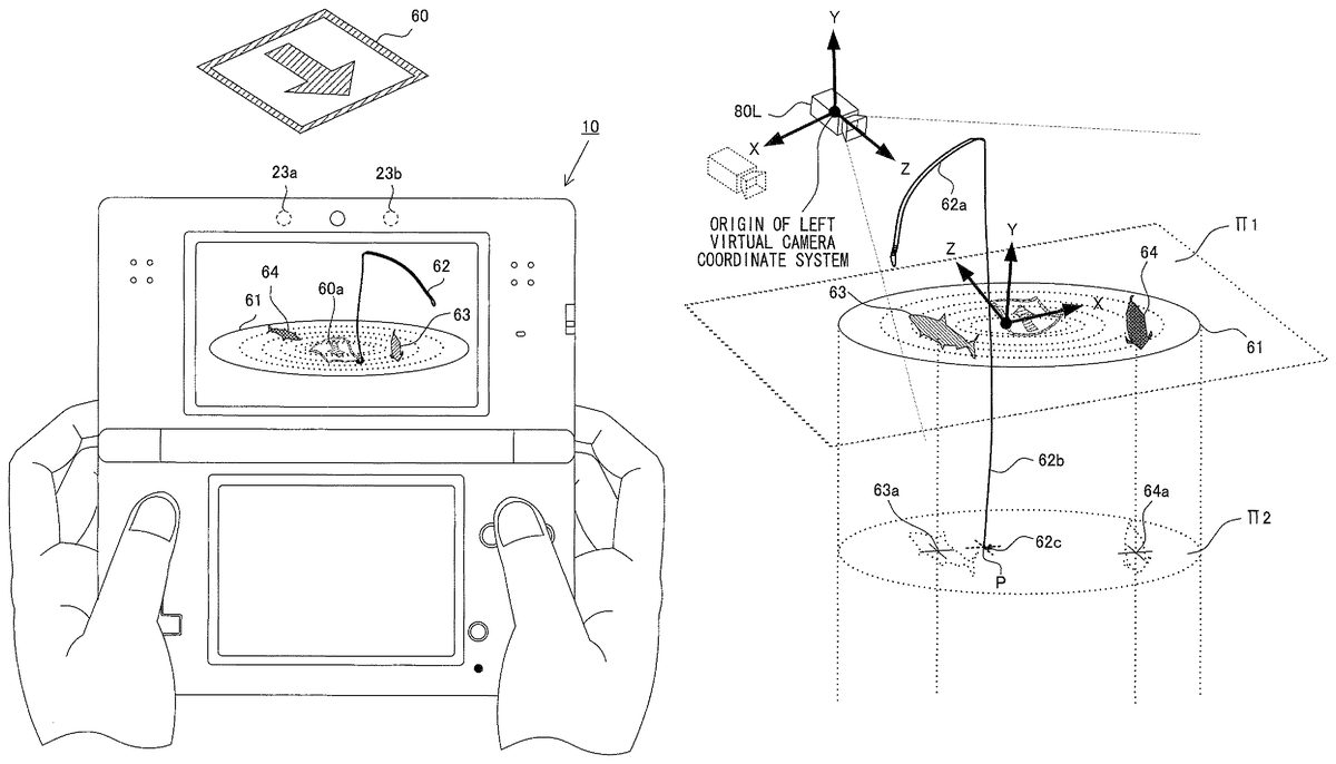
FIG. 7Ais a diagram illustrating an example of an image displayed on the upper LCD22when an image of a visual marker (hereinafter, referred to as marker)60is taken by the outer imaging section23. The marker60has, on its surface, a square pattern including an arrow like pattern. The information processing section31can determine whether or not an image (real world image) obtained from the outer imaging section23includes the marker, by performing image processing (e.g., pattern matching) on the real world image. In addition, on the basis of the position and the orientation of the recognized marker60, a marker coordinate system (a coordinate system having an origin at a predetermined point in a virtual space corresponding to the position of the marker60in the real world) is defined.
Next, on the basis of the position and the orientation of the marker60and information calculated from the position and the like, the information processing section31displays a plurality of virtual objects (e.g., a fishing rod object62) on the upper LCD22such that the virtual objects are stereoscopically visible. Here, in order to appropriately combine the real world image and an image of a virtual world (a virtual world image), which is generated during the game processing, to extend/enhance perception information received from the real environment, a real space corresponding to the real world image including the marker60and a virtual space corresponding to the virtual world image need to be appropriately superimposed on each other.
Initially, the information processing section31causes a reference point in the real space to correspond to a reference point in the virtual space on the basis of the position of the marker60located in the real space. Next, the information processing section31sets a virtual camera in the virtual space such that the virtual camera has the same position and orientation as those of the outer imaging section23that takes an image of the real space. Then, the information processing section31causes the properties (e.g., parameters such as lens distortion, focal length, and an angle of view) of the virtual camera to agree with those of the outer imaging section23as necessary. In this manner, the real space corresponding to the real world image including the marker60and the virtual space corresponding to the virtual world image are appropriately superimposed on each other.
As one of the virtual objects located in the virtual space, a virtual object61that has a certain surface area and that represents a water surface (hereinafter, referred to as water surface object61) is located substantially in parallel to and on a plane that includes the marker60(a plane π1inFIG. 7C). The water surface object61is a model representing an interface between the atmosphere and a large amount of water (e.g., a pond or sea), and serves as a virtual surface defined in the virtual space.FIG. 7Aillustrates a resultant displayed combination of the marker60(60ain the combination) included in the real world image and the virtual objects.
In the exemplified embodiment, the model for representing the water surface object61is not a complete plane but a three-dimensional model having a wavy curved surface for representing a surface wave (a mechanical wave traveling along the interface between different media). The curved surface may deform at predetermined time intervals in accordance with a progress of a game.
The surface of the model that defines the water surface object61serves as a virtual surface in the virtual space, and the virtual surface can separate the virtual space into some subspaces. For example, in the present embodiment, the surface of the three-dimensional model for the water surface object61or a main surface of the water surface object61(a plane obtained by performing average approximation of recesses and projections of the model; e.g., the above plane π1) can be defined as a virtual surface that separates the virtual space into a space “on the water” and a space “in the water”. Here, when the main surface is assumed to be extended to infinity, the virtual space is separated into two spaces by the main surface. Of the two virtual spaces obtained by the separation, a space where the virtual camera is present can be defined as the space “on the water”, and the other space can be defined as the space “in the water”. The main surface of the water surface object61is actually defined as a region having a certain surface area, and thus the game processing is performed on the assumption of a limitation by the region.
It should be noted that a mode in which the virtual surface shown here is defined is intended to be illustrative, and the virtual surface in the present invention should not be limited to this example. In addition, the water surface object61may not be necessarily located in parallel to or on the plane including the marker60, and it suffices that the water surface object61is located at such a position that a representation that is appropriate for a progress of the game can be ensured.
A virtual object62, which represents a fishing rod having a fishing hook and a fishing line (hereinafter, referred to as fishing rod object62), is located in the space “on the water” so as to be closer to the virtual camera than the water surface object61. The fishing rod object62serves as a player object that is controllable by a user (player). The user moves the holding game apparatus10relative to the marker60, the position of the virtual camera is updated in accordance with the movement, and the displayed positions of the virtual objects are also updated. The fishing rod object62is updated so as to be located in front of the virtual camera in the virtual space. Thus, the user can receive a feeling as if the holding game apparatus10is connected to the fishing rod object62in the virtual space. The fishing rod object62includes a portion62arepresenting a fishing rod body (hereinafter, referred to as fishing rod body62a), a portion62bcorresponding to the fishing line (hereinafter, referred to as fishing line portion62b), and a portion62ccorresponding to the fishing hook (hereinafter, referred to as fishing hook portion62c) (seeFIG. 7E).
By the user performing an operation including movement of the game apparatus10relative to the marker60, the fishing hook portion62cof the fishing rod object62can be cast into a region under the water surface object61(that is, the space “in the water”). By so doing, the game provided by the game apparatus10progresses.
In the fishing game, the user casts the fishing hook portion62c, aiming at fish indications projected on the water surface object61(indicated by reference characters63and64inFIG. 7A). The fish indications are a part of a representation image for suggesting that objects representing fish (hereinafter, referred to as fish objects) are present in the space “in the water” (one subspace in the virtual space). Meanwhile, the fishing rod object62, which is controllable by the user, is located in the space “on the water” (a subspace, in the virtual space, which is different from the space “in the water”).
In other words, during the progress of the game, the user controls the fishing rod object62by performing an operation of moving the game apparatus10relative to the marker60, thereby establishing a certain correlation of the fishing rod object62with the fish objects located in the subspace different from the space in which the fishing rod object62is located.
When a certain pulling-up condition is satisfied while the game progresses, the user can pull a fish object corresponding to the fish indication, out of the water. Although the series of game processing will be described in more detail below (“processing according to a first embodiment”), a feeling felt by an angler during actual fishing can be more realistically reproduced by the present embodiment.
In other words, a feeling can be provided to the user as if the fishing rod object62is actually connected to the game apparatus10held by the user for operations and the fishing line portion62bis dropped from the fishing rod object62into the water surface object61that is spatially integrated with the real world. Thus, an immersed feeling and a reality feeling of the user can be enhanced.
Next, a similar embodiment according to the present invention will be described.
FIG. 7Bis a diagram illustrating another example of the image displayed on the screen of the upper LCD22when an image of the marker60is taken by the outer imaging section23.FIG. 7Billustrates only the screen of the upper LCD22. Similarly toFIG. 7A,FIG. 7Bis a diagram illustrating an example of an image displayed in which virtual objects such as the water surface object61are superimposed on the real world image including the marker60. The virtual objects located here are different from the virtual objects inFIG. 7A.
In this exemplified embodiment, a player object that is controllable by the user is a fishing rod object62′. The fishing rod object62′ has a bomb portion62dinstead of the fishing hook portion62cin the fishing rod object62shown inFIG. 7A. Meanwhile, an object65that moves while changing its position relative to the water surface object61defining the virtual surface (corresponding to the water surface) and that represents a dragon (hereinafter, referred to as dragon object65), is provided as a non-player object.
The dragon object65has a portion65athat projects upward from the upper surface of the water surface object61corresponding to the water surface (a portion located in the space “on the water”) and a portion65b(not shown in the drawing) that is located under the upper surface (a portion located in the space “in the water”). Along with the progress of the game, the information processing section31changes a ratio of the portion65aand the portion65bof the dragon object65. In other words, the dragon object65is controlled such that the dragon object65moves along the water surface displayed on the upper LCD22and also along the y axis of the marker coordinate system.
When the dragon object65is in a state of having the portion65aprojecting upward from the upper surface of the water surface object61corresponding to the water surface, the user can attack the dragon object65. In other words, unless coming out into the space “on the water” through the virtual surface, the dragon object65does not become a virtual object that can be attacked by the user.
Specifically, when the dragon object65has a portion exposed on the water surface, the user drops the bomb portion62dat an end of the fishing rod object62′ by separating the bomb portion62dtherefrom (may drop the bomb portion62dby extending the fishing line portion62binstead of separating the bomb portion62d). Then, the information processing section31determines whether or not the dropped bomb portion62dhas collided with the portion65aof the dragon object65(it suffices to use an evaluation by a general determination of collision between three-dimensional objects). As a result, when the number of times of collision or the like satisfies a defined condition, the information processing section31displays, on the upper LCD22, a presentation that the dragon object65disappears.
By the user moving the game apparatus10, the position and the orientation of the marker60displayed on the screen of the upper LCD22change, and the positions and the orientations of the displayed virtual objects also change.
The series of game processing according to this embodiment will be described in more detail below (“processing according to a second embodiment”).
Hereinafter, the game processing performed in the game apparatus10on the basis of the game program will be described in more detail with reference toFIGS. 7A to 13.
(Memory Map)
Initially, main data that is stored in the main memory32during execution of the game program will be described.FIG. 8is a diagram illustrating the memory map of the main memory32of the game apparatus10. As shown inFIG. 8, the game program70, a left real world image71L, a right real world image71R, a left view matrix72L, a right view matrix72R, virtual object information73, various variables74, and the like are stored in the main memory32.
The game program70is a program for causing the information processing section31to performs the game processing.
The left real world image71L is an image taken by the outer imaging section (left)23a.
The right real world image71R is an image taken by the outer imaging section (right)23b.
The left view matrix72L is used when rendering a virtual object that is viewed from a left virtual camera80L, and is a coordinate transformation matrix for transforming a coordinate represented in the marker coordinate system into a coordinate represented in a left virtual camera coordinate system.
The right view matrix72R is used when rendering a virtual object that is viewed from a right virtual camera80R, and is a coordinate transformation matrix for transforming a coordinate represented in the marker coordinate system into a coordinate represented in a right virtual camera coordinate system.
The virtual object information73is information on virtual objects and includes model information representing the shapes and patterns of the virtual objects, current positions of the virtual objects in the virtual space, and the like.
The various variables74are used when the game program70is executed.
When the game apparatus10is powered on, the information processing section31(the CPU311) of the game apparatus10executes a boot program stored in a ROM (not shown), thereby initializing each unit such as the main memory32. Next, the game program stored in the internal data storage memory35is loaded into the main memory32, and execution of the game program is started by the CPU311of the information processing section31.
Hereinafter, flows of the processing performed on the basis of the game program will be described with reference to flowcharts inFIGS. 9A and 9B. InFIGS. 9A and 9B, “step” is abbreviated as “S”. It should be noted that the flowcharts inFIGS. 9A and 9Bare merely examples. Therefore, the order of each process step may be changed as long as the same result is obtained. In addition, the values of the variables and thresholds used at determination steps are also merely examples, and other values may be used as necessary. Moreover, in the present embodiment, the CPU311performs processes at all steps in the flowcharts inFIGS. 9A and 9B. However, a processor or a dedicated circuit other than the CPU311may perform processes at some of the steps in the flowcharts inFIGS. 9A and 9B.
(Processing According to First Embodiment: Fishing Game)
FIG. 9Ais a flowchart illustrating a flow of the game processing performed by the CPU311on the basis of the game program70. Specifically,FIG. 9Aillustrates exemplified processing according to a game that incorporates elements of fishing in the real world into the progress of the game. Hereinafter, details of the game processing will be described.
At step101inFIG. 9A, the CPU311sets the water surface object61on the basis of information of the position and the like of the marker60that is recognized on the basis of an image taken by the outer imaging section23of the game apparatus10.
In the present embodiment, the CPU311causes coordinates in the virtual space to correspond to absolute coordinates in the real space (e.g., coordinates in the marker coordinate system) on the basis of the marker60. The CPU311sets a predetermined position in the marker60recognized by pattern matching or the like, as the origin of the marker coordinate system (FIG. 7C).FIG. 7Cis a diagram schematically illustrating a relative position of the virtual camera (the left virtual camera80L is indicated by a solid line and the right virtual camera80R is indicated by a dotted line in this drawing) and the marker60. The process of recognizing the marker, which is performed here, is the same in principle as a part of a process concerning marker recognition and update at subsequent step102.
Next, the CPU311sets the virtual camera such that the virtual camera has the same position and orientation with respect to the marker60, which is a reference point, as those of the outer imaging section23that takes an image of the real space. Then, the CPU311causes the properties (e.g., parameters such as lens distortion, focal length, and an angle of view) of the virtual camera to agree with those of the outer imaging section23as necessary. In this manner, the real space corresponding to the real world image including the marker60and the virtual space corresponding to the virtual world image are appropriately superimposed on each other. The setting of the virtual camera, which is performed here, is the same in principle as a part of a process of updating the position of the virtual camera at subsequent step103.
Next, the CPU311locates the water surface object61in the virtual space such that the water surface object61is parallel to the plane π1including the marker60(seeFIG. 7D).FIG. 7Dillustrates an example of the water surface object61located in the virtual space. Here, the CPU311performs mapping of an image taken by the outer imaging section23to the surface of the three-dimensional model (e.g., a model of a polygon) indicating the water surface object61. In addition, the CPU311performs mapping of a taken image of the real world including the marker60to a representation of the three-dimensional model for the water surface object61.
As described above, after the virtual camera in the virtual space is set at a position corresponding to the outer imaging section23(real camera) with respect to the marker60, the CPU311performs mapping of the above taken image to the three-dimensional model (polygon) indicating the water surface object61. Thus, it is possible to generate a superimposed image that is viewed by the user as if the water surface appears in the real world. Incidentally, by the mapping being performed, the taken image follows the shape of the three-dimensional model for the water surface object61and is viewed such that a part thereof is deformed (e.g., the marker60becomes a form indicated by60ainFIG. 7D).
At step102, the CPU311performs a recognition process of the marker60on the basis of the image obtained by the outer imaging section23, and updates the coordinates in the marker coordinate system.
At step103, the CPU311updates the position and the orientation of the virtual camera on the basis of the updated coordinates calculated at step102. Although described below, the update of the position and the orientation of the virtual camera is performed by the CPU311calculating a view matrix (a matrix in which the position and the orientation of the virtual camera that are calculated on the basis of the position and the orientation of the marker in the real world image are reflected). In addition, similarly to step101, the CPU311can cause the properties (e.g., parameters such as lens distortion, focal length, and an angle of view) of the virtual camera to agree with those of the outer imaging section23as necessary.
Hereinafter, details of the series of processes at steps101to103will be described. First, the marker recognition process performed at steps101and102will be described. It should be noted that the marker recognition process described here is described on the assumption that the game apparatus10provides a stereoscopically visible image to the user. When stereoscopic viewing is not required, one skilled in the art can specifically understand a marker recognition process performed in the case where stereoscopic viewing is not performed, from the following description.
As described above, in the upper housing21, there is a certain interval (e.g., 3.5 cm) between the outer imaging section (left)23aand the outer imaging section (right)23b. Thus, when images of the marker60are simultaneously taken by the outer imaging section (left)23aand the outer imaging section (right)23b, the position and the orientation of the marker60in a left real world image taken by the outer imaging section (left)23aare different from the position and the orientation of the marker60in a right real world image taken by the outer imaging section (right)23b, as shown inFIG. 10, due to the parallax. The CPU311performs the marker recognition process on at least either one of the left real world image or the right real world image.
For example, when performing the marker recognition process on the left real world image, the CPU311determines whether or not the marker60is included in the left real world image, by using pattern matching or the like. When the marker60is included in the left real world image, the CPU311calculates a left view matrix72L on the basis of the position and the orientation of the marker60in the left real world image. The left view matrix72L is a matrix in which a position and an orientation of the left virtual camera that are calculated on the basis of the position and the orientation of the marker60in the left real world image are reflected.
More precisely, as shown inFIG. 11, the left view matrix72L is a coordinate transformation matrix for transforming a coordinate represented in the marker coordinate system in the virtual space (a coordinate system having an origin at a predetermined point in the virtual space corresponding to the position of the marker60in the real world) into a coordinate represented in a left virtual camera coordinate system based on the position and the orientation of the left virtual camera80L (the virtual camera in the virtual space corresponding to the outer imaging section (left)23ain the real world) that are calculated on the basis of the position and the orientation of the marker60in the left real world image.
Further, when performing the marker recognition process on the right real world image, the CPU311determines whether or not the marker60is included in the right real world image, by using pattern matching or the like. When the marker60is included in the right real world image, the CPU311calculates a right view matrix72R on the basis of the position and the orientation of the marker60in the right real world image. The right view matrix72R is a matrix in which a position and an orientation of the right virtual camera that are calculated on the basis of the position and the orientation of the marker60in the right real world image are reflected.
More precisely, as shown inFIG. 12, the right view matrix72R is a coordinate transformation matrix for transforming a coordinate represented in the marker coordinate system in the virtual space (the coordinate system having the origin at the predetermined point in the virtual space corresponding to the position of the marker60in the real world) into a coordinate represented in a right virtual camera coordinate system based on the position and the orientation of the right virtual camera80R (the virtual camera in the virtual space corresponding to the outer imaging section (right)23bin the real world) that are calculated on the basis of the position and the orientation of the marker60in the right real world image.
When it is assumed that there are no errors in accuracy of the marker recognition and there are no errors in accuracy of mounting the outer imaging section (left)23aand the outer imaging section (right)23bto the game apparatus10, the position of the right virtual camera80R that is calculated from the marker recognition result of the right real world image is a position that is shifted from the position of the left virtual camera80L that is calculated from the marker recognition result of the left real world image, along the x axis direction of the left virtual camera coordinate system by a certain distance. In addition, the orientation of the right virtual camera80R that is calculated from the marker recognition result of the right real world image is the same as the orientation of the left virtual camera80L that is calculated from the marker recognition result of the left real world image (that is, the x axis, the y axis, the z axis of the left virtual camera coordinate system are parallel to the x axis, the y axis, the z axis of the right virtual camera coordinate system, respectively).
However, since there are in reality some errors in accuracy of the marker recognition and accuracy of mounting the outer imaging section (left)23aand the outer imaging section (right)23bto the game apparatus10, the position and the orientation that are calculated from the marker recognition result of the right real world image and the position and the orientation of the right virtual camera80R that are calculated from the marker recognition result of the left real world image do not have an ideal relation (e.g., the left virtual camera80L and the right virtual camera80R are too close to each other or too distance from each other, and the orientation of the left virtual camera80L and the orientation of the right virtual camera80R are different from each other). Thus, when virtual objects are stereoscopically displayed on the upper LCD22by using the thus-calculated positions and orientations of the left virtual camera80L and the right virtual camera80R, the virtual objects may not be successfully stereoscopically viewed. Therefore, in the present embodiment, as an example, as shown inFIG. 13, the position and the orientation of the right virtual camera80R are set on the basis of the position and the orientation of the left virtual camera80L that are calculated from the marker recognition result of the left real world image.
At step104, the CPU311locates the fishing rod object62at a predetermined position in the virtual space. The fishing rod object62includes the fishing rod body62a, the fishing line portion62b, and the fishing hook portion62c. The fishing rod body62aof the fishing rod object62is located, for example, on the near side of the water surface object61when viewed from the user operating the game apparatus10, as shown inFIG. 7A. By the CPU311locating the fishing rod object62on the upper LCD22and at a position closer to the virtual camera (that is, the viewpoint of the user) than the water surface object61, a feeling can be provided to the user as if the user holds a fishing rod and casts a fishing hook into the water spreading in front of the user, for example. The fishing rod object62is controllable by the user in the game processing. By operating the game apparatus10, the user can extend the fishing line in the virtual space, cast the fishing hook portion62cinto a region indicated by the water surface object61, and locate the fishing hook portion62cin the virtual space in the water. Thus, at this step, the CPU311updates the position of the fishing hook portion62cto a position corresponding to an operation performed by the user on the game apparatus10.
At step105, the CPU311determines whether or not it is in a state where a fish object is caught on the cast-in fishing hook portion62cof the fishing rod object62(a “state where a fish (object) is caught on the fishing hook portion”). The “state where the fish object is caught on the fishing hook portion” is a state where the fish holds a fishing hook in its mouth during fishing performed in the real environment, and is an internal state that represents a state before the fish is pulled out of the water (pulled up) and that is defined for the game processing. In an initial state or when no fish object is caught on the fishing hook portion62cin the progress of the game processing (No at step105), the CPU311performs a process at subsequent step106. On the other hand, when the determination at step105is performed after the CPU311performs setting of a “state of being caught on the fishing hook portion” at subsequent step109(Yes at step105), the CPU311subsequently performs a process at step112.
At step106, the CPU311determines whether or not the fishing hook portion62cof the fishing rod object62is located under the water surface object61that is defined on the basis of the position information of the marker60and the like. The CPU311performs the determination by obtaining the coordinate of each located virtual object (e.g., the y coordinate of each object) in a predetermined coordinate system (e.g., the marker coordinate system) and comparing these coordinates. When it is determined that the fishing hook portion62cis located under the water surface (that is, the virtual surface defined on the basis of the water surface object61) (that is, in the space “in the water”), the CPU311proceeds to a process at step107.
At step107, the CPU311determines whether or not it is in a state where a fish object (a virtual object corresponding to a fish indication63or64) is nibbling the fishing hook portion62c. Here, the state where “the fish object is nibbling the fishing hook portion” is a state where it is possible to shift to a determination process of a fish pulling-up (landing) condition in a subsequent process, and is an internal state where an action of a targeted fish trying to bite a fishing hook during actual fishing is represented in the game processing.
Specifically, when the distance between the fishing hook portion62cthat has been cast under the water surface and the fish object that is a pulled-up candidate falls within a predetermined range, the CPU311determines that it is in the state where it is possible to perform the determination of the pulling-up condition (that is, the state where the fish object is nibbling the fishing hook portion) (Yes at step107). While the distance between the fishing hook portion62cand the fish object that is the pulled-up candidate falls within the predetermined range, the CPU311displays an image corresponding to a scene in which the fish indication corresponding to the fish object is nibbling, at regular time intervals, the fishing hook portion62cdisplayed on the upper LCD22(through a rendering process at step115).
It should be noted that the CPU311can set a condition for cancelling the state where “the fish object is nibbling the fishing hook portion”, during this processing. In other words, even when the distance between the fishing hook portion62cand the fish object falls within the predetermined range at a certain time point, if the “pulling-up condition” described below is not satisfied before a predetermined time period elapses, the CPU311can compulsorily cancel the internal state in the game processing as the “state where the fish object is nibbling the fishing hook portion”. When the compulsory cancellation is completed, it is not determined at step107that it is in the “state where the fish object is nibbling the fishing hook portion” (No at step107), and a representation in which the fish is going away is performed to the user in the rendering process at subsequent step115. Thus, even when the state where “the fish object is nibbling the fishing hook portion” is established in the game processing, if the pulling-up condition cannot be satisfied within the predetermined time period, the user cannot pull the fish out of the water.
In the determination of the state where “the fish object is nibbling the fishing hook portion”, the CPU311calculates the distance between the fishing hook portion62cand the fish object that is the pulled-up candidate. Here, an exemplified method of calculating such a distance will be described, but in this connection, first, a method of displaying fish indications on the water surface object61will be described.
As described above, the CPU311displays the fish indications63and64on the water surface object61as shown inFIG. 7A. The shape of the water surface object61in the virtual space is defined by the three-dimensional model (polygon). In the present embodiment, the CPU311generates a superimposed image in which a water surface looks to appear in the real world, by performing mapping of an image taken by the outer imaging section23to the polygon. Here, the CPU311can represent the fish indications63and64by blending textures for indicating these fish indications and the image of the real world of which the above mapping is performed, and displaying the resultant image on the polygon.
When the fishing hook portion62cthat has been cast in the virtual space by the user performing an operation of moving the game apparatus10is located in the y axis negative direction in the marker coordinate system with respect to the water surface object61(that is, in the case of Yes at step106), the CPU311calculates the distance between the fishing hook portion62cand each fish object generated randomly by the CPU311, or a distance regarded as being equivalent to this distance.
When the CPU311performs the distance calculation, it suffices that the CPU311obtains the position of the fishing hook portion62cand the position at which each fish object is located, and at this stage, it is not necessarily necessary to assign a model indicating a three-dimensional shape of each fish object located there.
Specifically, in the present embodiment, until performing the process at subsequent step112, the CPU311provides a representative point indicating a position in the virtual space to each fish object that is a target, and does not perform a rendering process using a three-dimensional model corresponding to each fish object. Here,FIG. 7Eis referred to.FIG. 7Eis a diagram schematically illustrating positional relations among the virtual objects and the virtual camera in the virtual space shown inFIG. 7A. In the example shown inFIG. 7E, the CPU311can randomly assign any point as a position of each fish object onto a plane π2(a plane that is parallel to the virtual surface π1and that includes a point P of the fishing hook portion62cin the virtual space). In this example, the CPU311assigns points63aand64aas the positions at which the fish objects are to be located. As a method of assigning the position, for example, the assignment can be performed by using a set of random numbers having a predetermined distribution.
The CPU311represents fish indications by blending (e.g., alpha blending) a predetermined texture (e.g., a texture having a single pure color (e.g., black) or a texture in which certain shades of color are assigned in accordance with the distance between the plane π1and the plane π2) with the taken image, which is mapped to the surface of the water surface object61, so as to correspond to the points63aand64a. By so doing, the CPU311can provide, to the user, a representation as if fish are present under the water surface defined by the water surface object61.
In the case of the example shown inFIG. 7E, the determination as to whether or not it is in the state where “the fish object is nibbling the fishing hook portion” is performed by determining that it is in this state, when the distance between the coordinate of the point P of the fishing hook portion62con the plane π2and the point63aor64afalls within a predetermined range. In this example, the method in which the plane π2is assumed is used, but the CPU311may perform the process at step107without using the plane π2. In other words, the CPU311may randomly define the positions of fish indications directly on the surface of the water surface object61located in the virtual space (or approximately on the plane π1), and then may calculate the distance between the intersection of the fishing line portion62band the surface of the water surface object61(corresponding to the point P when the plane π2is used) and a point indicating the position of each fish indication located on the water surface object61.
Meanwhile, a situation may occur where in the progress of the game provided by the game apparatus10, the user largely moves the game apparatus10and the marker60deviates from the imaging range of the outer imaging section23. However, the CPU311can lead the position and the orientation of the outer imaging section23to a state convenient for performing the marker recognition process, by limiting the positions of the fish indications displayed on the upper LCD22to a certain region.
Specifically, the CPU311can locate the fish objects such that their fish indications appear in a region between the marker60and the virtual camera in the virtual space or such that this tendency is increased.FIG. 7Fis a schematic diagram illustrating an example of a mode in which a region (a shaded portion in the drawing) where fish indications appear is limited. The position indicated by a dotted line is the position of the marker60. The direction indicated by an arrow inFIG. 7Fis a direction to the virtual camera (the outer imaging section23). When randomly locating the fish objects, it suffices that the CPU311controls this locating such that fish indications appear in the shaded region with high frequency.
Referring back toFIG. 9A, processes subsequent to step107will be described. When the state where “the fish object is nibbling the fishing hook portion” is established (Yes at step107), the CPU311performs a process of determining whether or not it is possible to pull up the fish object (step108).
At step108, the CPU311can perform a determination of the following condition. The pulling-up condition is that (A) a moving amount of the fishing rod object62in the virtual space which amount is defined on the basis of the relative position of the outer imaging section23and the marker60(an amount in which an amount by which the game apparatus10is moved relative to the marker60is reflected) reaches a predetermined value, or (B) the marker60is not detected in the marker recognition of an image taken by the outer imaging section23, even when the moving amount does not reach the predetermined value. When either condition is satisfied (Yes at step108), the CPU311determines that it is in a state where the user pulls the fish out of the water, and proceeds to subsequent step109. On the other hand, when the pulling-up condition is not satisfied (No at step108), the CPU311performs a process of updating the positions and the orientations of the objects on the basis of an input operation performed by the user on the game apparatus10and the like (step110).
The pulling-up condition (A) will be described in more detail. In accordance with the progress of the game (e.g., the state where the fish is nibbling the fishing hook), the user moves the holding game apparatus10(seeFIG. 7A) such that its position changes relative to the marker60(e.g., by a motion as if pulling up). The CPU311can use an amount by which the fishing hook portion62cmoves in the virtual space for a predetermined time period (e.g., a one-frame time) in the game processing as a result of this operation of the user (e.g., a distance by which the fishing hook portion62cmoves in the y axis positive direction in the marker coordinate system), as a moving mount that is a determination target for the pulling-up condition.
In other words, the moving amount is obtained as a result of the operation performed by the user on the game apparatus10. When the user moves the game apparatus10relative to the marker60by a predetermined action (an action of pulling up the game apparatus10for pulling the fish out of the water, with regarding the game apparatus10as a part of a fishing rod), the CPU311can assign a physical amount defining the action performed by the user in the real world, as a change amount in the virtual world (e.g., a translational moving distance of the virtual objects) on the basis of position information obtained through the marker recognition and coordinate update (step102) and the update of the position of the virtual camera (step103). For example, when the fishing hook portion62cis located in the virtual world as shown inFIG. 7Eand then it becomes a state where any fish object is caught on the fishing hook portion62c, the CPU311can use the distance Δy) from the plane π2to the fishing hook portion62cwhen the fishing hook portion62cmoves in the y axis positive direction as a result of an operation of the user, as the moving mount that is the determination target for the pulling-up condition.
Meanwhile, the pulling-up condition (B) is the case where even when this moving amount does not reach the predetermined value, the marker60is not detected in the marker recognition of an image taken by the outer imaging section23. This condition is a condition for avoiding the case where as a result of an action performed by the user holding the game apparatus10, even if the moving amount exceeds the predetermined value, the recognition of the marker60fails since the action is large.
Next, at step109, the CPU311sets the internal state in the progress of the game as the state where the fish is caught on the hook. When with this setting maintained, an end condition (see subsequent step111) such as performing an input for ending the game is not satisfied and the game processing continues, the CPU311determines at step105that it is in the “state where the fish (object) is caught on the hook (portion)” (Yes at step105), and proceeds to step112.
At step111, the CPU311determines whether or not the end condition is satisfied. The end condition can be set according to the situation of the game processing such that the end condition is satisfied when the user performs an action assigned to an input operation on the game apparatus10. For example, this action is the user pressing a predetermined button (e.g., the start button14L, or the power button14F) in the game apparatus10and selecting end of the game processing in a menu display in which an end operation of the game processing can be selected. However, this action is not limited thereto.
At step112, the CPU311locates the fish object at the tip of the hook. In the present embodiment, for example, a process of providing a specific three-dimensional model (polygon) to the fish object assumed at the position63ainFIG. 7Eis not performed in the processing prior to this step. At step112, in order that the user feels presence of the fish similarly as an angler feels when pulling a fish out of the water, the CPU311locates a three-dimensional object at the tip of the fishing hook portion62cwhen the fish object is pulled up. Then, the CPU311proceeds to next step113.
At step113, the CPU311determines whether or not it is in a state where the fish object is pulled above the water surface. At this step, the CPU311performs the same process as the moving amount calculation/evaluation process performed at step108. For example, when the moving amount of the game apparatus10in the state immediately before this step (e.g., a moving amount along the y axis of the marker coordinate system) is equal to or higher than a predetermined value, the CPU311determines that “the fish object is pulled above the water surface” (Yes at step113), and can perform a process at subsequent step114. On the other hand, when determining at step113that “the fish object is not pulled above the water surface”, the CPU311performs a process at subsequent step110.
At step114, the CPU311performs a representation indicating that the fish object is obtained. The CPU311performs a representation using the three-dimensional model located at step112.
At step115, the CPU311performs the rendering process. The CPU311displays a game image to the user in accordance with the internal state in the game processing and according to a procedure stored in a storage area of the game apparatus10.
(One Example of Effect Provided by First Embodiment)
According to such a configuration of the present embodiment, a feeling can be provide to the user as if fish and a fishing rod are present in the real space, the fishing rod is connected to the game apparatus10, and a line is dropped therefrom into a water surface. Thus, when the fishing game is played while the game apparatus10is operated, feelings such as an immersed feeling and a reality feeling can be enhanced as compared to those with a conventional game apparatus.
More specifically, in the game apparatus10of the present embodiment, with respect to the virtual surface (the water surface object61) that is set on the basis of the visual marker (marker60) for generating a superimposed image by combining a real world image and a virtual world image, the player object (the fishing rod object62) is located in the virtual space on the virtual camera side (the space on the water), while the non-player objects (the fish objects) are located in the “space in the water” that is defined so as to be adjacent to the space on the water and separated by the virtual surface from the space on the water. In such a configuration, the user participates in the game by holding the game apparatus10while viewing the above superimposed image displayed on the display device (the upper LCD22) integral to the game apparatus10, and by performing an operation of moving the outer imaging section23taking an image of the marker60, that is, the entire game apparatus10, relative to the marker60. Thus, feelings such as an immersed feeling and a reality feeling that are enhanced as compared to those with a conventional game apparatus can be provided to the user.
Further, in the game processing, the game apparatus10changes the positional relation of either of the player object or the non-player objects or both of them with respect to the virtual surface. Thus, feelings such as an immersed feeling and a reality feeling that are further enhanced can be provided to the user.
Further, as described above, the method of representing fish indications by blending a predetermined texture with a take image that is mapped to the water surface object61allows rendering a group of fish objects, assumed under the water surface, by using sequentially a three-dimensional model (polygon) to be avoided. Thus, a feeling that is obtained by an angler at a water's edge during fishing can be provided even while the load on the game processing is greatly reduced.
Meanwhile, in the conventional art, when fish indications for fish objects to which three-dimensional models located under a water surface are provided are represented by using transparent processing, in particular, when a superimposed image is generated with an image of the real world, it is difficult to achieve both more realistic rendering of a region having a large depth of water (e.g., a region corresponding to a sea or lake bottom and a region that incoming visible light does not reach) and seamlessly synthesizing virtual objects with a taken image of the real world. However, if the method used in the exemplified embodiment described above is used, it is easy to represent a water surface having a surface wave while rendering fish indications as necessary, even by using an opaque real world image that has not been subjected to transparent processing, without being restrained by the problems concerning rendering of a region having a large depth of water.
(Processing According to Second Embodiment: Dragon Shooting Game)
FIG. 9Bis a flowchart illustrating another example of the game processing performed by the CPU311on the basis of the game program70.FIG. 7Bis a diagram illustrating an example of a superimposed image that is shown during the game processing according to the present embodiment and in which virtual objects are superimposed on a taken image of the real world.
Processes at steps201to203are the same as the processes at steps101to103inFIG. 9A. In the present embodiment as well, similarly to the first embodiment, the water surface object61is set on the basis of the position of the marker60.
At step204, the CPU311locates the fishing rod object62′ at a predetermined position in the virtual space. Specifically, the fishing rod object62′ is substantially the same in configuration as the fishing rod object62but has the bomb portion62dinstead of the fishing hook portion62c(seeFIG. 7B). During the game processing, the bomb portion62dcan be separated from the other portion of the fishing rod object62′ at any position in the virtual space in accordance with an operation of the user.
At step205, the CPU311determines whether or not the number of times the dragon object65has collided with the bomb portion62dis equal to or higher than a defined number (e.g., one time, two times, or three times). The determination concerning the number of times of the collision is performed on the basis of information that is set at subsequent step209on the basis of a result of a determination of collision between the dragon object65and the bomb portion62d. When the number of times of the collision is equal to or higher than the defined number (Yes at step205), the CPU311performs a dragon disappearing representation defined at step212. On the other hand, when the number of times of the collision is less than the defined number (No at step205), the CPU311proceeds to a process at step206.
At step206, the CPU311determines whether or not the dragon object65is in a state of having the portion65aprojecting upward from the upper surface of the water surface object61corresponding to the water surface. As described above, the dragon object65is controlled such that the dragon object65moves along the water surface displayed on the upper LCD22and also along the y axis of the marker coordinate system. In the game processing, when the dragon object65is in the state of having the portion65a(seeFIG. 7B) projecting upward from the upper surface of the water surface object61corresponding to the water surface, the user can attack the dragon object65with the bomb portion62d.
At step207, the CPU311determines whether or not the user has separated the bomb portion62dfrom the fishing rod object62′ and has dropped the bomb portion62dtoward the water surface by performing an operation of moving the game apparatus10relative to the marker60. When the bomb portion62dhas been separated (Yes at step208), the CPU311performs a process defined at step208. On the other hand, when the bomb portion62dhas not been separated (No at step207), there is no need to consider the correlation between the dragon object65and the bomb portion65d, and thus the CPU311proceeds to a process concerning update of the positions and the orientations of the virtual objects, defined at step210.
At step208, the CPU311performs a determination of collision between virtual objects, that is, the dragon object65and the bomb portion62d. When it is determined that the dragon object65and the bomb portion62dhave collided with each other (Yes at step208), the CPU311performs a process defined at step209. On the other hand, when it is determined that the dragon object65and the bomb portion62dhave not collided with each other (No at step208), the CPU311proceeds to the process concerning update of the positions and the orientations of the virtual objects, defined at step210.
At step209, the CPU311sets the internal state in the progress of the game as a collision state. The collision state includes information such as the number of times of collision, and in the subsequent game processing, a representation or the like based on the information are performed.
At step210, the CPU311updates the position and the orientation of each virtual object so as to reflect an operation performed by the user on the game apparatus10, as described above.
At step211, the CPU311determines whether or not an end condition is satisfied. This is the same process as that at step111in the flow shown inFIG. 9A.
At step212, as a result of determining at step205that the number of times of the collision is equal to or higher than the defined number, the CPU311performs a representation in which the dragon disappears in the progress of the game and which indicates that a mission provided in the game is cleared.
At step213, in accordance with the internal state and the determination results in the game processing, the CPU311performs a rendering process of sequentially rendering a superimposed image in which an image including the virtual objects is superimposed on a taken image of the real world.
(One Example of Effect Provided by Second Embodiment)
The game apparatus10changes the positional relation of either of the player object or the non-player object or both of them with respect to the virtual surface. Thus, feelings such as an immersed feeling and a reality feeling that are further enhanced can be provided to the user.
(Modifications)
In the embodiments described above, the position and the orientation of the marker60included in the real world image are recognized, and the virtual objects are synthesized with the real world image in accordance with the recognition result. However, in another embodiment, instead of the marker60, the position and/or the orientation of any recognition target may be recognized, and the virtual objects may be synthesized with the real world image in accordance with the recognition result. One example of the recognition target is a human face.
In the embodiments described above, the stereoscopic image is displayed on the upper LCD22on the basis of the real world image taken in real time by the outer imaging section23. However, in another embodiment, a stereoscopic image may be displayed on the upper LCD22on the basis of data of a moving image previously taken by the outer imaging section23, an external stereo camera, or the like.
In the embodiments described above, the outer imaging section23is previously mounted to the game apparatus10. However, in another embodiment, an external camera detachable from the game apparatus10may be used.
In the embodiments described above, the upper LCD22is previously mounted to the game apparatus10. However, in another embodiment, an external stereoscopic display detachable from the game apparatus10may be used.
In the embodiments described above, the virtual objects are synthesized with the real world image and displayed by using the game apparatus10. However, in another embodiment, the virtual objects may be synthesized with the real world image and displayed by using any information processing apparatus or information processing system (e.g., a PDA (Personal Digital Assistant), a mobile phone, a personal computer, or a camera).
In the embodiments described above, the game processing is executed by using only one apparatus (the game apparatus10). However, in another embodiment, a plurality of information processing apparatuses, included in an image display system, that can communicate with each other may share the execution of the game processing.
Recently, as a general trend, operating systems of typical computers are composed of various separate parts, called modules or functions; and offer a number of services via the separate parts. Further, in a commonly employed scheme, an application program calls such modules, if needed, for providing its service. In addition, software for general platforms is not always accompanied with such modules as a package; that is, it can be distributed without modules which are provided commonly in such platforms. Thus, software would be provided, which have been distributed without some modules or functions during the course of distribution thereof; and can offer a service which falls into the scope of the present invention, in connection with modules implemented in a computer executing the software. Such software can be distributed in various ways such as via computer network, in form of a storage medium having such software stored therein, and the like. Therefore, software or program deliberately provided in the above-mentioned manner, should be contemplated to fall into the scope of the above game program.
In the embodiments described above, a video see-through technique has been described in which a camera image taken by the outer imaging section23and virtual objects (e.g., the water surface object61) are superimposed on each other and displayed on the upper LCD22. However, the present invention is not limited thereto. For example, an optical see-through technique may be implemented. In the optical see-through technique, a display device that includes at least an imaging section and that is worn at the head of the user (hereinafter, referred to as head mounted display) is used. The user wearing the head mounted display can view the real space through a display section (screen) located at a position corresponding to a lens part of eye glasses. The display section is formed from a material that allows the user to view the real space therethrough. In addition, the display section allows an image of a virtual object generated by a computer to be displayed thereon. Further, the display section includes a liquid crystal display device or the like, and is configured to display an image of a virtual object generated by a computer, on the liquid crystal display device or the like and guide light from the liquid crystal display device to the user's retina (by reflecting the light by a half mirror or the like). Thus, the user can view an image in which the image of the virtual object is optically superimposed on the real space. A camera included in the head mounted display is used for detecting a marker located in the real space. Further, as another optical see-through technique, there is a technique in which a half mirror is not used and a transmissive liquid crystal display device is laminated on the display section. The present invention may use this technique. In this case, when an image of a virtual object is displayed on the transmissive liquid crystal display device, the image of the virtual object displayed on the transmissive liquid crystal display device is superimposed on the real space viewed through the display section, and the image of the virtual object and the real space are viewed by the user.
While the invention has been described in detail, the foregoing description is in all aspects illustrative and not restrictive. It is understood that numerous other modifications and variations can be devised without departing from the scope of the invention. It should be understood that the scope of the present invention is interpreted only by the scope of the claims. It is also understood that, from the description of specific embodiments of the present invention, the one skilled in the art can easily implement the present invention in the equivalent range based on the description of the present invention and on the common technological knowledge. Further, it should be understood that terms used in the present specification have meanings generally used in the art concerned unless otherwise specified. Therefore, unless otherwise defined, all the jargon and technical terms have the same meanings as those generally understood by one skilled in the art of the present invention. In the event of any conflict, the present specification (including meanings defined herein) has priority.
Claims
- A non-transitory computer-readable storage medium having a game program stored therein, the game program causing a computer of a game apparatus, which is connected to an imaging device and a display device that allows a real space to be viewed on a screen thereof, to perform functionality comprising: obtaining a taken image obtained by the imaging device taking an image of the real space;detecting a specific object from the obtained taken image;calculating an imaging device position of the imaging device with respect to the detected specific object;setting a virtual camera in a virtual space on the basis of the imaging device position;setting, on the basis of the imaging device position, a virtual surface in the virtual space and defining subspaces extending at least along a depth direction relative to the virtual surface in the virtual space;providing, on the basis of a virtual camera position of the virtual camera, a first virtual object in a first subspace of the virtual space that is defined by the virtual surface;generating a virtual object image by taking, by the virtual camera, the virtual space including the first virtual object;displaying the virtual object image on the display device such that the virtual object image is superimposed on the real space on the screen and viewed by a user;providing a second virtual object different from the first virtual object, in the virtual space in accordance with a progress of a game;and controlling the progress of the game in accordance with changing a positional relation of either one of the first virtual object or the second virtual object or both of them with respect to the virtual surface.
- The non-transitory computer-readable storage medium according to claim 1 , wherein the game program further causes the computer to execute functionality comprising performing a determination of a condition concerning a correlation between the first virtual object and the second virtual object for subsequent game processing.
- The non-transitory computer-readable storage medium according to claim 1 , wherein when at least a part of the first virtual object that is present in the first subspace is moved through the virtual surface into a second subspace that is farther away from the virtual camera than the virtual surface, a determination of a condition concerning a correlation between the first virtual object and the second virtual object for subsequent game processing is performed.
- The non-transitory computer-readable storage medium according to claim 3 , wherein the condition concerning the correlation is that a positional relation of the first virtual object and the second virtual object satisfies a predetermined condition.
- The non-transitory computer-readable storage medium according to claim 3 , wherein the condition concerning the correlation is that a moving amount of the first virtual object that is defined on the basis of the obtained imaging device position reaches a predetermined value.
- The non-transitory computer-readable storage medium according to claim 3 , wherein the condition concerning the correlation is that even when a moving amount of the first virtual object that is defined on the basis of the obtained imaging device position does not reach a predetermined value, the specific object from the taken image is not detected.
- A game apparatus having at least one processor and configured to be connected to an imaging device and a display device that allows a real space to be viewed on a screen thereof, the game apparatus configured to: obtain a taken image obtained by the imaging device taking an image of the real space;detect a specific object from the obtained taken image;calculate an imaging device position of the imaging device with respect to the specific object on the basis of a detection result of the specific object;set a virtual camera in a virtual space on the basis of the imaging device position;set, on the basis of the imaging device position, a virtual surface in the virtual space and define subspaces extending at least along a depth direction relative to the virtual surface in the virtual space;provide, on the basis of a position of the virtual camera, a first virtual object in a first subspace of the virtual space that is defined by the virtual surface;generate a virtual object image by taking, by the virtual camera, the virtual space including the first virtual object;display the virtual object image on the display device such that the virtual object image is superimposed on the real space on the screen and viewed by a user;provide a second virtual object different from the first virtual object, in the virtual space in accordance with a progress of a game;and control the progress of the game in accordance with changing a positional relation of either one of the first virtual object or the second virtual object or both of them with respect to the virtual surface.
- A game system comprising: an imaging device;a display device configured to allow a real space to be viewed on a screen of the display device;and a game apparatus operatively coupled to the imaging device and the display device and configured to: obtain a taken image obtained by the imaging device taking an image of the real space, detect a specific object from the obtained taken image, calculate an imaging device position of the imaging device with respect to the specific object on the basis of a detection result of the specific object, set a virtual camera in a virtual space on the basis of the imaging device position, set, on the basis of the imaging device position, a virtual surface in the virtual space and define subspaces extending at least along a depth direction relative to the virtual surface in the virtual space, provide, on the basis of a position of the virtual camera, a first virtual object in a first subspace of the virtual space that is defined by the virtual surface, generate a virtual object image by taking, by the virtual camera, the virtual space including the first virtual object, display the virtual object image on the display device such that the virtual object image is superimposed on the real space on the screen and viewed by a user, provide a second virtual object different from the first virtual object, in the virtual space in accordance with a progress of a game, and control the progress of the game in accordance with changing a positional relation of either one of the first virtual object or the second virtual object or both of them with respect to the virtual surface.
- A method for performing game processing in a game system having one or more processors, the method comprising: obtaining a taken image obtained by taking an image of a real space the imaging device by an imaging device connected to the game system;detecting a specific object from the obtained taken image;calculating, via the one or more processors, an imaging device position of the imaging device with respect to the detected specific object;setting a virtual camera in a virtual space on the basis of the imaging device position;setting, on the basis of the imaging device position, a virtual surface in the virtual space and defining subspaces extending at least along a depth direction relative to the virtual surface in the virtual space;providing, on the basis of a position of the virtual camera, a first virtual object in a first subspace of the virtual space that is defined by the virtual surface;generating a virtual object image by taking, by the virtual camera, the virtual space including the first virtual object;displaying the virtual object image on a display device connected to the game system, such that the virtual object image is superimposed on the real space on a screen of the display device and viewed by a user;providing a second virtual object different from the first virtual object, in the virtual space in accordance with a progress of a game;and controlling the progress of the game in accordance with changing a positional relation of either one of the first virtual object or the second virtual object or both of them with respect to the virtual surface.
- A game system connected to an imaging device and a display device that allows a real space to be viewed on a screen thereof, the game system comprising: a marker having a feature of serving as a specific object;and a processing system having at least one processor, the processing system configured to: obtain a taken image obtained by the imaging device taking an image of the real space;detect the specific object from the obtained taken image;calculate an imaging device position of the imaging device with respect to the specific object on the basis of a detection result of the specific object;set a virtual camera in a virtual space on the basis of the imaging device position;set, on the basis of the imaging device position, a virtual surface in the virtual space and define subspaces extending at least along a depth direction relative to the virtual surface in the virtual space;provide, on the basis of a position of the virtual camera, a first virtual object in a first subspace of the virtual space that is defined by the virtual surface;generate a virtual object image by taking, by the virtual camera, the virtual space including the first virtual object;display the virtual object image on the display device such that the virtual object image is superimposed on the real space on the screen and viewed by a user;provide a second virtual object different from the first virtual object, in the virtual space in accordance with a progress of a game;and control the progress of the game in accordance with changing a positional relation of either one of the first virtual object or the second virtual object or both of them with respect to the virtual surface.
- The non-transitory computer-readable storage medium according to claim 1 , wherein the real space exists in a real world environment and the virtual space exists in a virtual gaming environment.
- The non-transitory computer-readable storage medium according to claim 1 , wherein the virtual surface represents a three-dimensional virtual surface extending along a first axis, a second axis, and a third axis in the virtual space.
- The non-transitory computer-readable storage medium according to claim 12 , wherein the first axis extends along a longitudinal direction, the second axis extends along a latitudinal direction, and the third axis extends along the depth direction in the virtual space, and the subspaces are defined in the third axis extending along the depth direction in the virtual space.
Disclaimer: Data collected from the USPTO and may be malformed, incomplete, and/or otherwise inaccurate.