U.S. Pat. No. 9,056,255
GAME CONTROLLER, GAME MACHINE, AND GAME SYSTEM USING THE GAME CONTROLLER
AssigneeTOSHIBA SAMSUNG STORAGE TECHNOLOGY KOREA CORPORATION
Issue DateJuly 15, 2011
Illustrative Figure
Abstract
A game controller, a game machine, and a game system including the game system. The game controller is a device for manipulating a game program, and at least a portion of a body portion of the game controller is deformable to have forms that are adapted to contents of a game. Accordingly, a physical sensation when a user plays a game may be improved.
Description
DETAILED DESCRIPTION OF THE INVENTION The present invention will now be described more fully with reference to the accompanying drawings, in which exemplary embodiments of the invention are shown. The invention may, however, be embodied in many different forms and should not be construed as being limited to the embodiments set forth herein; rather, these embodiments are provided so that this disclosure will be thorough and complete, and will fully convey the concept of the invention to those of ordinary skill in the art. Like reference numerals in the drawings denote like elements, and thus sizes of elements may be exaggerated in the drawings for clarity and convenience of description. FIG. 1illustrates a game controller100according to an embodiment of the present invention. Referring toFIG. 1, the game controller100includes a first body portion110and a second body portion120. The first body portion110and the second body portion120may be regarded as frames or a housing of the game controller100. The first body portion110has a flexible structure that is deformable to have a plurality of various forms. That is, the first body portion100may be deformed to have various forms such as a straight line, a straight line having two portions that are bent in different directions, or a circle having a grip, may also be returned to its original form, and may be maintained in the deformed form. The second body portion120may have a bar shape and may include a wireless or wired input/output module through which a signal may be transmitted to or received from a computer in which a game program is executed, that is, a main body of a game machine. Alternatively, a computer in which game programs are executed may be included in the second body portion120, or the game controller100may itself be a game machine in which game programs are ...
DETAILED DESCRIPTION OF THE INVENTION
The present invention will now be described more fully with reference to the accompanying drawings, in which exemplary embodiments of the invention are shown. The invention may, however, be embodied in many different forms and should not be construed as being limited to the embodiments set forth herein; rather, these embodiments are provided so that this disclosure will be thorough and complete, and will fully convey the concept of the invention to those of ordinary skill in the art. Like reference numerals in the drawings denote like elements, and thus sizes of elements may be exaggerated in the drawings for clarity and convenience of description.
FIG. 1illustrates a game controller100according to an embodiment of the present invention.
Referring toFIG. 1, the game controller100includes a first body portion110and a second body portion120. The first body portion110and the second body portion120may be regarded as frames or a housing of the game controller100.
The first body portion110has a flexible structure that is deformable to have a plurality of various forms. That is, the first body portion100may be deformed to have various forms such as a straight line, a straight line having two portions that are bent in different directions, or a circle having a grip, may also be returned to its original form, and may be maintained in the deformed form.
The second body portion120may have a bar shape and may include a wireless or wired input/output module through which a signal may be transmitted to or received from a computer in which a game program is executed, that is, a main body of a game machine. Alternatively, a computer in which game programs are executed may be included in the second body portion120, or the game controller100may itself be a game machine in which game programs are executed independently. According to circumstances, the second body portion120may be omitted. When the second body portion120is omitted, a computer for executing game programs and a wireless or wired input/output module for transmitting/receiving a signal may be installed in the first body portion110or a computer for executing game programs may be installed in the first body portion110.
An example of the flexible structure of the first body portion110is illustrated inFIG. 2. Referring toFIG. 2, a plurality of frames, first through third frames111,112, and113that are serially arranged constitute a multi-joint structure in which they are rotatably coupled to one another. First and second fixing links114and115and first through third moving links116,117, and118are formed along two lines of a central line that passes through rotational axes R1and R2of the frames111,112, and113. A first end of the first fixing link114and a first end of the second moving link116are rotatably fixed to the first frame111at a front end. Also, in the second frame112, long grooves112aand112bthat are extended in a lengthwise direction of the second frame112are formed on two sides of the central line passing through the rotational axes R1and R2. Also, long grooves113aand113bthat are extended in a lengthwise direction of the third frame113are formed on two sides of the central line passing through the rotational axes R1and R2in the third frame113. A pin119athat rotatably couples a second end of the first fixing link114and a first end of the second fixing link115is inserted into the long groove112aso as to move linearly in a lengthwise direction of the long groove112a. Also, a pin119bthat rotatably couples a second end of the second fixing link115to the third frame113is inserted into the long groove113aso as to move linearly in a lengthwise direction of the long groove113a. Also, a pin119cthat rotatably couples a second end of the first moving link116to a first end of the second moving link117is inserted into the long groove112bso as to move linearly in a lengthwise direction of the long groove112b. Also, a pin119dthat rotatably couples a second end of the second fixing link115to a first end of the third moving link118is inserted into the long groove113bso as to move linearly in a lengthwise direction of the long groove113b. The third moving link118may be selectively fixed using a separate fixing unit (e.g., a screw, a pin, etc.).
When moving the third moving link118in the first body portion110having the above-described structure, a portion of each of the first through third frames111through113receives a force around the rotational axes R1and R2, and the first through third frames111through113will bend. On the other hand, when the third moving link118is fixed, the bent shape of the first through third frames111through113may be fixed. WhileFIG. 2illustrates a multi-joint structure formed of three frames (the first through third frames111through113), alternatively, a plurality of second frames112may be serially connected. The first body portion110having a multi-joint structure as described above may be deformed to have a shape according to the contents of a game as will be described later, and thus body sensation may be significantly improved when playing games.
The flexible structure of the first body portion110ofFIG. 2is an example and the present invention is not limited thereto. For example, a multi-joint device, in which a fixing element is formed at each joint, or other well-known, fixable structures may be used as the flexible structure of the first body portion110. For example, when the first body portion110has a multi-joint structure in which a fixing element is formed at each joint and each joint may be independently rotated, the first body portion110may have more various shapes.
FIGS. 3 and 4illustrate examples of deformable shapes of the first body portion110. The first body portion110may have not only a straight linear shape as illustrated inFIG. 1but also a circle shape like a steering wheel as illustrated inFIG. 3or a straight line shape having two portions that are bent in different directions as illustrated inFIG. 4.
For example, if a game to be played requires a straight-line instrument, such as fencing or golf, the game controller100may have a straight linear shape as illustrated inFIG. 1to manipulate the game. Alternatively, if a game to be played requires a circular steering wheel, such as driving a car or flying an airplane, the game controller100may have a circular shape like a steering wheel as illustrated inFIG. 3to manipulate the game. Alternatively, if a game to be played requires using a gun, like that used in a shooting game, the game controller100may have a straight linear shape having two portions that are bent in different directions as illustrated inFIG. 4to manipulate the game.
Alternatively, the first body portion110may have other various shapes according to the characteristics of particular games in order to manipulate the games.
A coupling portion130may be formed in the first body portion110having a flexible structure and the second body portion120. For example, the coupling portion130may include a first coupling unit131and a second coupling unit132respectively formed at a first end of the first body portion110and a second end of the second body portion120. The first coupling unit131and the second coupling unit132are coupled to each other as illustrated inFIG. 3so that the game controller100may maintain the circular shape like that of a steering wheel.
An input unit may include a manipulation button140. For example, the manipulation button140may be formed in the first body portion110, and when the first body portion110has a shape like a gun as illustrated inFIG. 4, the manipulation button140may function as a trigger. The manipulation button140may be formed in the first body portion110as illustrated inFIG. 2, but is not limited thereto. According to the characteristics of games to be played, the manipulation button140may be formed in the second body portion120, or a plurality of manipulation buttons140may be formed in the first body portion110and/or the second body portion120.
A moving state detection unit150may be further formed in the first body portion110. The moving state detection unit150includes a plurality of detection sensors151,152, and153that are arranged at predetermined intervals in a lengthwise direction of the first body portion110. The detection sensors151,152, and153individually or collectively detect directions of linear motion, planar motion or three-dimensional motion. For example, the detection sensors151,152, and153may be a 1-axis inertial sensor, a 2-axis inertial sensor, or a 3-axis inertial sensor.
By detecting motion of the first body portion110, the moving state detection unit150may be an input unit that recognizes an operation of a user for manipulating game programs being executed. For example, when a straight-line instrument is used like in a game of fencing or golf, the game controller100may have a straight-line shape as illustrated inFIG. 5and may rotate. In this case, the detection sensors151,152, and153may have different accelerations at various locations of r1, r2, and r3from a rotational center to thereby detect rotational amounts. In addition, when the first body portion110has a circular shape of a steering wheel as illustrated inFIG. 3, a rotational amount is detected using the detection sensors151,152, and153at different positions of the first body portion110, thereby detecting motion of the steering wheel.
According to circumstances, the moving state detection unit150may be omitted, or an input unit may be formed of only the moving state detection unit150without the manipulation button140.
A reaction force generating unit160may be formed in the second body portion120.
FIG. 6illustrates the reaction force generating unit160according to an embodiment of the present invention. Referring toFIG. 6, the reaction force generating unit160may include two vibration motors162and164that are spaced apart in a body portion131. The vibration motors162and164respectively include weights163and165at positions away from a rotational axis, and when the vibration motors162and164rotate, vibration is generated according to rotation of the weights163and165. When the weights163and165are sequentially directed in a y-direction, it has the same effect as a reaction force generated in the y-direction. The reaction force generating unit160allows the user to experience a touch sensation according to the contents of a game, thereby improving the physical sensation of the game. For example, in a shooting game that uses a gun, a reaction force is generated in the reaction force generating unit160every time the manipulation button140is pressed to improve the sensation of shooting.
In the current embodiment, the reaction force generating unit160is formed in the second body portion120but the embodiment is not limited thereto. For example, another reaction force generating units166,167, and168may be spaced apart at predetermined intervals in the first body portion110. A direction of reaction force of the reaction force generating units166,167, and168may be set to be a lengthwise direction of the first body portion110, that is, an x-direction, so that a sensation due to the reaction force being transferred along a lengthwise direction of the first body portion110may be realized.
As described above, the reaction force generating unit160is installed in order to improve the physical sensation of the game but also, instead of the reaction force generating unit160, a simple vibration unit may be installed to generate vibration according to game contents.
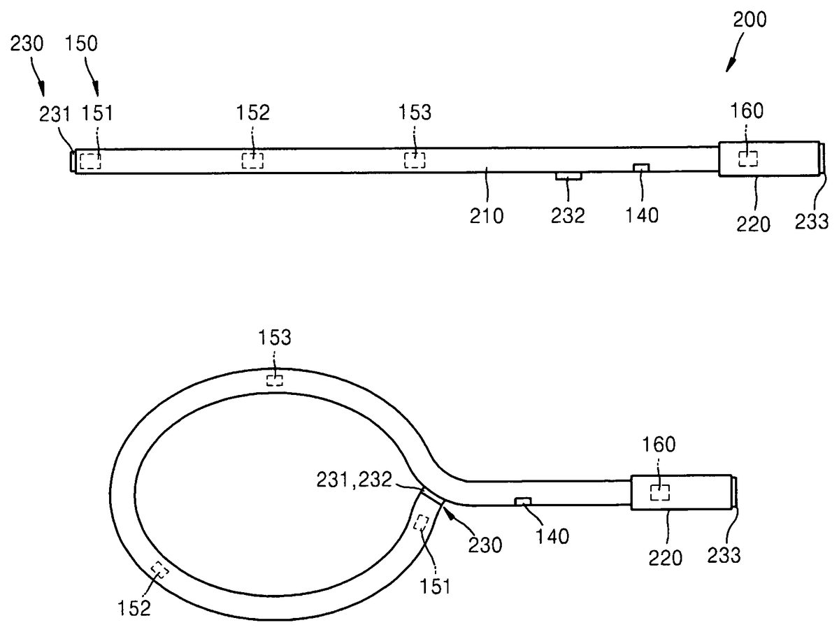
FIG. 8illustrates a game controller200according to another embodiment of the present invention.FIG. 9illustrates an example of a deformable shape of a first body portion210of the game controller200ofFIG. 8.
Referring toFIGS. 8 and 9, a coupling unit230includes first and second coupling units231and232formed in the first body portion210. A third coupling unit233may be further formed in the second body portion220. The game controller200is the same as the game controller100ofFIG. 7except for the position of the coupling unit230, and thus a description thereof will not be repeated here.
As the first and second coupling units231and232that can be coupled to each other are formed in the first body portion210itself, the game controller200may be deformed to have a racket shape as illustrated inFIG. 9as the first and second coupling units231and232of the first body portion210are coupled to each other. In this case, the first and second coupling units231and232may sense motion of the game controller200created when it is swung like a racket, and the second body portion220may function as a grip of the racket. Meanwhile, the reaction force generating unit160formed in the second body portion220may realize a sensation of hitting a ball with a racket.
FIG. 10illustrates a game system according to an embodiment of the present invention.FIG. 11is a block diagram illustrating the game system ofFIG. 10.
Referring toFIGS. 10 and 11, the game system includes a game controller310, a game machine320, and a display device330.
The game controller310may be the game controller100or200described with reference toFIGS. 1 through 9. The game controller310includes an input unit311like the manipulation button140ofFIG. 1or the moving state detection unit150and a transmission/reception unit315that transmits or receives data to/from the game machine320. Furthermore, as described above, the game controller310may include the reaction force generating unit160that improves a touch sensation for a user.
The game machine320may include a transmission/reception unit321transmitting/receiving data to/from the game controller310, a calculation unit executing game programs (i.e., a computer), and an input/output unit325outputting game contents as an image or a sound signal. The game machine320may be an exclusive game device or an all-purpose computer. When the game controller310includes the reaction force generating unit160that improves the touch sensation for the user as described above, the game machine320may transmit an appropriate reaction force signal to the game controller310according to the contents of the games.
The display device330may include an input/output unit receiving an image signal and a sound signal transmitted by the game machine320, a display unit333displaying an image according to the image signal, and a speaker335outputting a sound according to the sound signal. Alternatively, the speaker335may be included separately.
Wireless transmission/reception between the game controller310and the game machine320is illustrated inFIG. 11, but the game controller310and the game machine320may also be connected to each other via a wire. Also, the game machine320and the display device330may be connected in a wired or wireless manner. The game machine320and the display device330are separately formed inFIG. 11but may also be formed as a single unit according to circumstances.
FIG. 12illustrates a game system according to another embodiment of the present invention.FIG. 13is a block diagram illustrating the game system ofFIG. 12.
Referring toFIGS. 12 and 13, the game system includes a game machine410and a display device430. The game machine410includes an input unit411, a reaction force generating unit413, a calculation unit415(i.e., a computer), and a transmission/reception unit417. The game machine410according to the current embodiment may be regarded as a device that is formed of the game controller310and the game machine320formed as a single unit described with reference toFIGS. 10 and 11. The game machine410may have substantially the same configuration as that of the game controller100or200of the embodiments described with reference toFIGS. 1 through 9. In addition, the calculation unit415executing game programs is mounted in a body portion of the game machine410.
The display device430includes an input/output unit431receiving an image signal and a sound signal transmitted by the game machine410, a display unit433displaying an image according to the image signal, and a speaker435outputting a sound according to the sound signal. Alternatively, the speaker435may be included separately. Wireless transmission/reception between the game machine410and the display device430is illustrated inFIG. 13, but the game machine410and the display device430may also be connected via a wire according to circumstances.
According to the current embodiment, the game machine410and the display device430are separated but the embodiment is not limited thereto. The display device430may be mounted in the game machine410such that the game machine410may be used as a mobile device. In this case, the display device430may be installed in the second body portion120or220of the above-described embodiments which is not deformable, but the embodiment is not limited thereto. For example, if the display device430is a flexible display device, the display device430may be installed in a deformable body portion like the second body portion120or220of the above-described embodiments.
In the above-described embodiments of the present invention, the game controllers100,200, and310or the game machine410may be deformed so as to reduce the size of the first body portion110ofFIG. 1or the first body portion210ofFIG. 8by as much as possible, thereby improving convenience in regard to storage or portability.
While the present invention has been particularly shown and described with reference to exemplary embodiments thereof, it will be understood by those of ordinary skill in the art that various changes in form and details may be made therein without departing from the spirit and scope of the present invention as defined by the following claims.
Claims
- A game controller to manipulate a game program, comprising: a first body portion that is bendable, deformable, and configured to have a plurality of forms different from each other, the first body portion comprising a first end and a second end;a second body portion connected to the second end of the first body portion;a first coupling portion formed at the first end of the first body portion;a second coupling portion formed on the first body portion;a third coupling portion formed on the second body portion;and at least one of a sensor and an input unit formed in a bendable portion of the first body portion, wherein the first coupling portion is configured to be coupled to the second coupling portion in response to the first body portion being bent in a first configuration;wherein the first coupling portion is configured to be coupled to the third coupling portion in response to the first body portion being bent in the second configuration;and wherein the input unit further comprises a moving state detection sensor formed in at least one of the first body portion and the second body portion to detect a moving state of the game controller.
- The game controller of claim 1 , wherein the first body portion comprises a multi-joint structure.
- The game controller of claim 2 , wherein the multi-joint structure is fixable.
- The game controller of claim 1 , wherein the plurality of forms comprise at least two forms selected from the group consisting of a straight line, a shape having two linear portions bent in different directions, a circle, and a circle having a grip.
- The game controller of claim 1 , wherein the first body portion comprises a reaction force generating unit to generate a reaction force according to contents of a game.
- The game controller of claim 1 , wherein an input unit including at least one manipulation button to manipulate a game is formed in at least one of the first body portion and the second body portion.
- The game controller of claim 1 , wherein at least one of the first body portion and the second body portion comprises a vibration unit to generate vibration according to contents of a game.
- The game controller of claim 1 , wherein at least one of the first body portion and the second body portion comprises a transmission/reception unit to transmit/receive data to/from a computer executing the game program.
- The game controller of claim 1 , wherein at least one of the first body portion and the second body portion comprises an embedded computer configured to execute the game program.
- The game controller of claim 1 , wherein the second body portion is not capable of being deformed.
- A game machine comprising: a first body portion that is bendable and deformable to have a plurality of forms different from each other, the first body portion comprising a first end and a second end;an input unit comprising at least one manipulation button to manipulate a game, wherein the at least one manipulation button is installed in a bendable portion of the first body portion;a second body portion connected to the second end of the first body portion;a first coupling portion formed at the first end of the first body portion;a second coupling portion formed on the first body portion;a third coupling portion formed on the second body portion;and a computer installed inside the first body portion or the second body portion, and configured to execute a game program according to a game manipulation signal input by the input unit, wherein the first coupling portion is configured to be coupled to the second coupling portion in response to the first body portion being bent in a first configuration;wherein the first coupling portion is configured to be coupled to the third coupling portion in response to the first body portion being bent in the second configuration;and wherein the input unit further comprises a moving state detection sensor formed in at least one of the first body portion and the second body portion to detect a moving state of the game controller.
- The game machine of claim 11 , wherein the first body portion comprises a multi-joint structure.
- The game machine of claim 12 , wherein the plurality of forms comprise at least two forms selected from the group consisting of a straight line, a shape having two linear portions bent in different directions, a circle, and a circle having a grip.
- The game machine of claim 12 , wherein the multi-joint structure is fixable.
- The game machine of claim 12 , further comprising a display device to display characteristics of the game program executed in the computer.
- The game machine of claim 12 , wherein the game machine is a mobile device.
- A game system comprising: a game controller configured to manipulate a game program, the game controller comprising: a first body portion that is bendable, deformable, and configured to have a plurality of forms different from each other, the first body portion comprising a first end and a second end;a second body portion connected to the second end of the first body portion;a first coupling portion formed at the first end of the first body portion;a second coupling portion formed on the first body portion;a third coupling portion formed on the second body portion;a moving state detection sensor formed in at least one of the first body portion and the second body portion to detect a moving state of the game controller;a computer configured to execute the game program according to a manipulation signal transmitted by the game controller;and a display device connected to the computer in a wired or wireless manner to output an image output by the computer, wherein the first coupling portion is configured to be coupled to the second coupling portion in response to the first body portion being bent in a first configuration, and wherein the first coupling portion is configured to be coupled to the third coupling portion in response to the first body portion being bent in the second configuration.
- A game controller for manipulating a game program, comprising: a first body portion configured to bend and deform according to contents of a game, the first body portion comprising a multi-joint structure having a first end and a second end;a second body portion connected to the second end of the first body portion;a first coupling portion formed at the first end of the first body portion;a second coupling portion formed on the first body portion;a third coupling portion formed on the second body portion;and at least one of a sensor and an input unit formed in a bendable portion of the body portion, wherein the first coupling portion is configured to be coupled to the second coupling portion in response to the first body portion being bent to configure the game controller in a racquet shape, and wherein the first coupling portion is configured to be coupled to the third coupling portion in response to the first body portion being bent to configure the game controller in a circular shape;and wherein the input unit further comprises a moving state detection sensor formed in at least one of the first body portion and the second body portion to detect a moving state of the game controller.
- The game controller of claim 18 , further comprising: a second body portion that is not capable of being deformed, wherein bending and deformation of the first body portion allow the body portion to bend into a form comprising a straight line and a shape having two linear portions bent in different directions.
Disclaimer: Data collected from the USPTO and may be malformed, incomplete, and/or otherwise inaccurate.