Illustrative Figure
Abstract
A game controller comprises a top casing, a bottom casing, a circuitry board, and a plurality of rechargeable batteries. The top casing comprises different type of control components, at least two speakers and a plurality of solar panel. The bottom casing comprises a locking mechanism, plurality of trigger buttons, headphone jack and a USB port. A handheld device can be inserted into the present invention and secured from the locking mechanism. The handheld device can be connected to the present invention wirelessly with a control application or a USB data cable can be used. The different type of control buttons and the trigger buttons controls the input commands of the present invention.
Description
DETAIL DESCRIPTIONS OF THE INVENTION All illustrations of the drawings are for the purpose of describing selected versions of the present invention and are not intended to limit the scope of the present invention. The present invention, a Game Controller, comprises a top casing1, a bottom casing2, a circuitry board3, and a plurality of rechargeable batteries4. The circuitry board3and the plurality of rechargeable batteries4are positioned inside the bottom casing2. The top casing1is connected to the bottom casing2. The plurality of rechargeable batteries4is the primary power source of the present invention. The plurality of rechargeable batteries4is electronically connected to the circuitry board3. The plurality of rechargeable batteries4is charged by an external power cord which is connected between a power outlet and the present invention. The top casing1is designed as a shell and has an elongated “U” shape design. The top easing1has a left vertical section, a right vertical section, and a horizontal section. The top casing1is made out of high strength plastic so the weight of the top casing1can be minimized, the bottom easing being connected to the top casing from below. The top and bottom casings,1and2, are joined to form not more than a three sided open U-shaped structure with an absence of structure between the vertical portions of the U-shaped structure. This structure accommodates a handheld tablet that nests therein, as shown byFIG. 6, such that the handheld tablet is confined by the open U-shaped three sided structure. The plurality of menu buttons11comprises a select button111and a start button112. The select button111is positioned at the left vertical section of the top casing1adjacent to the at least two joysticks14. The start button112is positioned at the right vertical section of the top casing1adjacent to the at least two joysticks14. Both select button111and the start button112have a circular shape design. The select ...
DETAIL DESCRIPTIONS OF THE INVENTION
All illustrations of the drawings are for the purpose of describing selected versions of the present invention and are not intended to limit the scope of the present invention.
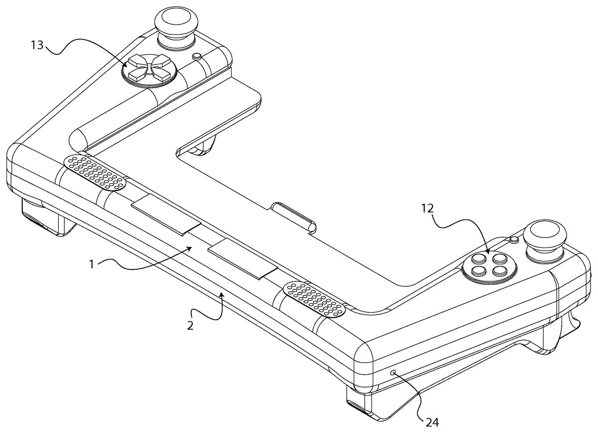
The present invention, a Game Controller, comprises a top casing1, a bottom casing2, a circuitry board3, and a plurality of rechargeable batteries4. The circuitry board3and the plurality of rechargeable batteries4are positioned inside the bottom casing2. The top casing1is connected to the bottom casing2. The plurality of rechargeable batteries4is the primary power source of the present invention. The plurality of rechargeable batteries4is electronically connected to the circuitry board3. The plurality of rechargeable batteries4is charged by an external power cord which is connected between a power outlet and the present invention. The top casing1is designed as a shell and has an elongated “U” shape design. The top easing1has a left vertical section, a right vertical section, and a horizontal section. The top casing1is made out of high strength plastic so the weight of the top casing1can be minimized, the bottom easing being connected to the top casing from below. The top and bottom casings,1and2, are joined to form not more than a three sided open U-shaped structure with an absence of structure between the vertical portions of the U-shaped structure. This structure accommodates a handheld tablet that nests therein, as shown byFIG. 6, such that the handheld tablet is confined by the open U-shaped three sided structure.
The plurality of menu buttons11comprises a select button111and a start button112. The select button111is positioned at the left vertical section of the top casing1adjacent to the at least two joysticks14. The start button112is positioned at the right vertical section of the top casing1adjacent to the at least two joysticks14. Both select button111and the start button112have a circular shape design. The select button111has the word “SELECT” written on top and similarly the start button112ahs the word “START” written on top. The plurality of menu buttons11is electronically connected to the circuitry board3. The main functionality of the select button111to selects certain functions within the present invention. For an example, correct applications or certain features within an application can be selected from the select button111. The start button112is the designated starting button on any kind of application. For an example, many gaming application has a starting point and the start button112can be easily used as the input command for the starting point. The plurality of menu buttons11is made out of materials that are capable of withstanding the constant movements of the plurality of menu buttons11. These materials can be high strength plastic or metal.
The plurality of control buttons12are positioned below the start button112and connected to the right vertical section of the top casing1. The plurality of control buttons12comprises a left button121, a bottom button122, a right button123, and a top button124. The plurality of control buttons12are positioned ninety degrees apart from each other and have a circular shape design. The left button121has the letter “X” displayed on top and the left button121is tinted in blue color. The bottom button122has the letter “A” displayed on top and the bottom button122is tinted in green color. The right button123has the letter “B” displayed on the top and the right button123is tinted in red color.
The top button124has the letter “Y” displayed on top and the top button124is tinted in yellow color. The plurality of control buttons12is designed with the above symbolic letters and colors for straightforward directional purposes and aesthetically pleasing looks respectively. For an example, in an instruction section, the plurality of control buttons12can be identify as the “A” or “Y” which result into less complication and easy operation.
The plurality of control buttons12is electronically connected to the circuitry board3. The plurality of control buttons12is used to control different functionalities within a given application. For an example, a fighting game application have many different features like upper kick, lower kick, upper punch, and lower punch. Each one of these features can be assigned into each button in the plurality of control buttons12. The plurality of control buttons12is made out of materials like high strength plastic or metal that is capable of withstanding the constant movements of the plurality of control buttons12.
The directional pad13is positioned below the select button111and connected to the left vertical section of the top casing1. The directional pad13comprises a right arrow button131, a top arrow button132, a left arrow button133, and a bottom arrow button134. Each of the buttons in the directional pad13is designed into an arrow shape. The arrow shape is a combination of a square and an equilateral triangle. The equilateral triangle part of the each button is pointed inward and each button is positioned ninety degrees apart. The right arrow button131has a symbol of an arrow pointed towards the plurality of control buttons12. The top arrow button132has a symbol of an arrow pointed upward. The left arrow button133has a symbol of an arrow pointed towards the right arrow button131. The bottom arrow button134has a symbol of an arrow pointed downward. The directional pad13is electronically connected to the circuitry board3. The main functionality of the directional pad13is to select the correct input by moving up and down or left and right. For an example, if there is a list of input commands, the bottom arrow button134can be used to move downward within the list. The directional pad13also performs as the volume controller in the present invention. The volume control function can be selected from the select button111. Then the volume is increased or decreased with the use of the directional pad13. The directional pad13is made out of materials like high strength plastic or metal that is capable of withstanding the constant movements of the each button.
The at least two joysticks14are positioned on the top casing1. The at least two joysticks14comprises a first joystick141and a second joystick142. The first joystick141is connected to the left vertical section of the top casing1and above from the directional pad13. Similarly the second joystick142is connected to the right vertical section of the top casing1and above from the plurality of control buttons12. The first joystick141and the second joystick142have a cylindrical shape design which allows the first joystick141and the second joystick142to rotate in a complete circular manner. The at least two joysticks14are electronically connected to the circuitry board3. The at least two joysticks14are mainly used in gaming applications. The at least two joysticks14have the same functionality as the plurality of control buttons12and the directional pad13but some of the advance gaming applications requires the at least two joysticks14to be independent from as the plurality of control buttons12and the directional pad13. The at least two joysticks14are made out of high strength plastic or metal in order to compensate the constant movements.
The at least two speakers15are connected to the horizontal section of the top casing1. The at least two speakers15amplify the volume from the device been used in the present invention. The at least two speakers15are electronically connected to the circuitry board3. The plurality of solar panels16is positioned between the at least two speakers15and connected to the horizontal section of the top casing1. The plurality of solar panels16is electronically connected to the plurality of rechargeable batteries4. The plurality of solar panels16functions as the secondary power source to the present invention. The plurality of solar panels16constantly recharges the plurality of rechargeable batteries4as the power level decreases.
The bottom casing2is designed as a shell and has an elongated “U” shape design similar to the top casing1. The bottom casing2has a left vertical segment, a right vertical segment, and a horizontal segment. The left vertical segment and the right vertical segment have a unique design which fits firmly to the user's palms. This unique design provides secure connection to the present invention when the present invention is held by its users. The bottom casing2is made out of high strength plastic so the weight of the bottom casing2is minimized. The left vertical segment and the right vertical segment can be combined with a small rubber stripes to provide additional friction. The bottom casing2may be connected with a stand. The stand is connected to the back side of the bottom casing2so the present invention can be stored upright. The stand is positioned parallel to the bottom casing2to prevent any obstructions that the users might have while the present invention is being used. The stand can be extended out from the bottom casing2so the present invention can be placed on a surface. The color of the bottom casing2can be either white or black but not limited to white or black. The bottom casing2comprises a plurality of trigger buttons21, a plurality of screw holes23, a headphone jack24, and a universal serial bus port (USB port)25.
The plurality of trigger buttons21comprises a top left button211, a bottom left button212, a top right button213, and a bottom right button214. The top left button211is positioned towards the upper part of the left vertical segment in the bottom casing2. The bottom left button212is positioned below the top left button211. The top right button213is positioned towards the upper part of the right vertical segment in the bottom casing2. The bottom right button214is positioned below the top right button213. Both top left buttons211and the top right button213have a flat top surface. Both bottom left button212and the bottom right button214have a curved top surface. Both the flat surface and the curve surface are designed in a way, so the users are able to fully interact with the plurality of trigger buttons21. The plurality of trigger buttons21is made out high strength plastic and electronically connected to the circuitry board3. The plurality of screw holes23is positioned in the bottom casing. The plurality of screw holes is aligned with the top casing1so the bottom casing2can be securely connected. Plurality of small screws is threaded into the plurality of screw hole23which connects with the top casing2. The headphone jack24and the universal serial bus port (USB port)25are laterally positioned around the bottom casing2. An external headphone set can be used when the external headphone set is inserted into the headphone jack24. The universal serial bus port (USB port)25connects to an external UBS power cord. The external USB power cord which is connected to an electric outlet recharges the plurality of rechargeable batteries4. The headphone jack24and the universal serial bus port (USB port)25are electronically connected to the circuitry board3. The universal serial bus port (USB port)25opens up a connection port from the present invention to the handheld device therefore the present invention can be connected via the universal serial bus port (USB port)25. The present invention also comprises a control application which can be downloaded into the handheld devices. The control application connects the present invention and the handheld devices with a simple wireless connection. Users of the present invention have two connecting options with handheld devices and users can choose either one of those connections upon their preference.
The circuitry board3connected all of the input and the output data of the present invention. The circuitry board3comprises a plurality of electrolytic capacitors31, a plurality of capacitors32, a plurality of switches33, a plurality of resistors34, a plurality of variable resistors35, a crystal resonator36, a plurality of IC chips37and a IR signal controller38. The plurality of electrolytic capacitors31is electronically connected to the plurality of capacitors32and the plurality of resistors34. The crystal resonator36is electronically connected to the plurality of capacitors32. The crystal resonator36, the plurality of resistors34, and the plurality of variable resistors35are electronically connected to the plurality of IC chips37. The plurality of IC chips37and the plurality of switches33are electronically connected to the circuitry board3. The IR signal controller38is electronically connected to the circuitry board3which provides an IR signal for any kind of wireless connection.
Although the invention has been explained in relation to its preferred embodiment, it is to be understood that many other possible modifications and variations can be made without departing from the spirit and scope of the invention as hereinafter claimed.
Claims
- A Game Controller comprises, a top casing;a bottom casing;a circuitry board;a plurality of rechargeable batteries;the top casing comprises a plurality of menu buttons, a plurality of control buttons, a directional pad, at least two joysticks, at least two speakers;the bottom casing comprises a plurality of trigger buttons, a plurality of screw holes, a headphone jack, and a universal serial bus port (USB port);the plurality of screw holes being aligned with the top casing;and the bottom casing being connected to the top casing from below, the top and bottom casings joined to form not more than a three sided open U-shaped structure with an absence of structure between the vertical portions of the U-shaped structure in which a handheld tablet nests, such that the handheld tablet is confined by the open U-shaped three sided structure.
- The Game Controller as claimed in claim 1 comprises, the circuitry board being positioned inside the bottom casing;the plurality of rechargeable batteries being positioned inside the bottom casing;and the circuitry board being electronically connected to the plurality of rechargeable batteries.
- The Game Controller as claimed in claim 1 comprises, the plurality of menu buttons comprises a select button and a start button;the select button being positioned on the top casing from an end;the start button being oppositely positioned on the top easing from the select button;the plurality of control buttons being positioned on the top casing below the start button;and the directional pad being positioned on the top casing opposite from the plurality of control buttons.
- The Game Controller as claimed in claim 3 comprises, the select button being electronically connected to the circuitry board;the start button being electronically connected to the circuitry board;the plurality of control buttons being electronically connected to the circuitry board;and the directional pad being electronically connected to the circuitry board.
- The Game Controller as claimed in claim l comprises, the at least two joysticks comprises a first joystick and a second joystick;the first joystick being positioned on the top casing, above from the directional pad;the second joystick being positioned on the top casing above from the plurality of control buttons;the at least two speakers being positioned on the top casing below the directional and the plurality of control buttons;and the plurality solar panels being positioned on the top casing adjacent the at least two speakers.
- The Game Controller as claimed in claim 5 comprises, the first joystick being electronically connected to the circuitry board;the second joystick being electronically connected to the circuitry board;the at least two speakers being electronically connected to the circuitry board;and the plurality of solar panels being electronically connected to the circuitry board.
- The Game Controller as claimed in claim 1 comprises, the plurality of trigger buttons comprise a top left button, a bottom left button, a top right button, and a bottom right button;the top left button and the bottom left button being positioned in the bottom casing perpendicular to the first joystick;and the top right button and the bottom right button being oppositely positioned from the top left button and the bottom left button;the headphone jack and the universal serial bus port (USB port) being laterally positioned around the bottom casing;and the headphone jack and the universal serial bus port (USB port) being electronically connected to the circuitry board.
- The Game Controller as claimed in claim l comprises, the circuitry board comprises a plurality of electrolytic capacitors, a plurality of capacitors, a plurality of switches, a plurality of resistors, a plurality of variable resistors, a crystal resonator, a plurality of IC chips, and a IR signal controller;the plurality of electrolytic capacitors being electronically connected to the plurality of capacitors and the plurality of resistors;the crystal resonator being electronically connected to the plurality of capacitors;the crystal resonator and the plurality of resistors being electronically connected to the plurality of IC chips;the plurality of variable resistors being electronically connected to the plurality of IC chips;the plurality of switches being electronically connected to the circuitry board;the plurality of IC chips being electronically connected to the circuitry board;and the IR signal controller being electronically connected to the circuitry board.
- A Game Controller comprises, a top casing;a bottom casing;a circuitry board;a plurality of rechargeable batteries;the top casing comprises a plurality of menu buttons, a plurality of control buttons, a directional pad, at least two joysticks, at least two speakers, and a plurality of solar panels;the bottom casing comprises a plurality of trigger buttons, a plurality of screw holes, a headphone jack, and a universal serial bus port (USB port);the plurality of screw holes being aligned with the top casing;the bottom casing, being connected to the top casing from below, the top and bottom casings joined to tort not more than a three sided open U-shaped structure with an absence of structure between the vertical portions of the U-shaped structure in which a handheld tablet nests, such that the handheld tablet is confined by the open U-shaped three sided structure;the circuitry board being positioned inside the bottom casing;the plurality of rechargeable batteries being positioned inside the bottom casing;and the circuitry board being electronically connected to the plurality of rechargeable batteries.
- The Game Controller as claimed in claim 9 comprises, the plurality of menu buttons comprises a select button and a start button;the select button being positioned on the top casing from an end;the start button being oppositely positioned on the top casing from the select, button;the plurality of control buttons being positioned on the top casing below the start button;and the directional pad being positioned on the top casing opposite from the plurality of control buttons.
- The Game Controller as claimed in claim 10 comprises, the select button being electronically connected to the circuitry board;the start button being electronically connected to the circuitry board;the plurality of control buttons being electronically connected to the circuitry board;and the directional pad being electronically connected to the circuitry board.
- The Game Controller as claimed in claim 9 comprises, the at least two joysticks comprises as first joystick and a second joystick;the first joystick being positioned on the top casing above from the directional pad;the second joystick being positioned on the top casing above from the plurality of control buttons;the at least two speakers being positioned on the top casing below the directional pad and the plurality of control buttons;and the plurality of solar panels being positioned on the Lop casing adjacent to the at least two speakers.
- The Game Controller as claimed in claim 12 comprises, the first joystick being electronically connected to the circuitry board;the second joystick being electronically connected to the circuitry board;the at least two speakers being electronically connected to the circuitry board;and the plurality of solar panels being electronically connected to the circuitry board.
- The Game Controller as claimed in claim 12 comprises, the plurality of trigger buttons comprise a top left button, a bottom left button, a top right button, and a bottom right button;the top left button and the bottom left button being positioned in the bottom casing perpendicular to the first joystick;and the top right button and the bottom right button being oppositely positioned from the top left button and the bottom left button;the headphone jack and the universal serial bus port USB port) being laterally positioned around the bottom casing;and the headphone jack and the universal serial bus port (USB port) being electronically connected to the circuitry board.
- The Game Controller as claimed in claim 12 comprises, the circuitry board comprises a plurality of electrolytic capacitors, a plurality of capacitors, a plurality of switches, a plurality of resistors, a plurality of variable resistors, a crystal resonator, a plurality of IC chips, and a IR signal controller;the plurality of electrolytic capacitors being electronically connected to the plurality of capacitors and the plurality of resistors;the crystal resonator being electronically connected to the plurality of capacitors;the crystal resonator and the plurality of resistors being electronically connected to the plurality of IC chips;the plurality of variable resistors being electronically connected to the plurality of IC chips;the plurality of switches being electronically connected to the circuitry board;the plurality of IC chips being electronically connected to the circuitry board;and the IR signal controller being electronically connected to the circuitry board.
- A Game Controller comprises, a top casing;a bottom casing;a circuitry board;a plurality of rechargeable batteries;the top casing comprises a plurality of menu buttons, a plurality of control buttons, a directional pad, at least two joysticks, at least two speakers;the bottom casing comprises a plurality of trigger buttons, a plurality of screw holes, a headphone jack, and a universal serial bus port (USB port);the plurality of screw holes being aligned with the top casing;the bottom casing being connected to the top casing from below, the top and bottom casings joined to form not more than a three sided open U-shaped structure with an absence of structure between the vertical portions of the U-shaped structure in which a handheld tablet nests, such that the handheld tablet is confined by the open U-shaped three sided structure;the circuitry board being positioned inside the bottom casing;the plurality of rechargeable batteries being positioned inside the bottom casing;and the circuitry board being electronically connected to the plurality of rechargeable batteries.
- The Game Controller as claimed in claim 16 comprises, the plurality of menu buttons comprises a select button and a start button;the select button being positioned on the top casing from an end;the start button being oppositely positioned on the top casing from the select button;the plurality of control buttons being positioned on the top casing below the start button;the directional pad being positioned on the top casing opposite from the plurality of control buttons;the select button being electronically connected to the circuitry board;the start button being electronically connected to the circuitry board;the plurality of control buttons being electronically connected to the circuitry board;and the directional pad being electronically connected to the circuitry board.
- The Game Controller as claimed in claim 16 comprises, the at least two joysticks comprises as first joystick and a second joystick;the first joystick being positioned on the top casing above from the directional pad;the second joystick being positioned on the top casing above from the plurality of control buttons;the at least two speakers being positioned on the top casing below the directional pad and the plurality of control buttons;the plurality of solar panels being positioned on the top casing adjacent to the at least two speakers;the first joystick being electronically connected to the circuitry board;the second joystick being electronically connected to the circuitry board;the at least two speakers being electronically connected to the circuitry board;and the plurality of solar panels being electronically connected to the circuitry board.
- The Game Controller as claimed in claim 16 comprises, the plurality of trigger buttons comprise a top left button, a bottom left button, as top right button, and a bottom right button;the top left button and the bottom left button being positioned in the bottom casing perpendicular to the first joystick;and the top right button and the bottom right button being oppositely positioned from the top left button and the bottom left button;the headphone jack and the universal serial bus port (USB port) being laterally positioned around the bottom casing;and the headphone jack and the universal serial bus port (USB port) being electronically connected to the circuitry board.
- The Game Controller as claimed in claim 16 comprises, the circuitry board comprises a plurality of electrolytic capacitors, a plurality of capacitors, a plurality of switches, a plurality of resistors, a plurality of variable resistors, a crystal resonator, a plurality of IC chips, and a IR signal controller;the plurality of electrolytic capacitors being electronically connected to the plurality of capacitors and the plurality of resistors;the crystal resonator being electronically connected to the plurality of capacitors;the crystal resonator and the plurality of resistors being electronically connected to the plurality of IC chips;the plurality of variable resistors being electronically connected to the plurality of IC chips;the plurality of switches being electronically connected to the circuitry board;the plurality of IC chips being electronically connected to the circuitry board;and the IR signal controller being electronically connected to the circuitry board.
Disclaimer: Data collected from the USPTO and may be malformed, incomplete, and/or otherwise inaccurate.