U.S. Pat. No. 8,986,112
System and method for downloading video game programs
AssigneeNintendo Co., Ltd.
Issue DateOctober 16, 2009
Illustrative Figure
Abstract
An example video game program download system and method apparatus for downloading a video game program to a target video game platform in which a processing system receives a download request from the target video game platform requesting downloading of a video game program that executes on a native video game platform different than the target video game platform. In response thereto, the requested video game program is sent along with a program for providing compatibility between the target and native video game platforms.
Description
DETAILED DESCRIPTION OF NON-LIMITING EXAMPLE EMBODIMENTS FIG. 1is a block diagram of a non-limiting example video game program download system100in which video game programs are downloaded over a wide area network (WAN)110such as the internet from a server108to one or more of a video game system102, a video game system104and a personal computer106. Video game system102, video game system104, personal computer106and server108are connected to wide area network110via respective links112,114,116and118. These links may, for example, be dial-up or network links (e.g., via a cable modem) to an internet service provider (ISP), links to wireless access points and the like. By way of example without limitation, video game system102is a Wii™ video game console and video game system104is a DS™ hand-held video game machine, both from Nintendo®. By way of further example without limitation, personal computer106is a conventional PC optionally configured with high-performance CPU(s) and graphics and audio processors for enhanced video game capabilities. WhileFIG. 1shows one video game system102, one video game system104and one personal computer106, it will be readily apparent that multiple systems of each type may be present in system100. Moreover, many different types of hand-held and console video game systems and personal computers may be used system100. It is also possible to provide separate servers for each type of video game system. For example, all video game consoles of a particular type (e.g., all Wii video game consoles) may be connected to a first server and all hand-held systems of a particular type (e.g., all DS hand-held video game machines) may be connected to a second different server. The discussion below makes specific reference to downloading video game programs to video game system102, which in this example is a video game console. However, it will be appreciated that the systems and methods described herein are readily applicable to ...
DETAILED DESCRIPTION OF NON-LIMITING EXAMPLE EMBODIMENTS
FIG. 1is a block diagram of a non-limiting example video game program download system100in which video game programs are downloaded over a wide area network (WAN)110such as the internet from a server108to one or more of a video game system102, a video game system104and a personal computer106. Video game system102, video game system104, personal computer106and server108are connected to wide area network110via respective links112,114,116and118. These links may, for example, be dial-up or network links (e.g., via a cable modem) to an internet service provider (ISP), links to wireless access points and the like.
By way of example without limitation, video game system102is a Wii™ video game console and video game system104is a DS™ hand-held video game machine, both from Nintendo®. By way of further example without limitation, personal computer106is a conventional PC optionally configured with high-performance CPU(s) and graphics and audio processors for enhanced video game capabilities. WhileFIG. 1shows one video game system102, one video game system104and one personal computer106, it will be readily apparent that multiple systems of each type may be present in system100. Moreover, many different types of hand-held and console video game systems and personal computers may be used system100. It is also possible to provide separate servers for each type of video game system. For example, all video game consoles of a particular type (e.g., all Wii video game consoles) may be connected to a first server and all hand-held systems of a particular type (e.g., all DS hand-held video game machines) may be connected to a second different server.
The discussion below makes specific reference to downloading video game programs to video game system102, which in this example is a video game console. However, it will be appreciated that the systems and methods described herein are readily applicable to downloading video game programs to hand-held video game machines and/or to personal computers running video game programs.
Server108stores (or has access to) video game programs for one or more different video game platforms. By way of example without limitation, server108may store video game programs for the Nintendo Entertainment System (NES), Super Nintendo Entertainment System (SNES) and Nintendo 64 (N-64) game systems. These video game programs may be selectively downloaded to video game system102, video game system104and/or personal computer106in response to requests generated by inputs thereto. For example, video game system102may contact server108over the wide area network110to receive display data for generating a menu of video game programs for display on an associated display device (e.g., a television). A user may make a selection from this menu using an input device (e.g., game controller). In response, the selected video game program is downloaded over wide area network110to video game system102where the video game program is stored in memory (e.g., on-board flash memory).
In one example embodiment, server108may in fact be made up of multiple servers. By way of example without limitation, server108may include a video game program server for storing video game programs and responding to requests from video game systems for downloading selecting ones of the video game programs thereto. Server108may also include an account management server for managing the accounts of the users of the download system. These different servers may run on the same computer system or each server may run on one or more different interconnected computer systems.
The game programs stored on server108are generally not directly executable by the game program executing system of, for example, video game system102. Consequently, server108stores (or has access to) programs that provide compatibility between the video game programs and game system102. Emulators are an example of programs that provide such compatibility. A particular emulator may be associated with one or more or all video games for a particular platform. For example, one emulator may be game-specific, i.e., developed so that a specific game can be executed on a particular target platform. Other emulators may be used to execute multiple games on a particular target platform. Still other emulators may be used to execute all games on a particular target platform.
Server108“bundles” an emulator with a selected game so that the selected game can be executed by the video game executing system of the target game system, in this case video game system102. Thus, the selection by a player of a video game program for downloading results in both that video game program and an emulator being downloaded to game system102. The user need not make any separate selection of an emulator. The video game program executing system of game system102executes the emulator program so that the game corresponding to the selected video game program can be played on game system102. The downloading and execution of the emulator program can be hidden from the user. That is, the selection of the video game program causes the game server to bundle the emulator with the selected video game program and a selection to play a game causes execution of the emulator.
FIG. 2shows a non-limiting example video game system102including a video game console200, a television202and a controller207.
Video game console200is a “target platform” for the downloaded video game programs and has a higher performance CPU and graphics processor than, for example, the “native platforms” for which video game programs downloaded from server108were developed (e.g., the Nintendo Entertainment System (NES), Super Nintendo Entertainment System (SNES) and Nintendo 64 (N-64) game systems). The download systems and methods described herein permit video games developed for these lower performance native platforms to be played on a high performance target platform. This provides significant versatility for the target platform since the target platform is able to execute video game programs developed for its high performance CPU and graphics processor as well as video game programs developed for earlier generation (e.g., less powerful) platforms. The emulators, which as noted above may be game-specific, allow the target platform to substantially recreate the gaming experience provided by the earlier generation platforms. As will be described below, the controller for video game console200has a connector to which controllers similar or even identical to the controllers for the earlier generation platforms can be connected, further enhancing the recreation of the gaming experience provided by the native platform.
Video game console200executes a game program or other application stored on optical disc204inserted into slot205formed in housing210thereof. The result of the execution of the game program or other application is displayed on display201of television202to which video game console200is connected by cable206. Audio associated with the game program or other application is output via speakers209of television202. While an optical disk is shown inFIG. 2, the game program or other application may alternatively or additionally be stored on other storage media such as semiconductor memories, magneto-optical memories, magnetic memories and the like.
Controller207wirelessly transmits data such as game control data to video game console200. The game control data may be generated using an operation section of controller207having, for example, a plurality of operation buttons, a key, a stick and the like. Controller207may also wirelessly receive data transmitted from video game console200. By way of example without limitation, this data may include sound data for output via a speaker (not shown) of controller207or vibration control data for controlling a vibration circuit (not shown) of controller207. Any one of various wireless protocols such as Bluetooth (registered trademark) may be used for the wireless transmissions between controller207and video game console200.
A “nunchuk” controller225may be connected to controller207. Although a wired connection is shown inFIG. 2between controller207and nunchuk controller225, a wireless connection may alternatively be used. Nunchuk controller225may be held in the user's “other” hand (i.e., the hand not holding controller207) and provides additional game control data to video game console200.
Controller207also includes an imaging information calculation section for capturing and processing images from light-emitting devices208aand208b. Although markers208aand208bare shown inFIG. 2as being above television screen201, they may also be positioned below television screen201. In one implementation, a center point between light-emitting devices208aand208bis substantially aligned with a vertical center-line of television screen201. The images from light-emitting devices208aand208bcan be used to determine a direction in which controller207is pointing as well as a distance of controller207from television screen201. By way of example without limitation, light-emitting devices208aand208bmay be implemented as two LED modules (hereinafter, referred to as “markers”) provided in the vicinity of screen201of television202. The markers each output infrared light and the imaging information calculation section of controller207detects the light output from the LED modules to determine a direction in which controller207is pointing and a distance of controller207from display screen201as mentioned above.
With reference to the block diagram ofFIG. 3, video game console200includes a RISC central processing unit (CPU)304for executing various types of applications including (but not limited to) video game programs. CPU304executes a boot program stored in a boot ROM (not shown) to initialize video game console200and then executes an application (or applications) stored on optical disc204, which is inserted in optical disk drive308. User-accessible eject button310provided on housing210of video game console200may be used to eject an optical disk from disk drive308.
In one example implementation, optical disk drive308receives both optical disks of a first type (e.g., of a first size and/or of a first data structure, etc.) containing applications developed to take advantage of the capabilities of CPU304and graphics processor (GPU)316and optical disks of a second type (e.g., of a second size and/or a second data structure) containing applications originally developed for execution by a CPU and/or graphics processor having capabilities different than those of CPU304and/or graphics processor316. For example, the optical disks of the second type may be applications originally developed for the Nintendo GameCube platform.
CPU304is connected to system LSI302that includes graphics processing unit316with an associated graphics memory320, audio digital signal processor (DSP)318, internal main memory322and input/output (IO) processor324.
IO processor324of system LSI302is connected to one or more USB ports326, one or more standard memory card slots (connectors)328, WiFi module330, flash memory332and wireless controller module340.
USB ports326are used to connect a wide variety of external devices to video game console200. These devices include by way of example without limitation game controllers, keyboards, storage devices such as external hard-disk drives and memory sticks, printers, digital still and video cameras and the like. USB ports326may also be used for wired and wireless network (e.g., LAN) connections. In one example implementation, two USB ports326are provided.
Standard memory card slots (connectors)328are adapted to receive industry-standard-type memory cards (e.g., SD memory cards). In one example implementation, one memory card slot328is provided. These memory cards are generally used as data carriers but of course this use is provided by way of illustration, not limitation. For example, a player may store game data for a particular game on a memory card and bring the memory card to a friend's house for use when the game is played on the friend's video game console. The memory cards may also be used to transfer data between the game console and personal computers, digital cameras, and the like. In the example download system described herein, downloaded video game programs may also be stored on memory cards connected to video game console200via connectors328.
WiFi module330enables video game console200to be connected to a wireless access point. The access point may provide internet connectivity for on-line gaming with players at other locations (with or without voice chat capabilities), as well as web browsing, e-mail, file downloads (including video game program downloads) and many other types of on-line activities. In some implementations, WiFi module may also be used for communication with other game devices such as suitably-equipped hand-held game machines (e.g., the DS hand-held game machine). Module330is referred to herein as “WiFi”, which is generally a designation used in connection with the family of IEEE 802.11 specifications. However, video game console200may alternatively or additionally use wireless modules that conform to other wireless standards.
Flash memory332stores, by way of example without limitation, game save data, system files, internal applications for the console and downloaded data (such as video game programs).
Wireless controller module340receives signals wirelessly transmitted from one or more controllers207and provides these received signals to IO processor324. The signals transmitted by controller207to wireless controller module340may include signals generated by controller207itself as well as signals generated by other devices such as nunchuk controller225that may be connected to controller207.
Wireless controller module340may also wirelessly transmit signals to controller207. By way of example without limitation, controller207(and/or another game controller connected thereto) may be provided with vibration circuitry and vibration circuitry control signals may be sent via wireless controller module340to control the vibration circuitry (e.g., by turning the vibration circuitry on and off). By way of further example without limitation, controller207may be provided with (or be connected to) a speaker (not shown) and audio signals for output from this speaker may be wirelessly communicated to controller207via wireless controller module340. By way of still further example without limitation, controller207may be provided with (or be connected to) a display device (not shown) and display signals for output from this display device may be wirelessly communicated to controller207via wireless controller module340.
Proprietary memory card slots346are adapted to receive proprietary memory cards. In one example implementation, two such slots are provided. These proprietary memory cards have some non-standard feature(s) such as a non-standard connector and/or non-standard memory architecture. For example, one or more of the memory card slots346may be adapted to receive memory cards used with the Nintendo GameCube platform. In this case, memory cards inserted in such slots can transfer data from games developed for the GameCube platform. In an example implementation, memory card slots346may be used for read-only access to the memory cards inserted therein and limitations may be placed on whether data on these memory cards can be copied or transferred to other storage media such as standard memory cards inserted into slots328.
One or more controller connectors344are adapted for wired connection to respective game controllers. In one example implementation, four such connectors are provided for wired connection to game controllers for the Nintendo GameCube platform. Alternatively, connectors344may be connected to respective wireless receivers that receive signals from wireless game controllers. These connectors enable players, among other things, to use controllers for the Nintendo GameCube platform when an optical disk for a game developed for this platform is inserted into optical disk drive308.
A connector348is provided for connecting game console200to DC power derived, for example, from an ordinary wall outlet. Of course, the power may be derived from one or more batteries.
GPU316performs image processing based on instructions from CPU304. GPU316includes, for example, circuitry for performing calculations necessary for displaying three-dimensional (3D) graphics. GPU316performs image processing using graphics memory320dedicated for image processing and a part of internal main memory322. GPU316generates image data for output to television202by audio/video connector314via audio/video IC (interface)312.
Audio DSP318performs audio processing based on instructions from CPU304. The audio generated by audio DSP318is output to television202by audio/video connector314via audio/video IC312.
External main memory306and internal main memory322are storage areas directly accessible by CPU304. For example, these memories can store an application program such as a game program read from optical disc204by CPU304, a downloaded video game program (and corresponding emulator) read from flash memory332by CPU304, various types of data or the like.
ROM/RTC338includes a real-time clock and preferably runs off of an internal battery (not shown) so as to be usable even if no external power is supplied. ROM/RTC338also may include a boot ROM and SRAM usable by the console.
Power button342is used to power video game console200on and off. In one example implementation, power button342must be depressed for a specified time (e.g., one or two seconds) to turn the video game console off so as to reduce the possibility of inadvertently turn-off. Reset button344is used to reset (re-boot) video game console200.
With reference toFIGS. 4A-4C, example controller207includes a housing401on which operating controls402a-402iare provided. Housing401has a generally parallelepiped shape and is sized to be conveniently grasped by a player's hand. Cross-switch402ais provided at the center of a forward part of a top surface of the housing401. Cross-switch402ais a cross-shaped four-direction push switch which includes operation portions corresponding to the directions designated by the arrows (front, rear, right and left), which are respectively located on cross-shaped projecting portions. A player selects one of the front, rear, right and left directions by pressing one of the operation portions of the cross-switch402a. By actuating cross-switch402a, the player can, for example, move a character in different directions in a virtual game world.
Cross-switch402ais described by way of example and other types of operation sections may be used. By way of example without limitation, a composite switch including a push switch with a ring-shaped four-direction operation section and a center switch may be used. By way of further example without limitation, an inclinable stick projecting from the top surface of housing401that outputs signals in accordance with the inclining direction of the stick may be used. By way of still further example without limitation, a horizontally slidable disc-shaped member that outputs signals in accordance with the sliding direction of the disc-shaped member may be used. By way of still further example without limitation, a touch pad may be used. By way of still further example without limitation, separate switches corresponding to at least four directions (e.g., front, rear, right and left) that output respective signals when pressed by a player can be used.
Buttons (or keys)402bthrough402gare provided rearward of cross-switch402aon the top surface of housing401. Buttons402bthrough402gare operation devices that output respective signals when a player presses them. For example, buttons402b,402cand402dare respectively an “X” button, a “Y” button and a “B” button and buttons402e,402fand402gare respectively a select switch, a menu switch and a start switch, for example. Generally, buttons402bthrough402gare assigned various functions in accordance with the application being executed by video game console200. In an exemplary arrangement shown inFIGS. 4A-4C, buttons402b,402cand402dare linearly arranged along a front-to-back centerline of the top surface of housing401. Buttons402e,402fand402gare linearly arranged along a left-to-right line between buttons402band402d. Button402fmay be recessed from a top surface of housing401to reduce the possibility of inadvertent pressing by a player grasping controller207.
Button402his provided forward of cross-switch402aon the top surface of the housing401. Button402his a power switch for remote on-off switching of the power to game console200. Button402hmay also be recessed from a top surface of housing401to reduce the possibility of inadvertent pressing by a player.
Multiple (e.g., four) LEDs404are provided rearward of button402con the top surface of housing401. Controller207is assigned a controller type (number) so as to be distinguishable from other controllers used with video game console200and LEDs404may be used to provide a player a visual indication of this assigned controller number. For example, when controller207transmits signals to wireless controller module340, one of the multiple LEDs corresponding to the controller type is lit up.
With reference toFIG. 4B, a recessed portion408is formed on a bottom surface of housing401. Recessed portion408is positioned so as to receive an index finger or middle finger of a player holding controller207. A button402iis provided on a rear, sloped surface408aof the recessed portion. Button402ifunctions, for example, as an “A” button which can be used, by way of illustration, as a trigger switch in a shooting game.
As shown inFIG. 4C, an imaging element405ais provided on a front surface of controller housing401. Imaging element405ais part of an imaging information calculation section of controller207that analyzes image data received from markers208aand208b. The imaging information calculation section has a maximum sampling period of, for example, about 200 frames/sec., and therefore can trace and analyze even relatively fast motion of controller207. Additional details may be found in application Ser. No. 11/532,328, filed on Sep. 15, 2006, which claims the benefit of Application No. 60/716,937, entitled “VIDEO GAME SYSTEM WITH WIRELESS MODULAR HANDHELD CONTROLLER,” filed on Sep. 15, 2005; application Ser. No. 11/445,280, filed Jun. 2, 2006, which claims the benefit of Application No. 60/732,648, entitled “INFORMATION PROCESSING PROGRAM,” filed on Nov. 3, 2005; and application Ser. No. 11/441,146, filed May 26, 2006 which claims the benefit of Application No. 60/732,649, entitled “INFORMATION PROCESSING SYSTEM AND PROGRAM THEREFOR,” filed on Nov. 3, 2005. The entire contents of each of these applications are expressly incorporated herein.
Connector403is provided on a rear surface of controller housing401. Connector403is used to connect devices to controller207. For example, a second controller of similar or different configuration may be connected to controller207via connector403in order to allow a player to play video games using game control inputs from both hands. Other devices including game controllers for other game consoles, input devices such as keyboards, keypads and touchpads and output devices such as speakers and displays may be connected to controller207using connector403.
One example device for connection to controller207via connector403is nunchuk controller225shown inFIG. 2. Nunchuk controller225includes, for example, an analog joystick and a trigger switch. If controller207is held in a user's right/left hand, nunchuk controller225is held in the user's left/right hand and may be used to provide additional user inputs to console video game console200. By way of example without limitation, controller207may be used to control a sword during gameplay and nunchuk controller225may be used to control a shield during the gameplay.
As shown in the block diagram ofFIG. 9, controller207includes a three-axis, linear acceleration sensor907that detects linear acceleration in three directions, i.e., the up/down direction (e.g., Z-axis direction), the left/right direction (e.g., X-axis direction), and the forward/backward direction (e.g., Y-axis direction). Alternatively, a two-axis linear accelerometer or a one-axis linear accelerometer may be used. Generally speaking, the accelerometer arrangement (e.g., three-axis or two-axis or one-axis) will depend on the type of control signals desired. As a non-limiting example, the three-axis or two-axis linear accelerometer may be of the type available from Analog Devices, Inc. or STMicroelectronics N.V. Preferably, acceleration sensor907is an electrostatic capacitance or capacitance-coupling type that is based on silicon micro-machined MEMS (micro-electromechanical systems) technology. However, any other suitable accelerometer technology (e.g., piezoelectric type or piezoresistance type) now existing or later developed may be used to provide three-axis or two-axis linear acceleration sensor907.
As one skilled in the art understands, linear accelerometers, as used in acceleration sensor907, are only capable of detecting acceleration along a straight line corresponding to each axis of the acceleration sensor. In other words, the direct output of acceleration sensor907is limited to signals indicative of linear acceleration (static or dynamic) along each of the two or three axes thereof. As a result, acceleration sensor907cannot directly detect movement along a non-linear (e.g. arcuate) path, rotation, rotational movement, angular displacement, tilt, position, attitude or any other physical characteristic.
However, through additional processing of the linear acceleration signals output from acceleration sensor907, additional information relating to controller207can be inferred or calculated (i.e., determined), as one skilled in the art will readily understand from the description herein. For example, by detecting static, linear acceleration (i.e., gravity), the linear acceleration output of acceleration sensor907can be used to determine tilt of the object relative to the gravity vector by correlating tilt angles with detected linear acceleration. In this way, acceleration sensor907can be used in combination with micro-computer902of controller207(or another processor) to determine tilt, attitude or position of controller207. Similarly, various movements and/or positions of controller207can be calculated through processing of the linear acceleration signals generated by acceleration sensor907when controller207containing acceleration sensor907is subjected to dynamic accelerations by, for example, the hand of a user.
In another embodiment, acceleration sensor907may include an embedded signal processor or other type of dedicated processor for performing any desired processing of the acceleration signals output from the accelerometers therein prior to outputting signals to micro-computer902. For example, the embedded or dedicated processor could convert the detected acceleration signal to a corresponding tilt angle (or other desired parameter) when the acceleration sensor is intended to detect static acceleration (i.e., gravity).
Returning toFIG. 9, imaging information calculation section905of controller207includes infrared filter928, lens929, imaging element905aand image processing circuit930. Infrared filter928allows only infrared light to pass therethrough from the light that is incident on the front surface of controller207. Lens929collects and focuses the infrared light from infrared filter928on imaging element905a. Imaging element905ais a solid-state imaging device such as, for example, a CMOS sensor or a CCD. Imaging element905acaptures images of the infrared light from markers208aand208bcollected by lens929. Accordingly, imaging element905acaptures images of only the infrared light that has passed through infrared filter928and generates image data based thereon. This image data is processed by image processing circuit920which detects an area thereof having high brightness, and, based on this detecting, outputs processing result data representing the detected coordinate position and size of the area to communication section906. From this information, the direction in which controller207is pointing and the distance of controller207from display screen201can be determined.
Vibration circuit912may also be included in controller207. Vibration circuit912may be, for example, a vibration motor or a solenoid. Controller207is vibrated by actuation of the vibration circuit912(e.g., in response to signals from video game console200), and the vibration is conveyed to the hand of the player grasping controller207. Thus, a so-called vibration-responsive game may be realized.
As described above, acceleration sensor907detects and outputs the acceleration in the form of components of three axial directions of controller207, i.e., the components of the up-down direction (e.g., Z-axis direction), the left-right direction (e.g., X-axis direction), and the front-rear direction (e.g., Y-axis direction) of controller207. Data representing the acceleration as the components of the three axial directions detected by acceleration sensor907is output to communication section906. Based on the acceleration data which is output from acceleration sensor907, a motion of controller207can be determined.
Communication section906includes micro-computer902, memory903, wireless module904and antenna905. Micro-computer902controls wireless module904for transmitting and receiving data while using memory903as a storage area during processing. Micro-computer902is supplied with data including operation signals (e.g., cross-switch, button or key data) from operation section902, acceleration signals in the three axial directions (X-axis, Y-axis and Z-axis direction acceleration data) from acceleration sensor907, and processing result data from imaging information calculation section905. Micro-computer902temporarily stores the data supplied thereto in memory903as transmission data for transmission to video game console200. The wireless transmission from communication section906to video game console200is performed at predetermined time intervals. Because game processing is generally performed at a cycle of 1/60 sec. (16.7 ms), the wireless transmission is preferably performed at a cycle of a shorter time period. For example, a communication section structured using Bluetooth (registered trademark) technology can have a cycle of 5 ms. At the transmission time, micro-computer902outputs the transmission data stored in memory903as a series of operation information to wireless module904. Wireless module904uses, for example, Bluetooth (registered trademark) technology to send the operation information from antenna905as a carrier wave signal having a specified frequency. Thus, operation signal data from operation section902, the X-axis, Y-axis and Z-axis direction acceleration data from acceleration sensor907, and the processing result data from imaging information calculation section905are transmitted from controller207. Video game console200receives the carrier wave signal and demodulates or decodes the carrier wave signal to obtain the operation information (e.g., the operation signal data, the X-axis, Y-axis and Z-axis direction acceleration data, and the processing result data). Based on this received data and the application currently being executed, CPU304of video game console200performs application processing. If communication section906is structured using Bluetooth (registered trademark) technology, controller207can also receive data wirelessly transmitted thereto from devices including video game console200.
FIG. 4Dshows an example of another type of controller that can be coupled to controller207via connector403. Controller450may be used, for example, as a controller for downloaded games played on video game console200that were originally developed for other gaming platforms. Controller450includes a cross-switch452that may be actuated to move a video game characters and objects in different up, down left and right directions. Analog sticks454and456may be used to move video game characters and objects in any direction (i.e., 360 degrees). Buttons458,459and460may be used, for example, to start, quit and pause game play. Buttons462,464,466and468may be used for perform character or object actions such as jumping, firing weapons, crawling, etc. Shoulder keys (not shown inFIG. 4D) may also be used to perform character or object actions. Inputs to controller450are sent to controller207via connector403and then to video game console200for processing.
FIG. 5shows by way of example without limitation a user interface for video game console200. This user interface is a channel menu that is displayed on television screen201and allows users to select one of a plurality of different “channels” for accessing various features of the console. The channel selection may be made by positioning an on-screen cursor using the optical position detection feature of controller207and then pressing “trigger” button402i. Of course, other techniques for making selections may be used and the systems and methods described herein are in no way limited in this respect.
Disc channel502allows users to play game discs inserted in optical disc drive308. As noted above, the inserted disc may contain games or other applications developed for video game console200or for a different console (e.g., the Nintendo GameCube).
Photo viewer channel504allows users to retrieve digital pictures from a memory card inserted into standard memory card slot(s)328of video game console200and display them on television screen201. Users also can manipulate the photos by, for example, zooming into details or creating mosaics, puzzles or slide shows. A song stored on the memory card may be played while, for example, a slide show is being presented.
Shopping channel506allows user to download video game content, including video game programs originally developed for other platforms (e.g., the aforementioned NES, SNES and N64 platforms). After users download games from shopping channel506, each downloaded game appears in the channel menu ofFIG. 5as its own channel. To play the downloaded game, users simply select the game's channel. InFIG. 5, channels514,516,518,520and522correspond to channels for downloaded games.
Forecast channel508allows users to access and display local weather forecasts (e.g., retrieved from the Internet) after turning on video game console200. The weather information can be automatically updated by accessing the Internet.
News channel510allows users to access and display local, national and world news (e.g., retrieved from the Internet), which may be organized into a variety of topical categories. The news can be automatically updated by accessing the Internet.
Internet channel512allows the user to access the internet to, for example, access web sites.
Right arrow526may be selected to move a different page of the channel menu. A left arrow (not shown) is present and may be selected when there are pages to the left of the current page.
FIG. 6shows an example memory map for flash memory332. The map ofFIG. 6is provided by way of example without limitation and the various programs may be readily organized in different manners and even using different and/or additional memories (e.g., memory cards inserted into standard memory card slot338).
Flash memory332stores a channel selection program602for generating and displaying the channel menu and allowing users to make selections from the menu. Channel selection program602includes, by way of example without limitation, a channel list, a display/select program and a selected channel start program.
Programs for each of the channels are also contained in memory332. Consequently, memory332includes disc channel program604, photoviewer channel program606, shopping channel program608, forecast channel program610, news channel program612and internet channel program614. As noted above, after users download video game programs from shopping channel506, each downloaded video game appears in the channel menu as its own channel. Thus, each of the downloaded games may be included in the channel list. Each downloaded video game program is stored in flash memory332along with a corresponding emulator program for providing compatibility between the native platform of the downloaded video game and the target platform (i.e., video game console200). When a particular one of the video game program is selected from the channel menu, that video game program and the corresponding emulator are loaded into internal/external memory306/322for execution by CPU304.
As shown inFIG. 7A, each game program stored in flash memory332includes by way of example without limitation a game title, a game control program, graphics data (and/or graphics processing program) and sound data (and/or a sound program). The emulator program for a given game converts the program architecture for that game from an architecture for the game program's native platform to a game program architecture suitable for the target platform (i.e., video game console200). As shown schematically inFIG. 7B, an example emulator program may include a first emulator for the CPU of the native platform and a second emulator for the graphics processing unit of the native platform. The emulator program can, for example, be realized by an instruction-word conversion table, etc. to convert an instruction for the native game platform into an instruction that is executable by the target video game platform. For example, the instructions “A”, “D” and “T” shown inFIG. 7Aare generally not directly executable by CPU304of video game console200. These instructions are converted by the emulator program into instructions “a1”, “b1” and “t1” which can be executed by CPU304. Of course, it may not always be the case that there is a one-to-one correspondence between instructions for the native platform and instructions for the target platform. Thus, an instruction for the native platform may in fact be converted into two or more instructions for the target platform.
Additional programs and information may be associated with downloaded video games. These additional programs and information are perhaps most conveniently incorporated into the emulator program for the downloaded video game program, but can easily be provided as separate programs or files. The systems and methods described herein are in no way limited by the manner in which additional programs and information are associated with downloaded video games.
By way of example, a user manual for the game may be downloaded. The manual may include information about the game, how to play the game, tips for playing the game, controller information, etc. By way of further example, a high score program may be included to communicate a user's high score to server108for comparison to high scores for other users. By way of still further example, a multi-player program may be provided so that games originally intended, for example, for play by one player can be played by two or more players. By way of still further example, a browser program may also be provided so that the user can navigate through the user manual.
A rental program may also be provided so that the video game program is usable for a specified period of time rather than being “purchased” (i.e., licensed for use for an unlimited period of time). By way of example, the video game program usability may be limited by playing time (e.g., forty hours of game playing time) or by real time (e.g., two months with no limit on the game playing time within those two months). Some games (e.g., previews for new games) may be available only on a rental basis. In other instances, certain games may be offered at one price for purchase and another (generally lower) price for rental. The rental program may be used to allow users to play a video game for a trial time period before deciding to purchase the corresponding video game program.
Flash memory332(or some other memory of video game console200) may also store a history of downloaded video games. In this way, if a particular game is deleted from flash memory332, the deleted video game program can be “re-downloaded” without the user having to re-purchase the program and incurring additional charges. A similar history can be alternatively or additionally maintained in a memory contained in or accessible to server108.
AlthoughFIG. 6shows downloaded games as being stored in flash memory332, these games may also be stored on memory cards (e.g., SD memory cards) inserted into memory card slot(s)328.
Various digital rights management (DRM) techniques may be used to control access and usage of the downloaded video games. For example, the downloaded video games may be “locked” to a particular video game console so that the video games can only be played on that console. As such, if a downloaded video game were downloaded and stored on a memory card, that memory card could not be inserted into a different video game console to play the game.
FIGS. 8A-8Dshow various non-limiting examples of data that can be downloaded from server108to video game system102.FIG. 8Ashows that a video game program and an emulator program for that video game program may “bundled” together for downloading. In an alternative implementation, the corresponding emulator program may already be stored by game system102(or be accessible thereto) and thus server108sends the video game program and an identifier for the emulator program to the game system102. Game system102may use the emulator program identifier to search for the emulator program in its own memory, in memory accessible thereto, or even on the internet.FIG. 8Cshows sending a list that relates video game programs to their corresponding emulators. Thus, when a user downloads a particular video game program from server108, video game system can use the list to identify and retrieve (e.g., from a web site) an emulator appropriate for the downloaded video game program.FIG. 8Dshows sending a first list relating video game programs to their native platforms and a second list of emulator programs and the platforms emulated by these emulators. Thus, if a user downloads a video game program for a particular platform, video game system102can use the lists ofFIG. 8Dto identify and retrieve an appropriate emulator program.
FIGS. 10A-10Eare a flow chart showing an example shopping channel process flow when the shopping channel506is selected from the channel menu shown inFIG. 5. The shopping channel allows users to, among other things, shop for and purchase (or possibly rent) video game programs. When the user finds a video program that he or she would like to download, the user selects the desired video game program. The selected video game program and its corresponding emulator are then downloaded to video game console200.
The process flow begins with the display of the channel menu ofFIG. 5at ST1001. When the shopping channel506is selected using controller207, the process determines at ST1002whether the shopping channel is undergoing maintenance. If so, a display to this effect is displayed at ST1003and the process returns to ST1001. If not, the process determines at ST1004whether a shopping channel update is available. If an update is available, a display prompting the user to obtain the update is displayed at ST1005and the user is invited to return to the shopping channel when the update is obtained. The process then returns to ST1001. The update may, for example, be an update to the shopping channel program stored in flash memory332that provides additional channels, new features, and the like.
If no update is available, the process determines at ST1006whether the country currently selected in the settings for video game console200has changed since the last time the user connected to the shopping channel. If so, the user is warned at ST1007that the country setting has changed and is asked to confirm that the new setting is okay. If the user confirms that the new setting is okay, the process proceeds to ST1008. Otherwise, the process returns to ST1001where the channel menu ofFIG. 5is displayed (i.e., the shopping channel program is ended).
At ST1008, the process determines whether the currently selected country is one in which the shopping channel is available. If the shopping channel is not available in the currently selected country, a display to this effect is displayed at ST1009and the process then returns to ST1001where the channel menu ofFIG. 5is displayed. If the shopping channel is available in the currently selected channel, the process determines at ST1010whether this is the first time the user has accessed the shopping channel. If so, the process provides a display at ST1011asking the user to wait until a connection is established with server108for initial settings processing at ST1013.
If this is not the first time the user has accessed the shopping channel the process proceeds from ST1010to ST1012where the process determines whether the current country setting is changed from the country setting the last time the shopping channel was accessed. If so, the process proceeds to the initial settings processing at ST1013. If not, the process proceeds to ST1014.
The initial settings processing allows the user to set various shopping channel options. For example, certain countries or regions may have so-called “loyalty” accounts where certain purchases may result in user benefits such as discounts on future purchases, free gifts for a certain amount of total purchases, etc. The initial settings processing allows a user to link his or her shopping channel account activities to this loyalty account. The initial settings processing also allows a user to delete his or her shopping channel account. The user may want to delete an account if, for example, the video game console associated with the account is being sold to another user. After initial settings processing, the process proceeds to ST1014.
At ST1014, a welcome screen is displayed. A non-limiting example welcome screen is shown inFIG. 11A. The welcome screen may contain links1100to one or more notices about product availability, pricing, shipping information and the like. The user may select one of the links1100whereby the process proceeds to ST1015to display the notice corresponding to the selected link. The display of the notice at ST1015includes a link for returning back to the display of the welcome screen. The welcome screen ofFIG. 11Aalso contains a “start shopping” link1101which can be selected by the user to proceed to the display of a shopping channel main screen at ST1016. The welcome screen also includes a number of banner icons1102-1,1102-2. . .1102-6showing video programs available for download. Selection of one of these banner icons provides a short-cut to ST1020for purchasing the video game program corresponding to the selected icon.
At ST1016, a shopping channel main screen is displayed. A non-limiting example main screen is shown inFIG. 11B. The main screen includes a link1103back to the welcome screen ofFIG. 11A. The main screen also includes links1104,1105,1106,1107and1108which cause the process to proceed to ST1017, ST1036, ST1037, ST1058and ST1060, respectively. Each of these steps of the process will be described in greater detail below.
At ST1017, a virtual console top (or main) page is displayed. A non-limiting example top main page is shown inFIG. 11D. The main page ofFIG. 11Dincludes links1117and1119to a video game program catalog page shown inFIG. 11F. Selecting link1117results in the video game programs on the catalog page being ordered in terms of their addition to the shopping channel while selecting link1119results in the video game programs on the catalog page being alphabetically ordered. Selecting link1116brings the user to a hardware select page, a non-limiting example of which is shown inFIG. 11E. Selecting link1114brings to the user to a help manual page, an example of which is shown inFIG. 11C. Selecting link1115brings the user back to the main screen ofFIG. 11B. Selecting link1121brings the user back to previous page. Link1122provides a display of shopping points and, if selected, brings the user to a shopping points top page, a non-limiting example of which is shown inFIG. 11M.
In response to the user selecting link1117at ST1017, the process proceeds to a video catalog display at ST1019which is ordered in terms of the times at which the games became available in the catalog. In response to the user selecting link1119at ST1017, the process proceeds to a video catalog display at ST1019which is alphabetically ordered. In response to the user selecting link1116at ST1017, the process proceeds to ST1018. At ST1018, the user selects a particular game platform and the process proceeds to a video catalog display at ST1019which is limited to available video game programs for the platform selected at ST1018.
The hardware selection screen ofFIG. 11Eshows graphical links1125-1,1125-2,1125-3,1125-4and1125-5, each of which corresponds to a different video game platform. Selecting one of these graphical links results in the video game catalog ofFIG. 11Fbeing limited to video game programs for the platform corresponding to the selected link. The screen ofFIG. 11Ealso includes a link1123for bringing the user to a help manual page and a link1124for bringing the user back to the main screen ofFIG. 11B. Link1126is for bringing the user back to previous page and link1127provides a display of shopping points and, if selected, brings the user to a shopping points top page.
In still other example implementations, the video game programs in the catalog can be ordered or listed/not listed on the basis of game characters, genre, publisher, parental rating or any other relevant characteristic of the video game programs.
The video game program catalog page shown inFIG. 11Fcontains multiple links1128-1,1128-2and1128-3, each of which corresponds to a different game. Link1128-1include a “new arrival icon” indicating that the corresponding video game program was recently added to the catalog (e.g., within some specified number of days before the current day), an update icon1130indicating the availability of an update for the corresponding video game program, a screen shot1131from the corresponding video game program, a platform designator1132designating the native platform for the corresponding video game program, publisher information1133identifying the publisher of the corresponding video game program and a price indicator1134indicating the purchase price of the corresponding game. In theFIG. 11Fexample, price is expressed in terms of points, where each point corresponds to an amount of money (e.g., $0.01). Of course, the price information may be displayed in various manners including as a monetary amount. If the game has already been purchased, a “purchased” indicator1135is provided in place of the price indicator. The video game program catalog page includes a scrolling bar for scrolling the display to see additional video game links on the page. The catalog may include multiple pages and these multiple pages are accessible using the left and right arrows1137aand1137b. A current page/total page indicator1138indicates the current page and the total number of pages (e.g., the indicator1138indicates that the user is viewing page 3 of 5 total pages). A back link1140brings the user back to the previous page and link1139provides a display of shopping points and, if selected, brings the user to a shopping points top page.
When the user selects one of the links on theFIG. 11Fscreen at ST1019, the process proceeds to ST1020. At ST1020, a software purchase screen is displayed, a non-limiting example of which is shown inFIG. 11G. The screen ofFIG. 11Gincludes game details such as a screen shot1141, general game information1142(e.g., video game release date, publisher information, number of players, game genre and the like), and controller icons1143,1144and1145indicating the types of controllers that can be used to play the game. The game details also include game rating information1146and selecting a rating icon brings the user to a rating information page, a non-limiting example of which is shown inFIG. 11I. TheFIG. 11Gscreen also includes a back link1148for bringing the user back to the previous page, a points display/link1149and a “more details” link1150that a user can select to find out additional details about the video game. A download link1147indicates the price of the game (e.g., 500 points). If the game has previously been purchased, the price indicator indicates that the game is “free” (e.g., 0 points).
If the user selects the “more details” link1150at ST1020, the process proceeds to ST1021. At ST1021, a “more details” screen is displayed, a non-limiting example of which is shown inFIG. 11H. If the user selects a rating icon1146at ST1020, the process proceeds to ST1022. At ST1022, a “rating information” screen is displayed, a non-limiting example of which is shown inFIG. 11I. If the user selects download link1147at ST1020, the process proceeds to ST1023.
The “more details” screen ofFIG. 11Hprovides further details about the corresponding video game program. By way of example without limitation, the further details include text1152(e.g., detailed description, player comments, reviews, etc.) and multiple (e.g., two) screen shots1153from the video game. A scroll bar1154allows the user to scroll the display up and down. The “more details” screen also includes a link1155for bringing the user to a help screen; a link1156for bringing the user back to the shopping channel main page ofFIG. 11B; a “back” link1157for bringing the user back to the previous page (e.g., the purchase screen ofFIG. 11G); and a points indicator/link1158.
The “rating information” screen ofFIG. 11Iprovides further details of the rating for the corresponding video game program. For example, the Entertainment Software Rating Board (ESRB) provides ratings for video games in the United States and Canada (e.g., E for everyone; T for teen; M for mature; etc.). The “rating information” screen may include text1159setting forth the rating and the game content on which the rating is based. A scroll bar1162allows the user to scroll the display up and down. The “rating information” screen also includes a link1160for bringing the user to a help screen; a link1161for bringing the user back to the shopping channel main page ofFIG. 11B; a “back” link1163for bringing the user back to the previous page (e.g., the purchase screen ofFIG. 11G); and a points indicator/link1164.
At ST1023, the process determines whether parental settings have been turned on. Parental settings allow parents or guardians to limit a child's access to, for example, only those games having a rating lower than a parentally set rating. By way of illustration, a parent may limit a child's access to games having a “T for teen” rating or lower. This would prevent a child from accessing games having an “M for mature” rating. By way of further illustration, the parental settings may be used to condition the downloading of any game upon entry of a parental PIN code. Thus, the parent may control the downloading of games.
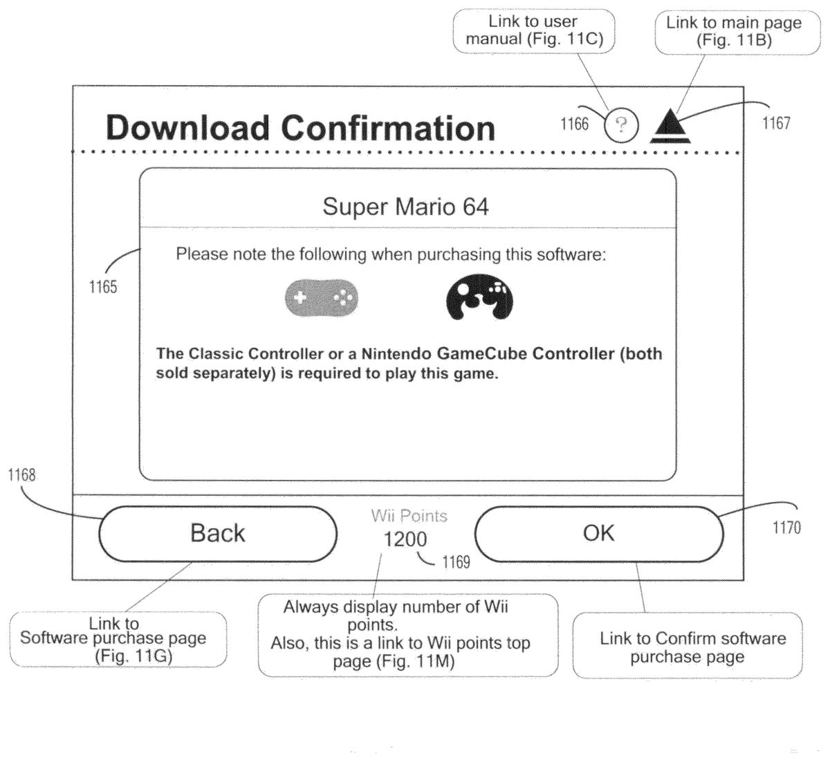
If the parental settings are off, the process proceeds to ST1028. At ST1028, a “caution” screen is displayed. A non-limiting example of a “caution” screen is shown inFIG. 11J.
If the parental settings are on, the process proceeds to ST1024. At ST1024, the user is prompted to enter a parental PIN number. The process determines at ST1025whether the entered parental PIN number is correct. The correctness of the entered PIN number may be determined, for example, by comparing the entered PIN number with a previously entered PIN stored in flash memory332of video game console200. If the entered PIN number is correct, the process proceeds to ST1028at which the “caution” screen is displayed as noted above.
If the entered PIN number is not correct, the process proceeds to ST1026. At ST1026, a screen indicating that an incorrect PIN number has been entered is displayed and the process then proceeds to ST1027where the process determines whether three consecutive PIN entry errors have occurred. If not, the process returns to ST1024and the user can re-enter the PIN number. If so, the process proceeds to ST1061and the main shopping channel screen ofFIG. 11Bis displayed.
The “caution” screen ofFIG. 11Jincludes information1165cautioning the user that a certain type of controller(s) is needed to play the game. If the user does not possess one of the required types of controllers, the user may decide to end the download process. The “caution” screen also includes a link1166for bringing the user to a help screen; a link1167for bringing the user back to the shopping channel main page ofFIG. 11B; a “back” link1168for bringing the user back to the previous page (e.g., the purchase screen ofFIG. 11G); a points indicator/link1169; and an “ok” link1170for bringing the user to a “confirm purchase” screen. The “ok” link is selected if the user wishes to continue the video game program purchase process.
If the user selects the “ok” link from the screen ofFIG. 11Jat ST1028, the process proceeds to ST1029. At ST1029, a “confirm purchase” screen is displayed. A non-limiting example of a “confirm purchase” screen is shown inFIG. 11K. The “confirm purchase” screen ofFIG. 11Kincludes information1171such as a user's current number of points, the number of points required for the download and the number of points that will remain after the download. Information1171may also show the number of open blocks in the flash memory332of the user's console, the number of blocks contained in the downloaded video game program and the number of blocks that will remain in the flash memory after the download. If the user wishes to download the video game program after reviewing this information, “yes” link1174is selected. If the user wishes to terminate the downloading process, “no” link1176is selected. The “confirm purchase” screen also includes a link1172for bringing the user to a help screen; a link1173for bringing the user back to the shopping channel main page ofFIG. 11B, and a points indicator/link1175.
If the user selects the “no” link1176from the “confirm purchase” screen at ST1029, the process returns to ST1019.
If the user selects the “yes” link1174from the “confirm purchase” screen at ST1029, the process proceeds to ST1030. At ST1030, a “receiving software” screen is displayed. A non-limiting example of a “receiving software” screen is shown inFIG. 11L. The “receiving software” screen is displayed while the selected video game and its corresponding emulator are being downloaded and includes information1177indicating the name of the game being downloaded, the number of points the user will have after the download and the number of free flash memory blocks the console will have after the download. A graphic download progress indicator1178may be used to indicate the progress of the download. The “receiving software” screen also includes a points indicator1179. In this example process, points indicator1179does not function as a link to some other display screen.
After the receiving at ST1030, the process determines at ST1031whether the program was received successfully. If not, the process proceeds to ST1032where a receiving error screen is displayed. The receiving error screen informs that user that there was an error downloading the video game program and provides the user an opportunity to try again to download the game. If the user opts to try another download, the process returns to ST1030. If this download is not successful as determined at ST1031, the error screen is displayed after which the process proceeds to ST1061and the display of the main shopping channel page shown inFIG. 11B. The error screen may include, for example, information (e.g., website, telephone number) for assistance along with an error number for the particular error that occurred during the download. This error number can be used when the website is visited or the telephone number called to identify the error and its possible solutions.
If the process determines at ST1031that the game is successfully downloaded, the process proceeds to ST1033and a “receiving successful” screen is displayed. After reviewing the contents of the “receiving successful” screen, the user can select a link on the screen (e.g., an “ok” link) and the process then proceeds to ST1034. At ST1034, the process determines whether software other than a video game has been downloaded. If so, the process proceeds to ST1061. If not (i.e., a video game has been downloaded), a health and safety screen is displayed at ST1035. After reviewing the health and safety screen, the user may actuate a specified button on controller207and the process then proceeds to ST1061.
At ST1016, the user may select link1105and the process proceeds to ST1036. At ST1036, a top screen for downloading software developed for console200is displayed. From this top screen, the user may access other screens (not shown) for downloading the software.
At ST1016, the user may select link1106to add “points” to the user's account and the process then proceeds to ST1037. At ST1037, an “add points” screen is displayed. A non-limiting example “add points” screen is shown inFIG. 11M. The “add points” screen includes information1180about points and shows an image of a pre-paid card of 1000 points. The user may add points by selecting link1183to redeem a pre-paid points card or by selecting link1184to buy points using a credit card. The “add points” screen also include a link1181for bringing the user to a help screen; a link1182for bringing the user back to the shopping channel main page ofFIG. 11B; a “back” link1185for bringing the user back to the previous page (i.e., the main shopping channel screen ofFIG. 11B); and a points indicator1186. In this example process, points indicator1186does not function as a link to any other display screen.
If the user selects link1183for redeeming a pre-paid points card at ST1037, the process proceeds to ST1052. At ST1052, a “card number input” screen is displayed. A non-limiting example “card number input” screen is shown inFIG. 11N. The screen provides information1187about how to find a card activation number. In one example implementation, the activation number is found by scratching off material from the back of the card to reveal the number. The screen also includes an area for inputting the activation number. If the user positions a cursor on the input area and “clicks” on the area, a software keyboard appears for the user's use in inputting the number. After inputting the activation number, the user can select link1192to continue the redemption process. The “card number input” screen also includes a link1190that can be selected by the user to quit the redemption process; a link1188for bringing the user to a help screen; a link1189for bringing the user back to the shopping channel main page ofFIG. 11B; and a points indicator1191.
After inputting the activation number at ST1052, the process determines at ST1053whether redeeming the card will result in the user's account containing more than a specified maximum number of points. If so, the process proceeds to ST1054and the user is informed by a display screen that the card cannot be redeemed and the process returns to ST1052. If redeeming the card will not cause the user's account to exceed the specified maximum number of points, the process determines at ST1055whether the input activation number is correct. If the entered number is not correct, the process proceeds to ST1056and the user is informed by a display screen that the entered activation number is incorrect. The user can select a “try again” link and the process will then return to ST1052. If the entered activation number is correct, the process proceeds to ST1057and a “confirm redemption” screen is displayed. A non-limiting example “confirm redemption” screen is shown inFIG. 11O. The screen includes but is not limited to information1193indicating the number of points on the card being redeemed. The user can redeem the card by selecting “redeem” link1198and the user choose not to redeem the card by selecting “do not redeem” link1196. The “confirm redemption” screen also includes a link1194for bringing the user to a help screen; a link1195for bringing the user back to the shopping channel main page ofFIG. 11B; and a points indicator1197.
If the user selects the “redeem” link1198, the process continues to ST1050and a screen is provided confirming the user's point balance. From this screen, the user may select to generate a purchase statement (receipt) in which case the process proceeds to ST1049. After generating the receipt, the user may return to the balance confirming screen and thereafter the process continues to ST1061.
If the user selects the “do not redeem” link1196from the “confirm redemption” screen ofFIG. 11O, the process returns to ST1052where the user is prompted to input an activation code.
Various types of pre-paid cards may be used. By way of example, cards may be game-specific and allow a user only to purchase a specific video game program. By way of further example, cards may be platform-specific and allow a user to purchase video game programs for a particular platform (e.g., the NES platform). By way of still further example, cards may be character-based and allow a user to purchase video game programs featuring a certain character. By way of still further example, cards may be game-series-based and allow a user to purchase video game program from a particular series of video games.
If the user chooses the credit card option at ST1037, the process proceeds to ST1038and a “points selection” screen is displayed. A non-limiting example “points selection” screen is shown inFIG. 11P. As shown inFIG. 11P, the screen includes options generally indicated at1199allowing the user to select to purchase 1000, 2000, 3000 or 5000 points. The points indicator1203shows the current number of points in the user's account. Certain ones of the points options may be not be selectable by the user if the purchase of these points would cause the user's account to exceed some maximum number of points (e.g., 20000 points). In the example screen ofFIG. 11P, the user has 15200 points in his or her account. Because the purchase of 5000 points would cause the user's account to exceed the maximum allowable number of points (i.e., 20000 points), the user may not select the 5000 point option. This option may be “grayed out” or simply not displayed. The screen also includes a link1200for bringing the user to a help screen; a link1201for bringing the user back to the shopping channel main page ofFIG. 11B; and a “back” link1202for bringing the user back to the previous page.
After the user selects one of the points options from the screen ofFIG. 11P, the process proceeds to ST1039where the user is prompted to select a particular credit card. After the user makes the credit card selection at ST1039, the process proceeds to ST1040where the user is prompted to enter credit card information (e.g., credit card number, expiration date and security code) for the selected credit card. At ST1040, the user can select a link to obtain more information about the security code (e.g., what it is, where to find it on the credit card, how the security code is used, etc.) and the process proceeds to ST1041where such security code information is displayed. After viewing the security code information, the user can select a “back” link to return to the credit card information entry screen. At ST1040, the user can also select a link to obtain more information about credit card security (e.g., how credit card information is used, the details of the encryption of credit card information, how personal information is stored and used, etc.). After viewing the security information, the user can select a “back” link to return to the credit card information entry screen.
After entering credit card information at ST1040, the user selects a link to continue and the process continues to ST1043and the process determines whether an address input is required. This determination may be based, for example, on the country setting. If address input is required, the process proceeds to ST1044and the user is presented with a credit card address input screen for inputting the billing address of the credit card. After the user inputs this information, the process proceeds to ST1045. If no address input is required, the process proceeds directly to ST1045and the user does not have to enter any billing address information.
At ST1045, the process determines whether the input credit card information is correct. If not, the process proceeds to ST1046and an error screen is displayed. The error screen informs the user that incorrect credit card information has been entered. The screen may further inform the user of the nature of the incorrect entry(ies). For example, the screen may indicate that the credit card has expired, that the entered billing address information is incorrect, etc. After reviewing the error screen at ST1046, the user may select a link to return to the credit card select screen at ST1039.
If the process determines that the input credit card information is correct at ST1045, the process proceeds to ST1047and a “purchase confirmation” screen is displayed. The “purchase confirmation” screen asks the user to confirm the purchase of the points using the credit card and may include information such as the total amount of money charged to the credit card, the total number of points being purchased, any applicable taxes, and restrictions on the use of the points (e.g., they have no monetary value and cannot be redeemed for cash; the points are usable only on the user's console; the money paid for the points is non-refundable and the points are non-transferable; etc.).
If the user does not wish to complete the purchase of points and selects a “no” link at ST1047, the process returns to the purchase point selection screen at ST1038(FIG. 11P). If the user selects a “yes” link at ST1047to complete the point purchase, the process proceeds to ST1048where processing authentication is performed. The user may be presented with a screen asking the user to wait while the credit card is authorized. If the credit card is authorized at ST1048, the process proceeds to ST1050. If there is an error in the credit card authorization, the process proceeds to ST1049and the user is informed of the nature of the error. After viewing the error screen, the user may return to ST1038where the point selection screen is displayed.
At ST1016, the user may select link1107to view a record of account activity. Specifically, if the user selects link1107, the process proceeds to ST1058and a usage record screen is displayed. A non-limiting example usage record screen is shown inFIG. 11Q. The screen ofFIG. 11Qshows a table of events in which each event has an associated date, event type, content associated with the event, points cost of the event and points balance after the event. If the user selects one of the events, the process proceeds to ST1059and a purchase statement screen showing additional information associated with the selected event is displayed. The user may select a “back” link from the purchase statement screen to return to the usage record screen ofFIG. 11P. The usage record screen also includes a link1205for bringing the user to a help screen; a link1206for bringing the user back to the shopping channel main page ofFIG. 11B, a “back” link1207for bringing the user back to the previous page; and points indicator/link108. Left and right arrows1209aand1209bmay be used to move the different pages of the usage record.
In the above-described systems and method, a video game program can be downloaded from server108to a target video game platform (e.g., video game system102). A processing system of server108receives a download request from the target video game platform requesting downloading of a video game program that executes on a native video game platform different than the target video game platform. The target video game platform may provide an interface that allows a user to search for and select a particular video game program for download. The download request is generated in response to the selection of the particular video game program. In response to the download request, server108sends the requested video game program to the target video game platform along with a program for providing compatibility between the target and native video game platforms. The program for compatibility may, for example, be an emulator.
Generally speaking, the systems, methods, and techniques described herein may be implemented in digital electronic circuitry, computer hardware, firmware, software, or in combinations of these elements. Apparatus embodying these techniques may include appropriate input and output devices, a computer processor, and a computer program product tangibly embodied in a machine-readable storage device for execution by a programmable processor. A process embodying these techniques may be performed by a programmable processor executing a program or script of instructions to perform desired functions by operating on input data and generating appropriate output. The techniques may be implemented in one or more computer programs or scripts that are executable on a programmable system including at least one programmable processor coupled to receive data and instructions from, and to transmit data and instructions to, a data storage system, at least one input device, and at least one output device. Suitable processors include, by way of example, both general and special purpose microprocessors. Generally, a processor will receive instructions and data from a read-only memory and/or a random access memory. Storage devices suitable for tangibly embodying computer program instructions and data include all forms of volatile and non-volatile memory, including by way of example semiconductor memory devices, such as Erasable Programmable Read-Only Memory (EPROM), Electrically Erasable Programmable Read-Only Memory (EEPROM), and flash memory devices; magnetic disks such as internal hard disks and removable disks; magneto-optical disks; and Compact Disc Read-Only Memory (CD-ROM). Any of the foregoing may be supplemented by, or incorporated in, specially-designed ASICs (application-specific integrated circuits). The computer program instructions or scripts may also be provided as data signals embodied in a carrier wave or other propagation medium via a communication link (e.g., a modem or wired or wireless network connection).
The above systems and methods are described by way of example and the appended claims are not intended to limited to these examples, but are intended to cover systems and methods including various modifications and equivalent arrangements.
Claims
- A video game program download apparatus configured to download a video game program to a target video game platform, the apparatus comprising at least one processor, the apparatus configured to: generate a user interface for display on the target video game platform, the user interface displaying at least a list of one or more video game programs and, for each program in the list, a corresponding native video game platform and one or more input devices usable with video game program;and receive a download request from the target video game platform requesting downloading of a video game program that executes on a native video game platform different than the target video game platform and, in response thereto, send the requested video game program along with a program for providing compatibility between the target platform and the native video game platform.
- The video game program download apparatus according to claim 1 , wherein the program for providing compatibility comprises an emulator program.
- The video game program download apparatus according to claim 1 , wherein the apparatus comprises part of a server connected to the internet.
- The video game program download apparatus according to claim 1 , wherein the apparatus is further configured to display a warning indicating that at least one specific type of input device is required to play the respective video game.
- The video game program download apparatus according to claim 1 , wherein the user interface further displaying information related to a rating of a corresponding game in the list of one or more video game programs.
- A video game program download method implemented in an information processing apparatus having one or more processors, the method comprising: generating, via the one or more processors, a user interface configured to display on a target video game platform, the user interface displaying at least a list of one or more video game programs and, for each program in the list, a corresponding native video game platform and one or more input devices usable with the video game program;receiving a download request from a target video game platform requesting downloading of a video game program that executes on a native video game platform different than the target video game platform;and in response to the received request, sending the video game program for the requested game along with a program for providing compatibility between the target platform and the native video game platform.
- The video game program download method according to claim 6 , wherein the program for providing compatibility comprises an emulator program.
- A non-transitory computer-readable medium having computer readable code embodied therein for use in the execution in a computer of a method according to claim 6 .
- The video game program download method according to claim 6 , wherein a warning is displayed indicating that at least one specific type of input device is required to play the respective video game.
- A target video game system comprising: an input device;and a processing system configured to: display information for selecting a video game program and, for each video game program, display at least one native video game system corresponding to the associated video game program and display information about one or more input devices usable with the video game program, contact a remotely located video game source and receive therefrom, in response to a video game program selection on a user interface made using the input device of the target video game system, a video game program that executes on a native video game system different than the target video game system along with a program for providing compatibility between the target video game system and the native video game system, and execute the received video game program and the program for providing compatibility.
- The target video game system according to claim 10 , wherein the program for providing compatibility comprises an emulator program.
- The target video game system according to claim 10 , wherein the video game source is contacted over the internet.
- The target video game system according to claim 10 , embodied as a hand-held video game system.
- The target video game system according to claim 10 , embodied as a video game console including audio and video outputs supplied to a television.
- The target video game system according to claim 10 , wherein the processing system is further configured to display a warning indicating that at least one specific type of input device is required to play the respective video game.
- A video game program download method implemented in an information processing apparatus having one or more processors, the method comprising: generating for display, via the one or more processors, information for selecting a video game program and, for each video game program, generating for display a corresponding native video game platform and one or more input devices usable with the video game program;contacting a remotely located video game source;receiving from the video game source in response to a video game program selection a video game program that executes on a native video game platform different than the target video game platform along with a program for providing compatibility between the target video game platform and the native video game platform;and executing the downloaded video game program and the program for providing compatibility.
- The video game program download method according to claim 16 , wherein the program for providing compatibility comprises an emulator program.
- A non-transitory computer-readable medium having computer readable code embodied therein for use in the execution in a computer of a method according to claim 16 .
- The video game program download method according to claim 16 , wherein a warning is displayed indicating that at least one specific type of input device is required to play the respective video game.
- An internet-enabled video game system comprising: an input device;an optical disk drive configured to receive an optical disk on which is stored a video game program;and a video game program executing system configured to directly execute the video game program stored on the optical disk, the video game program executing system configured to: generate for display a list of one or more video game programs and, for each program in the list, a corresponding native video game platform and one or more input devices usable with the video game program;and access a source of video game programs associated with the one or more native video game platforms and which are not directly executable by the video game program executing system and, in response to a video game selection on the user interface made using the input device, receive both a selected one of the video game programs that is not directly executable by the video game program executing system and an emulator program for enabling the video game program executing system to emulate a video game program executing system on which the selected video game is directly executable.
- The internet-enabled video game system according to claim 20 , wherein the video game program executing system is further configured to display a warning indicating that at least one specific type of input device is required to play the respective video game.
Disclaimer: Data collected from the USPTO and may be malformed, incomplete, and/or otherwise inaccurate.