U.S. Pat. No. 8,976,265
APPARATUS FOR IMAGE AND SOUND CAPTURE IN A GAME ENVIRONMENT
AssigneeSony Interactive Entertainment Inc
Issue DateOctober 26, 2011
Illustrative Figure
Abstract
An apparatus for capturing image and sound during interactivity with a computer game in a game environment is provided. The apparatus includes a housing and a base stand for supporting the housing. An image capture device is defined along a front portion of the housing. Also, an array of microphones is defined along the front portion of the housing. The array of microphones is defined by a single microphone positioned on a first lateral side of the image capture device and two or more microphones positioned on a second lateral side of the image capture device opposite the first side. The apparatus also includes a connector for connecting to a computing device.
Description
DETAILED DESCRIPTION An invention is disclosed for methods and apparatus for facilitating the identification of specific sound sources and filtering out unwanted sound sources when sound is used as an interactive tool with a computer program. In the following description, numerous specific details are set forth in order to provide a thorough understanding of the present invention. It will be apparent, however, to one skilled in the art that the present invention may be practiced without some or all of these specific details. In other instances, well known process steps have not been described in detail in order not to obscure the present invention. FIG. 1shows a game environment100in which a video game program may be executed for interactivity with one or more users, in accordance with one embodiment of the present invention. As illustrated, player102is shown in front of a monitor108that includes a display110. The monitor108is interconnected with a computing system104. The computing system can be a standard computer system, a game console or a portable computer system. In a specific example, but not limited to any brand, the game console can be a one manufactured by Sony Computer Entertainment Inc., Microsoft, or any other manufacturer. Computing system104is shown interconnected with an image-sound capture device106. The image-sound capture device106includes a sound capture unit106aand an image capture unit106b. The player102is shown interactively communicating with a gameFIG. 112on the display110. The video game being executed is one in which input is at least partially provided by the player102by way of the image capture unit106b, and the sound capture unit106a. As illustrated, the player102may move his hand so as to select interactive icons114on the display110. A translucent image of the player102′ is projected on the display110once captured by the image capture unit106b. Thus, the player102knows where to move his hand in order ...
DETAILED DESCRIPTION
An invention is disclosed for methods and apparatus for facilitating the identification of specific sound sources and filtering out unwanted sound sources when sound is used as an interactive tool with a computer program.
In the following description, numerous specific details are set forth in order to provide a thorough understanding of the present invention. It will be apparent, however, to one skilled in the art that the present invention may be practiced without some or all of these specific details. In other instances, well known process steps have not been described in detail in order not to obscure the present invention.
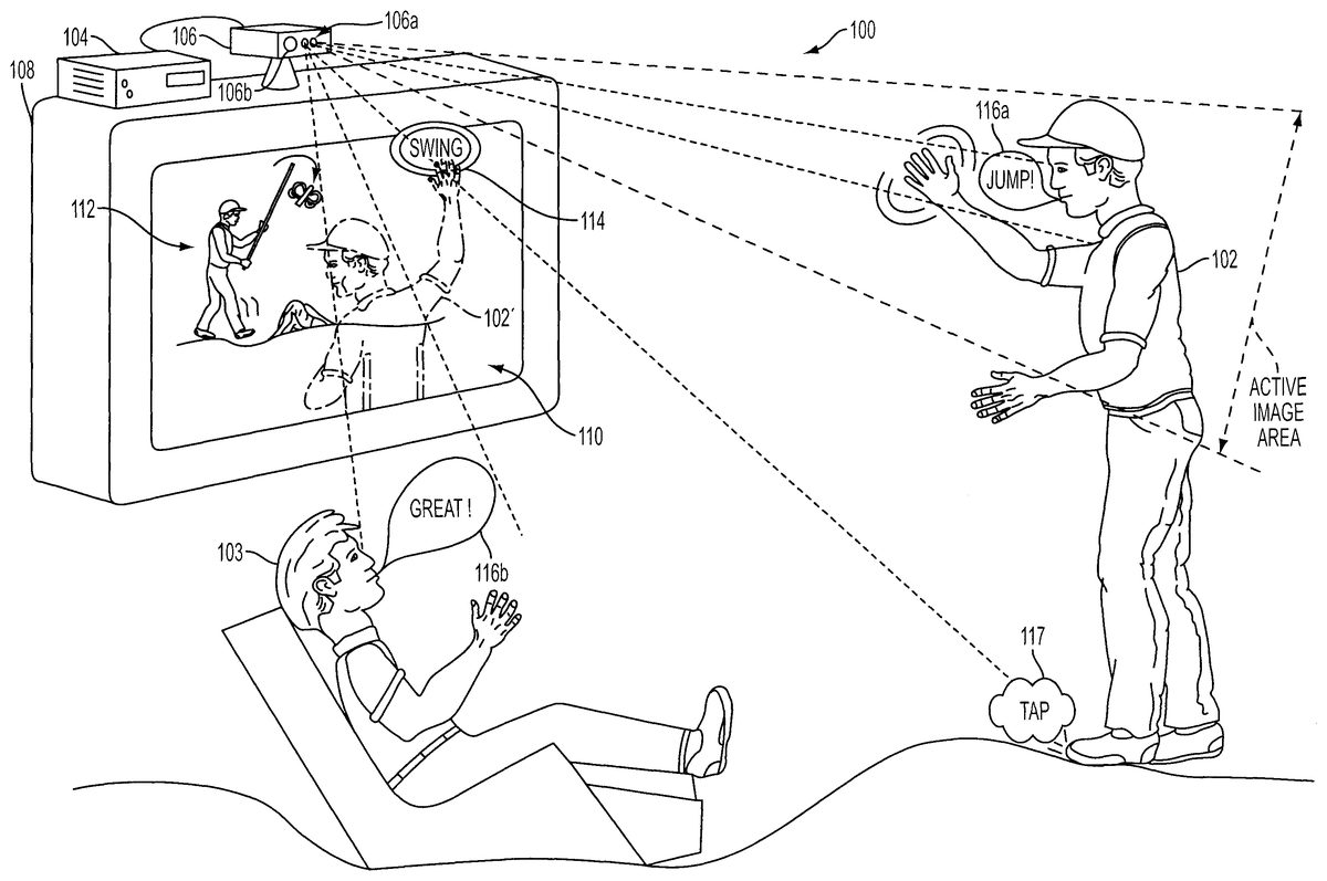
FIG. 1shows a game environment100in which a video game program may be executed for interactivity with one or more users, in accordance with one embodiment of the present invention. As illustrated, player102is shown in front of a monitor108that includes a display110. The monitor108is interconnected with a computing system104. The computing system can be a standard computer system, a game console or a portable computer system. In a specific example, but not limited to any brand, the game console can be a one manufactured by Sony Computer Entertainment Inc., Microsoft, or any other manufacturer.
Computing system104is shown interconnected with an image-sound capture device106. The image-sound capture device106includes a sound capture unit106aand an image capture unit106b. The player102is shown interactively communicating with a gameFIG. 112on the display110. The video game being executed is one in which input is at least partially provided by the player102by way of the image capture unit106b, and the sound capture unit106a. As illustrated, the player102may move his hand so as to select interactive icons114on the display110. A translucent image of the player102′ is projected on the display110once captured by the image capture unit106b. Thus, the player102knows where to move his hand in order to cause selection of icons or interfacing with the gameFIG. 112. Techniques for capturing these movements and interactions can vary, but exemplary techniques are described in United Kingdom Applications GB 0304024.3 (PCT/GB2004/000693) and GB 0304022.7 (PCT/GB2004/000703), each filed on Feb. 21, 2003, and each of which is hereby incorporated by reference.
In the example shown, the interactive icon114is an icon that would allow the player to select “swing” so that the gameFIG. 112will swing the object being handled. In addition, the player102may provide voice commands that can be captured by the sound capture unit106aand then processed by the computing system104to provide interactivity with the video game being executed. As shown, the sound source116ais a voice command to “jump!”. The sound source116awill then be captured by the sound capture unit106a, and processed by the computing system104to then cause the gameFIG. 112to jump. Voice recognition may be used to enable the identification of the voice commands. Alternatively, the player102may be in communication with remote users connected to the internet or network, but who are also directly or partially involved in the interactivity of the game.
In accordance with one embodiment of the present invention, the sound capture unit106ais configured to include at least two microphones which will enable the computing system104to select sound coming from particular directions. By enabling the computing system104to filter out directions which are not central to the game play (or the focus), distracting sounds in the game environment100will not interfere with or confuse the game execution when specific commands are being provided by the player102. For example, the game player102may be tapping his feet and causing a tap noise which is a non-language sound117. Such sound may be captured by the sound capture unit106a, but then filtered out, as sound coming from the player's feet102is not in the zone of focus for the video game.
As will be described below, the zone of focus is preferably identified by the active image area that is the focus point of the image capture unit106b. In an alternative manner, the zone of focus can be manually selected from a choice of zones presented to the user after an initialization stage. Continuing with the example ofFIG. 1, a game observer103may be providing a sound source116bwhich could be distracting to the processing by the computing system during the interactive game play. However, the game observer103is not in the active image area of the image capture unit106band thus, sounds coming from the direction of game observer103will be filtered out so that the computing system104will not erroneously confuse commands from the sound source116bwith the sound sources coming from the player102, as sound source116a.
The image-sound capture device106includes an image capture unit106b, and the sound capture unit106a. The image-sound capture device106is preferably capable of digitally capturing image frames and then transferring those image frames to the computing system104for further processing. An example of the image capture unit106bis a web camera, which is commonly used when video images are desired to be captured and then transferred digitally to a computing device for subsequent storage or communication over a network, such as the internet. Other types of image capture devices may also work, whether analog or digital, so long as the image data is digitally processed to enable the identification and filtering. In one preferred embodiment, the digital processing to enable the filtering is done in software, after the input data is received. The sound capture unit106ais shown including a pair of microphones (MIC1and MIC2). The microphones are standard microphones, which can be integrated into the housing that makes up the image-sound capture device106.
FIG. 3Aillustrates sound capture units106awhen confronted with sound sources116from sound A and sound B. As shown, sound A will project its audible sound and will be detected by MIC1and MIC2along sound paths201aand201b. Sound B will be projected toward MIC1and MIC2over sound paths202aand202b. As illustrated, the sound paths for sound A will be of different lengths, thus providing for a relative delay when compared to sound paths202aand202b. The sound coming from each of sound A and sound B will then be processed using a standard triangulation algorithm so that direction selection can occur in box216, shown inFIG. 3B. The sound coming from MIC1and MIC2will each be buffered in buffers1and2(210a,210b), and passed through delay lines (212a,212b). In one embodiment, the buffering and delay process will be controlled by software, although hardware can be custom designed to handle the operations as well. Based on the triangulation, direction selection216will trigger identification and selection of one of the sound sources116.
The sound coming from each of MICs1and MICs2will be summed in box214before being output as the output of the selected source. In this manner, sound coming from directions other than the direction in the active image area will be filtered out so that such sound sources do not distract processing by the computer system104, or distract communication with other users that may be interactively playing a video game over a network, or the internet.
FIG. 4illustrates a computing system250that may be used in conjunction with the image-sound capture device106, in accordance with one embodiment of the present invention. The computing system250includes a processor252, and memory256. A bus254will interconnect the processor and the memory256with the image-sound capture device106. The memory256will include at least part of the interactive program258, and also include selective sound source listening logic or code260for processing the received sound source data. Based on where the zone of focus is identified to be by the image capture unit106b, sound sources outside of the zone of focus will be selectively filtered by the selective sound source listening logic260being executed (e.g., by the processor and stored at least partially in the memory256). The computing system is shown in its most simplistic form, but emphasis is placed on the fact that any hardware configuration can be used, so long as the hardware can process the instructions to effect the processing of the incoming sound sources and thus enable the selective listening.
The computing system250is also shown interconnected with the display110by way of the bus. In this example, the zone of focus is identified by the image capture unit being focused toward the sound source B. Sound coming from other sound sources, such as sound source A will be substantially filtered out by the selective sound source listening logic260when the sound is captured by the sound capture unit106aand transferred to the computing system250.
In one specific example, a player can be participating in an internet or networked video game competition with another user where each user's primary audible experience will be by way of speakers. The speakers may be part of the computing system or may be part of the monitor108. Suppose, therefore, that the local speakers are what is generating sound source A as shown inFIG. 4. In order not to feedback the sound coming out of the local speakers for sound source A to the competing user, the selective sound source listening logic260will filter out the sound of sound source A so that the competing user will not be provided with feedback of his or her own sound or voice. By supplying this filtering, it is possible to have interactive communication over a network while interfacing with a video game, while advantageously avoiding destructive feedback during the process.
FIG. 5illustrates an example where the image-sound capture device106includes at least four microphones (MIC1through MIC4). The sound capture unit106a, is therefore capable of triangulation with better granularity to identify the location of sound sources116(A and B). That is, by providing an additional microphone, it is possible to more accurately define the location of the sound sources and thus, eliminate and filter out sound sources that are not of interest or can be destructive to game play or interactivity with a computing system. As illustrated inFIG. 5, sound source116(B) is the sound source of interest as identified by the video capture unit106b. Continuing with example ofFIG. 5,FIG. 6identifies how sound source B is identified to a spatial volume.
The spatial volume at which sound source B is located will define the volume of focus274. By identifying a volume of focus, it is possible to eliminate or filter out noises that are not within a specific volume (i.e., which are not just in a direction). To facilitate the selection of a volume of focus274, the image-sound capture device106will preferably include at least four microphones. At least one of the microphones will be in a different plane than three of the microphones. By maintaining one of the microphones in plane271and the remainder of the four in plane270of the image-sound capture device106, it is possible to define a spatial volume.
Consequently, noise coming from other people in the vicinity (shown as276aand276b) will be filtered out as they do not lie within the spatial volume defined in the volume focus274. Additionally, noise that may be created just outside of the spatial volume, as shown by speaker276c, will also be filtered out as it falls outside of the spatial volume.
FIG. 7illustrates a flowchart diagram in accordance with one embodiment of the present invention. The method begins at operation302where input is received from one or more sound sources at two or more sound capture microphones. In one example, the two or more sound capture microphones are integrated into the image-sound capture device106. Alternatively, the two or more sound capture microphones can be part of a second module/housing that interfaces with the image capture unit106b. Alternatively, the sound capture unit106acan include any number of sound capture microphones, and sound capture microphones can be placed in specific locations designed to capture sound from a user that may be interfacing with a computing system.
The method moves to operation304where a delay path for each of the sound sources is determined. Example delay paths are defined by the sound paths201and202ofFIG. 3A. As is well known, the delay paths define the time it takes for sound waves to travel from the sound sources to the specific microphones that are situated to capture the sound. Based on the delay it takes sound to travel from the particular sound sources116, the microphones can determine what the delay is and approximate location from which the sound is emanating from using a standard triangulation algorithm.
The method then continues to operation306where a direction for each of the received inputs of the one or more sound sources is identified. That is, the direction from which the sound is originating from the sound sources116is identified relative to the location of the image-sound capture device, including the sound capture unit106a. Based on the identified directions, sound sources that are not in an identified direction of a zone (or volume) of focus are filtered out in operation308. By filtering out the sound sources that are not originating from directions that are in the vicinity of the zone of focus, it is possible to use the sound source not filtered out for interactivity with a computer program, as shown in operation310.
For instance, the interactive program can be a video game in which the user can interactively communicate with features of the video game, or players that may be opposing the primary player of the video game. The opposing player can either be local or located at a remote location and be in communication with the primary user over a network, such as the internet. In addition, the video game can also be played between a number of users in a group designed to interactively challenge each other's skills in a particular contest associated with the video game.
FIG. 8illustrates a flowchart diagram in which image-sound capture device operations320are illustrated separate from the software executed operations that are performed on the received input in operations340. Thus, once the input from the one or more sound sources at the two or more sound capture microphones is received in operation302, the method proceeds to operation304where in software, the delay path for each of the sound sources is determined. Based on the delay paths, a direction for each of the received inputs is identified for each of the one or more sound sources in operation306, as mentioned above.
At this point, the method moves to operation312where the identified direction that is in proximity of video capture is determined. For instance, video capture will be targeted at an active image area as shown inFIG. 1. Thus, the proximity of video capture would be within this active image area (or volume), and any direction associated with a sound source that is within this or in proximity to this, image-active area, will be determined. Based on this determination, the method proceeds to operation314where directions (or volumes) that are not in proximity of video capture are filtered out. Accordingly, distractions, noises and other extraneous input that could interfere in video game play of the primary player will be filtered out in the processing that is performed by the software executed during game play.
Consequently, the primary user can interact with the video game, interact with other users of the video game that are actively using the video game, or communicate with other users over the network that may be logged into or associated with transactions for the same video game that is of interest. Such video game communication, interactivity and control will thus be uninterrupted by extraneous noises and/or observers that are not intended to be interactively communicating or participating in a particular game or interactive program.
It should be appreciated that the embodiments described herein may also apply to on-line gaming applications. That is, the embodiments described above may occur at a server that sends a video signal to multiple users over a distributed network, such as the Internet, to enable players at remote noisy locations to communicate with each other. It should be further appreciated that the embodiments described herein may be implemented through either a hardware or a software implementation. That is, the functional descriptions discussed above may be synthesized to define a microchip having logic configured to perform the functional tasks for each of the modules associated with the noise cancellation scheme.
Also, the selective filtering of sound sources can have other applications, such as telephones. In phone use environments, there is usually a primary person (i.e., the caller) desiring to have a conversation with a third party (i.e., the callee). During that communication, however, there may be other people in the vicinity who are either talking or making noise. The phone, being targeted toward the primary user (by the direction of the receiver, for example) can make the sound coming from the primary user's mouth the zone of focus, and thus enable the selection for listening to only the primary user. This selective listening will therefore enable the substantial filtering out of voices or noises that are not associated with the primary person, and thus, the receiving party will be able to receive a more clear communication from the primary person using the phone.
Additional technologies may also include other electronic equipment that can benefit from taking in sound as an input for control or communication. For instance, a user can control settings in an automobile by voice commands, while avoiding other passengers from disrupting the commands. Other applications may include computer controls of applications, such as browsing applications, document preparation, or communications. By enabling this filtering, it is possible to more effectively issue voice or sound commands without interruption by surrounding sounds. As such, any electronic apparatus.
Further, the embodiments of the present invention have a wide array of applications, and the scope of the claims should be read to include any such application that can benefit from the such embodiments.
For instance, in a similar application, it may be possible to filter out sound sources using sound analysis. If sound analysis is used, it is possible to use as few as one microphone. The sound captured by the single microphone can be digitally analyzed (in software or hardware) to determine which voice or sound is of interest. In some environments, such as gaming, it may be possible for the primary user to record his or her voice once to train the system to identify the particular voice. In this manner, exclusion of other voices or sounds will be facilitated. Consequently, it would not be necessary to identify a direction, as filtering could be done based one sound tones and/or frequencies.
All of the advantages mentioned above with respect to sound filtering, when direction and volume are taken into account, are equally applicable.
With the above embodiments in mind, it should be understood that the invention may employ various computer-implemented operations involving data stored in computer systems. These operations include operations requiring physical manipulation of physical quantities. Usually, though not necessarily, these quantities take the form of electrical or magnetic signals capable of being stored, transferred, combined, compared, and otherwise manipulated. Further, the manipulations performed are often referred to in terms, such as producing, identifying, determining, or comparing.
The above described invention may be practiced with other computer system configurations including hand-held devices, microprocessor systems, microprocessor-based or programmable consumer electronics, minicomputers, mainframe computers and the like. The invention may also be practiced in distributing computing environments where tasks are performed by remote processing devices that are linked through a communications network.
The invention can also be embodied as computer readable code on a computer readable medium. The computer readable medium is any data storage device that can store data which can be thereafter read by a computer system, including an electromagnetic wave carrier. Examples of the computer readable medium include hard drives, network attached storage (NAS), read-only memory, random-access memory, CD-ROMs, CD-Rs, CD-RWs, magnetic tapes, and other optical and non-optical data storage devices. The computer readable medium can also be distributed over a network coupled computer system so that the computer readable code is stored and executed in a distributed fashion.
Although the foregoing invention has been described in some detail for purposes of clarity of understanding, it will be apparent that certain changes and modifications may be practiced within the scope of the appended claims. Accordingly, the present embodiments are to be considered as illustrative and not restrictive, and the invention is not to be limited to the details given herein, but may be modified within the scope and equivalents of the appended claims.
Claims
- An apparatus for capturing image and sound during interactivity with a computer game in a game environment, comprising: a housing;a base stand for supporting the housing;an image capture device defined along a front portion of the housing;an array of microphones defined along the front portion of the housing, the array of microphones defined by a single microphone positioned on a first lateral side of the image capture device and two or more microphones positioned on a second lateral side of the image capture device opposite the first side;a connector for connecting to a computing device;wherein the microphones of the microphone array are linearly arranged;wherein a distance between the single microphone on the first lateral side and a first one of the microphones on the second lateral side is greater than a distance between the first one of the microphones on the second lateral side and a second one of the microphones on the second lateral side, the first one of the microphones being a nearest microphone to the single microphone and the second one of the microphones being a next nearest microphone to the single microphone.
- The apparatus for capturing image and sound of claim 1 , wherein at least one of the microphones of the microphone array is oriented towards a direction different than a direction towards which the image capture device is oriented.
- The apparatus for capturing image and sound of claim 1 , wherein the array of microphones includes four microphones only.
- The apparatus for capturing image and sound of claim 1 , wherein the image capture device is a depth camera that captures depth values for a plurality of pixels.
- The apparatus for capturing image and sound of claim 4 , further comprising an infrared light for providing controlled infrared lighting;wherein the depth camera uses the controlled infrared lighting to obtain the depth values.
- The apparatus for capturing image and sound of claim 5 , wherein the image capture device defines a maximum depth detection range beyond which depth values are not detected.
- The apparatus for capturing image and sound of claim 6 , further comprising, logic initiating tracking of an object when the object is placed within the depth range and terminating tracking of the object when the object is placed beyond the depth range.
- The apparatus for capturing image and sound of claim 4 , further comprising, logic for mapping depth values of a control object captured by the depth camera to a model, wherein in response to movement of the control object, a position of the model is moved in a corresponding fashion.
- The apparatus for capturing image and sound of claim 1 , wherein the image capture device is an RGB camera that captures RGB values for a plurality of pixels.
- A system for providing interactive gameplay of a video game, comprising for capturing image and sound during interactivity with a computer game in a game environment, comprising: a computing device, the computing device including a processor for executing a video game;an image and sound capture device connected to the computing device, the image and sound capture device including a housing, a base stand for supporting the housing, an image capture device defined along a front portion of the housing, an array of microphones defined along the front portion of the housing, the array of microphones defined by a single microphone positioned on a first lateral side of the image capture device and two or more microphones positioned on a second lateral side of the image capture device opposite the first lateral side;wherein the microphones of the microphone array are linearly arranged;and wherein a distance between the single microphone on the first lateral side and a first one of the microphones on the second lateral side is greater than a distance between the first one of the microphones on the second lateral side and a second one of the microphones on the second lateral side, the first one of the microphones being a nearest microphone to the single microphone and the second one of the microphones being a next nearest microphone to the single microphone.
- The system for providing interactive gameplay of claim 10 , wherein the image capture device is a depth camera that captures depth values for a plurality of pixels.
- The system for providing interactive gameplay of claim 11 , further comprising an infrared light for providing controlled infrared lighting;wherein the depth camera uses the controlled infrared lighting to obtain the depth values.
- The system for providing interactive gameplay of claim 12 , wherein the image capture device defines a maximum depth detection range beyond which depth values are not detected.
- The system for providing interactive gameplay of claim 10 , further comprising logic for mapping depth values of a control object captured by the depth camera to a model, wherein in response to movement of the control object, a position of the model is moved in a corresponding fashion.
- The system for providing interactive gameplay of claim 14 , wherein the model is a skeleton model associated with the control object, the skeleton model defining one or more joint angles.
- The system for providing interactive gameplay of claim 10 , further comprising, logic for associating a movement of a control object captured by the image capture device with a corresponding predefined animation of a character of the video game.
- The system for providing interactive gameplay of claim 10 , further comprising, logic for applying a movement of a control object captured by the image capture device as constraint information to directly drive the animation of a character image.
- The system for providing interactive gameplay of claim 10 , wherein the image capture device is an RGB camera that captures RGB values for a plurality of pixels.
Disclaimer: Data collected from the USPTO and may be malformed, incomplete, and/or otherwise inaccurate.