U.S. Pat. No. 8,972,658
Game console and memory card
AssigneeNintendo Co., Ltd.
Issue DateAugust 14, 2009
Illustrative Figure
Abstract
An example portable, handheld game console includes a main body incorporating a first display screen, and a cover body incorporating a second display screen. The main body is hingedly connected to the cover body along adjacent forward and rearward edges, respectively, such that the cover body is movable between closed and open positions. The main body is provided with a plurality of control buttons and a pair of game card slots for receiving game cards of different dimensions. One of the game cards is substantially square and comprises a substantially flat card body having a plurality of electrically conductive terminal strips adjacent the forward edge. One of the side edges of the card has a single continuous step configuration along substantially the entire length dimension of the card. A first notch is formed in a first forward corner of the card where the forward edge meets the other of the pair of side edges and a second notch is formed along the other of the pair of side edges, between the forward and rearward edges.
Description
DETAILED DESCRIPTION OF EXAMPLE EMBODIMENTS Referring toFIGS. 1 and 2, in an illustrative embodiment the game device or console10includes a main body12and a cover body14hingedly connected to each other along an upper edge of the main body12and a lower edge of the cover body14(references herein to terms such as “upper” and “lower” and “forward” and “rearward” are for ease of understanding and are made relative to an orientation of the game device where the cover body14is in an open position and the game is being held by a user in a normal operating position). Hinge elements16,18and20on the main body12mesh with hinge elements22and24on the cover body, with a hinge pin (not shown) extending through the aligned hinge elements in conventional fashion. Note that because hinge elements16,18and20extend from the upper (or inner) face26of the main body12, the cover body14overlies the upper face26when the cover body14is closed over the main body. When the cover body14is in its fully open position, it is substantially parallel to the main body12but lies in a substantially parallel, offset plane. The main body12also has a lower (or outer) face28(FIG. 2) and a peripheral edge30. A first display screen32is recessed within the upper face26of the main body12with dimensions of approximately 2½ inches in length and 1⅞ inches in width, yielding a diagonal screen dimension of 3 inches. The screen in the exemplary embodiment is a backlit, color liquid crystal display (LCD). This screen is touch sensitive and may be activated by a stylus, described further herein. A power button34is located in the upper left corner of face26and is used to turn the game on and off. A cross-shaped directional control button36is located adjacent and below the power button34, and is used for game play control. In the upper right corner of the main body12, there are side-by-side “start” and ...
DETAILED DESCRIPTION OF EXAMPLE EMBODIMENTS
Referring toFIGS. 1 and 2, in an illustrative embodiment the game device or console10includes a main body12and a cover body14hingedly connected to each other along an upper edge of the main body12and a lower edge of the cover body14(references herein to terms such as “upper” and “lower” and “forward” and “rearward” are for ease of understanding and are made relative to an orientation of the game device where the cover body14is in an open position and the game is being held by a user in a normal operating position). Hinge elements16,18and20on the main body12mesh with hinge elements22and24on the cover body, with a hinge pin (not shown) extending through the aligned hinge elements in conventional fashion. Note that because hinge elements16,18and20extend from the upper (or inner) face26of the main body12, the cover body14overlies the upper face26when the cover body14is closed over the main body. When the cover body14is in its fully open position, it is substantially parallel to the main body12but lies in a substantially parallel, offset plane. The main body12also has a lower (or outer) face28(FIG. 2) and a peripheral edge30.
A first display screen32is recessed within the upper face26of the main body12with dimensions of approximately 2½ inches in length and 1⅞ inches in width, yielding a diagonal screen dimension of 3 inches. The screen in the exemplary embodiment is a backlit, color liquid crystal display (LCD). This screen is touch sensitive and may be activated by a stylus, described further herein. A power button34is located in the upper left corner of face26and is used to turn the game on and off. A cross-shaped directional control button36is located adjacent and below the power button34, and is used for game play control.
In the upper right corner of the main body12, there are side-by-side “start” and “select” buttons38,40, respectively, with X/Y/A/B buttons42located adjacent and below the “start” and select” buttons. Buttons38,40and42are also used for game play control. A microphone44is located below the left edge of screen32for use with specially designed games having a microphone feature. A battery recharge indicator LED46and a power indicator LED48are also located on the upper face26, adjacent the lower edge thereof, below the right edge of screen32.
With reference now especially toFIG. 3, a lower or forward portion50of the peripheral edge30(closest to the user) is provided with a volume control slide52and headphone and microphone connectors54,56on either side of a first game slot58. Slot58is especially designed for larger game cartridges or cards originally designed for use with the assignee's Game Boy Advance® game system.
As best seen inFIG. 2, an upper or rearward portion60of the peripheral edge30is provided with an external extension connector62that permits connection to an AC adapter for recharging the internal battery (not shown), or for operating the game using household power. A second game slot64in edge portion60is designed for receiving memory or game cards especially designed for this game device. The second game slot64is smaller than the first game slot58, reflecting the different sizes of the game cards. Openings66,68form an elbow-shaped through slot adapted for securing a wrist strap (not shown), thereby enabling the user to secure the game device to the body and thus minimize the potential for losing or misplacing the game. A stylus port or holder, in the form of a blind bore70is located adjacent the wrist-strap mount for holding a stylus71(FIG. 5) before or after use.
The stylus71is a plastic pencil-shaped device with a rounded tip73and is used to activate the touch screen32.
A pair of left, right control buttons (or shoulder buttons)72,74are located on the peripheral edge30, at the corners where the upper portion60of the peripheral edge30meets the side portions76,78of the peripheral edge. The location of these buttons and the location of previously described buttons34,36and42facilitate manipulation game control by the user's thumbs and index fingers when the game is held with two hands in a natural and intuitive manner.
The lower (or outer) face28of the main body is provided with a battery cover80(FIG. 2) for accessing a rechargeable battery pack located within the main body.
The cover body14also has an upper (or inner) face82(FIG. 1) and a lower (or outer) face84(FIG. 2) connected by a peripheral edge86. The upper face60incorporates a second display screen88of substantially the same dimensions as screen32. Screen88is also a backlit color LCD. The cover body14also incorporates a pair of stereo speakers, with speaker grills90,92located on opposite sides of the screen88. Dimples or pads94,96may be located above and laterally of screen88. The dimples may be made of a compressible polymer or other suitable material and serve to dampen engagement of the inner surface82of the cover body14with the inner surface26of the main body12when the cover body is closed over the main body.
As already noted, the game card slot58is sized and adapted to receive a conventional game card designed for the by now well known Nintendo Gameboy Advance System®. Accordingly, the game card per se for slot58does not form any part of this invention and need not be described further.
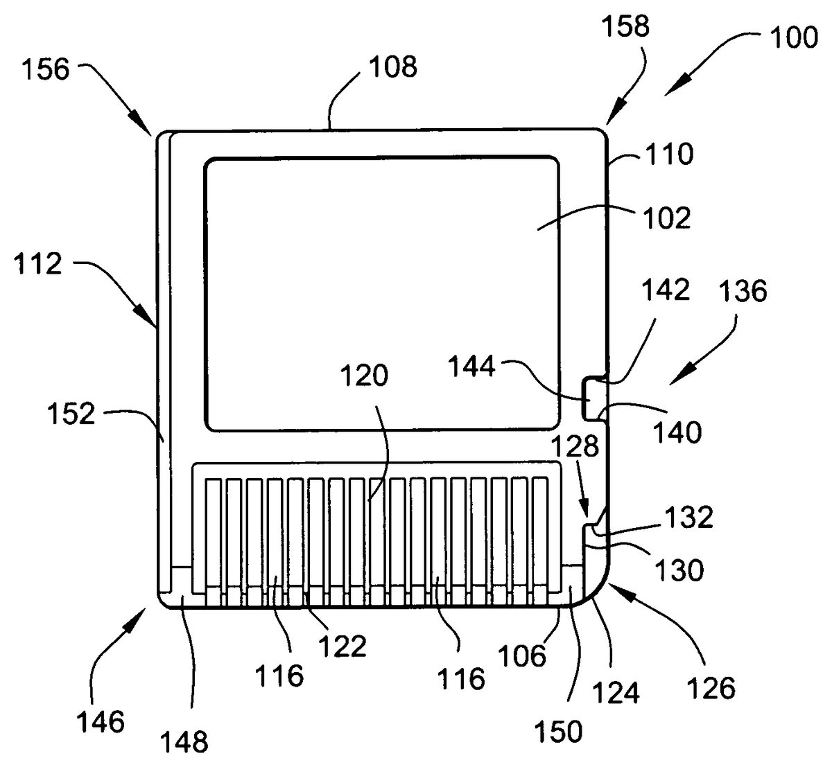
The new game or memory card100designed especially for use with this game device is shown inFIGS. 6,7and8.
The game or memory card100is preferably of molded plastic construction and has substantially planar upper and lower surfaces102,104, respectively, a forward edge106, rearward edge108and side edges110,112. The forward end of the upper surface102is formed with a rectangular recess114in which a plurality of terminal strips116are located, extending from a rear wall118of the recess to the forward edge106of the card. The rearward wall115of the recess is substantially perpendicular to the upper and lower surfaces102,104but, as a practical matter, is sloped by no more than about 3 degrees simply to facilitate removal of the card from the mold during manufacture of the card. The terminal strips116are parallel to each other and are separated by raised ribs120that also extend from the rear wall118to the forward edge106. The free ends122of the ribs120are chamfered as best seen inFIG. 8to facilitate sliding entry of the card into the slot58in the main body12. Ribs120also protect the terminal strips116from contact with the users' hands or other objects. The recess114and array of terminal strips116are not centered along the forward edge106of the card, but rather, are offset laterally toward the side edge112for a purpose explained in greater detail below.
An enlarged radius124is formed at forward corner126where the side edge110meets forward edge106. A first notch128is formed in corner126, defined by a vertical notch side wall130, a vertical notch back wall132and a flat notch bottom wall134. The latter is parallel to the upper and lower card surfaces102,104, while notch side wall130is parallel to side edges110,112, and notch back wall is perpendicular to the notch side wall130and parallel to the card forward edge106. The depth of the notch is about half the approximate ⅛ inch thickness of the card, and the length of the notch is about ¼ inch, which in turn, is about half the length of the recess114. Rearwardly of the notch128, along the card side edge110, there is formed a second notch136that opens to the side of the card, defined by parallel side walls140,142and a back wall144. Side walls140,142are parallel to forward and rearward card edges106,108while back wall144is parallel to card side edges110,112. An angled surface145connects back wall144to the edge110. Here again, the depth of the notch is about half the thickness of the card, and the length of the notch is about ⅛ inch.
Notches128and136cooperate with components of a “push-push” mechanism inside the game slot64to provide controlled, spring-loaded movement of the game card during insertion and ejection.
The opposite forward corner146of the card where side edge112meets forward edge106is defined by a smaller radius than radius124. Note that the forward surfaces148,150of the card on either side of the recess114are also chamfered to substantially the same degree as the chamfer on ribs120.
Side edge112is stepped along its entire length in the upper plane of the card only, as defined by horizontal shoulder152that is parallel to upper and lower surfaces102,104and a recessed edge portion shoulder154that is parallel to the side edges110,112. This shoulder insures correct orientation of the card when inserted into a game console slot.
The rearward edge108of the card is substantially uniform in profile from side edge110to side edge112, with both rearward corners156,158rounded by a radii similar to the radius at corner146.
The dimensions of the card are matched to the game machine entry slot, and in the exemplary embodiment, the card100is substantially square, with a length dimension (front-to-back) of 1⅜″, and a width dimension (side-to-side) of 1¼″.
FIG. 9is a further illustrative embodiment of a portable game machine200. As with the prior embodiment, a further exemplary game machine physically including two display screens with one of the display screens being covered with a touch panel is exemplarily described. In the present embodiment, a game image is displayed on at least the display screen covered with the touch panel. Also, a non-portable video game machine, an arcade game machine, a portable terminal, a cellular phone, or a personal computer may be used as the game machine.
FIG. 9is an external view of the portable game machine200. As shown inFIG. 9, the portable game machine200includes two display screens, that is, a first display screen211aand a second display screen212a. The surface of the second display screen212ais covered with a touch panel213. Also, to the right of the second display screen212a, the game machine includes an A button214a, a B button214b, and an R switch214c, which are operable by the right hand of the player, and a loudspeaker215for producing game music. To the left of the second display screen212a, the game machine includes a cross key214d, a start button214e, a select button214f, and an L switch214g, which are operable by the left hand of the player. Also, the portable game machine200includes a removable stylus216for input to the touch panel213. Furthermore, the portable game machine200has, removably inserted therein, a cartridge217, which is a storage medium having stored therein a game program of the illustrative embodiments. Note that, in the present embodiment, the touch panel213is exemplarily provided as an input unit, but this does not restrict the present invention.
FIG. 10is a block diagram showing the portable game machine200. It should be understood that the hardware/software and operational description which follows is applicable to the illustrative embodiment shown inFIGS. 1-8as well as the illustrative embodiment shown inFIG. 9. As shown inFIG. 10, the portable game machine200includes a CPU (central processing unit)223, which is an example of a computer for executing the game program, and other components. The CPU223includes a work RAM (working storage unit)224, a GPU (graphic processing unit)222, and a peripheral circuit I/F (interface)225that are electrically connected to one another. The work RAM224is a memory for temporarily storing, for example, the game program to be executed by the CPU223and calculation results of the CPU223. The GPU222uses, in response to an instruction from the CPU223, a VRAM221to generate a game image for display output to a first LCD (liquid crystal display unit)211and a second LCD212, and causes the generated game image to be displayed on the first display screen211aof the first LCD211and the second display screen212aof the second LCD212. The peripheral circuit I/F225is a circuit for transmitting and receiving data between external input/output units, such as the touch panel213, the operation keys214, and the loudspeaker215, and the CPU223. The touch panel213(including a device driver for the touch panel) outputs coordinate data corresponding to a position input (specified) with the stylus216.
Furthermore, the CPU223is electrically connected to the external memory I/F226, in which the cartridge217is inserted. The cartridge217is a storage medium for storing the game program and, specifically, includes a program ROM217afor storing the game program and a backup RAM217bfor rewritably storing backup data. The game program stored in the program ROM217aof the cartridge217is loaded to the work RAM224and is then executed by the CPU223. In the present embodiment, an exemplary case is described in which the game program is supplied from an external storage medium to the portable game machine200. However, the game program may be stored in a non-volatile memory incorporated in advance in the portable game machine200, or may be supplied to the portable game machine200via a wired or wireless communication circuit.
FIG. 11is a block diagram of the GPU222. The GPU222includes two image processing units, that is, a three-dimensional image processing unit231and a two-dimensional image processing unit237. The three-dimensional image processing unit231includes a geometry engine for calculating each vertex of a three-dimensional model based on three-dimensional model data and a rendering engine for generating a game image from the three-dimensional model disposed on a virtual three-dimensional game space. The two-dimensional image processing unit237includes a 2D rendering engine for generating a game image based on two-dimensional image data representing characters and two-dimensional image data representing backgrounds. More specifically, the two-dimensional image processing unit237disposes a two-dimensional image representing a character on a virtual screen called a “sprite” and a two-dimensional image representing a background on a virtual screen called a “screen”, and then synthesizes these virtual screens to generate a game image to be eventually displayed.
The three-dimensional image processing unit231is connected to the 3D line buffer232. The 3D line buffer232is a buffer memory for temporarily retaining image data for one scanning line of the first LCD211(or the second LCD212). The image data generated by the three-dimensional image processing unit231is stored in this 3D line buffer232sequentially by one line.
The 3D line buffer232is connected to a capture circuit233and an LCD selector (SEL LCD)235. The capture circuit233sequentially reads image data for one line stored in the 3D line buffer232and then sequentially stores the read image data in the VRAM221, which will be described further below, thereby capturing the game image generated by the three-dimensional image processing unit231.
The capture circuit233is connected to a VRAM selector (SEL VRAM)234. The VRAM221is provided with two VRAMs, that is, a first VRAM221aand a second VRAM221b. Instead of these two first and second VRAMs221aand221b, a single VRAM may be used with its two different storage areas being used as the first VRAM221aand the second VRAM221b. The VRAM selector234switches an output destination of the capture circuit233between the first VRAM221aand the second VRAM221b.
The first VRAM221aand the second VRAM221bare connected to a VRAM selector (SEL VRAM)236. The VRAM selector236switches a source of data to the two-dimensional image processing unit237between the first VRAM21aand the second VRAM221b.
The two-dimensional image processing unit237is connected to a 2D line buffer238. As with the 3D line buffer232, the 2D line buffer238is a buffer memory for temporarily retaining image data for one scanning line of the second LCD212. The image data generated by the two-dimensional image processing unit237is stored in this 2D line buffer238sequentially by one line.
The 2D line buffer238is connected to an LCD selector235. The LCD selector235switches an output destination of the 3D line buffer232between the first LCD211and the second LCD212, and an output destination of the 2D line buffer238between the first LCD211and the second LCD212. In the present embodiment, the LCD selector235performs control such that, when the output of the 3D line buffer232is supplied to the first LCD11, the output of the 2D line buffer38is supplied to the second LCD212, and when the output of the 3D line buffer232is supplied to the second LCD212, the output of the 2D line buffer238is supplied to the first LCD211.
The portable game machine200has the above-described structure. Generally, the game image generated by the three-dimensional image processing unit231is supplied via the 3D line buffer232and the LCD selector235to the first LCD211, while the game image generated by the two-dimensional image processing unit237is supplied via the 2D line buffer238and the LCD selector235to the second LCD212. As a result, the three-dimensional game image generated by the three-dimensional image processing unit231is displayed on the first display screen211a, while the two-dimensional game image generated by the two-dimensional image processing unit237is displayed on the second display screen212a. However, the present embodiment has a feature in which the above-structured portable game machine200is used to display different three-dimensional game images on two display screens, that is, the first display screen211aand the second display screen212a. Hereinafter, the operation of the portable game machine200according to the present embodiment is described.
The portable game machine200alternately performs operations with periods of one frame. Hereinafter, the operation of the portable game machine200is described as being divided into a process in an odd-numbered frame and a process in an even-numbered frame. Note that the “odd-numbered frame” and the “even-numbered frame” are merely so called for convenience. In other words, if one frame is assumed to be an odd-numbered frame, frames before and after that frames are even-numbered frames. Conversely, if one frame is assumed to be an even-numbered frame, frames before and after that frames are odd-numbered frames.
FIG. 12is an illustration showing the operation of the portable game machine200in an odd-numbered frame. As shown inFIG. 12, in the odd-numbered frame, the game image generated by the three-dimensional image processing unit231is supplied via the 3D line buffer232to the first LCD211. Also, the output from the capture circuit233is supplied to the first VRAM221a. That is, the game image supplied in this frame to the first LCD211is captured by the capture circuit233, and is then stored in the first VRAM221a. Also, the two-dimensional image processing unit237reads the game image stored in the second VRAM221b(the game image captured in the immediately-preceding even-numbered frame by the capture circuit233, as will be described further below). This game image is, as will be described further below, identical to the game image supplied in the immediately-preceding even-numbered frame to the second LCD212. The game image read by the two-dimensional image processing unit237is supplied via the 2D line buffer238to the second LCD212. As such, in the odd-numbered frame, the game image generated in this frame by the three-dimensional image processing unit231is supplied to the first LCD211, while the game image generated in the immediately-preceding even-numbered frame by the three-dimensional image processing unit231is supplied to the second LCD212.
FIG. 13is an illustration showing the operation of the portable game machine200in an even-numbered frame. As shown inFIG. 13, in the even-numbered frame, the game image generated by the three-dimensional image processing unit231is supplied via the 3D line buffer232to the second LCD212. Also, the output from the capture circuit233is supplied to the second VRAM221b. That is, the game image supplied in this frame to the second LCD212is captured by the capture circuit233, and is then stored in the second VRAM221b. Also, the two-dimensional image processing unit237reads the game image stored in the first VRAM221a(the game image captured in the immediately-preceding odd-numbered frame by the capture circuit233, as will be described further below). This game image is identical to the game image supplied in the immediately-preceding odd-numbered frame to the first LCD211. The game image read by the two-dimensional image processing unit237is supplied via the 2D line buffer238to the first LCD211. As such, in the even-numbered frame, the game image generated in this frame by the three-dimensional image processing unit231is supplied to the second LCD212, while the game image generated in the immediately-preceding odd-numbered frame by the three-dimensional image processing unit231is supplied to the first LCD211.
In the present embodiment, the three-dimensional image processing unit231generates a game image representing a state in a virtual three-dimensional game space captured by virtual cameras different for odd-numbered and even-numbered frames.FIG. 14is an illustration showing one example of the virtual three-dimensional game space. InFIG. 14, this virtual three-dimensional game space has disposed therein a first enemy character and a second enemy character as well as two virtual cameras, that is, a first virtual camera and a second virtual camera. In each odd-numbered frame, the three-dimensional image processing unit231generates a game image representing a state in a virtual three-dimensional game space captured by the first virtual camera. In each even-numbered frame, the three-dimensional image processing unit231generates a game image representing a state in a virtual three-dimensional game space captured by the second virtual camera. Alternatively, the three-dimensional image processing unit231may be provided with a plurality of virtual three-dimensional game spaces for generating, for odd-numbered and even-numbered frame, game images representing different states in the virtual three-dimensional game space.
Examples of the game screen displayed on the first display screen211aand the second display screen212abased on the above-described operation of the portable game machine200are illustrated inFIG. 15. As can be seen fromFIG. 15, in each odd-numbered frame, a game image generated in that frame by the three-dimensional image processing unit231(such an image is hereinafter referred to as a real-time image) is displayed on the first display screen211a, while a game image generated in the immediately-preceding frame by the three-dimensional image processing unit231then captured by the capture circuit233(such an image is hereinafter referred to as a captured image) is displayed on the second display screen212a. On the other hand, in each even-numbered frame, a game image (real-time image) generated in that frame by the three-dimensional image processing unit231is displayed on the second display screen212a, while a game image (captured image) generated in the immediately-preceding frame by the three-dimensional image processing unit231and then captured by the capture circuit233is displayed on the first display screen211a.
As such, in the present embodiment, a real-time image and a captured image are alternately displayed on the first display screen11aand the second display screen212a. Then, on the first display screen211a, a game image representing the state of the virtual three-dimensional game space captured by the first virtual camera is displayed, while on the second display screen212a, a game image representing the state of the virtual three-dimensional game space captured by the second virtual camera is displayed. Note that, as evident fromFIG. 15, game images are displayed for each frame on the first and second display screens211aand212a, thereby preventing flicker on the display screens.
With reference toFIGS. 16 through 18, the operation of the portable game machine200is described in more detail. Here, steps S11through S17, S19through S21, and S23shown inFIG. 16are described as process steps to be performed in the CPU223based on the game program stored in the program ROM217aof the cartridge217. However, any of these process steps may be achieved only by hardware.
InFIG. 16, the CPU223generates a virtual three-dimensional game space (S11). Specifically, in this process, world coordinates of each vertex of three-dimensional models, such as a player character and enemy characters, formed by a plurality of polygons are set at initial values. Next, based on operation key data output from the operation keys214, the CPU223updates the coordinates of the player character in the virtual three-dimensional game space (S12), and then updates the coordinates of each enemy character in the virtual three-dimensional game space based on a predetermined algorithm (S13).
The CPU223then determines whether the current frame is an odd-numbered frame (S14).
When the current frame is an odd-numbered frame, the CPU223allocates the first LCD211as the output destination of the 3D line buffer232and the second LCD212as the output destination of the 2D line buffer238(S15). Furthermore, the CPU223allocates the first VRAM221aas the output destination of the capture circuit233(S16), and the second VRAM221bto the two-dimensional image processing unit237(S17). Thereafter, an odd-numbered frame rendering/displaying process (S18) is performed, and then the procedure goes to step S23. Details of the odd-numbered frame rendering/displaying process are described further below.
On the other hand, when the current frame is an even-numbered frame, the CPU223allocates the second LCD212as the output destination of the 3D line buffer232and the first LCD211as the output destination of the 2D line buffer238(S19). Furthermore, the CPU223allocates the second VRAM221bas the output destination of the capture circuit (S20) and the first VRAM221ato the two-dimensional image processing unit237(S21). Thereafter, an even-numbered frame rendering/displaying process (S22) is performed, and then the procedure goes to step S23. Details of the even-numbered frame rendering/displaying process are described further below.
In step S23, the CPU223determines whether the game is over. If the game continues, the procedure returns to step S12. If the game is over, the procedure ends.
Next, the details of the odd-numbered frame rendering/displaying process are described with reference toFIG. 17. The odd-numbered frame rendering/displaying process is performed by the GPU222based on instructions from the CPU223.
First, the geometry engine of the three-dimensional image processing unit231converts vertex coordinates (in the world coordinate system) of each polygon in the virtual three-dimensional game space to the two-dimensional projection coordinate system (S32). When conversion of the vertex coordinates of each polygon is completed, an instruction for starting a display process is issued from the GPU222to the rendering engine of the three-dimensional image processing unit231and the 2D rendering engine of the two-dimensional image processing unit (S33). Upon reception of this instruction, the rendering engine of the three-dimensional image processing unit231and the 2D rendering engine of the two-dimensional processing unit concurrently perform their respective processes.
Upon reception of the display process starting instruction, the rendering engine of the three-dimensional image processing unit231generates image data for the first one line through a rendering process based on the results of conversions of the vertex coordinates of each polygon, and then stores the generated image data in the 3D line buffer232(S34). Then, the image data for one line stored in this 3D line buffer232is supplied to the first LCD211, and is then displayed on the first display screen211a(S35). Also, the image data for one line stored in the 3D line buffer232is stored in a predetermined area of the first VRAM221aby the capture circuit233(S36). Then, after waiting for an H blank timing (horizontal blanking period) in order to establish horizontal synchronization (S37), the rendering engine performs a process similar to the above for the next line. That is, the rendering engine of the three-dimensional image processing unit231generates image data for the next one line, and then stores the generated image data in the 3D line buffer232(S34). Thereafter, until all lines have been completely processed (that is, until the entire screen has been completely processed), processes of steps S34through S37are repeated.
Upon reception of the display process starting instruction, the 2D rendering engine of the two-dimensional image processing unit237reads image data for the first one line of the game image stored in the second VRAM221b, and then stores the read image data in the 2D line buffer238(S39). Then, the image data for one line stored in this 2D line buffer238is supplied to the second LCD212, and is then displayed on the second display screen212a(S40). Then, after waiting for an H blank timing (horizontal blanking period) in order to establish horizontal synchronization (S41), the 2D rendering engine performs a process similar to the above. That is, the 2D rendering engine of the two-dimensional image processing unit237reads image data for the next one line from the second VRAM221b, and then stores the read image data in the 2D line buffer238(S39). Thereafter, until all lines have been completely processed (that is, until the entire screen has been completely processed), processes of steps S39through S41are repeated.
When all lines have been completely processed by the rendering engine of the three-dimensional image processing unit231and the 2D rendering engine of the two-dimensional image processing unit237, the odd-numbered frame rendering/displaying process ends.
Next, the details of the even-numbered frame rendering/displaying process are described with reference toFIG. 18. This even-numbered rendering/displaying process is performed by the GPU222based on instructions from the CPU223.
First, the geometry engine of the three-dimensional image processing unit231converts vertex coordinates (in the world coordinate system) of each polygon in the virtual three-dimensional game space to the camera coordinate system (S51). Furthermore, the geometry engine of the three-dimensional image processing unit231converts these vertex coordinates (in the camera coordinate system) to the two-dimensional projection coordinate system (S52). When conversion of the vertex coordinates of each polygon is completed, an instruction for starting a display process is issued from the GPU222to the rendering engine of the three-dimensional image processing unit231and the 2D rendering engine of the two-dimensional image processing unit (S53). Upon reception of this instruction, the rendering engine of the three-dimensional image processing unit231and the 2D rendering engine of the two-dimensional processing unit concurrently perform their respective processes.
Upon reception of the display process starting instruction, the rendering engine of the three-dimensional image processing unit231generates image data for the first one line through a rendering process based on the results of conversions of the vertex coordinates of each polygon, and then stores the generated image data in the 3D line buffer232(S54). Then, the image data for one line stored in this 3D line buffer232is supplied to the second LCD212, and is then displayed on the second display screen212a(S55). Also, the image data for one line stored in the 3D line buffer232is stored in a predetermined area of the second VRAM221bby the capture circuit233(S56). Then, after waiting for an H blank timing (horizontal blanking period) in order to establish horizontal synchronization (S57), the rendering engine performs a process similar to the above for the next line. That is, the rendering engine of the three-dimensional image processing unit231generates image data for the next one line, and then stores the generated image data in the 3D line buffer232(S54). Thereafter, until all lines have been completely processed (that is, until the entire screen has been completely processed), processes of steps S54through S7are repeated.
Upon reception of the display process starting instruction, the 2D rendering engine of the two-dimensional image processing unit237reads image data for the first one line of the game image stored in the first VRAM221a, and then stores the read image data in the 2D line buffer238(S59). Then, the image data for one line stored in this 2D line buffer238is supplied to the first LCD211, and is then displayed on the first display screen211a(S60). Then, after waiting for an H blank timing (horizontal blanking period) in order to establish horizontal synchronization (S61), the 2D rendering engine performs a process similar to the above. That is, the 2D rendering engine of the two-dimensional image processing unit237reads image data for the next one line from the first VRAM221a, and then stores the read image data in the 2D line buffer238(S59). Thereafter, until all lines have been completely processed (that is, until the entire screen has been completely processed), processes of steps S59through S61are repeated.
When all lines have been completely processed by the rendering engine of the three-dimensional image processing unit231and the 2D rendering engine of the two-dimensional image processing unit237, the even-numbered frame rendering/displaying process ends.
As described above, according to the portable game machine200of the present embodiment, by using the single three-dimensional image processing unit231, different three-dimensional game images can be simultaneously displayed on the first LCD211and the second LCD212without flicker on the display screens.
As described above, when generating a normal two-dimensional game image, the two-dimensional image processing unit237disposes a two-dimensional image representing a character on the virtual screen called a “sprite” and a two-dimensional image representing a background on the virtual screen called a “screen”, and then synthesizes these virtual screens to generate a game image to be eventually displayed. There might be the case where a plurality of “screens” are present.FIG. 19shows an example in which five virtual screens, that is, a sprite and screens0through3, are synthesized to form a two-dimensional game image. As an exemplary modification of the present embodiment, any two of these virtual screens can be used in place of the first VRAM221aand the second VRAM221b. The structure of the portable game machine200in that case is exemplarily shown inFIG. 20. In the example ofFIG. 20, a sprite area221cand a screen area221dare used in place of the first VRAM221aand the second VRAM221b. Hereinafter, the operation in the exemplary modification is briefly described.
The capture circuit233stores the game image captured in each odd-numbered frame in the sprite area221cof the VRAM221and the game image captured in each even-numbered frame in the screen area221dof the VRAM221. When generating a normal two-dimensional game image, the two-dimensional image processing unit237generates a two-dimensional game image formed by synthesizing the “sprite” and the “screen” and then outputs the generated image to the 2D line buffer238. In the exemplary modification, however, in each odd-numbered frame, the two-dimensional image processing unit237generates a game image formed of only the “screen”, and then outputs the generated game image via the 2D line buffer238to the second LCD212. In each even-numbered frame, the two-dimensional image processing unit237generates a game image formed of only the “sprite”, and then outputs the generated game image via the 2D line buffer238to the first LCD211. As a result, game images similar to those shown inFIG. 15are displayed on the first display screen211aand the second display screen212a.
As such, selecting a desired virtual screen from a plurality of virtual screens for display is a function originally provided to the two-dimensional image processing unit237. Therefore, no special function has to be added to the two-dimensional image processing unit. Also, an additional storage area for temporarily storing the game image captured by the capture circuit233is not required, thereby suppressing cost required for the portable game machine200.
As one embodiment of the present invention, the portable game machine having a hardware structure as shown inFIGS. 10 and 11has been described. However, the present invention is applied not only to the portable game machine having such a hardware structure, but to the one having the above hardware structure achieved by the CPU and software. Also, the portable game machine according to the present embodiment can be emulated by a computer system, such as a personal computer or a portable information terminal. In this case, a game program that causes the computer system to achieve each hardware function of the portable game machine according to the present embodiment is supplied to the computer system. With this, the present invention can be applied also to a general-purpose computer system.
While the invention has been described in connection with what is presently considered to be the most practical and preferred embodiment, it is to be understood that the invention is not to be limited to the disclosed embodiment, but on the contrary, is intended to cover various modifications and equivalent arrangements included within the spirit and scope of the appended claims.
Claims
- A memory card for a game machine, comprising: a card body having length, width and thickness dimensions, a top, a bottom, a forward edge, and first and second side edges;a plurality of electrically conductive terminal strips located on the top of the card body and adjacent the forward edge;and a first notch located on the second side edge adjacent the forward edge wherein the first notch is open at least toward the top of the card body, wherein the first notch is at least defined by a lower surface that is substantially parallel to and between the top and bottom of the card body and a backwall that extends from the lower surface to a top of the card body, and wherein the backwall of the first notch is located forward of rearward edges of the terminal strips, and wherein at least a portion of the backwall forms an oblique angle with respect to the second side edge of the card body.
- The memory card of claim 1 , wherein the plurality of terminal strips are arranged in a parallel array.
- The memory card of claim 2 , wherein a center of the parallel array of terminal strips is offset toward the first side edge of the card body with respect to a centerline of the card body that is centered between the first side edge and the second side edge.
- The memory card of claim 2 , wherein a center of the parallel array of terminal strips is offset laterally along the forward edge of the card body toward the first side edge of the card body.
- The memory card of claim 2 , wherein the parallel array comprises seventeen terminal strips.
- The memory card of claim 2 , wherein top surfaces of the plurality of terminal strips are exposed through an aperture located in the top of the card body.
- The memory card of claim 2 , wherein a non-conductive rib separates one of the terminal strips located at an end of the parallel array from an adjacent terminal strip.
- The memory card of claim 2 , wherein non-conductive ribs separate the terminal strips located at ends of the parallel array from adjacent terminal strips.
- The memory card of claim 1 , wherein the plurality of terminal strips are located in a recess formed in a forward end of the card.
- The memory card of claim 9 , wherein a center of the recess is offset toward the first side edge with respect to a centerline of the card body that is centered between the first side edge and the second side edge.
- The memory card of claim 1 , wherein the first notch extends at least partway through the thickness of the card body.
- The memory card of claim 11 , wherein no portion of the first notch extends all the way through the thickness of the card body.
- The memory card of claim 1 , wherein a second notch is located on the second side edge between the first notch and a rearward edge of the card body.
- The memory card of claim 1 , wherein at least a portion of the backwall is substantially parallel to the forward edge.
- The memory card of claim 1 , wherein the backwall comprises: a first portion that extends substantially parallel to the forward edge;and a second portion that extends between the first portion and the second side edge, the second portion forming an oblique angle with the second side edge.
- The memory card of claim 1 , wherein the first notch extends only partway through the thickness of the card body.
- The memory card of claim 1 , wherein a rearward facing wall is located on the second side edge between the first notch and a rearward edge of the card body.
- The memory card of claim 17 , wherein the rearward facing wall extends substantially parallel to the rearward edge of the card body.
- The memory card of claim 1 , wherein a second notch is located on the second side edge between the first notch and a rearward edge of the card body.
- The memory card of claim 19 , wherein the second notch extends only partway through the thickness of the card body.
- The memory card of claim 19 , wherein the second notch is at least partially defined by first and second sidewalls.
- The memory card of claim 21 , wherein the first sidewall of the second notch is substantially parallel to the forward edge, and wherein the second sidewall of the second notch is substantially parallel to the second side edge of the card body.
- The memory card of claim 1 , wherein a first corner joins the forward edge of the card body to the second side edge of the card body, and wherein a second corner joining the forward edge to the first side edge and third and fourth corners joining a rearward edge of the card body to the first and second side edges are configured differently from the first corner.
- The memory card of claim 1 , wherein the first notch is also open toward the second side edge of the card body.
- The memory card of claim 1 , wherein a length of the first notch does not extend rearward beyond the rearward edges of the terminal strips.
- The memory card of claim 1 , wherein the terminal strips extend rearward to at least adjacent a rearward edge of the first notch.
- The memory card of claim 1 , wherein a forward edge of the first notch is positioned closer to the forward edge of the card body than forward edges of the terminal strips.
- The memory card of claim 1 , wherein the first notch extends rearward from the forward edge only to a position adjacent a middle portion of the terminal strips.
- The memory card of claim 1 , further comprising a step that extends along at least a portion of the first side edge of the card body.
- The memory card of claim 29 , wherein the step extends along the first side edge from the forward edge at least to a location behind the rearward edges of the terminal strips.
- The memory card of claim 29 , wherein the step is open to the top and the first side edge of the card body.
- The memory card of claim 29 , wherein the step substantially extends along at least a majority of a length of the first side edge.
- The memory card of claim 1 , wherein the first notch is also defined by a sidewall that extends rearward from the forward edge of the card body in a direction parallel to the second side edge of the card body, wherein the backwall extends from the sidewall to the second side edge of the card body, and wherein the backwall is located at a position between forward and rearward edges of the terminal strips.
- A memory card for a game machine, comprising: a card body having a forward edge, first and second side edges, a top and a bottom;a plurality of electrically conductive terminal strips on the top of the card body and adjacent the forward edge;a first notch located on the second side edge adjacent the forward edge, wherein the first notch is at least defined by a lower surface that is substantially parallel to and between the top and bottom of the card body, a sidewall that extends from the lower surface to a top of the card body, and a backwall, wherein the lower surface extends from the sidewall to the second side edge of the card body, and wherein the backwall includes: a first portion that extends substantially parallel to the forward edge, and a second portion that extends between the first portion and the second side edge, the second portion forming an oblique angle with the second side edge, wherein the lower surface of the first notch abuts a lower edge of the second portion of the backwall.
- The memory card of claim 34 , wherein a second notch is located on the second side edge rearward of the first notch, wherein the second notch is at least partially defined by first, second and third sidewalls, the first and third sidewalls of the second notch being substantially parallel to the forward edge, and the second sidewall of the second notch being substantially parallel to the second side edge.
- The memory card of claim 34 , wherein a second notch is located on the second side edge rearward of the first notch, wherein the second notch is at least defined by first and second sidewalls, the first sidewall of the second notch being substantially parallel to the forward edge, and the second sidewall of the second notch being substantially parallel to the second side edge.
- The memory card of claim 34 , wherein a second notch is located on the second side edge rearward of the first notch, and wherein the second notch is at least defined by a rearward facing wall that extends substantially parallel to the forward edge of the card body.
- The memory card of claim 34 , wherein at least a portion of the first notch does not extend through an entire thickness of the card body.
- The memory card of claim 34 , wherein the first notch does not extend rearward beyond rearward edges of the terminal strips.
- The memory card of claim 34 , wherein a second notch is located on the second side edge rearward of the first notch, and wherein at least a portion of the second notch does not extend through an entire thickness of the card body.
- The memory card of claim 34 , wherein the plurality of terminal strips are located on the top of the card body.
- A memory card for a game machine, comprising: a card body having a forward edge, first and second side edges, a top and a bottom;a plurality of electrically conductive terminal strips on the top of the card body and adjacent the forward edge;and a first notch located on the second side edge adjacent the forward edge, wherein at least a portion of the first notch does not extend through an entire thickness of the card body and is open to the top of the card body, and wherein at least a portion of a backwall defining the first notch forms an oblique angle with the second side edge.
- The memory card of claim 42 , wherein the first notch is defined, at least in part, by a bottom wall that is parallel to and between the top and bottom surfaces of the card body.
- The memory card of claim 43 , wherein the bottom wall abuts the portion of the backwall of the first notch that forms an oblique angle with the second side edge of the card body.
- The memory card of claim 42 , wherein a second notch is located on the second side edge rearward of the first notch, and wherein at least a portion of the second notch does not extend through an entire thickness of the card body.
- A memory card for a game machine, comprising: a body having at least a forward edge and first and second side edges;a plurality of electrically conductive terminal strips adjacent the forward edge and located on a top of the body;a first notch located on the second side edge adjacent the forward edge, wherein the first notch is open to the top of the body, the forward edge of the body, and the second side edge of the body, wherein the first notch does not extend all the way through the body, wherein the first notch extends rearward from the forward edge only to a location between forward and rearward edges of the terminal strips, and wherein at least a portion of a backwall of the first notch forms an oblique angle with respect to the second side edge of the card body;and a second notch located on the second side edge rearward of the first notch, wherein the second notch is open to the top of the body and the second side edge of the body, and wherein at least a portion of the second notch does not extend through an entire thickness of the body.
- The memory card of claim 46 , wherein the first notch is defined, at least in part, by a bottom wall that is parallel to and between top and bottom surfaces of the body.
- The memory card of claim 47 , wherein the second notch is defined, at least in part, by a bottom wall that is parallel to and between the top and bottom surfaces of the body.
- The memory card of claim 47 , wherein the backwall of the first notch extends from the bottom wall to the top of the body, the backwall being located between forward and rearward edges of the terminal strips.
- A memory card for a game machine, comprising: a card body having length, width and thickness dimensions, a top, a bottom, a forward edge, and first and second side edges;a plurality of electrically conductive terminal strips on the top of the card body and adjacent the forward edge;and a first notch located on the second side edge adjacent the forward edge wherein the first notch is open at least toward the top of the card body and toward the second side edge, wherein the first notch is defined, at least in part, by a sidewall that extends rearward in a direction that is substantially parallel to the second side edge and a backwall having a first portion that extends parallel to the forward edge of the card body and a second portion that forms an oblique angle with respect to the second side edge of the card body, and wherein the first notch extends rearward only to a position that is forward of rearward edges of the terminal strips.
Disclaimer: Data collected from the USPTO and may be malformed, incomplete, and/or otherwise inaccurate.