U.S. Pat. No. 8,951,120
SYSTEMS AND METHODS FOR CALIBRATION AND BIASING FOR GAME CONTROLLER
AssigneeSony Computer Entertainment America LLC
Issue DateSeptember 11, 2012
Illustrative Figure
Abstract
Systems and methods for calibration and biasing are described herein. In one example, a method for determining a playing height of a user is described. The method includes receiving an identification of a first corner of a display screen from the user by associating a first position of a tracked object with the first corner using image data from a capture device, receiving an identification of a second corner of the display screen from the user by associating a second position of the tracked object with the second corner using image data from the capture device, and triangulating between the first and second corners and the tracked object to define a range of movement made by the user. The tracked object is held by the user. The method further includes defining a height at which the tracked object is held by the user based on the range of movement.
Description
DETAILED DESCRIPTION Systems and methods for calibration and biasing are described. It should be noted that various embodiments of the present invention may be practiced without some or all of these specific details. In other instances, well known process operations have not been described in detail in order not to unnecessarily obscure various embodiments of the present invention. In one embodiment, the system includes a computer, a controller, and a display. In various embodiments, the computer may be a general purpose computer, a special purpose computer, a gaming console, or other such device which executes an interactive program that is rendered on a display. Examples of gaming consoles as are known in the art include those manufactured by Sony Computer Entertainment, Inc. and other manufacturers. The display may be a television, a monitor, a projector display, or other such displays and display systems which are capable of receiving and rendering video output from the computer. A user provides input to the interactive program by operating a controller. In a preferred embodiment, the controller communicates wirelessly with the computer, as this provides for greater freedom of movement of the controller than a wired connection. The controller may include any of various features for providing input to the interactive program, such as buttons, a joystick, directional pad, trigger, touchpad, touchscreen, or other types of input mechanisms. One example of a controller is the Sony Dualshock 3 controller manufactured by Sony Computer Entertainment, Inc. Furthermore, the controller may be a motion controller that enables the user to interface with and provide input to the interactive program by moving the controller. One example of a motion controller is the PlayStation Move™ controller, manufactured by Sony Computer Entertainment, Inc. Various technologies may be employed to detect the position and movement of a motion controller. For ...
DETAILED DESCRIPTION
Systems and methods for calibration and biasing are described. It should be noted that various embodiments of the present invention may be practiced without some or all of these specific details. In other instances, well known process operations have not been described in detail in order not to unnecessarily obscure various embodiments of the present invention.
In one embodiment, the system includes a computer, a controller, and a display. In various embodiments, the computer may be a general purpose computer, a special purpose computer, a gaming console, or other such device which executes an interactive program that is rendered on a display. Examples of gaming consoles as are known in the art include those manufactured by Sony Computer Entertainment, Inc. and other manufacturers. The display may be a television, a monitor, a projector display, or other such displays and display systems which are capable of receiving and rendering video output from the computer. A user provides input to the interactive program by operating a controller. In a preferred embodiment, the controller communicates wirelessly with the computer, as this provides for greater freedom of movement of the controller than a wired connection. The controller may include any of various features for providing input to the interactive program, such as buttons, a joystick, directional pad, trigger, touchpad, touchscreen, or other types of input mechanisms. One example of a controller is the Sony Dualshock 3 controller manufactured by Sony Computer Entertainment, Inc.
Furthermore, the controller may be a motion controller that enables the user to interface with and provide input to the interactive program by moving the controller. One example of a motion controller is the PlayStation Move™ controller, manufactured by Sony Computer Entertainment, Inc. Various technologies may be employed to detect the position and movement of a motion controller. For example, a motion controller may include various types of motion detection hardware, such as accelerometers, gyroscopes, and magnetometers. In some embodiments, a motion controller can include one or more cameras which captures images of a fixed reference object. The position and movement of the motion controller can then be determined through analysis of the images captured by the one or more cameras. In some embodiments, a motion controller may include an illuminated element which is tracked via a camera having a fixed position.
FIG. 1illustrates a game environment100, for interfacing with a computer108, in accordance with one embodiment of the present invention. As shown, user102is interfacing with the computer108that may be executing an interactive program being rendered on display104. In this embodiment, an image capture device106is shown located proximate to the display104, and directed toward the game environment100. User102is therefore presented in the game environment100and captured by the image capture device106during interactivity with a program executed at computer108. In this embodiment, user102is shown wearing a tracked object110.
Tracked object110is a controller device having an identifiable shape that can be tracked by the image capture device106and computer108. Tracked object110can be tracked for position in three dimensional space (X, Y, Z), and can also be tracked for inertial motion to identify yaw, tilt, and roll, and general orientation. In this embodiment, the tracking can occur by detecting the tracked object by the image capture device106, or by transmitting position and motion data from the electronics of the object (e.g., positional and inertial data), forwarded to the computer108as position and motion data, or a combination of both. In both cases, tracking will render “position and motion data” that is obtained by the computer108. For more information regarding method for following tracked object110, reference may be made to U.S. patent application Ser. No. 13/209,990, filed on Aug. 12, 2011, and U.S. Patent Application Publication No. 2010-0105475, filed on Oct. 27, 2008 and published on Apr. 29, 2010, both of which are herein incorporated by reference.
Although detailed description is provided regarding a gaming environment, it is envisioned that the interfacing can also take place during interactive communication with a computer system. The computer system can be a general computer, with a graphical user interface that allows user102present and make gestures in space, that control icons, entry, selection, text, and other commands.
FIG. 2illustrates a block diagram of a game console, generically, a computer system, that enables communication with a tracked object110. Tracked object110will produce position data117and data that is communicated and received by Rx/Tx circuitry119.
In this example, computer108will include various computing systems and subsystems, including processors, memory, communication ports, and other circuitry. In one example, computer108will include image detection and processing logic220, inertial data processing logic221, input data processing logic222, feedback data processing logic223, display generator logic224, an executable interactive game code252, and a system operating code254, each of which is executed by one or more processors.
The executable interactive game code252includes Game Logic244and a Calibration Bias Engine (CBE)240. CBE240is executed to calibrate a position and motion of the tracked object110based on the position data and/or inertial data. Moreover, the CBE240is executed to generate a bias based on the calibration and apply a bias to a cursor during game play. Broadly speaking, as used herein, a “cursor” represents some identifiable object, shape, avatar, or indicator that may be displayed on display screen, and its position and/or motion can be defined by a position and/or motion of the tracked object110.
Further shown is the computer108being interfaced with a display screen104, which renders the interactive images provided by computer108. The display screen104can be used to render images of the user during interactivity. In another embodiment, an image of the user himself/herself will be shown on the display screen104, providing real-time movements. In yet another embodiment, an avatar of the user, or controlled by the user will be rendered making moves similar to those being made by the user. The avatar of the user or avatar controlled by the user can therefore interact in the interactive space, and interact with graphics and shapes provided by the computer system. In another embodiment, the avatar of the user, or the user, can interact with other users, and feedback can be provided to the user by way of sensors that trigger based on interactivity between various users in the interactive space.
FIG. 3Aillustrates an embodiment of the calibration and bias engine240that provides multiple outputs based on multiple inputs. Motion sensing data117ais communicated to the position/motion detection262, as well as button data119a, which is received from buttons284of the tracked object110. Light and color module286can also produce or receive color indicators119b, and vibration feedback119cfrom vibration module288, all of which communicate with a game engine264of computer108, that is executing at least one interactive program or general program. The game engine246is associated with or is in communication with the CBE240. The CBE240receives inputs from the position/motion detection262, processes the inputs to determine entries in multiple look-up tables, and applies the entries as bias. The bias is applied by the display generator224(FIG. 2) to either change or avoid changing a position of a cursor, representing a position and motion of tracked object110, displayed on display screen104. The game engine can therefore provide outputs, which can include audio266, bias, and video268that is provided to a display104.
FIG. 3Billustrates the components of one embodiment for a single-hand controller, which is also a tracked object110, with expansion connector302. Although controllers defined within the spirit and scope of the claims may have more or less components, these exemplary components show example electronics, hardware, firmware, and housing structure to define an operable example. These example components, however, should not limit the claimed inventions, as more or fewer components are possible. Handle324is configured to be held by a user operating controller with a single hand. A user's second hand may, of course, be used to hold or select buttons on handle324. A user holding the controller can provide input by pressing buttons, such as top button310and bottom button308. In one embodiment input can also be provided by moving the controller within a three-dimensional space when a visually recognizable attachment is coupled to handle324. The controller is configured to operate wirelessly, which facilitates freedom of controller movement in order to interact with the base station device. Wireless communication can be achieved in multiple ways, such as via Bluetooth® wireless link, WiFi, infrared (not shown) link, etc.
Attachments providing expanded capabilities to handle324are connected and disconnected to expansion connector302. In one embodiment, a spherical object or imperfect sphere enables the base computing device to locate the combination of handle324and attachment within a three-dimensional space via visual recognition of images taken by a camera attached to the base device. Other embodiments provide additional communication capabilities to controller, such as an attachment that provides ultrasonic communication with the base computing device or with other controllers in the field of play. In yet another embodiment, an attachment provides infrared capabilities to allow the controller to communicate via infrared frequencies with the base station, or to use a controller as a remote control for a TV or other electronic equipment.
In one embodiment, the attachment communicates directly with the base station and can act upon commands received from the base station, such as turning on an internal light or emitting a sound. In another embodiment, the attachment is directly controlled by handle324and the attachment only reacts to commands from handle324. In yet another embodiment, the attachment can react to commands received from the base station or from the handle.
Inside handle324, printed circuit board316holds processor312, Input/Output (I/O) module306, memory316, and Bluetooth module318, all interconnected by bus322. A Universal Serial Bus (USB) module320also provides interactivity with the base computing device, or with other devices connected to USB port332. The USB port can also be used to charge a rechargeable battery330. Vibrotactile feedback is provided by vibrotactile module328. Speaker326provides audio output.
Note that the above controller configuration is exemplary and many modifications thereto, including eliminating or adding modules, would occur to a person of ordinary skill in the art with access to the present Specification, and is well within the scope of the claimed invention. For example, controller110can also include sensors for mechanical tracking of the controller movement.
FIG. 4Ais a block diagram of an embodiment of the executable interactive game code252. CBE240provides outputs to Game Logic244. For example, CBE240may bias a cursor displayed on display screen104to help a user achieve success in a game played using the Game Logic244. The biasing may be performed using one or more gearing tables, which the CBE240looks up.
FIG. 4Bis a schematic of an embodiment a calibration and biasing system248used to calibrate and/or bias a cursor. A Track Position Data module402tracks the position data generated from a position of tracked object110. A Comfort Calibration module404receives the position data to define ranges of movements. The ranges are provided to a Comfortable height Setting module406to generate a comfortable height setting. In one embodiment, the Comfortable height setting module406need not receive a height of the user to determine a comfortable height associated with the user. In an embodiment, the comfortable height is a parameter determined based on the range of movement identified during a calibration operation. The range of movement can be associated with a user who may be positioned in various states. For instance, the user may be in a sitting state, a standing state, a bent state, a crouching state, or is able to move between these various states during game play.
In another embodiment, the computer108defines a comfortable height of a user based on a distance between the tracked object110and a reference. For example, the image capture device108captures three images of a user when the user points to two corners and a center of the display104. One of the images is captured when the user points to one corner of the display104. Another one of the images is captured when the user points to another diagonally opposite corner of the display104. Yet another one of the images is captured when the user points to the center of the display104. The three images also include an image of a reference. The computer108determines a distance between the tracked object110and the reference in each image, calculates an average of the three distance values, and scales the average based on a distance between the tracked object110and the display104to determine a scaled average distance, which is the comfortable height. As another example, the image capture device108obtains an image of a user when the user points to a center of the display104. The image also includes an image of a reference. The computer108determines a distance between the tracked object110and the reference in each image, scales the distance based on a distance between the tracked object110and the display104to determine a scaled distance, which is a comfortable height of the user.
It should be noted that in several embodiments, the computer110determines a distance between a portion, e.g., ball portion, of the tracked object110and the display104based on a size of the portion that is displayed on the display104. For example, when the size of the portion on the display104is the same as that of a size of the portion as captured by the image capture device108, the computer110determines that the distance between the portion and the display104is zero. As distance between the portion and the display104increases, a size of an image of the portion on the display104decreases.
The comfortable height setting has a comfortable height associated with a user. The comfortable height is the height position of the controller, when held by the user. For example, a user that is wearing a suit and tie may hold tracked object110at a higher height than a user who is wearing casual clothes, thus various “comfortable” heights can be defined, based on the user. In general, however, the comfortable height of a user may be a location near or beside where a user's belt may be located. From this comfortable height, the system can determine or approximate the height of the user. As another example, a user who lacks balance may hold the tracked object110at a lower height than when the same user stands balanced. This comfortable height is used, as defined below, as a basis or reference point to make bias adjustments after initial calibration is completed. The comfortable height is usually measured from a floor on which a user carrying a controller is situated. The user may be sitting, standing, or laying down with respect to the floor. In this embodiment, the floor is just one type of reference point, and it should be understood that a user can be standing on objects, such as tables, couches, or sitting on moving objects (e.g., a rolling chair). Thus, so long as a reference is established, the height can be determined based on that reference. In several embodiments, the comfortable height is a playing height of a user or a normal height of the user when the user is using a tracked object.
The Track Position Data module402, the Comfort Calibration module404, and the Comfortable height Setting module406are parts of an Initial Game Calibration400, which is a module. The Initial Game Calibration400is used to determine positions of the tracked object110before game play, or at initialization of game play. Moreover, the initial game calibration400is used to determine position of the capture device106relative to the display104before game play. It should be noted that Game Logic244may or may not be executed during execution of the initial game calibration400. Accordingly, the initialization occurs before active game play is executed at initial game calibration400.
In one embodiment, Game Interactive Play408is executed while executing Game Logic244. The game interactive play408receives the comfortable height setting and other calibration data from the Comfortable height Setting module406. The other calibration data includes the position of the capture device106relative to the display104and errors in positions of a cursor. An error in a cursor position is a difference between an actual position of an object image on display104and a position of a cursor.
During the interactive game play408, a Track Position Data module410tracks the position data received from the tracked object110. During game play, a user selects an image, of an object, that is displayed on display104to generate a cursor in display104. The user may select an image by selecting a button on tracked object110. When a user selects the image, the Detect Object Selection module412generates a cursor indicating the position of the tracked object110with respect to the image of the object. As an example, the cursor may be generated when a user selects any button on the single-hand controller to pick up or grab a ball image displayed on display104.
A Bias Selection module414determines an error in a position of a cursor and the image of the object. The error is provided to the Comfortable height Setting module406to adjust or confirm the comfortable height of a user that has been generated by the Comfort Calibration module404. The comfortable height is provided by the Comfortable height Setting module406to Game Logic244.
Moreover, in some embodiments, in case of a switch in users during game play, the Detect Object Selection module412detects a selection of an image, of an object, on display104to generate another cursor. A switch in users occurs when the tracked object110is handed from one user to another. The Bias Selection module414determines an error based on a position of the cursor generated after the user switch and a position of the image of the object. The error is provided to the comfortable height setting to set a comfortable height of the new user. Such a change in the comfortable height facilitates dynamic update of comfortable height during game play in case of a change in users during game play. Again, the comfortable height after the switch is provided by the Comfortable height Setting module406to Game Logic244.
Bias selection module414removes the error when a user selects another image of an object. For example, if the user selects a button of the single-hand controller to select a ping pong racket image and there is a difference in a position of a cursor and the image, the Bias Selection module414removes the error. The removal of the error may facilitate performance of an action that a user intends to perform in a game. For example, if the user wishes to pick up a ping pong racket image displayed on display104, the removal of the error results in the pick up. Otherwise, the nonremoval may result in a non pick up of the ping pong racked image even though a user selects a button of the single handed controller and points the controller at the display104in a direction of the ping pong racket image.
A motion analyzer416analyzes a motion of the tracked object110. The position and motion of the tracked object110are provided to a Bias For Success module420to generate and provide inputs to gearing tables419. The gearing tables are stored in a Gearing Table storage418, which may be a database. Although many more tables may be constructed as part of the Gearing Table storage418, in one embodiment, a side-step gearing table419a, a depth-to-strength gearing table419b, and/or an underarm/overarm gearing table419ccan be stored in the Gearing Table storage418. In one embodiment, during development of a game, the gearing tables can be adjusted to provide various outputs, given the desired game actions. As such, the gearing tables are flexible in construction and programming, such that modifications can be made manually during development of game code or can be done by way of a computer program. The computer program can also include a plurality of graphical user interface tools, which allow for fine tuning of any number of multi-variable or related data values. If done by a computer program, the computer program can provide visual outputs to the developer to allow for easy visualization of the performance adjustments and weighting provide by individual changes or additions to the gearing tables. Thus, the gearing tables can be fine-tuned until the desired output response on a screen is rendered based on the captured motion gesture provide by the motion controller.
A Bias For Success module420receives the position data from Track Position Data module410and motion data from the motion analyzer416to determine a bias input to provide to gearing tables419. Based on the gearing data contained in the Gearing Table storage418, the output bias may be adjusted dynamically for application by the Bias Applicator module422, which will in turn illustrate the applied bias on the performance of the cursor or object (e.g., as controlled by the motion controller). Again, the applied bias may be applied to any graphical object, control of a graphical object, an avatar, an object to be grabbed, held, controlled, tossed, or manipulated in any way, by way of commands provided by the user through motions and positions of the motion controller.
In one embodiment, the bias For Success module420may include processing logic to generate a side-stepping bias, a depth-to-strength bias, or to determine whether an underarm or an overarm motion occurred. In case a bias is not generated by Bias For Success module420, the Bias For Success module420avoids sending the bias to the gearing tables419. Bias Applicator module422applies the bias as may be adjusted by data (e.g., weighting data) contained in the gearing tables419. Bias Applicator module422that applies the bias. The bias is applied by Bias Applicator module422to allow a user to achieve success during game play. For example, the bias is applied so that all bowling pin images are knocked down instead of a few bowling pins. As another example, the bias is applied so that a ping pong ball image lands on a table image instead of off a table. The applied bias is provided to Game Logic244that incorporates the applied bias into a game, which is displayed on display104.
In case Bias For Success module420avoids sending a bias to the Gearing Tables419, Bias For Success module420forwards the position data received from Track Position Data module410and motion data received from Motion Analyzer416to Bias Application module422. The Bias Applicator module422further sends the position and motion data to Game Logic244. Game Logic is executed to display a cursor on display104based on the position and motion data.
It should be noted that in other embodiments, the computer108may avoid adjusting or confirming the comfortable height. In such embodiments, the computer108avoids executing the Detect Object Selection module412and performs bias selection based on the comfortable height setting generated by the Comfortable height Setting module406. In such embodiments, the comfortable height is generated based on the ranges of movements.
FIG. 5is a flowchart450of an embodiment of a method for determining a comfortable height of a user. The method is executed by one or more processors of the computer108. In operation402′, a position of the tracked object110in front of display104is identified using the capture device106or electronics within the tracked object110. In a following sub-operation452of an operation404′, a user is prompted to identify two or more corners of display104and a center of display104. For example, the user is prompted to point the tracked object110towards the center of display104first, then towards a top left corner of the display104, and lastly towards a bottom right corner of display104. It should be noted that the top left corner of the display104is diagonally opposite to the bottom right corner of the display104.
Moreover, in a sub-operation454of the operation404′, the computer108establishes a position of the image capture device106with respect to the display104using the identified center of the display104. For example, the camera is on top of the display104if the identified center is below a co-ordinate of the camera. As another example, the camera is to the right of display104if the identified center is to the left of a co-ordinate of the camera. In a sub-operation456of the operation404′, the computer108triangulates between the two corners and the position of the tracked object110to determine a range, such as R1or R2, of movement of the tracked object110. It should be noted that in several embodiments, a range of movement for a user is based on a set position of the display104, a location of the user relative to the display104, a state of the user, and a stature of the user. Examples of a state of a user include whether the user is standing, sitting, or laying down. Examples of a stature of a user include whether the user is tall, short, or of average height.
In several embodiments, the computer108triangulates between the two corners and the position of the tracked object110to determine a size of the display104. For example, the computer108determines a first distance between the tracked object110and a first location on the display104at which the tracked object110is pointed and a second distance between the tracked object110and a second location on the display104at which the tracked object110is pointed, and determines a distance between the first and second locations. The distance between the two locations is equal to a size of the display104. The first location is determined when the user points towards a first corner of the display104and the second location is determined when the user points towards a second corner of the display104. As another example, the computer108applies an offset to the first location to correct for any bias and applies an offset to the second location to correct for any bias, and determines a distance between the two offset corrected locations to determine a size of the display104. The size of the display104may be used by the game logic244to apply to a display of a game on the display104.
In operation406′, a comfortable height setting for a user is defined based on the range. For example, a comfortable height ch1is determined upon determining that a user has a range R1and a comfortable height ch2is determined upon determining that a user has a range R2. The comfortable height setting of a user is used during game play once the computer108allows the user, in operation408′, to proceed to game play. It should be noted that the operation402′ is part of the track position data module402, the operation404′ is part of the comfort calibration module404, the operation406′ is part of the Comfortable height Setting module406, and the operation408′ is part of the game interactive play408, which is a module. It should be noted that in one embodiment, a module, as used herein may be a piece of software code.
FIG. 6Aillustrates a calibration environment500in which the user102is prompted to point towards a center513of display screen104and then towards to corners505and507of the display screen507. When the Comfort Calibration module404prompts the user102to point tracked object110towards center513, the user102may point at an offset from the center513and select a button on the tracked object110to generate a cursor513a. The Comfort Calibration module404measures an error (x1, y1) between cursor513aand the center513. The error has a distance x1in an x-direction from the center point513and a distance y1in a y-direction from the center point513.
The Comfort Calibration module404further prompts the user102to point the tracked object110towards the top left corner505of display104. The user102may point at an offset from top left corner505and select a button on the tracked object110to generate a cursor505a. The Comfort Calibration module404measures an error (x2, y2) between cursor505aand the top left corner505. The error has a distance x2in the x-direction from the top left corner505and a distance y2in the y-direction from the top left corner505.
Similarly, the Comfort Calibration module404further prompts the user102to point the tracked object110towards the bottom right corner507of display104to determine an error an error (x3, y3) between a cursor and the bottom right corner507. In other embodiments, the Comfort Calibration module404prompts the user to point to center point513first, then to bottom right corner507, and then to top left corner505.
Also, the Comfort Calibration module404determines whether a position of cursor513ais to the left, right, bottom, or top of the image capture device106to determine whether the image capture device106is to the right, left, top, or bottom of the display104. The determination that the image capture device106is to the right, left, top, or bottom of the display104is provided to the game logic244. The game logic244determines that the user102is at the same position with respect to the image capture device106as that of the location of the display104with respect to the image capture device106. For example, the game logic244determines that the user102is to the right of the image capture device105when the display104is to the right of the image capture device106.
Upon considering the relative position between the user102and the image capture device106, the game logic244modifies a location of a cursor on the display104to display the modified location on the display104. For example, upon determining that the user102is to the right of the image capture device106as viewed from a standpoint of the image capture device106, the game logic244modifies the location of a cursor on the display104to move to the right as viewed from a standpoint of the user102. In one embodiment, an amount of movement of the cursor location is proportional to, e.g., same as that of, a fraction of, etc., a distance to the right of the image capture device106towards the user102. In this example, the image capture device106is located on a right edge of the display104as viewed from a standpoint of the user102. Moreover, in this example, the image capture device106is a square or rectangular device that has four edges, e.g., right, left, top, and bottom. As another example, upon determining that the user102is to the left of the image capture device106as viewed from a standpoint of the image capture device106, the game logic244modifies the location of a cursor on the display104to move to the left as viewed from a standpoint of the user102. In this example, the image capture device106is located on a left edge of the display104as viewed from a standpoint of the user102. In one embodiment, an amount of movement of the cursor location is proportional to a distance to the left of the image capture device106towards the user102.
The errors (x1, y1), (x2, y2), and (x3, y3) are provided to Bias Selection module414. For example, a normalization, such as a mean or a median of the errors is provided to Bias Selection module414by the Comfort Calibration module404. The Bias Selection module414removes the normalization to generate a cursor indicating a position of the tracked object110when user102selects an image on display104.
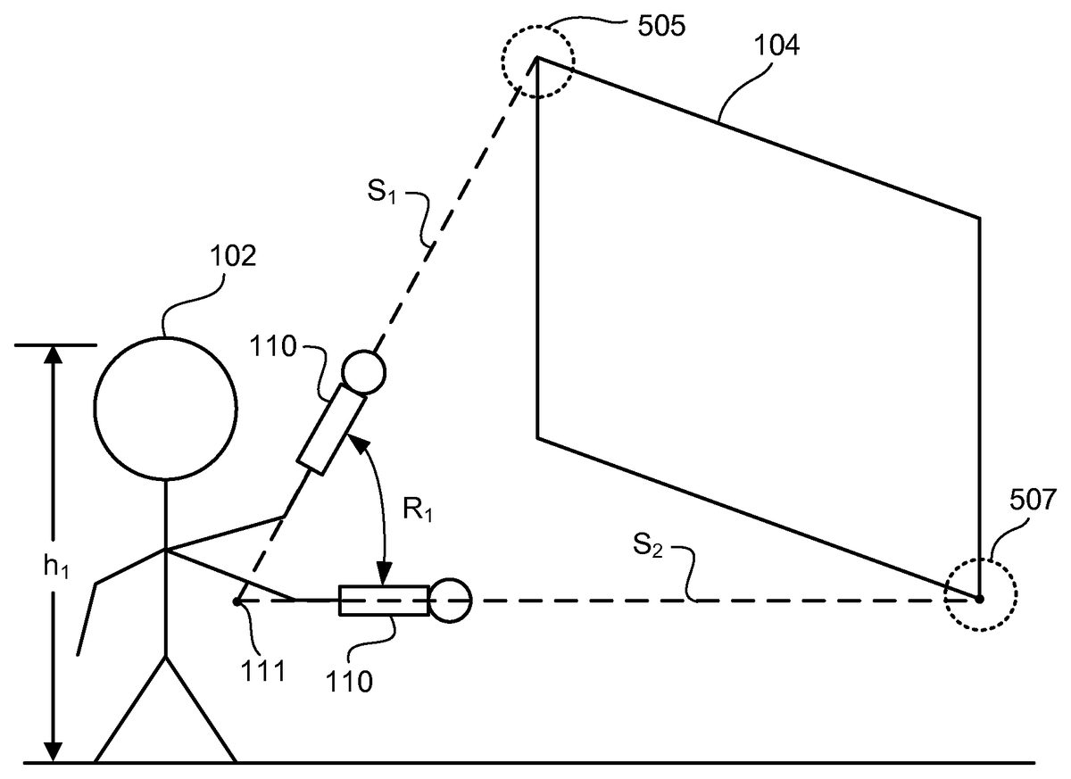
FIG. 6Billustrates a calibration environment503used to generate a triangulation between corners505and507of display104and tracked object110when a comfortable height of a user102is being calibrated. Comfort Calibration module404prompts the user102to point to top left corner505and then at bottom right corner507. When the user102points first to the top left corner505and then to the bottom right corner507, the range R1of motion of tracked object110develops. The range R1is an angle formed between two sides s1and s2of a triangle. The triangle has the top left corner505and bottom right corner507as two vertices. A third vertex is formed by an intersection, e.g., a point111. The intersection is formed by extrapolating a line, e.g., the side s1, formed between the top left corner505and tracked object110and another line, e.g., the side s2, formed between the bottom right corner507and the tracked object110.
FIG. 6Cillustrates a calibration environment509used to generate a triangulation between corners505and507of display104and tracked object110when a comfortable height of a user102′ is being calibrated. When user102′ is prompted to point from top left corner505to bottom right corner507, the user102′ performs a motion to generate a range R2. The Comfort Calibration module404provides the ranges R1and R2to Comfortable height Setting module406.
Upon receiving the ranges, Comfortable height Setting module406determines that the range R1is greater than the range R2to further determine that the comfortable height ch1is greater than a comfortable height ch2of the user102′.
FIG. 7Ais an isometric view of an embodiment of a game environment used to illustrate a nonapplication of bias based on comfortable height of user102. In this case, there was a lack of existence of an error between a position of an object image displayed on display104and a cursor generated by selection of a button by the user102. In such a case, Bias Selection module414avoids selecting a bias for the user102in providing the comfortable height ch1of the user102to game logic102. Display104uses game logic102to generate an image of a baseball650on display104lacking application of a bias.
FIG. 7Bis an isometric view of an embodiment of a game environment used to illustrate application of bias based on comfortable height ch2of user102′. Bias Selection module414removes an error of an angle γ, which in this case is greater than zero, between an actual point line and a bias point line to provide a comfortable height setting to Comfortable height Setting module406. The actual point line extends from tracked object110towards display104when the user102′ is at an uncomfortable height. The bias point line extends from tracked object110towards display104when the user102′ is at a comfortable height. The comfortable height of the user102′ is provided by Comfortable height Setting module406to game logic102. Display104uses game logic102to generate an image of a baseball650at the comfortable height rather than at the uncomfortable height.
FIG. 7Cis an isometric view of an embodiment of a game environment used to illustrate application of bias based on comfortable height ch3of a user102″. The comfortable height ch3is greater than ch1, which is greater than ch2. Bias Selection module414removes an error of an angle γ, which in this case is less than zero, between an actual point line and a bias point line to provide a comfortable height setting to Comfortable height Setting module406. The actual point line extends from tracked object110towards display104when the user102″ is at an uncomfortable height. The bias point line extends from tracked object110towards display104when the user102″ is at a comfortable height. The comfortable height of the user102″ is provided by Comfortable height Setting module406to game logic102. Display104uses game logic102to generate an image of a baseball650at the comfortable height rather than at the uncomfortable height.
It is noted that in one embodiment, a comfortable height correlates to a height of a user. For example, the comfortable height ch1correlates to a height h1of the user102, the comfortable height ch1correlates a height h2of the user102′, and the comfortable height ch3correlates to a height h3of the user102″. As another example, the taller a user, the greater is the user's comfortable height. User102is taller than user102′ and the comfortable height ch1height is greater than the comfortable height ch2. The height h of the user is thus an approximation based on the comfortable height.
FIGS. 8A-8Care top views of embodiments of a game environment used to illustrate an application of bias based on side-stepping. As shown inFIG. 8A, the tracked object110is at a center position p1passing through center513. The user102is pointing tracked object110towards center513.
As shown inFIG. 8B, the user102side steps to the right of the center position p1during game interactive play408. The user102may side step to the right to point to an object image at a point515on display104to the right of center position p1. When the user102side steps to the right, it may be natural for the user102to point tracked object110towards center513instead of towards point515. When the user102side steps to the right, the tracked object110is at position p2and forms an angle φ1with respect to a position of tracked object110at position p1. Bias For Success module420(FIG. 4B) determines an angle θ1between position p2and a line l1. The line l1is formed between center513and tracked object110that points towards center513after the user102side-steps to the right. The Gearing Table storage418may adjust the angle θ1, which is a function of the position p2and/or the angle φ1.
As further shown inFIG. 8C, the user102side steps to the left of center position p1. The user102may side step to the left to point to an object image at a point517on display104to the left of center position p1. When the user102side steps to the left, it may be natural for the user102to point tracked object110towards center513instead of towards point517. When the user102side-steps to the left, the tracked object110is at position p3and forms an angle φ2with respect to a position of the tracked object110at position p1. Bias For Success module420determines an angle θ2between position p3and a line l2. The line l2is formed between center513and tracked object110pointing towards center513after the user side-steps to the left. The Gearing Table storage418may apply weights to the angles θ1, which is a function of the position p3and/or the angle φ2.
Bias For Success module420(FIG. 4B) determines whether tracked object110forms the angle φ1or the angle φ2. Upon determining that the tracked object110forms the angle θ1, the Bias For Success module420generates and sends the angle θ1via the side-step gearing table419ato provide to Bias Applicator module422. On the other hand, upon determining that the tracked object110forms the angle φ2, the Bias For Success module420generates and sends the angle θ2via side-step gearing table419ato provide to Bias Applicator module422. Moreover, upon determining that the tracked object110does not form the angles φ1or the angle φ2, the Bias For Success module420avoids generating and sending the angles θ1and θ2to the side-step gearing table419a. The tracked object110does not form the angles φ1and φ2when the tracked object110is at the position p1.
When the user102side-steps to the right during game play, Bias Applicator module422applies the angle θ1to the line l1to apply bias to change a cursor from pointing towards center513to point towards point515. Comparatively, when the user102side-steps to the right during game play, Bias Applicator module422applies the angle θ2to the line l2to apply bias to change a cursor from pointing towards center513to point towards point517. If an angle θ1or θ2is not received, the Bias Applicator module422avoids applying the angle θ1or θ2during game play to avoid applying a bias.
Bias Applicator module422controls Game Logic244to display on display104a cursor at point515instead of at center point513when the user103side-steps to the right. Moreover, Bias Applicator module422controls Game Logic244to display on display104a cursor at point517instead of at center point513when the user103side-steps to the left.
FIGS. 9A-9Care isometric views of embodiments of a gaming environment to illustrate an application of bias based on a relation between depth and strength. InFIG. 9A, the tracked object110is at a location l1. When the user102hits a ping pong ball image622by using the tracked object110, the ping pong ball image622lands at a position pp1on table image624.
As shown inFIG. 9B, when the user102moves forward to displace the tracked object110to a location l2a distance d1from the location l1, a strength applied by the user102to the ping pong ball image622may increase from strength applied by the user102to ping pong ball image622with the tracked object110at location l1. Without application of a bias, the increase in the application of strength results in the ping pong ball image622to be displayed at a position pp2rather than at position pp1. The position pp2is displaced a depth dp1from the position pp1. The Bias For Success module420maps the displacement d1to the depth dp1to send the depth dp1via depth-to-strength gearing table419bto the Bias Applicator module422.
As further shown inFIG. 9C, when the user102moves back to displace the tracked object110to a location l3a distance d2from the location l1, a strength applied by the user102to the ping pong ball image622may decrease from strength applied by the user102to ping pong ball image622with the tracked object110at location l1. Without application of a bias, the decrease in the application of strength results in the ping pong ball image622to be displayed at a position pp3rather than at position pp1. The position pp3is displaced a depth dp2from the position pp1. The Bias For Success module420maps the displacement d2to the depth dp2to send the depth dp2via depth-to-strength gearing table419bto Bias Applicator module422.
Bias For Success module420(FIG. 4B) determines whether tracked object110is displaced by the distance d1or d2. Upon determining that the tracked object110is displaced by the distance d1, the Bias For Success module420generates and sends the depth dp1via the depth-to-strength gearing table419bto provide to the Bias Applicator module422. Comparatively, upon determining that the tracked object110is displaced by the distance d2, the Bias For Success module420generates and sends the depth dp2via depth-to-strength gearing table419bto provide to the Bias Applicator module422. Moreover, upon determining that the tracked object110is not displaced from the location l1, the Bias For Success module420avoids generating and sending the depth dp1or dp2.
If Bias Applicator module422receives the depth dp1from the Bias For Success module420, the Bias Applicator module422applies the depth dp1to the ping pong ball image622at location pp2. Also, if Bias Applicator module422receives the depth dp2from the Bias For Success module420, the Bias Applicator module422applies the depth dp2to the ping pong ball image622at location pp3. If a depth is not received from the Bias For Success module420, the Bias Applicator module422avoids applying the depth dp1or dp2.
When the user103steps forward, Bias Applicator module422provides the depth dp1to Game Logic244to display on display104ping pong ball image622at the position pp1instead of at the position pp2. Moreover, when the user103steps back, Bias Applicator module422provides the depth dp2to Game Logic244to display on display104ping pong ball image622at the position pp1instead of at the position pp3. Also, Bias Applicator module422avoids providing the depth dp1or dp2to game logic214when the controller110is at the location l1. Without the application of the depth dp1or dp2to game logic214, the ping pong ball image622is displayed at the position pp1.
FIGS. 10A and 10Bare side views of embodiments of a gaming environment used to determine whether a user applies an overarm or underarm motion to throw an object image. It should be noted that in one embodiment, data regarding motion of the tracked object110is received by the computer108from the tracked object110or from the image capture device106(FIG. 1). The motion data includes data regarding a pickup object location and data collected after reaching the pickup object location until a release location is reached. The pickup object location is a location of the tracked object110at which the user102selects a button on the tracked object110to pick up, e.g., hold, an object image on the display104. When the image is held, the image moves with a motion of the tracked object110. The release location is a location at which the image is released from being held. For example, a button on the tracked object110is released to release the image. When an image is released, the image stops moving with a motion of the tracked object110.
The computer108determines multiple criteria related to the motion of the tracked object110. For example, the computer108determines a multidirectional criterion independent of the pickup object location of the tracked object and one or more of a sample-based criterion, a direction-based criterion, and a depth-based criterion. Each of the sample-based criterion, the direction-based criterion and the depth-based criterion are determined using the pickup object location of the tracked object. The multidirectional criterion is determined without a need to use the pickup object location of the tracked object. In one embodiment, instead of the multidirectional criterion, a bounce criterion is determined.
To determine the multidirectional criterion, in one embodiment, the computer108determines whether the motion of the tracked object110occurs from a first location below and away from a reference location via a second location below and toward the reference location and via a third location above and away from the reference location to a fourth location above and toward the reference location. Examples of the reference location include an (x, y, z) point, e.g., (0, 0, 0), that is located at a corner of the display104, an (x, y, z) point, e.g., (0, 0, 0), that is located at a corner of a room in which the user102is playing a game with the tracked object110and the display104, etc. In one embodiment, the reference location is other than, e.g., not the same as, the pickup object location. It should be noted that in one embodiment, a location is away from the reference location or toward the reference location along a z-axis passing through the reference location. It should further be noted that in an embodiment, a location is above or below the reference location along a y-axis passing through the reference location.
In one embodiment, a direction in which a tracked object110is located with respect to the reference location, e.g., toward the reference location, away from the reference location, above the reference location, below the reference location, etc., is determined based on a direction in which a predetermined number of latest samples that are collected to reach the location of the tracked object110. For example, when three or more samples are collected latest in time to reach a location of the tracked object110and the three samples are collected along the z-axis away from the reference location, it is determined that the location of the tracked object110is in a direction away from the reference location. As another, when three or more samples are collected latest to reach a location of the tracked object110and the three samples are collected along the y-axis below from the reference location, it is determined that the location of the tracked object110is in a direction below the reference location.
Moreover, to determine the multidirectional criterion, in an embodiment, the computer108determines whether the motion of the tracked object110occurs from a fifth location below and away from the reference location via a sixth location below and toward the reference location and via a seventh location above and toward the reference location to an eighth location above and away from the reference location. Also, to determine the multidirectional criterion, in one embodiment, it is determined whether the motion of the tracked object110occurs from a ninth location above and away from the reference location via a tenth location above and toward the reference location and via an eleventh location below and away from the reference location to a twelfth location below and toward the reference location. Furthermore, to determine the multidirectional criterion, in an embodiment, the computer108determines whether the motion of the tracked object110occurs from a thirteenth location above and away from the reference location via a fourteenth location above and toward the reference location and via a fifteenth location below and toward the reference location to a sixteenth location below and away from the reference location.
In response to determining that the motion of the tracked object110occurs from the first location via the second and third locations to the fourth location, the computer108determines that an overarm motion of the tracked object110occurs. Moreover, in response to determining that the motion of the tracked object110occurs from the fifth location via the sixth and seventh locations to the eighth location, the computer108determines that an overarm motion of the tracked object110occurs.
It should be noted that although the motion from the seventh to the eighth location usually does not occur in case of overarm motion, the Bias For Success module420applies a bias to the motion from the seventh location to the eighth location to reverse a direction of the motion and provides a signal to the Game Logic244to move an image as if the overarm motion occurred. For example, an image would have moved in one direction in case of the motion from the seventh to the eight location without applying bias. In this example, when the bias is applied, the image moves in an opposite direction.
Upon determining that the motion of the tracked object110occurs from the ninth location via the tenth and eleventh locations to the twelfth location, the computer108determines that an underarm motion of the tracked object110occurred. Moreover, in response to determining that the motion of the tracked object110occurs from the tracked object110occurs from the thirteenth location via the fourteenth and fifteenth locations to the sixteenth location, the computer108determines that an underarm motion of the tracked object110occurs. It should be noted that although the motion from the fifteenth to the sixteenth location usually does not occur in case of underarm motion, the Bias For Success module420applies a bias to the motion to reverse a direction of the motion and provides a signal to the Game Logic244to move an image as if the underarm motion occurred.
It should be noted that the first, fifth, ninth, or thirteenth location is reached at or after reaching a pick-up object location and the fourth, eighth, twelfth, or sixteenth location is reached at or before, e.g., immediately before, reaching a release location. For example, no sample motion data is collected by the computer108between the release location and the fourth, eight, twelfth, or sixteenth location.
To determine the depth-based criterion, in one embodiment, the computer108determines whether a first location of the tracked object110is away from the reference location compared to a second location of the tracked object110. The first location is reached before or after reaching the second location and the first and second locations are reached after reaching the pickup object location. Moreover, the release location is reached immediately after the first location or second location that is reached later in time.
Also, upon determining that the first location is away the reference location compared to the second location, the computer108determines whether the first location is above or below the pickup object location. In response to determination that the first location is above the pickup object location, the computer108determines that the motion of the tracked object110is an overarm motion. On the other hand, in response to determining that the first location is below the pickup object location, the computer108determines that the motion of the tracked object110is an underarm motion.
When the user102is performing neither overarm nor underarm motion, the tracked object110is at a position m1. Referring toFIG. 10A, to determine the direction-based criterion, Game Logic244(FIG. 4B) prompts the user102to select a button on the tracked object110at position m1to pick up an object image and release the button on the tracked object110at position m3to throw the object image. The user may select the button when the tracked object110is at the position m1to pick up an object image, such as a baseball. Upon selecting the button, the user102moves his/her arm to move tracked object110from the position m1to position m2further to the position m3and releases the button. Upon releasing the button, the Bias For Success module420determines that the tracked object110bounced from the position m2, which is below the position m1, to the position m3, which is above the position m1. Moreover, the Bias for Success module420determines that a distance between the positions m2and m1is greater than a distance between the positions m1and m3. Accordingly, upon determining that the distance between the positions m2and m1is greater than a distance between the positions m1and m3, the Bias For Success module420determines that the user performed an underarm motion to throw an object image.
In other embodiments, to determine the sample-based criterion, the Game Logic244determines that a number of position data samples sampled by track position data module410(FIG. 4B) between positions m2and m1is greater than a number of position data samples sampled between positions m1and m3when the tracked object110moves from position m2after selecting the button to the position m3. The button is released at or immediately after the position m3. Upon determining that the number of samples is greater, Bias For Success module420determines that the user102performed an underarm motion to throw an object image. Referring toFIG. 10B, to determine the direction-based criterion, the Game Logic244prompts the user102to select a button on the tracked object110at position m1to pick up an object image and release the button on the tracked object110at position m5to throw the object image. Upon selecting the button, the user102bounces his/her arm to move tracked object110from the position m1to position m4further to the position m5and releases the button. Upon releasing the button, the Game Logic244determines that the tracked object110bounced from the position m4, which is above the position m1to the position m5, which is below the position m1. Moreover, the Game Logic244determines that a distance between the positions m4and m1is greater than a distance between the positions m1and m5. Accordingly, upon determining that the distance between the positions m4and m1is greater than a distance between the positions m1and m5, the Game Logic244determines that the user performed an overarm motion to throw an object image.
In other embodiments, to determine the sample-based criterion, Game Logic244determines that a number of position data samples sampled by track position data module410between positions m4and m1is greater than a number of position data samples sampled between positions m1and m5when the tracked object110moves from position m4after selecting the button to the position m5. The button is released at the position m5. Upon determining that the number of samples is greater, Game Logic244determines that the user102performed an overarm motion to throw an object image.
It should be noted that in some embodiments, to determine the sample-based criterion, the Game Logic244determines whether a number of samples sampled between a position n1and a position n3in front of the position n1is greater than a number of samples sampled between the position n1and a position n2behind the position n1. In response to determining that the number of samples is greater, the Game Logic244determines that the user102performed an overarm motion. On the other hand, upon determining that a number of samples sampled between the position n1and a position n4behind the position n1is greater than a number of samples sampled between the position n1and a position n5in front of the position n1, the Bias For Success module420determines that the user102performed an underarm motion.
In some embodiments, to obtain the bounce criterion, the user102performs more than two bounces with the tracked object110. For example, the user102moves the tracked object110from the position m2to the position m3but decides to avoid releasing the button at the position m3. Rather, the user102decides to further move the tracked object110from the position m3to the position m5and then releases the button. In such case, three bounces have occurred. One at the position m2, another at the position m3, and yet another bounce at the position m5. Gearing Table Generator418(FIG. 4B) may store position data for all the three bounces in the underarm/overarm gearing table419c. However, the Bias For Success Module420(FIG. 4B) sends the position data for the last two bounces, e.g., the bounce at position m3and the bounce at the position m5, to provide to the Bias Applicator Module422, and ignores the position data for the bounce at the position m2. Bias Applicator Module422applies the last two bounces to Game Logic244.
Bias For Success module420determines whether an overarm or an underarm motion occurred based on the last two bounces. For example, Bias For Success module420determines that to perform the bounces at the positions m3and the position m5, the tracked object110went from the position m3to the position m5. Because the position m3is above the position m1and the position m5is below the position m1, an overarm motion was performed by the user102. It should be noted that any number of bounces can be used to determine whether user102performed an underarm or overarm motion. For example, last three or last four bounces can be used instead of last two. Of course, a total number of bounces are greater than those used to determine whether user102performed an overarm or underarm motion. For example, last three bounces are used to determine whether the user102performed an overarm or underarm motion if more than three bounces are performed.
In several embodiments, Bias For Success module420assigns a weight to the samples sampled between positions m2and m1, a weight to the samples sampled between positions m1and m3, a weight to the samples sampled between positions m4and m1, a weight to the samples sampled between positions m1and m5, a weight to the samples sampled between positions n2and n1, a weight to the samples sampled between positions n1and n3, a weight to the samples sampled between positions n4and n1, a weight to the samples sampled between positions n1and n5, and/or a weight to all of the bounces to determine whether an overarm or underarm motion was performed by the user102. The weights are stored in Gearing Table storage418. The weighted samples and/or the weighted bounces are provided to Bias Applicator module422that applies a bias based on the weighted samples and/or the weighted bounces. Display104displays a game of Game Logic244according to the weighted samples and/or weighted bounces.
Upon determining the multiple criteria, the computer108assigns predetermined weights to the criteria. For example, the computer108multiplies a first weight with the multidirectional criterion to generate a first result, a second weight with the sample-based criterion to generate a second result, a third weight with the direction-based criterion to generate a third result, and a fourth weight with the depth-based criterion to generate a fourth result. The computer108determines whether a sum of the criteria with the assigned weights exceeds a threshold. For example, the computer108generates a sum of the first, second, third, and fourth results and determines whether the sum exceeds the threshold. Upon determining that the sum exceeds the threshold, the computer108determines that an overarm motion of the tracked object110occurred. On the other hand, upon determining that the sum does not exceed the threshold, the computer108determines that an underarm motion of the tracked object110occurred.
In one embodiment in which the computer108cannot determine whether an overarm or an underarm motion occurred, the computer108uses a default, which indicates that an underarm or an overarm motion occurred. For example, upon determining that the sum is equal to the threshold, the computer108determines that the motion is a default motion, e.g., overarm motion or underarm motion.
FIG. 11is an exemplary illustration of scene A through scene E with respective user A through user E interacting with game clients1102that are connected to server processing via the internet, in accordance with one embodiment of the present invention. A game client is a device that allows users to connect to server applications and processing via the internet. The game client allows users to access and playback online entertainment content such as but not limited to games, movies, music and photos. Additionally, the game client can provide access to online communications applications such as voice over Internet protocol (VOIP), text chat protocols, and email.
A user interacts with the game client via controller. In some embodiments the controller is a game client specific controller while in other embodiments, the controller can be a keyboard and mouse combination. In one embodiment, the game client is a stand-alone device capable of outputting audio and video signals to create a multimedia environment through a monitor/television and associated audio equipment. For example, the game client can be, but is not limited to a thin client, an internal Peripheral Component Interconnect-express (PCI-express) card, an external PCI-express device, an ExpressCard device, an internal, external, or wireless USB device, or a Firewire device, etc. In other embodiments, the game client is integrated with a television or other multimedia device such as a digital video recorder (DVR), Blu-Ray player, digital video disc (DVD) player or multi-channel receiver.
Within scene A ofFIG. 11, user A interacts with a client application displayed on a monitor1104A using a controller1106A paired with game client1102A. Similarly, within scene B, user B interacts with another client application that is displayed on monitor1104B using a controller1106B paired with game client1102B. Scene C illustrates a view from behind user C as he looks at a monitor displaying a game and buddy list from the game client1102C. While a single server processing module is shown, in one embodiment, there are multiple server processing modules throughout the world. Each server processing module includes sub-modules for user session control, sharing/communication logic, user geo-location, and load balance processing service. Furthermore, a server processing module includes network processing and distributed storage.
When a game client1102connects to a server processing module, user session control may be used to authenticate the user. An authenticated user can have associated virtualized distributed storage and virtualized network processing. Examples of items that can be stored as part of a user's virtualized distributed storage include purchased media such as, but not limited to games, videos and music etc. Additionally, distributed storage can be used to save game status for multiple games, customized settings for individual games, and general settings for the game client. In one embodiment, the user geo-location module of the server processing is used to determine the geographic location of a user and their respective game client. The user's geographic location can be used by both the sharing/communication logic and the load balance processing service to optimize performance based on geographic location and processing demands of multiple server processing modules. Virtualizing either or both network processing and network storage would allow processing tasks from game clients to be dynamically shifted to underutilized server processing module(s). Thus, load balancing can be used to minimize latency associated with both recall from storage and with data transmission between server processing modules and game clients.
The server processing module has instances of server application A and server application B. The server processing module is able to support multiple server applications as indicated by server application X1and server application X2. In one embodiment, server processing is based on cluster computing architecture that allows multiple processors within a cluster to process server applications. In another embodiment, a different type of multi-computer processing scheme is applied to process the server applications. This allows the server processing to be scaled in order to accommodate a larger number of game clients executing multiple client applications and corresponding server applications. Alternatively, server processing can be scaled to accommodate increased computing demands necessitated by more demanding graphics processing or game, video compression, or application complexity. In one embodiment, the server processing module performs the majority of the processing via the server application. This allows relatively expensive components such as graphics processors, RAM, and general processors to be centrally located and reduces to the cost of the game client. Processed server application data is sent back to the corresponding game client via the internet to be displayed on a monitor.
Scene C illustrates an exemplary application that can be executed by the game client and server processing module. For example, in one embodiment game client1102C allows user C to create and view a buddy list1120that includes user A, user B, user D and user E. As shown, in scene C, user C is able to see either real time images or avatars of the respective user on monitor1104C. Server processing executes the respective applications of game client1102C and with the respective game clients1102of users A, user B, user D and user E. Because the server processing is aware of the applications being executed by game client B, the buddy list for user A can indicate which game user B is playing. Further still, in one embodiment, user A can view actual in game video directly from user B. This is enabled by merely sending processed server application data for user B to game client A in addition to game client B.
In addition to being able to view video from buddies, the communication application can allow real-time communications between buddies. As applied to the previous example, this allows user A to provide encouragement or hints while watching real-time video of user B. In one embodiment, two-way real time voice communication is established through a client/server application. In another embodiment, a client/server application enables text chat. In still another embodiment, a client/server application converts speech to text for display on a buddy's screen.
Scene D and scene E illustrate respective user D and user E interacting with game consoles1110D and1110E, respectively. Each game console1110D and1110E are connected to the server processing module and illustrate a network where the server processing modules coordinates game play for both game consoles and game clients.
FIG. 12illustrates an embodiment of an Information Service Provider architecture. Information Service Providers (ISP)1202delivers a multitude of information services to users1216geographically dispersed and connected via network1205. An ISP can deliver just one type of service, such as stock price updates, or a variety of services such as broadcast media, news, sports, gaming, etc. Additionally, the services offered by each ISP are dynamic, that is, services can be added or taken away at any point in time. Thus, the ISP providing a particular type of service to a particular individual can change over time. For example, a user may be served by an ISP in near proximity to the user while the user is in her home town, and the user may be served by a different ISP when the user travels to a different city. The home-town ISP will transfer the required information and data to the new ISP, such that the user information “follows” the user to the new city making the data closer to the user and easier to access. In another embodiment, a master-server relationship may be established between a master ISP, which manages the information for the user, and a server ISP that interfaces directly with the user under control from the master ISP. In other embodiment, the data is transferred from one ISP to another ISP as the client moves around the world to make the ISP in better position to service the user be the one that delivers these services.
ISP1202includes Application Service Provider (ASP)1204, which provides computer-based services to customers over a network. Software offered using an ASP model is also sometimes called on-demand software or software as a service (SaaS). A simple form of providing access to a particular application program (such as customer relationship management) is by using a standard protocol such as Hypertext Transfer protocol (HTTP). The application software resides on the vendor's system and is accessed by users through a web browser using Hypertext markup language (HTML), by special purpose client software provided by the vendor, or other remote interface such as a thin client.
Services delivered over a wide geographical area often use cloud computing. Cloud computing is a style of computing in which dynamically scalable and often virtualized resources are provided as a service over the Internet. Users do not need to be an expert in the technology infrastructure in the “cloud” that supports them. Cloud computing can be divided in different services, such as Infrastructure as a Service (IaaS), Platform as a Service (PaaS), and Software as a Service (SaaS). Cloud computing services often provide common business applications online that are accessed from a web browser, while the software and data are stored on the servers. The term cloud is used as a metaphor for the Internet, based on how the Internet is depicted in computer network diagrams and is an abstraction for the complex infrastructure it conceals.
Further, ISP1202includes a Game Processing Server (GPS)1206which is used by game clients to play single and multiplayer video games. Most video games played over the Internet operate via a connection to a game server. Typically, games use a dedicated server application that collects data from players and distributes it to other players. This is more efficient and effective than a peer-to-peer arrangement, but it requires a separate server to host the server application. In another embodiment, the GPS establishes communication between the players and their respective game-playing devices exchange information without relying on the centralized GPS.
Dedicated GPSs are servers which run independently of the client. Such servers are usually run on dedicated hardware located in data centers, providing more bandwidth and dedicated processing power. Dedicated servers are the preferred method of hosting game servers for most PC-based multiplayer games. Massively multiplayer online games run on dedicated servers usually hosted by the software company that owns the game title, allowing them to control and update content.
Broadcast Processing Server (BPS)1208distributes audio or video signals to an audience. Broadcasting to a very narrow range of audience is sometimes called narrowcasting. The final leg of broadcast distribution is how the signal gets to the listener or viewer, and it may come over the air as with a radio station or TV station to an antenna and receiver, or may come through cable TV or cable radio (or “wireless cable”) via the station or directly from a network. The Internet may also bring either radio or TV to the recipient, especially with multicasting allowing the signal and bandwidth to be shared. Historically, broadcasts have been delimited by a geographic region, such as national broadcasts or regional broadcast. However, with the proliferation of fast internet, broadcasts are not defined by geographies as the content can reach almost any country in the world.
Storage Service Provider (SSP)1210provides computer storage space and related management services. SSPs also offer periodic backup and archiving. By offering storage as a service, users can order more storage as required. Another major advantage is that SSPs include backup services and users will not lose all their data if their computers' hard drives fail. Further, a plurality of SSPs can have total or partial copies of the user data, allowing users to access data in an efficient way independently of where the user is located or the device being used to access the data. For example, a user can access personal files in the home computer, as well as in a mobile phone while the user is on the move.
Communications Provider1212provides connectivity to the users. One kind of Communications Provider is an Internet Service Provider (ISP) which offers access to the Internet. The ISP connects its customers using a data transmission technology appropriate for delivering Internet Protocol datagrams, such as dial-up, digital subscriber line (DSL), cable modem, wireless or dedicated high-speed interconnects. The Communications Provider can also provide messaging services, such as e-mail, instant messaging, and short message service (SMS) texting. Another type of Communications Provider is the Network Service provider (NSP) which sells bandwidth or network access by providing direct backbone access to the Internet. Network service providers may consist of telecommunications companies, data carriers, wireless communications providers, Internet service providers, cable television operators offering high-speed Internet access, etc.
Data Exchange1214interconnects the several modules inside ISP1202and connects these modules to users1216via network1205. Data Exchange1214can cover a small area where all the modules of ISP1202are in close proximity, or can cover a large geographic area when the different modules are geographically dispersed. For example, Data Exchange1214can include a fast Gigabit Ethernet (or faster) within a cabinet of a data center, or an intercontinental virtual area network (VLAN).
Users1216access the remote services with client device1218, which includes at least a CPU, a display and input/output (I/O). The client device can be a PC, a mobile phone, a netbook, a Personal Digital Assistant (PDA), etc. In one embodiment, ISP1202recognizes the type of device used by the client and adjusts the communication method employed. In other cases, client devices use a standard communications method, such as HTML, to access ISP1202.
FIG. 13illustrates hardware and user interfaces that may be used to implement embodiments of the invention.FIG. 13schematically illustrates the overall system architecture of the Sony® PlayStation 3® entertainment device. A system unit1300is provided, with various peripheral devices connectable to the system unit1300. The system unit1300includes: a Cell processor1302; a Rambus® dynamic random access memory (XDRAM) unit1304; a Reality Synthesizer graphics unit1306with a dedicated video random access memory (VRAM) unit1308; and an I/O bridge1310. The system unit1300also comprises a Blu Ray® Disk BD-ROM® optical disk reader1312for reading from a disk1312aand a removable slot-in hard disk drive (HDD)1314, accessible through the I/O bridge1310. Optionally, the system unit1300also comprises a memory card reader1301for reading compact flash memory cards, Memory Stick® memory cards and the like, which is similarly accessible through the I/O bridge1310.
The I/O bridge1310also connects to six Universal Serial Bus (USB) 2.0 ports1316; a gigabit Ethernet port1318; an IEEE 802.11b/g wireless network (Wi-Fi) port1320; and a Bluetooth® wireless link port1322capable of supporting of up to seven Bluetooth connections.
In operation, the I/O bridge1310handles all wireless, USB and Ethernet data, including data from one or more game controllers110and1324. For example, when a user is playing a game, the I/O bridge1310receives data from the game controller110and1324via a Bluetooth link and directs it to the Cell processor1302, which updates the current state of the game accordingly.
The wireless, USB and Ethernet ports also provide connectivity for other peripheral devices in addition to game controllers110and1324, such as: a remote control1326; a keyboard1328; a mouse1330; a portable entertainment device1332such as a Sony PSP® entertainment device; a video camera such as a PlayStation®Eye Camera1334; a shape object1336; and a microphone1338. Such peripheral devices may therefore in principle be connected to the system unit1300wirelessly; for example, the portable entertainment device1330may communicate via a Wi-Fi ad-hoc connection, while the shape object1336may communicate via a Bluetooth link.
The provision of these interfaces means that the PlayStation 3 device is also potentially compatible with other peripheral devices such as digital video recorders (DVRs), set-top boxes, digital cameras, portable media players, Voice over Internet Protocol (IP) telephones, mobile telephones, printers and scanners. In addition, a legacy memory card reader1340may be connected to the system unit via a USB port1316, enabling the reading of memory cards of the kind used by the PlayStation® or PlayStation 2® devices.
The game controllers110and1324are operable to communicate wirelessly with the system unit1300via the Bluetooth link, or to be connected to a USB port, thereby also providing power by which to charge the battery of the game controllers110and1324. Game controllers110and1324can also include memory, a processor, a memory card reader, permanent memory such as flash memory, light emitters such as an illuminated spherical section, light emitting diodes (LEDs), or infrared lights, microphone and speaker for ultrasound communications, an acoustic chamber, a digital camera, an internal clock, a recognizable shape facing the game console, and wireless communications using protocols such as Bluetooth®, WiFi™, etc. The recognizable shape can be in a shape substantially of a sphere, a cube, parallelogram, a rectangular parallelepiped, a cone, a pyramid, a soccer ball, a football or rugby ball, an imperfect sphere, a section of a sphere, a truncated pyramid, a truncated cone, a baseball bat, a truncated cube, a polyhedron, a star, etc., or a combination of two of more of these shapes.
Game controller1324is a controller designed to be used with two hands, and game controller110is a single-hand controller with a ball attachment. In addition to one or more analog joysticks and conventional control buttons, the game controller is susceptible to three-dimensional location determination. Consequently gestures and movements by the user of the game controller may be translated as inputs to a game in addition to or instead of conventional button or joystick commands. Optionally, other wirelessly enabled peripheral devices such as the Sony PSP® portable device may be used as a controller. In the case of the Sony PSP® portable device, additional game or control information (for example, control instructions or number of lives) may be provided on the screen of the device. Other alternative or supplementary control devices may also be used, such as a dance mat (not shown), a light gun (not shown), a steering wheel and pedals (not shown) or bespoke controllers, such as a single or several large buttons for a rapid-response quiz game (also not shown).
The remote control1326is also operable to communicate wirelessly with the system unit1300via a Bluetooth link. The remote control1326comprises controls suitable for the operation of the Blu Ray™ Disk BD-ROM reader1312and for the navigation of disk content.
The Blu Ray™ Disk BD-ROM reader1312is operable to read CD-ROMs compatible with the PlayStation and PlayStation 2 devices, in addition to conventional pre-recorded and recordable CDs, and so-called Super Audio CDs. The reader1312is also operable to read DVD-ROMs compatible with the Playstation 2 and PlayStation 3 devices, in addition to conventional pre-recorded and recordable DVDs. The reader1312is further operable to read BD-ROMs compatible with the PlayStation 3 device, as well as conventional pre-recorded and recordable Blu-Ray Disks.
The system unit1300is operable to supply audio and video, either generated or decoded by the PlayStation 3 device via the Reality Synthesizer graphics unit (RSX)1306, through audio and video connectors to a display and sound output device1342such as a monitor or television set having a display1346and one or more loudspeakers1348, or stand-alone speakers1350. In one embodiment, voice and gaze inputs are utilized to play sound toward specific audio speakers according to the POG of the user. The audio connectors1358may include conventional analogue and digital outputs while the video connectors1360may variously include component video, S-video, composite video and one or more High Definition Multimedia Interface (HDMI) outputs. Consequently, video output may be in formats such as PAL or NTSC, or in 720p, 1080i or 1080p high definition.
Audio processing (generation, decoding and so on) is performed by the Cell processor1302. The PlayStation 3 device's operating system supports Dolby® 5.1 surround sound, Dolby® Theatre Surround (DTS), and the decoding of 7.1 surround sound from Blu-Ray® disks.
In the present embodiment, the video camera1334comprises a single Charge Coupled Device (CCD), an LED indicator, and hardware-based real-time data compression and encoding apparatus so that compressed video data may be transmitted in an appropriate format such as an intra-image based MPEG (motion picture expert group) standard for decoding by the system unit1300. The camera LED indicator is arranged to illuminate in response to appropriate control data from the system unit1300, for example to signify adverse lighting conditions. Embodiments of the video camera1334may variously connect to the system unit1300via a USB, Bluetooth or Wi-Fi communication port. Embodiments of the video camera may include one or more associated microphones and also be capable of transmitting audio data. In embodiments of the video camera, the CCD may have a resolution suitable for high-definition video capture. In use, images captured by the video camera may, for example, be incorporated within a game or interpreted as game control inputs. In another embodiment, the camera is an infrared camera suitable for detecting infrared light.
In general, in order for successful data communication to occur with a peripheral device such as a video camera or remote control via one of the communication ports of the system unit1300, an appropriate piece of software such as a device driver should be provided. Device driver technology is well-known and will not be described in detail here, except to say that the skilled man will be aware that a device driver or similar software interface may be required in the present embodiment described.
Embodiments of the present invention may be practiced with various computer system configurations including hand-held devices, microprocessor systems, microprocessor-based or programmable consumer electronics, minicomputers, mainframe computers and the like. Several embodiments of the present invention can also be practiced in distributed computing environments where tasks are performed by remote processing devices that are linked through a wire-based or wireless network.
With the above embodiments in mind, it should be understood that a number of embodiments of the present invention can employ various computer-implemented operations involving data stored in computer systems. These operations are those requiring physical manipulation of physical quantities. Any of the operations described herein that form part of various embodiments of the present invention are useful machine operations. Several embodiments of the present invention also relates to a device or an apparatus for performing these operations. The apparatus can be specially constructed for the required purpose, or the apparatus can be a general-purpose computer selectively activated or configured by a computer program stored in the computer. In particular, various general-purpose machines can be used with computer programs written in accordance with the teachings herein, or it may be more convenient to construct a more specialized apparatus to perform the required operations.
Various embodiments of the present invention can also be embodied as computer readable code on a computer readable medium. The computer readable medium is any data storage device that can store data, which can be thereafter be read by a computer system. Examples of the computer readable medium include hard drives, network attached storage (NAS), read-only memory (ROM), random-access memory, compact disc-ROMs (CD-ROMs), CD-recordables (CD-Rs), CD-rewritables (RWs), magnetic tapes and other optical and non-optical data storage devices. The computer readable medium can include computer readable tangible medium distributed over a network-coupled computer system so that the computer readable code is stored and executed in a distributed fashion.
Although the method operations were described in a specific order, it should be understood that other housekeeping operations may be performed in between operations, or operations may be adjusted so that they occur at slightly different times, or may be distributed in a system which allows the occurrence of the processing operations at various intervals associated with the processing, as long as the processing of the overlay operations are performed in the desired way.
Although the foregoing invention has been described in some detail for purposes of clarity of understanding, it will be apparent that certain changes and modifications can be practiced within the scope of the appended claims. Accordingly, the present embodiments are to be considered as illustrative and not restrictive, and the various embodiments of the present invention is not to be limited to the details given herein, but may be modified within the scope and equivalents of the appended claims.
Claims
- A method comprising: receiving an identification of a first corner of a display screen from a tracked object by associating a first position of the tracked object with the first corner, the associating of the first position with the first corner performed using image data from a capture device, the tracked object configured to be held by a user;receiving an identification of a second corner of the display screen from the tracked object by associating a second position of the tracked object with the second corner, the associating of the second position with the second corner performed using image data from the capture device;triangulating between the first and second corners and the tracked object to define an angle of movement of the tracked object;defining a height at which the tracked object is held by the user based on the angle of movement, the height defined to set a calibration;and using the calibration to adjust a motion input provided by the tracked object when utilized by the user, wherein the method is executed by a processor.
- The method of claim 1 , wherein the angle is formed between two adjacent sides of a triangle, the triangle formed by said triangulation, each adjacent side of the triangle extending via the tracked object.
- The method of claim 1 , wherein the tracked object includes a controller, the controller used to play a game that is displayed on the display screen.
- The method of claim 1 , wherein the two corners are located diagonally opposite to each other.
- The method of claim 1 , wherein the angle of movement is based on a set position of the display screen, a location of the user relative to the display screen, a state of the user, and a stature of the user.
- The method of claim 1 , wherein the height at which the tracked object is held includes an estimate of a distance from the tracked object to a reference location.
- The method of claim 1 , wherein the angle of movement is less when the user is of a shorter stature compared to when the user is of a taller stature, the taller stature longer than the shorter stature.
- The method of claim 1 , wherein the height at which the tracked object is held is defined without receiving a value of the height of the user.
- A method comprising: identifying a position of a tracked object in front of a display screen;generating data regarding prompting a user to identify two or more corners of the display screen and a center of the display screen, wherein the two or more corners include a first corner and a second corner;receiving an identification of the center of the display screen from the tracked object;establishing a position of a capture device relative to the display screen using the identification of the center;receiving an identification of a first corner of a display screen from the tracked object by associating a first position of the tracked object with the first corner, the associating of the first position with the first corner performed using image data from a capture device;receiving an identification of a second corner of the display screen from the tracked object by associating a second position of the tracked object with the second corner, the associating of the second position with the second corner performed using image data from the capture device;triangulating between the first and second corners and the tracked object and using the position of the capture device relative to the center of the display screen to define an angle of movement of the tracked object;defining a height at which the tracked object is held by the user based on the angle of movement, the height defined to set a calibration;and using the calibration to adjust a motion input provided by the tracked object when utilized by the user, wherein the method is executed by a processor.
- The method of claim 9 , wherein the angle of movement is based on a set position of the display screen, a location of the user relative to the display screen, a state of the user, and a stature of the user.
Disclaimer: Data collected from the USPTO and may be malformed, incomplete, and/or otherwise inaccurate.