U.S. Pat. No. 8,926,427
VIDEO GAME WITH SCREEN FLIP AND DUAL SETS OF COLLISION DATA
AssigneeNintendo Co., Ltd.
Issue DateApril 25, 2007
Illustrative Figure
Abstract
When there is an instruction for rotation during a game in a first field, a CPU core of a game apparatus obtains central coordinates in a second field after the rotation and coordinates (central coordinates) of a player object and BG object in steps S53 and S55. Then, the CPU core executes a rotation process in a hardware calculation circuit, for example, in steps S57 to S61. When detecting end of the rotation in a step S63, the CPU core executes a map switch process in a step S65. In the map switch process, the CPU core generates a second field according to second area data. Then, after generating the second field, the CPU core makes a hit determination according to the second area data in a step S7, for example.
Description
DETAILED DESCRIPTION Referring toFIG. 1, a game apparatus10of first exemplary embodiment includes a first liquid crystal display (LCD)12and a second LCD14. The LCD12and the LCD14are stored in a housing16so as to be located in predetermined positions. In this exemplary embodiment, the housing16is formed by an upper housing16aand a lower housing16b. The LCD12is stored in the upper housing16aand the LCD14is stored in the lower housing16b. Accordingly, the LCD12and the LCD14are closely arranged in such a manner to line up vertically (above and below). Some LCDs are used as displays in the first exemplary embodiment, and alternatively, EL (Electronic Luminescence) displays and plasma displays may be employed in place of the LCDs. As can be understood fromFIG. 1, the upper housing16ahas a plane shape little larger than a plane shape of the LCD12, and has an opening formed so as to expose a display surface of the LCD12from one main surface thereof. On the other hand, the lower housing16bhas a plane shape horizontally longer than the upper housing16a, and has an opening formed so as to expose a display surface of the LCD14at an approximately center of the horizontal direction. A power switch18is provided on a left side of the LCD14of the lower housing16b. In addition, the upper housing16ahas sound holes20aand20bfor speakers36aand36b(FIG. 2) on the right and left sides of the LCD12. Further, the lower housing16bis provided with a microphone hole20cfor a microphone (not shown) and an operating switch22(22a,22b,22c,22d,22e,22L and22R). Additionally, the upper housing16aand the lower housing16bare rotatably connected at a lower side (lower edge) of the upper housing16aand a part of an upper side (upper edge) of the lower housing16b. Accordingly, in a case of not playing a game, for example, if the upper housing16ais rotatably folded such that the display surface of the LCD12and the display surface of the LCD14are ...
DETAILED DESCRIPTION
Referring toFIG. 1, a game apparatus10of first exemplary embodiment includes a first liquid crystal display (LCD)12and a second LCD14. The LCD12and the LCD14are stored in a housing16so as to be located in predetermined positions. In this exemplary embodiment, the housing16is formed by an upper housing16aand a lower housing16b. The LCD12is stored in the upper housing16aand the LCD14is stored in the lower housing16b. Accordingly, the LCD12and the LCD14are closely arranged in such a manner to line up vertically (above and below).
Some LCDs are used as displays in the first exemplary embodiment, and alternatively, EL (Electronic Luminescence) displays and plasma displays may be employed in place of the LCDs.
As can be understood fromFIG. 1, the upper housing16ahas a plane shape little larger than a plane shape of the LCD12, and has an opening formed so as to expose a display surface of the LCD12from one main surface thereof. On the other hand, the lower housing16bhas a plane shape horizontally longer than the upper housing16a, and has an opening formed so as to expose a display surface of the LCD14at an approximately center of the horizontal direction. A power switch18is provided on a left side of the LCD14of the lower housing16b.
In addition, the upper housing16ahas sound holes20aand20bfor speakers36aand36b(FIG. 2) on the right and left sides of the LCD12. Further, the lower housing16bis provided with a microphone hole20cfor a microphone (not shown) and an operating switch22(22a,22b,22c,22d,22e,22L and22R).
Additionally, the upper housing16aand the lower housing16bare rotatably connected at a lower side (lower edge) of the upper housing16aand a part of an upper side (upper edge) of the lower housing16b. Accordingly, in a case of not playing a game, for example, if the upper housing16ais rotatably folded such that the display surface of the LCD12and the display surface of the LCD14are face to face with each other, it is possible to prevent the display surface of the LCD12and the display surface of the LCD14from being damaged such as a flaw, etc. It is noted that the upper housing16aand the lower housing16bare not necessarily rotatably connected with each other, and may alternatively be provided integrally (fixedly) to form the housing16.
The operating switch22includes a direction instructing switch (cross switch)22a, a start switch22b, a select switch22c, an action switch (A button)22d, an action switch (B button)22e, an action switch (X button)22f, an action switch (Y button)22g, an action switch (L button)22L, and an action switch (R button)22R. The switch22ais placed on the left side of the LCD14on the one main surface of the lower housing16b. Other switches22bto22gare placed at the right of the LCD14on the one main surface of the lower housing16b. Furthermore, the switches22L and22R are arranged at left and right corners of the upper surface of the lower housing16b, which are located on both sides of a portion of connection with the upper housing16a.
The direction instructing switch22afunctions as a digital joystick, and is utilized for instructing a moving direction of a player character (or player object) to be operated by a user or player, instructing a moving direction of a cursor, and so forth by operating any one of four depression portions. Each of the depression portions can be given a particular role (guitar code in this exemplary embodiment). By operating one of the four depression portions, the player can specify (designate) the given role.
The start switch22bis formed by a push button, and is utilized for starting (restarting), temporarily stopping (pausing) a game, and so forth. The select switch22cis formed by the push button, and utilized for a game mode selection, etc.
The action switch22d, that is, the A button is formed by the push button, and allows the player character to perform an arbitrary action, except for instructing the direction, such as hitting (punching), throwing, holding (obtaining), riding, jumping, etc. For example, in an action game, it is possible to apply an instruction of jumping, punching, moving arms, etc. In a role-playing game (RPG) and a simulation RPG, it is possible to apply an instruction of obtaining an item, selecting and determining arms or command, etc. The action switch22e, that is, the B button is formed by the push button, and is utilized for changing a game mode selected by the select switch22c, canceling an action determined by the A button22d, and so forth.
The action switch22f, i.e., the X button, and the action switch22g, i.e., the Y button are formed by push buttons, and are used to perform auxiliary operations for the A button22dand the B button22ewhen the game cannot make progress only by these two buttons. However, the X button22fand the Y button22gcan also be used for the same operations as the A button22dand the B button22eperform. As a matter of course, the X button22fand Y button22gare not always required to be used in gameplay.
The action switch22L (left push button) and the action switch22R (right push button) are formed by the push button. The left push button (L button)22L and the right push button (R button)22R can perform the same operation as the A button22dand the B button22e, and also function as a subsidiary of the A button22dand the B button22e. Further, the L button22L and the R button22R can change each of the roles assigned to the direction switch22a, A button22d, B button22e, X button22f, and Y button22g, to another one. In this exemplary embodiment, pressing the L button22L changes the code assigned to the direction switch22ato another code.
Also, on a top surface of the LCD14, a touch panel24is provided. As the touch panel24, any one of kinds of a resistance film system, an optical system (infrared rays system) and an electrostatic capacitive coupling system, for example, can be utilized. In response to an operation (touch input) of depressing, stroking or touching with a stick26, a pen (stylus pen), or a finger (hereinafter, referred to as “stick26, etc.”) on a top surface (detection surface) of the touch panel24, the touch panel24detects coordinates of position of operation (touch position) by means of the stick26, etc. and outputs coordinate data corresponding to the detected coordinates.
In this exemplary embodiment, a resolution of the display surface of the LCD14is 256 dots×192 dots, and a detection accuracy of a detection surface of the touch panel24is also rendered 256 dots×192 dots in correspondence to the resolution of the display surface (this is the same or approximately the same as for the LCD12). However, detection accuracy of the detection surface of the touch panel24may be lower than the resolution of the display surface of the LCD14, or higher than it.
The LCD12and the LCD14can display different game screens. In a race game, for example, one LCD may display a screen indicating a view from a driving seat, and the other LCD may display a screen for the entire race (course). Also, in an RPG, one LCD may display a map and characters such as player character, and the other LCD may display items owned by the player character. Further, one LCD (the LCD12in this exemplary embodiment) may display a game screen for playing a game, and the other LCD (the LCD14in this exemplary embodiment) may display a game screen (operating screen) containing operational objects such as lines and graphics (including icons) for operating the game. Furthermore, using the two LCDs12and14together as one screen, it is possible to display an enormous creature (enemy character) to be defeated by the player character.
Thus, through operation of the touch panel24with the stick, etc.26, the player can point to (designate) an image of any of player characters, enemy characters, item characters, and operational objects, which are displayed on the screen of the LCD14, or can select (input) a command. In addition, the player can change a direction of a virtual camera (viewpoint) provided in a three-dimensional game space or can specify a direction of scrolling (gradually moving) game screen (map).
Besides, according to the kind of the game, the touch panel24can be used for other input instructions. For example, it is possible to input a coordinate input instruction or input handwritten characters, numbers, symbols, etc. to the LCD14.
As stated above, the game apparatus10has the LCD12and the LCD14as a display portion of two screens, and by providing the touch panel24on an upper surface of any one of them (LCD14in the first exemplary embodiment), the game apparatus10has the two screens (LCD12,14) and the two operating portions (22,24).
Additionally, in this exemplary embodiment, the stick26can be stored in a housing portion (indicated by dotted lines inFIG. 1) provided in the lower housing16b, for example, and taken out therefrom as necessary. However, in a case of not preparing the stick26, it is not necessary to provide the housing portion.
Also, the game apparatus10includes a memory card (or cartridge)28, and the memory card28is detachable, and inserted into a loading slot30(indicated by dotted lines inFIG. 1) provided on a rear surface or a lower edge (bottom surface) of the lower housing16b. Although omitted inFIG. 1, a connector32(seeFIG. 2) is provided at a depth portion of the loading slot30for connecting a connector (not shown) provided at an end portion of the memory card28in the loading direction, and when the memory card28is loaded into the loading slot30, the connectors are connected with each other, and therefore, the memory card28is accessible by a CPU core34(seeFIG. 2) of the game apparatus10.
Although not illustrated inFIG. 1, speakers36aand36b(seeFIG. 2) are provided in a position corresponding to the sound holes20aand20binside the upper housing16a.
Furthermore, although omitted inFIG. 1, for example, a battery accommodating box is provided on a rear surface of the lower housing16b, and a volume switch, an external expansion connector, an earphone jack, etc. are provided on a bottom surface of the lower housing16b.
FIG. 2is a block diagram showing an electric configuration of the game apparatus10. Referring toFIG. 2, the game apparatus10includes an electronic circuit board38, and on the electronic circuit board38, circuit components such as a CPU core34, etc. are mounted. The CPU core34is connected to the connector32via a bus40, and is connected with a RAM42, a first graphics processing unit (GPU)44, a second GPU46, an input-output interface circuit (hereinafter, referred to as “I/F circuit”)48, and an LCD controller50.
The connector32is detachably connected with the memory card28as described above. The memory card28includes a ROM28aand a RAM28b, and although illustration is omitted, the ROM28aand the RAM28bare connected with each other via a bus and also connected with a connector (not shown) to be connected with the connector32. Accordingly, the CPU core34gains access to the ROM28aand the RAM28bas described above.
The ROM28astores in advance a game program for a game (virtual game) to be executed by the game apparatus10, image data (letter and character images, background images, item images, icon (button) images, message images, etc.), data of sound (music) required for the game (sound data), etc. The RAM (backup RAM)28bstores (saves) proceeding data and result data of the game.
The RAM42is utilized as a buffer memory or a working memory. That is, the CPU core34loads the game program, the image data, the sound data, etc. stored in the ROM28aof the memory card28into the RAM42, and executes the loaded game program. The CPU core34executes a game process while storing in the RAM42data (game data and flag data) temporarily generated in correspondence with a progress of the game.
Besides, such the game program, the image data, the sound data, etc. are loaded from the ROM28aentirely at a time, or partially and sequentially so as to be stored (loaded) into the RAM42.
However, the ROM28aof the memory card28also stores a program for an application other than the game and stores image data required for execution of the application. Also, the ROM28amay store sound (music) data as necessary. In this case, the game apparatus10executes the application.
Each of the GPU44and the GPU46forms a part of a rendering means, is constructed by, for example, a single chip ASIC, and receives a graphics command (graphics command) from the CPU core34to generate game image data according to the graphics command. However, the CPU core34provides each of the GPU44and the GPU46with an image generating program (included in the game program) required for generation of the game image data in addition to the graphics command.
Furthermore, the GPU44is connected with a first video RAM (hereinafter, referred to as “VRAM”)52, and the GPU46is connected with a second VRAM54. The GPU44and the GPU46obtain data required for the GPU44and the GPU46to execute the graphics command (image data: character data, texture data, etc.) by access to a first VRAM52and a second VRAM54, respectively.
Also, the CPU core34writes the image data required for graphics drawing into the first VRAM52and the second VRAM54via the GPU44and the GPU46. The GPU44accesses the VRAM52to generate the game image data for graphics drawing, and the GPU46accesses the VRAM54to generate the game image data for graphics drawing.
The VRAM52and the VRAM54are connected to the LCD controller50. The LCD controller50includes a register56, and the register56consists of, for example, one bit, and stores a value of “0” or “1” (data value) according to an instruction of the CPU core34. In a case that the data value of the register56is “0”, the LCD controller50outputs the game image data generated by the GPU44to the LCD12, and outputs the game image data generated by the GPU46to the LCD14. Furthermore, in a case that the data value of the register56is “1”, the LCD controller50outputs the game image data generated by the GPU44to the LCD14, and outputs the game image data generated by the GPU46to the LCD12.
Besides, the LCD controller50reads out game image data directly from the VRAM52and the VRAM54, and reads out game image data from the VRAM52and the VRAM54via the GPU44and the GPU46.
The I/F circuit48is connected with the operating switch22, the touch panel24, the speakers36aand36b. Here, the operating switch22is the above-described switches22a,22b,22c,22d,22e,22g,22L and22R, and in response to an operation of the operating switch22, a corresponding operation signal is input to the CPU core34via the I/F circuit48. Furthermore, the coordinate position data from the touch panel24is input to the CPU core34via the I/F circuit48. In addition, the CPU core34reads the sound data necessary for the game such as game music (BGM), sound effects and voices (onomatopoeic sounds) of game characters (game objects), etc. from the RAM42, and outputs it from the speakers36a,36bvia the I/F circuit48.
Referring toFIG. 3, the RAM42has a program storage area58in which a game program60is stored. The game program60is entirely read at one time or is partially read as necessary from the above mentioned ROM28a, and stored in the program storage area58.
The game program60typically includes an initial setting program62, an object operation program64, a hit determination program66, a scroll program68, a rotation process program70, etc.
The initial setting program62, specifically shown inFIG. 11described later, is a program for rendering a player object and BG objects in a field with a designated field number (set in an area flag80described later).
The object operation program64controls the player object's movements and actions (jumping, walking, fighting, etc.) according to an operation signal input by a player through manipulation of the operating means26of the controller22.
The hit determination program66, specifically shown inFIG. 12described later, makes a determination on the presence or absence of a hit (contact, collision) of the player object against a BG object. When the two objects are in the hit state, the program finds a direction of the player object's contact with the BG object (in which direction the player object has contacted the BG object), and also subjects the player object and/or the BG object to a preset process according to the contact direction.
The scroll program68, specifically shown inFIG. 15described later, is a program for scrolling the game screen or the field under an instruction for scrolling.
The rotation process program70, specifically shown inFIG. 16described later, is a program for rotating the game screen, i.e., the field, in response to an instruction for rotation.
The RAM42further has a data storage area72in which an object data storage area74is provided. The object data storage area74stores player object data and BG object data.
As aforesaid, the player object is an object whose movements and actions can be controlled by the game player through the manipulation of the controller22. The player object data includes image data on such a player object and attribute data previously provided to the player object, such as a plurality of predetermined hit determination points (five in this exemplary embodiment) A1 to A5 and a reference point B as shown inFIG. 4.
The BG object is an object incapable of being operated or controlled by the game player, and forms a background (BG) image as a still picture, for instance. One example of such a BG object is given inFIG. 5. However, needless to say, the BG object shown inFIG. 5is a mere exemplification. The BG object may be also called BG data in some instances.
A BG object 1 shown inFIG. 5is a wall block. The wall block causes no damage to the player object and limits the player object's movable range because the player object cannot go ahead any further when hitting the wall block. When the player object makes contact with the wall block from the lower side, the wall block is vibrated and, if any item or the like is hidden behind the wall block, the item makes its appearance. A BG object 2 shown inFIG. 5is a fixed block. The fixed block is the same as the wall block in that it causes no damage to the player object and limits the player object's movable range because the player object cannot go forward any further when hitting against the fixed block. However, the player object cannot make the fixed block vibrate from the lower side and there is no item or the like hidden behind the fixed block.
Meanwhile, as for BG objects 3 (4) and 5 (6) shown inFIG. 5, the BG object 3 turns into the BG object 4 by its rotation and vice versa, and the BG object 5 turns into the BG object 6 by its rotation and vice versa. In this exemplary embodiment, the BG object 3 is called “prickles” and the BG object 4 is called “icicles”. Also, in this exemplary embodiment, the BG object 5 is called “hill” and the BG object 6 is called “ceiling”.
For example, the attributes of the BG objects 3 (4) and 5 (6) are specifically decided as listed in Tables 1 to 4 below.
For a description of the attributes with application of table 1 to this exemplary embodiment, the BG object 3 “prickles” causes some damage to the player object when contacted by the player object from the upper side because this object has “prickles” on upper side thereof. However, the BG object 3 causes no damage to the player object when contacted by the player object from any of the other sides, lower, left and right, and the player object just gets stuck on that side. Also, the BG object 1 cannot move by itself and is represented as a stationary object.
As can be well understood fromFIG. 5, the BG object 4 is expressed by an image of the BG object 3 “prickles” that is rotated through 180 degrees. Accordingly, the image of a post-rotation BG object can be provided by rotating individual dots of a bitmap image (developed in the VRAM) by calculation, for example. Therefore, conventionally, a BG object whose image can be obtained by rotating another BG object has not been separately prepared as a post-rotation BG object. On this account, whenever the player object makes contact with a BG object, the computer or the CPU is required to determine whether the BG object is rotated or not, and if the BG object is being rotated, the computer or the CPU needs to determine by calculation from which side the player object will be damaged through contact with the BG object, for conversion of the hit attribute. This results in a heavy load on the computer or the CPU.
On the contrary, in this exemplary embodiment, the object data is also prepared for the BG object 4 whose image is identical to that of the post-rotation BG object 3, and the hit attribute of the BG object 4 is preset to the object data in correspondence with the hit attribute of the pre-rotation BG object 3. For example, the BG object 3 has “prickles” on upper side thereof, and thus the player object suffers damage when contacting the upper side of the BG object 3. On the other hand, the BG object 4 has “prickles” on a lower side thereof, and thus its attribute is configured so as to cause damage to the player object when contacted from the lower side.
In this exemplary embodiment, however, the BG object 3 is “prickles” displayed as a stationary object. The BG object 4 is “icicles” that may go downward, but this is an attribute associated with an action, not a hit attribute. Thus, it is not necessarily required to set the action attribute of the rotated BG object 4 so as to be identical or correspond to the action attribute of the pre-rotation BG object 3.
As described above, the hit attribute of the post-rotation BG object 4 is preset in correspondence with the hit attribute of the pre-rotation BG object 3. Thus, after the rotation of the game field, it is possible to make a hit determination on the player object by using the hit attribute of the BG object 4 as it is, thus making easier a rotation process that has contributed to an increased load on the CPU in the conventional art.
The same thing can be said to a relation between the BG object 5 “hill” shown in Table 3 and the BG object 6 “ceiling” shown in Table 4. The BG object 5 has a pre-rotation image and a hit attribute, and the BG object 6 has a post-rotation image and a hit attribute. To put it simply, since the BG object 5 is “hill”, when the player object contacts the object from the left side, the player object is subjected to a hit process in which it climbs a slope, and when the player object contacts the object from the upper side, the player object is subjected to a hit process in which it gets stuck on the side (this is a determination in the case of a 45-degree slope). Meanwhile, since the BG object 6 is “ceiling”, when the player object contacts the object from either the right side or the lower side, the player object is also subjected to a hit process in which it gets stuck on the side (this is a determination in the case of a 45-degree slope).
TABLE 13: PricklesContacted from upper sideCause damage(beforeContacted from lower sideMake get stuck on the siderotation)Contacted from left sideMake get stuck on the sideContacted from right sideMake get stuck on the sideActionStationary
TABLE 24: PricklesContacted from upper sideMake get stuck on the side(afterContacted from lower sideCause damagerotation)Contacted from left sideMake get stuck on the side[Icicles]Contacted from right sideMake get stuck on the sideActionMay go downward
TABLE 35: HillContacted from upper sideMake get stuck on the side(before(determination on 45-degreerotation)slope)Contacted from lower sideMake get stuck on the sideContacted from left sideMake climb a slope(determination on 45-degreeslope)Contacted from right sideMake get stuck on the sideActionStationary
TABLE 45: HillContacted from upper sideMake get stuck on the side(after rotation)Contacted from lower sideMake get stuck on the side[ceiling](determination on45-degree slope)Contacted from left sideMake climb a slopeContacted from right sideMake get stuck on the side(determination on45-degree slope)ActionStationary
Returning toFIG. 3, the data storage area72further has a field memory area76. The field memory area76is also called screen memory area, and is an area for storing or setting area data indicating a layout of the BG objects within the game field, having first area data for a pre-rotation layout and second area data for a post-rotation layout.
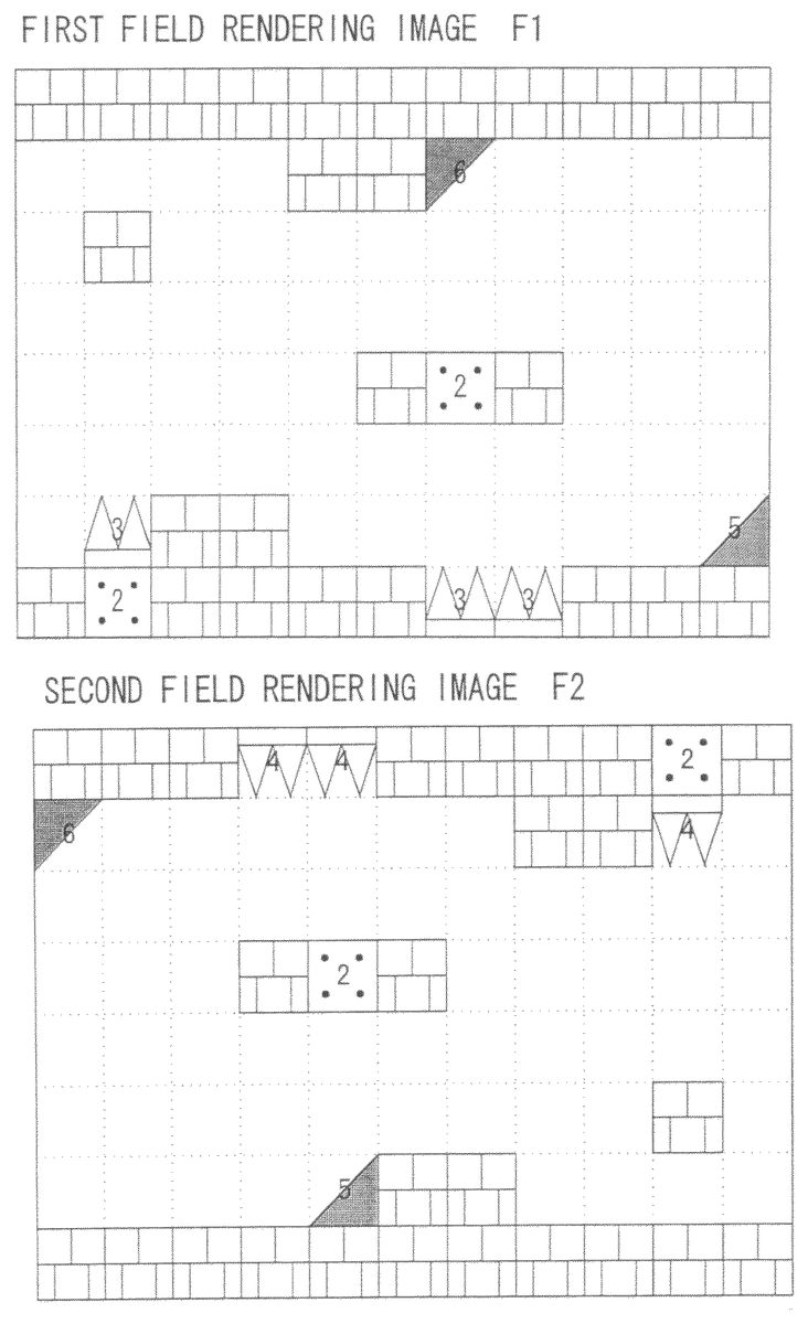
FIG. 6illustrates one example of first area data AD1. InFIG. 6, it is assumed that BG objects can be arranged and displayed with an 8 (vertical)×11 (horizontal) matrix on the whole game screen (field), for example. With the upper left corner as an origin point inFIG. 6, the BG object 1, i.e., the wall block is arranged in all the columns along the first line (horizontal). The same wall block is arranged in the fifth and sixth columns along the second line, in the second column along the third line, in the sixth and eighth columns along the fifth line, in the third and fourth columns along the seventh line, and in all the columns except for the second, seventh and eighth ones along the eighth line. Besides, the BG object 6 “ceiling” is placed in the seventh column along the second line, the BG object 2, i.e., the fixed block is arranged in the seventh column along the fifth line and the second column along the eighth line. In addition, the BG object 3, i.e., “prickles” is placed in the second column along the seventh line, the seventh and eighth columns along the eighth line. The BG object 5 “hill” is positioned in the eleventh column along the seventh line. As stated above, the data indicative of in which positions which BG objects will be displayed is referred to as area data (AD), and stored in the field memory area76.
Since the area data shown inFIG. 6represents a pre-rotation field and constitutes the first area data, the game screen according to the first area data AD1, that is, a first field rendering image F1 can be as shown inFIG. 7, for example. In the game image F1 shown inFIG. 7, the BG object 1 (wall block) is rendered and displayed in places given the number “1” as first area data as shown inFIG. 6, the BG object 2 (fixed block) in places given the number “2” as first area data, the BG object 3 (prickles) in places given the number “3” as first area data, the BG object 5 (hill) in places given the number “5” as first area data, and the BG object 6 (ceiling) in places given the number “6” as first area data, respectively.
One example of the second area data AD2 is illustrated inFIG. 8. InFIG. 8as well, the BG objects can be arranged and displayed with an 8 (vertical)×11 (horizontal) matrix in the same manner. The origin point shown inFIG. 6corresponds to a point at the lower right corner inFIG. 8. Specifically, the second field obtained by rotating the first field refers to a field obtained by rotating the first field through 180 degrees.
Thus, for the second area data AD2, circled line and column numbers obtained by reversing the line and column numbers shown inFIG. 6, are provided in their individual display places inFIG. 8for reference. More specifically, with an origin point at the lower right corner in the field memory shown inFIG. 8, the line numbers are provided upward in ascending order and the column numbers are provided leftward in ascending order. For example, the first line inFIG. 6is represented as the eighth line inFIG. 8, and the eleventh column inFIG. 6is shown as the first column inFIG. 8.
Since the second field inFIG. 8is obtained by rotating the first field inFIG. 6, the second area data AD2 is provided inFIG. 8so that the same BG objects as those inFIG. 6are arranged in the places indicated by the same line and column numbers as those inFIG. 6.
The BG object 1 (wall block) is provided in all the columns along the first line inFIG. 8. The same wall block is also arranged inFIG. 8in the fifth and sixth columns along the second line, in the second column along the third line, in the sixth and eighth columns along the fifth line, in the third and fourth columns along the seventh line, and in all the columns except for the second, seventh and eighth ones along the eighth line. In addition, the BG object 5 “hill” is provided in the seventh column along the second line. Although the BG object 6 “ceiling” is placed in this position in the first area data inFIG. 6, theFIG. 8field is obtained by rotating theFIG. 6field, and thus the BG object 6 as a rotatable BG object is replaced by the BG object 5 (hill) as a post-rotation BG object.
Besides, the BG object 2 as fixed block is placed in the seventh column along the fifth line and the second column along the eighth line inFIG. 8.
Further, the BG object 4, i.e., “icicles” is arranged in the second column along the seventh line and in the seventh and eighth columns along the eighth line. Although the BG object 3 “prickles” is positioned in these places in the first area data ofFIG. 6, the field in the second area data ofFIG. 8has a matrix obtained by rotatingFIG. 6, and thus the BG object 3 as a rotatable BG object is replaced by the BG object 4 as a post-rotation BG object.
The BG object 6 “ceiling” is provided in the eleventh column along the seventh line ofFIG. 8. Although the BG object 5 “hill” is positioned in this place in the first area data ofFIG. 6,FIG. 8represents the field obtained by rotatingFIG. 6, and thus the BG object 5 as a rotatable BG object is replaced by the BG object 6 as a post-rotation BG object.
The area data shown inFIG. 8is the second area data because it represents a post-rotation field, and a game screen according to the second area data AD2, that is, the second field rendering image F2 is as shown inFIG. 9, for example. In the game image F2 ofFIG. 9, the BG object 1 (wall block) is displayed in places given the number “1” as the second area data, the BG object 2 (fixed block) is displayed in places given the number “2” as the second area data, the BG object 4 (icicles) is displayed in places given the number “4” as the second area, the BG object 5 (hill) is displayed in places given the number “5” as the second area data, and the BG object 6 (ceiling) is displayed in places given the number “6” as the second area data, respectively. The second area data AD2 ofFIG. 8is used for making a hit determination as well as generating the post-rotation second field.
Besides, the game image F2 ofFIG. 9obtained by rotating the game image F1 ofFIG. 7can be displayed by performing rotation calculation with the use of a dedicated hardware unit to determine the positions of dots or pixels after the rotation and providing the corresponding dots ofFIG. 7in the post-rotation dot positions. Such rotation rendering may be implemented by any method.
Returning toFIG. 3again, the data storage area72has a flag area78in which an area flag80is set. The area flag80is a register for setting the area number for an area under a rendering process.
FIG. 10is a main flowchart indicating the operation of this exemplary embodiment. It should be noted that the main flowchart will be repeatedly executed at intervals of one frame or a few frames of the game machine12.
In a first step S1ofFIG. 10, the CPU core34executes an initial setting process. The details of the initial setting process are given inFIG. 11. In a step S21ofFIG. 11, the CPU core34sets an initial value, i.e., the area number for an area to be rendered, to the area flag80(FIG. 3). In a succeeding step S23, the CPU core34reads area data on the field associated with the area number set to the area flag80(e.g. the AD1 shown inFIG. 6) into the field memory area76shown inFIG. 3. Then, in a step S25, the CPU core34sends an instruction for rendering to the GPU44so that the BG objects can be rendered in the rendering area of the field according to the area data. As a result, the game image F1 shown inFIG. 7is displayed, for example. In a succeeding step S27, the CPU core34transmits an instruction for rendering to the GPU44in the same manner so that the player object can be rendered in a player object initial position in the same game field in which the BG objects were drawn in the above mentioned step S25. Thus, the initial setting process generates the first game field F1, and then the CPU core34returns to a next step S3ofFIG. 10.
In the step S3ofFIG. 10, the CPU core34fetches an operation signal from the operating switch22input through the I/F circuit48. In a step S5, the CPU core34moves or controls the player object displayed in the first game field F1 according to the operation signal.
After that, the CPU core34executes a hit determination process in a step S7ofFIG. 10. The hit determination process step is described in detail inFIG. 12. In a first step S31ofFIG. 12, the CPU core34determines BG objects that have made contact with the hit determination points. As previously described with reference toFIG. 4, the player object is provided with five hit determination points A1 to A5, for example, and in the step S31, the CPU core34detects the BG object in contact with any of these hit determination points A1 to A5. This contact determination or hit determination is carried out by watching for any overlap between the hit determination points and the BG objects as shown inFIG. 13, for example. The overlap between the hit determination point and the BG object is determined by the block-shaped rendering area of the BG object, not by the BG object's shape itself, as indicated by dotted lines inFIG. 13. This is because the BG objects have various kinds of shapes and thus setting a portion for overlap determination on each of those shapes would make the program complicated, resulting in an excessive load on the CPU core34.
In a succeeding step S33, the CPU core34determines a direction of contact between the hit determination points A1 to A5 of the player object and the BG object. The direction of contact can be determined by detecting which of the hit determination points of the player object has overlapped the BG object.FIG. 14shows an example in that the hit determination point A1 of the player object has overlapped the BG object. In this example, the CPU core34will determine that the player object has contacted the BG object 4 from the lower side. This is because, as apparent fromFIG. 4, the determination point A1 corresponds to the head of the player object and the head can make contact with only the lower side of the BG object. With this example included, Table 5 shows specific patterns for determination on contact direction.
TABLE 5Contact mannerDeterminationOnly hit determination point A1 in contactContact from lower sidewith BG objectOnly hit determination point A2 in contactContact from right sidewith BG objectOnly hit determination point A3 in contactContact from left sidewith BG objectEither hit determination point A4 or A5 orContact from upper sideboth in contact with BG objectBoth hit determination points A1 and A2 inContact from lower rightcontact with BG objectsideBoth hit determination points A1 and A3 inContact from lower left sidecontact with BG objectBoth hit determination points A2 and A4 inContact from upper rightcontact with BG objectsideBoth hit determination points A3 and A5 inContact from upper left sidecontact with BG object
Then, in a next step S35, the CPU core34executes a process according to the contact direction determined in the step S33. As previously described using Tables 1 to 4 as examples, the object data area74ofFIG. 3defines how control should be exercised on the player object, depending on the contact direction of the player object with each BG object. Thus, the CPU core34controls the player object according to the definition. In the example ofFIG. 14, for instance, the player object has contacted the BG object 4 from the lower side, and thus the CPU core34will exercise a process of causing damage to the player object, making reference to Table 2.
As above, upon completion of hit determination between the player object and the BG object in the step S7, the CPU core34executes a scroll process in a next step S9. The scroll process is described in detail inFIG. 15. More specifically, in the scroll process, the CPU core34firstly determines in a step S41whether there is an instruction for scrolling or not. If “YES”, the CPU core43renders a preset BG object at a destination place in the field. If “NO”, the CPU core43renders the currently set BG object again. In a next step S11ofFIG. 10, the CPU core34renders the player object based on the results of movement control in the step S5and hit determination in the step S7. Accordingly, such an image of the player object suffering damage from contact with the BG object is displayed in the step S11.
In a next step S13ofFIG. 10, the CPU core34executes a rotation process. Then, the CPU core34determines in a step S15whether the game has come to an end or not, and terminates the process if “YES” or return to the earlier step S3to continue the process if “NO”.
The rotation process of step S13is described in detail inFIG. 16. In a first step S51ofFIG. 16, the CPU core34determines whether there is an instruction for rotation or not. In this exemplary embodiment, the game field can be rotated by making the player object contact a predetermined item, for example. When the player object contacts a wall block from the lower side, the wall block vibrates and an item behind the wall block make its appearance. With the player object's contact with the item, an instruction for rotation is provided to the CPU core34according to the contact, and thus the determination in the step S51becomes “YES”.
However, the instruction for rotation can be also input by the player through manipulation of the operating switch22, instead of using the above mentioned method. In addition, the instruction for rotation can also be input by moving the player object to a predetermined position. Further, the instruction for rotation can also be given by making the player object contact with not only an item but also a predetermined object. Moreover, the instruction for rotation may be possibly provided under the condition that the player object continuously exists in the first game field for a predetermined period of time or more. Which one of the above methods to use for providing an instruction for rotation depends on the requirements of the game.
If “YES” in the step S51, the CPU core34obtains central coordinates in a field corresponding to the area flag (pre-rotation field) in a next step S53.FIG. 18illustrates one example of field rotation in which the first area data constitutes a pre-rotation field (first field) and the second area data a post-rotation field (second field). In the example ofFIG. 18, the origin point of absolute coordinates are provided at the upper left corner of the map, and coordinate values of x1, y1 are set as central coordinates of the first field, with respect to the origin point. Accordingly, in the step S53, the central coordinates x1, y1 are obtained.
In a succeeding step S55, the CPU core34obtains the coordinate values (central coordinates) of the player object in the first field in the absolute coordinates. The position (central coordinates) of the player object in the first field where the area flag is set to “1” inFIG. 8is indicated by the values of coordinates x2, y2 with respect to the origin point. In the step S55, data on values of the central coordinates of the player object is obtained, for example. The value data of the central coordinates can be easily obtained from bitmap data.
After that, in a step S57, the first field is rendered with a rotation through a designated degree of angle (e.g. an angle of rotation designated by frame) around the central coordinates of the drawing area, by means of a separately provided hardware calculation circuit (e.g. DSP), not by means of the CPU core34. In a step S59, the player object is displayed with no rotation, in the position at the angle designated in the step S57. If the display orientation of the player object is rotated, the rotated player object could be also rendered in the hardware calculation circuit with a decrease in the load on the CPU core34. However, if the changed orientation of the player object is returned to the original one immediately after the end of the rotation process, an unnatural feeling will be produced in the display of the player object. This is why this rendering process is carried out in such a manner as described above.
When receiving a calculation end signal from the calculation circuit, the CPU core34determines as “YES” in a next step S63. The calculation circuit repeats the rotation process until a degree of angle corresponding to the second field (post-rotation field) has been reached, by repeatedly executing the steps S57to S59so that the CPU core34detects the end of the rotation.
In the example ofFIG. 18, the central coordinates in the first and second game fields corresponding to each other between before and after the rotation are previously defined in the field memory area76(FIG. 3), and offset values from the central coordinates in the game field to the coordinates at the upper left corner in the game field is fixedly set.
In addition, by using the offset values from the central coordinates in the game field to the player character, it is possible to perform a rotation process only on the player character without changing the display coordinates in the game field.
There are other methods of rotation calculation, which include the one using the central coordinates and the absolute coordinates of the rendering area as shown inFIG. 18, the one using the central coordinates and the offset values from the origin point in the rendering area, and the one by which the coordinates (rotation central coordinates) of the player object is held in the absolute coordinates and the offset value therefrom is used, and so on. No more description will be given as to these methods.
If “YES” in the step S63ofFIG. 16, the CPU core34executes a map switch process in a next step S65. The map switch process is for switching map data, i.e., area data in preparation for a hit determination in the post-rotation field after the end of the rotation calculation in the steps S57to S59.
Referring toFIG. 17, in a first step S71, the CPU core34saves the area flag (area number) at that time as old area flag, and then carries out an area flag update by setting a new area number (post-rotation area number) to the area flag80ofFIG. 3(step S73).
After that, in a step S75, the CPU core34determines by calculation according to an equation 1 the central coordinates of a rendering area of the field corresponding to the current area flag (second field (post-rotation field)), from the central coordinates of the rendering area of the field corresponding to the old area flag (first field (pre-rotation field), as shown inFIG. 18.
Central coordinate in second field=x_max−x1,y_max−y1 [equation 1]
where x_max represents maximum value of X coordinate in the map data, and y_max represents the maximum value of Y coordinate in the map data.
Then, in a succeeding step S77, the CPU core34calculates the coordinate position of the player object in the second field, from the coordinates of the player object in the first field, according to an equation 2.
Central coordinate of player object=x_max−x2,y_max−y2 [equation 2]
where x_max represents maximum value of X coordinate in the map data, and y_max depicts the maximum value of Y coordinate in the map data.
Such a coordinate position refers to the central coordinates, and may be either absolute coordinates as shown inFIG. 18or other relative coordinates.
Then, in a succeeding step S81, the CPU core34reads the second area data AD2 for the post-rotation second field as shown inFIG. 8described above, into the field memory area76shown inFIG. 3. Now the map switch is completed, and thereafter the second area data is used for display of the post-rotation game field, i.e., the second field. More specifically, the CPU core34instructs the GPU44in steps S83and S85to render a BG object according to the second area data and render the player object in the coordinate position detected in the step S77.
As long as the game is played in the post-rotation game field, the game field is thereafter rendered by the second area data (step S11), and also the hit determination (step S7) and the scroll process (step S9) are carried out according to the second area data. That is, once the game field is rotated, the game processing is executed with a switch from the pre-rotation first area data to the post-rotation second area data.
The above exemplary embodiments are configured in such a manner that the first field is rotated clockwise through 180 degrees and turned into the second field. However, the angle of rotation or the degree and direction of rotation can be decided as appropriate. For example, the first field may be turned into the second field by rotating it clockwise or counterclockwise through 90 degrees.
Although certain exemplary embodiments have been described and illustrated in detail, it is clearly understood that the same is by way of illustration and example only and is not to be taken by way of limitation, the spirit and scope of these certain exemplary embodiments being limited only by the terms of the appended claims.
Claims
- A non-transitory computer readable storage medium storing a game program executed by a computer of a game apparatus that displays on a display device a state of rotation of a field in which a player character capable of being operated by a player is placed, said game program allowing said computer to execute: placing said player character within a first field formed by a plurality of objects and displaying on said display device a state of the first field containing at least the player character;rotating said first field through a predetermined degree of angle, wherein the predetermined degree of angle is 90 degrees, 180 degrees or 270 degrees, when a predetermined requirement is satisfied and displaying a state of the rotation on said display device;re-placing the player character placed in said first field, in a second field previously formed by a plurality of objects so as to be displayed in a manner identical to the first field rotated through said predetermined degree of angle when the rotation process of said first field has completed and of displaying on said display device a state of the second field containing at least the player character;a first contact determination of whether an object in the first field and said player character have made contact when said first field is displayed, and a second contact determination of whether an object in the second field and said player character have made contact when said second field is displayed.
- A non-transitory computer readable storage medium according to claim 1 , wherein said objects forming the first field and said objects forming the second field are provided with a definition of a process to be performed when making contact with said player character, and said computer further performs a contact process based on the definition previously provided to an object when contact between said player character and said object is determined in said first contact determination and said second contact determination.
- A non-transitory computer readable storage medium according to claim 1 , wherein said first contact determination and said second contact determination include a contact direction calculation for calculating in which direction said player character made contact with an object, from a state of contact between said player character and said object.
- A non-transitory computer readable storage medium according to claim 3 , wherein said object is previously provided with a definition of a process to be performed when making contact with said player character, with respect to each of the contact directions, and said game program allows said computer to perform a contact process based on the definition with respect to the determined contact direction previously provided to said object, when contact between said player character and said object is determined in said first contact determination and said second contact determination.
- A non-transitory computer readable storage medium according to claim 1 , wherein said predetermined requirement is that said player character moves to a predetermined position in said first field.
- A non-transitory computer readable storage medium according to claim 1 , wherein said predetermined requirement is that said player character makes contact with a predetermined object in said first field.
- A non-transitory computer readable storage medium according to claim 1 , wherein said predetermined requirement is that a predetermined period of time passes after said display device displays a state of said first field.
- A non-transitory computer readable storage medium according to claim 1 , wherein said player character is rotated as with an object in which the player character makes contact.
- A non-transitory computer readable storage medium according to claim 1 , wherein said player character is not changed in display direction and is rotated as with an object in which the player character makes contact.
- A non-transitory computer readable storage medium according to claim 1 , wherein said player character is not rotated as with an object in which said player character makes contact.
- A storage medium according to claim 1 , wherein images of said player character before and after rotation are prepared in advance, the image before rotation is displayed in said first field and the image after rotation is displayed in said second field.
- A game apparatus that displays on a display device a state of rotation of a field in which a player character capable of being operated by a player is placed, comprising: a first display for placing said player character within a first field formed by a plurality of objects and displaying on said display device a state of the first field containing at least the player character;a rotation display processor for rotating said first field through a predetermined degree of angle, wherein the predetermined degree of angle is 90 degrees, 180 degrees or 270 degrees, when a predetermined requirement is satisfied and displaying a state of the rotation on said display device;and a second display for re-placing the player character placed in said first field, in a second field previously formed by a plurality of objects so as to be displayed in a manner identical to the first field rotated through said predetermined degree of angle when the rotation process of said first field has completed by said rotation display processor and for displaying on said display device a state of the second field containing at least the player character a first contact determiner for determining whether an object in the first field and said player character have made contact when said first field is displayed, and a second contact determiner for determining whether an object in the second field and said player character have made contact when said second field is displayed.
- A game apparatus according to claim 12 , wherein said plurality of objects are provided with a definition of a process to be performed when making contact with said player character, further comprising: a first contact processor for performing a contact process based on the definition previously provided to an object when contact between said player character and said object is determined by said first contact determiner and said second contact determiner.
- A game apparatus according to claim 12 , said first contact determiner and said second contact determiner include a contact direction calculator for calculating in which direction said player character made contact with an object, from a state of contact between said player character and said object.
- A game apparatus according to claim 14 , wherein said object is previously provided with a definition of a process to be performed when making contact with said player character, with respect to each of the contact directions, further comprising: a second contact processor for performing a contact process based on the definition with respect to the contact direction calculated in said contact direction calculator previously provided to said object, when contact between said player character and said object is determined by said first contact determiner and said second contact determiner.
Disclaimer: Data collected from the USPTO and may be malformed, incomplete, and/or otherwise inaccurate.