U.S. Pat. No. 8,920,240
DIRECTIONAL GAME CONTROLLER
AssigneeGuillemot Corporation S.A.
Issue DateApril 19, 2011
Illustrative Figure
Abstract
The invention has for object a game controller having an actuator (2, 102) mobile in rotation in relation to a fixed part (3, 103), in such a way as to simulate a control of the rotation of a steering column of a simulated vehicle. According to the invention, the game controller implements means for detecting the displacement in rotation of the actuator (2, 102) comprising at least one Hall effect or magnetoresistive effect detecting unit, constituted of at least two elements, of which a permanent magnet and a magnetic sensor (24, 124). At least during the rotation of the actuator (2, 102), a first element is integral in rotation with the actuator (2, 102) and a second element is integral in rotation with said fixed part (3, 103).
Description
DETAILED DESCRIPTION 1. General Principle and Alternatives The actuators of game directional controllers are generally handlebars or steering wheels of which the angle of rotation in relation to the base is measured by the intermediary of a potentiometer. Other types of actuators can of course be considered, for example in order to simulate the control of a boat, of a space vessel, etc. The invention proposes to use a magnetic sensor and permanent magnet detection unit to measure the displacement in rotation, and where applicable in translation, of the actuator in relation to the fixed part of the game controller, in such a way as to avoid any contact between the means for measuring, and to obtain good precision. Note that such a detection unit can measure not only the angle of rotation of the actuator, but also the speed and the direction of rotation of the actuator. In what follows, systems based on the Hall effect shall be described. The same approaches can however be implemented with systems based on the magnetoresistive effect in particular, but not limited to, the giant magnetoresistive effect. Many implementations of the invention can be considered. A few examples are proposed hereinafter. 1.1 Alternative 1 In a first preferred embodiment, the magnetic sensor can be mounted mobile in relation to the fixed part, more precisely it can be integral with the actuator (including a part integral with the actuator) when the actuator pivots around the axis A. For example, the magnetic sensor can be placed on a PCB fixed in the actuator. The magnet can be mounted integral with the fixed part when the actuator pivots around the axis A. For example, the magnet can be mounted on a part fixed to the fixed part, this part can be a shaft (a shaft is ...
DETAILED DESCRIPTION
1. General Principle and Alternatives
The actuators of game directional controllers are generally handlebars or steering wheels of which the angle of rotation in relation to the base is measured by the intermediary of a potentiometer. Other types of actuators can of course be considered, for example in order to simulate the control of a boat, of a space vessel, etc.
The invention proposes to use a magnetic sensor and permanent magnet detection unit to measure the displacement in rotation, and where applicable in translation, of the actuator in relation to the fixed part of the game controller, in such a way as to avoid any contact between the means for measuring, and to obtain good precision. Note that such a detection unit can measure not only the angle of rotation of the actuator, but also the speed and the direction of rotation of the actuator. In what follows, systems based on the Hall effect shall be described. The same approaches can however be implemented with systems based on the magnetoresistive effect in particular, but not limited to, the giant magnetoresistive effect.
Many implementations of the invention can be considered. A few examples are proposed hereinafter.
1.1 Alternative 1
In a first preferred embodiment, the magnetic sensor can be mounted mobile in relation to the fixed part, more precisely it can be integral with the actuator (including a part integral with the actuator) when the actuator pivots around the axis A. For example, the magnetic sensor can be placed on a PCB fixed in the actuator. The magnet can be mounted integral with the fixed part when the actuator pivots around the axis A. For example, the magnet can be mounted on a part fixed to the fixed part, this part can be a shaft (a shaft is not necessarily cylindrical or tubular) extending according to the axis A.
1.2 Alternative 1 bis
In another example, this magnetic sensor (here mobile) can also be mounted in the fixed part, more precisely it can be integral with a linking part pivotally mounted on the fixed part, said linking part being intended to cooperate with an additional cavity of the actuator and a permanent magnet being integral with the fixed part of the controller. In this embodiment, the magnetic sensor is not in the actuator (i.e. it is not in the graspable part of the controller) but in the fixed part. When the actuator is assembled—in a removable or non-removable manner—to the linking part, the magnetic sensor which is fixed to the linking part becomes integral in rotation with the actuator. The angle of rotation of the actuator is identical to the angle of rotation of the linking part and the magnetic sensor interacts with the permanent magnet which is fixed in relation to the actuator.
1.3 Alternative 1 ter
In another example, the magnet can be placed in a part mobile in rotation in relation to the fixed part (for example, in the actuator or in a linking part, but mobile in rotation in relation to the actuator by mounting the magnet on a roller bearing) and the locking of the actuator to the fixed part at the same time blocks the magnet which can no longer turn in relation to the fixed part while still allowing for the rotation of the actuator in relation to the fixed part. The magnetic sensor is integral in rotation with the actuator (for example, it is in the actuator or in a part integral with the actuator when the actuator pivots in relation to the fixed part).
1.4 Alternative 2
In a second embodiment, the magnetic sensor can be mounted fixed in relation to the fixed part, more precisely it can be integral with the fixed part (including a part fixed in relation to the fixed part even when the actuator pivots around the axis A) when the actuator pivots around the axis A. For example, the magnetic sensor can be fixed in the fixed part. The magnet can be mounted integral with the actuator when the actuator pivots around the axis A. For example, the magnet can be fixed to the actuator or mounted on a fixed part—in a permanent or non-permanent manner—to the actuator.
In another example, the magnet integral in rotation with the actuator, and therefore mobile in relation to the fixed part is carried by a movable shaft (including a rod) which is integral with the actuator (including a linking part mobile in rotation around the axis A in relation to the fixed part) and which carries this magnet to the magnetic sensor. The magnetic sensor is then fixed to the fixed part.
2. Detailed Description of a First Preferred Embodiment
In the first preferred embodiment described in what follows, the actuator is a steering wheel (type steering wheel type of a saloon car) that can be detached from the fixed part. A permanent magnet is placed on the fixed part of the controller and a rotating biaxial (2D) Hall effect magnetic sensor in the steering wheel. The use of a Hall effect detecting unit, comprising at least two elements, of which a permanent magnet and a magnetic sensor, makes it possible to avoid the passing of an electric cable between the actuator and the fixed part (in the case of an actuator that cannot be separated from the fixed part) or to avoid an electric connector between the actuator and the linking part (the presence of a connector on the link between the actuator and the fixed part has in particular the disadvantage of generating a weakness as the connector is solicited at each release and taking of the actuator that can be detached).
In other embodiments, the magnet and the sensor can be inverted. Moreover, although the use of a single magnet and of a single sensor is advantageous, in particular in a position wherein they are aligned with the steering column, it can be considered to use several magnets and/or sensors distributed adequately.
Furthermore, in other embodiments, it can be considered that the Hall effect magnetic sensor may be a Hall effect 3D magnetic sensor.
FIG. 1is therefore a perspective view of an example of a game controller according to the invention. This controller1comprises an actuator2, in the form of a steering wheel mobile in rotation in relation to a fixed part3according to an axis A of rotation.
In this figure in particular can be distinguished control paddles25and buttons26arranged on the actuator.
According to the embodiment of the example,FIG. 2shows via a perspective view the actuator2, once separated from the fixed part3.
In order to assemble the actuator2with the fixed part3, a linking part31, pivotally mounted on the fixed part3, is intended to cooperate with an additional cavity21of the actuator2. The forms of the cavity21and of the linking part31are adjusted and make possible (when these two parts cooperate) the transmission of the rotating movement of the actuator2to the linking part31.
The controller comprises a system of fastening which makes it possible to fix and to lock reversibly the actuator2onto a linking part31. The system of fastening comprises, in this embodiment, an axis311arranged on the linking part31. This axis311is intended to position itself in a housing211located in the cavity21. The system of fastening further comprises a locking latch22arranged on the actuator2. This latch is formed of a an upper part221which is provided to position itself in a cavity312(which can be seen inFIG. 4) on the linking part31, and of a lower part222allowing the user actuate this latch22when he wants to separate the actuator2from the fixed part3.
Many other reversible or non-reversible means of fastening can of course be implemented, without leaving the scope of the invention, including a simple nesting by force of the steering wheel on the steering column33, in a simplified embodiment.
FIG. 3is a view in perspective of the actuator2seen from below. This figure shows in particular a connector23whereon a cable can be connected, for the supply of electrical energy and/or data transmission (for example, information on the rotation of the actuator2, and where applicable additional information, such as a speed change command, when the user acts on the paddles25, or other commands triggered by the activation of the buttons26(which can be seen inFIG. 1) located on the actuator2).
In another embodiment, the transmission of the data can be done wirelessly, via a radio frequency transmitter (for example, 2.4 GHz) placed in the actuator2; the supply of electrical energy then being provided by one or several batteries or accumulators placed in a case arranged in the actuator2or in a case that can be detached and that can be connected to the actuator2.
FIG. 4is a view in perspective of the fixed part3. In particular can be distinguished, at the front end of the fixed part3, the linking part31making it possible to carry out the interface between the actuator2and the fixed part3. This linking part31is mobile in rotation in relation to base32, according to the axis A and makes it possible to transmit to the steering column of the controller1, which in this embodiment is the shaft33(which can be seen inFIG. 5), the rotating movement exerted by the user on the actuator2and to a system for dynamisation and/or return of the steering wheel to neutral position (or centre return system), detailed herein below.
FIG. 5is a view in perspective of the inside of the fixed part3showing in particular the centre return system (via an elastic in this embodiment).
In this embodiment, the shaft33is designed in such a way that it constitutes the main axis of rotation of the controller1(which can therefore be qualified as a steering column of the controller1), and in that it also constitutes a part of the centre return system of the actuator2. The shaft33is formed from a single part but it could be formed from several parts fixed together (for example, a shaft and a return part whereon the forces for returning to the centre are executed). The shaft33(or steering column33) is mounted pivotingly around the axis A in relation to the support of the rotation mechanism35, with the latter being fixed to the fixed part3. The base32and the support of the rotation mechanism35provide the guiding in rotation of the steering column33. The steering column33is integral in rotation with the linking part31, and therefore with the actuator2, and therefore is displaced in rotation in the same manner as the actuator.
A fixed shaft36is fixed to the support of the rotation mechanism35(it is, for example, nested by force into the support of the rotation mechanism) and extends along the axis A to approach the magnet as close as possible to the magnetic sensor. The magnet is in this embodiment a round magnet37. The steering column33comprises an inside tubular space wherein penetrates the fixed shaft36and the round magnet37.
The circulation section of the space inside the steering column33is consequently complementary with the circulation section of the round magnet37. The steering column33therefore guides the round magnet37and recentres this magnet in relation to the axis A. This balances the mechanics and allows for an improvement in the precision of the measurement of the rotation (by avoiding an unbalance, an imbalance of the magnet, a bending of the shaft36). The measurement remains precise even in the case of bending of the steering column33.
In an alternative, the round magnet is placed on a fixed shaft36, and the shape of this magnet completes the guiding in rotation of the actuator2around the axis A, by guiding the rotation of the steering column33.
In another alternative, the fixed shaft36provides the guiding in rotation of the steering column33and therefore of the actuator2around the axis A. A rounded form of the magnet does not procure any advantage then and the form of the magnet can therefore be different (for example, a bar magnet can be fixed to the end of a housing arranged at the end of the shaft36).
In the embodiment shown inFIGS. 5 and 6, the steering column33is mobile in rotation in relation to the fixed part and to the base32, and the shaft36is fixed in relation to the fixed part3. This approach can be inverted. The shaft33can be fixed in relation to the fixed part3and to the base32. The shaft36is then mobile in rotation in relation to the fixed part3. The shaft33provides the guiding in rotation. The linking part could cooperate with the end of the shaft36and the actuator2(and provides a non-definitive link between them). The rotation of the actuator causes the rotation of the shaft36. The magnet can be fixed in relation to the fixed part3. For example, a round magnet can be nested by force into the shaft33. The shaft36is mobile in rotation in the round magnet (the round magnet then would contribute in part to the guiding in rotation). The PCB carrying the magnetic sensor24is then mobile in relation to the fixed part3.
As an alternative to this inverted approach, the round magnet could be fitted by force around the shaft33instead of being nested by force in the shaft33(the shaft33being fixed as we are in the inverted approach).
As a second alternative to this inverted approach, instead of being a round magnet nested by force in the shaft33, the magnet can be a bar magnet of a length less than the diameter of a cylindrical shaft36which could be nested by force—without exceeding radially—in a slot arranged in the end of such a shaft36(in this case the shaft33is no longer required, the guiding in rotation then able to be provided directly by the base32of the fixed part3, and the diameter of the shaft36can be greater).
In the first preferred embodiment shown inFIGS. 5 and 6, the steering column33comprises a first pulley, or a portion of a pulley,331, centred on the axis A, and two short shafts substantially parallel to the axis A and which each carry a small return pulley332(only one can be seen inFIG. 5, the other being mounted symmetrically). These pulleys331and332guide an elastic cord34of which the ends are anchored to the support of the rotation mechanism35fixed to the fixed part3, on two grooves351.
The axis of each of the pulleys332is integral with the steering column33. The pulleys332can more preferably turn around their axis. The ends of the elastic cord34are not fixed to the support of the rotation mechanism35, they are simply anchored, maintained integral with the support of the rotation mechanism35by the pre-compressing of the elastic cord. Indeed, each end of the elastic cord34is attached to a spool (a part in the shape of a sewing spool, i.e. a sort of pulley without an axis of rotation).
This spool thrusts itself against the support of the rotation mechanism35(the height of the spool does not allow it to cross over the groove351) but with the reserve of having first removed the fixed part3(or before having screwed the linking part31to the steering column33, the base32to the fixed part3and the support of the rotation mechanism35to the fixed part3), it is possible to radially pull on the spool (by opposing the elastic force) in order to remove the spool from the support of the rotation mechanism35by stretching the elastic beyond the groove351. This makes it possible to remove the elastic cord34from the centre return system, then remove the steering column33from the support of the rotation mechanism35.
The elastic cord34exerts, when the actuator2is displaced, a retaining force which tends to return the pulleys332and therefore the steering column33and the actuator2, to a neutral position (corresponding, in the case where a car is simulated, to a position of the wheels aligned with the simulated vehicle). The friction of the elastic cord34makes it possible to simulate a resistance in the steering. The elastic cord34exerts in particular a substantially vertical resultant force on the pulley331, which supports the steering column which improves the quality perceived by the user.
In another embodiment, the neutral return system of the steering wheel can use two extension springs having identical characteristics acting on either side of the steering column instead of an elastic cord and pulleys. In the neutral position of the actuator, the two extension springs are slightly pre-compressed. When the actuator2is displaced, each of the two springs exerts a retaining force which tends to return the steering column and the actuator to neutral position.
In yet another embodiment, the neutral return system (or return to the centre) of the steering wheel is even more simple: a torsion spring of which the inside diameter of the spires is slightly greater than the outside diameter of the steering column is placed around the steering column. This torsion spring cooperates with a lug arranged on the internal face of the part32of the base. This spring comprises only a few spires and, in final position, the branches of this spring are at three hundred sixty degrees (i.e. substantially parallel). In the neutral position of the actuator, the spring is slightly pre-compressed and the two branches of this torsion spring press against the lug. When the actuator2is displaced, one of the branches of the spring moves away from the lug and a retaining force tends to return this branch against the lug and therefore the steering column and the actuator to neutral position.
In a particular embodiment, the rotation of the steering column33is dynamised by a force feedback system by means, for example, of a rotary electric motor acting on the steering column by the intermediary of a system of toothed belts and gears. In this case, a gear of large diameter (for the precision) is fixed coaxially to the steering column33. This gear receives mechanically (via a train of gears and/or toothed belts and wheels) the forces exerted by the electric motor which is actuated according to the force feedback effect implemented by a programme (for example, a video game). The gear, and therefore the steering column33and the actuator2, pivots or stops its rotation around the axis A under the action of the electric motor, for example, it can return the actuator2to neutral position, or oppose the rotation of the steering column33, cause the rotation of the steering column33, cause shakes in the rotation of the steering column33, etc.
TheFIG. 5clearly shows the round magnet37. As indicated hereinabove, the form of the round magnet37makes it possible to guide it in relation to the steering column33, i.e. to maintain it coaxial with the axis A. It is placed at the top of the shaft36, and can therefore be located in the immediate vicinity (for example less than 9 mm) of the Hall effect magnetic sensor24placed in the actuator2. The shaft36thus constitutes in this embodiment a magnet carrier rod. Generally, the stronger the magnet, the greater the distance can be between the magnetic sensor and the magnet. In this embodiment, this distance is 8.05 mm.
According to an alternative of this first embodiment of the invention, the magnetic sensor24(and where applicable one or other sensors associated for example, to a system for dynamisation of the steering column in translation) provides in real time the data which allows a microprocessor (which can be placed on a PCB located either in the actuator2, or in the fixed part3) to control in real time the displacement in rotation of the steering column33, by determining in real time the actual displacement or displacements (the actual angle can be measured directly but it is also possible to determine the actual direction, acceleration and speed of the displacement).
It is as such possible to take into account the consequences caused by the forces exerted by the user on the actuator2(and therefore on the steering column33) and to adjust the electric signal if required.
For example, if the force feedback effect is an immobility (i.e. an absence of rotating movement of the actuator and of the steering column), the user is likely to fight against this immobility. Then, without control, the steering column33is likely to be displaced under the action of the forces exerted by the user despite the electric signal used. In this example, if the sensor24measures a change in position while the microprocessor is executing an “immobility” instruction, then the microprocessor can adjust in real time the electric signal in order to counter the forces of the user (for example, by increasing the voltage).
The control of the displacement in rotation therefore includes here the control of the amplitude of the displacement (including a displacement travel of zero), of its direction, of the acceleration and of the speed of displacement, via an electric signal of which the characteristics make it theoretically possible to obtain these displacement parameters, the verification of the actual execution of these parameters and the adjusting of the displacement if required. In this alternative of the first particular embodiment, the displacement is therefore controlled.
In other terms, there are two ways to implement this first particular embodiment of the invention:the first, without control, wherein the displacement is controlled in an open loop, without knowing the actual displacement therefore without taking into account whether or not the user exerts forces which affect the displacement (for example, the position or the speed); andthe second, with control, wherein the actual displacement is measured in real time in order to adjust if required the electric signal (including, for example, the voltage).
In other embodiments, the round magnet37can be placed at another fixed location in relation to the fixed part3. For example, it can be mounted on the base32and placed around the mouth of the base32, i.e. of the opening arranged in this base so that the steering column33can exit through the base32. In this case, the shaft36will no longer be necessary and the outside diameter of the steering column33could be reduced. And, it is possible to extend the mouth of the base32in the direction of the axis A so that it forms a tube that is longer than the short tubular bearing shown inFIG. 6, in such a way that the round magnet is located at the end of this tube and inside the linking part and is as close as possible to the magnetic sensor.
In the first preferred embodiment shown inFIGS. 4 and 5, the fixed part3does not comprise any element that operates thanks to electric currents or to electromagnetic fields. Indeed, this fixed part does not comprise any element operating thanks to electric currents or to electromagnetic fields (in particular, there is no electric motor or electronic component). Moreover, in the embodiment shown inFIGS. 4 and 5, the fixed part3does not comprise any element that controls or that carries electric currents (in particular, there is no electric connector, electric cable, or electric switch).
FIG. 6is a cross-section view of the controller. It makes it possible to view the interior of the actuator2and the interior of the fixed part3. The Hall effect magnetic sensor24, integral with the interior of the actuator2, is located in the immediate vicinity of the cavity21wherein is housed the linking part31of the fixed part3. In this way, the magnetic sensor24is located very close to the round magnet37, which exerts a magnetic field that passes through the linking part31. Measurements of great precision can therefore be taken.
More precisely, when the user displaces the actuator2in rotation, he simultaneously drives in rotation the magnetic sensor24in relation to the round magnet37, which remains fixed since the latter is integral with the support of the rotation mechanism35and therefore with the fixed part3. Therefore the magnetic sensor24measures according to at least two directions (so that it gets at least two vector components of the magnetic density flux) a variation in the magnetic field because of the rotary movement of the magnetic sensor in relation to the magnet, which can be transformed into a precise angle of rotation, direction of rotation and speed of rotation, and transmitted to the data processing system executing the game. This rotating movement of the actuator2is at the same time applied to the linking part31, and to the steering column33including to the portion or return part carrying the two short shafts and the pulleys332. The latter then acts, via the elastic cord34, anchored to the support of the rotation mechanism35(therefore to the fixed part3), in order to generate an elastic retaining force allowing for the return to the centre of the actuator2, to neutral position, as soon as the user stops exerting a torque thereon.
It is possible to provide a stop integral with the movable shaft33and which cooperates with the fixed part (or the support of the rotation mechanism35) in order to limit the rotation of the shaft33in such a way as to prevent a rupture of the elastic cord34or prevent the elastic cord from generating a restoring torque that is dangerous for the user.
However, it is also possible to provide, in a particular embodiment, that the actuator can perform a large number of revolutions, and even that the number of revolutions not be limited. This is in particular made possible by the absence of contacts between the actuator2and the fixed part3. This has an interest in particular when it is desired to simulate the execution of manoeuvres (for example, carry out a U-turn in the simulated car).
3. Detailed Description of a Second Preferred Embodiment
In the second preferred embodiment described hereinafter, the game controller implements two force feedback systems each procuring varied effects (sensations of inertia, of blocking, of damping, of impact, of vibration, etc.).
More precisely, the rotation and the translation of the steering column of the steering wheel are dynamised by linear and rotary electric motors respectively.
As such, the rotation of the steering column is dynamised by a torque and vibration effect system that makes it possible to create torque effects and/or vibration effects around the axis of rotation of the game controller.
Furthermore, a new force feedback axis is provided on the game controller by at least one translation of the steering column thus offering new force feedback effects and simulations that are more realistic. It is possible to provide in particular a translation of the steering column carried out over a short distance of travel.
This translation is carried out according to the axis of the column or according to an axis that is close through an assembly of two sliding parts sliding in relation to one another and of an electromagnetic device simulating as such in particular effects of suspension, of acceleration and/or of deceleration, for example according to the technique described in patent application FR 1053757, filed by the Applicant.
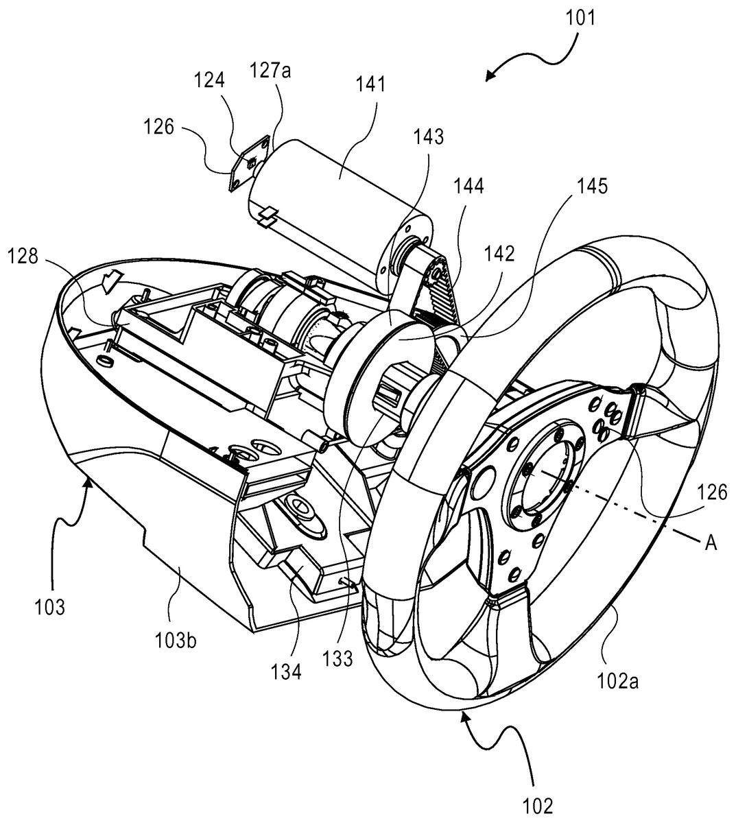
FIG. 7is a view in perspective of a second example of a game controller according to the invention. This controller101comprises an actuator102, in the form of a steering wheel (steering wheel type of a saloon car, for example) mobile in rotation in relation to a fixed part or frame103according to an axis A of rotation, and which can be detached from this fixed part103. The fixed part103can be mounted on a fixed support S through a known system of fastening F, as shown inFIGS. 10A and 10B. The fixed part103comprises, as shown inFIG. 10C, an upper shell103aassembled in a removable manner to a lower shell103band to a front face103c.
The lower shell103bof the fixed part103provides the link or the fastening, whether or not reversible, of the controller101to a support such as a table, a worktop or a cockpit. The game controller101can be associated with pedals and, in the case where the shifting of speeds is not carried out at the steering wheel, to a gearbox separated from the steering wheel.
FIG. 7shows, via a perspective view, the interior of the controller101once the upper shell103aand the front face103care removed in particular.
In this figure can be distinguished a plate134connected in a fixed manner to the fixed part103, the shaft133(which constitutes the steering column of the controller101) to which is connected the actuator102. The shaft133(or steering column133) is integral with the actuator102, and is therefore displaced in rotation around the axis A in the same way as the actuator102.
FIG. 8shows, via a perspective view, the interior of the controller101once the upper shell103a, the front face103cand the lower shell103bare removed in particular.
The rotation of the steering column133is dynamised by a first system, referred to as the torque effect system and, where applicable, for vibration(s), by means, for example, of a rotary electric motor141of which the axis of rotation is more preferably substantially parallel to that of the steering column133. The rotary electric motor141acts on the steering column133by the intermediary of a system of pulleys or toothed wheels and of belts or chains. In the embodiment shown, a toothed belt and toothed wheels are used.
In this case, a toothed wheel142of large diameter (for the precision) is fixed coaxially to the steering column133. This toothed wheel142receives mechanically (via a train of toothed wheels and a toothed belt) the forces exerted by the electric motor141which is actuated according to the torque or vibration effects implemented by the game.
As such, on this toothed wheel142is mounted a toothed belt143connected to a small toothed wheel of the intermediary wheel145. This intermediary wheel145comprises indeed a small toothed wheel (not shown as the intermediary wheel is shown only partially) and a large toothed wheel which are coaxial (the intermediary wheel145forms a single part but it could be formed from two parts fixed together). The large toothed wheel of the intermediary wheel145drives a toothed belt144. This toothed belt144is connected to the shaft of the rotary electric motor141(which dynamises in rotation the shaft133of the actuator102).
The toothed wheel142, and therefore the steering column133and the actuator102, pivots or stops its rotation around the axis A under the action of the electric motor141. For example, it can return the actuator102to neutral position, or oppose the rotation of the steering column133, cause the rotation of the steering column133, cause shakes in the rotation of the steering column133, etc.
Inversely, as the steering column133of the actuator (steering wheel in the case shown)102is connected to the rotary electric motor141via a system of toothed belt and wheel system, a movement of the actuator102is transmitted to the steering column133of the steering wheel and to the shaft (or axis) of the rotary electric motor141.
As such, the system of toothed belts and wheels transmits the rotating movement of the shaft of the steering wheel to the shaft of the rotary electric motor (and reciprocally). In this sense, these shafts are integral in rotation.
Such a torque effect system using a rotary electric motor allows for a return to the centre (here, a return of the actuator102to neutral angular position) which does not limit the number of revolutions that the actuator102can carry out, contrary to what is made possible by a centre return system via elastic or spring(s).
A magnet carrier127a(i.e. a magnet support127a) is mounted integral with the axis or with the shaft of the rotary electric motor141. This magnet carrier127a, and therefore the magnet127b, is mobile in rotation around the axis of rotation of the rotary electric motor141.
A magnetic sensor (a biaxial Hall effect sensor here)124mounted on a PCB126is placed in the vicinity of the magnet carrier127asubstantially in the extension of the axis of the rotary electric motor141.
In other terms, the magnetic sensor124is placed not across from the shaft133of the actuator102as in the first embodiment but across from the shaft of the rotary electric motor141.
Note that the support of the PCB126of the magnetic sensor is not shown inFIGS. 7 and 8, but can be seen inFIG. 12(referenced as180). This support180of the PCB126and the magnetic sensor124are integral with the fixed part of the motor, i.e. with the case or envelope of the electric motor which is fixed by screws to the upper half-shell129of the rotary electric motor141. The support180of the PCB126and the magnetic sensor124are not integral with the fixed part103of the controller101.
As shall be seen in what follows, the rotary electric motor141is driven in translation, with the lower half-shell128and with the upper half-shell (which is not shown), by the linear electric motor in relation to the fixed part103of the controller101. Moreover, the shaft133of the actuator102is mobile in rotation in relation to the lower half-shell128which is mobile in translation, but not in rotation, in relation to the fixed part103of the controller101.
The steering column133, and therefore the steering wheel102, is dynamised in translation by a second system, referred to as a force feedback system.
To do this, the controller102of the game controller101is mounted mobile in translation in relation to the fixed part103according to its axis of rotation A or according to an axis close to (and therefore separate) this axis A, over a predetermined range of displacement, using an assembly of two sliding parts sliding in relation to one another. The displacement in translation of the controller102is controlled by an electromagnetic device190(or linear electric motor) which can be seen partially in FIG.12(the shoe161is concealing it almost entirely), and the same applies to the support180of the PCB126of the magnetic sensor.
More precisely, as shown inFIG. 13, the electromagnetic device190controls the displacement in translation of a guiding body191mobile in relation to the fixed support103and whereon are made integral the steering column133and the actuator102. This guiding body191slides in relation to a guiding plate192which is integral with the fixed part103.
The guiding body191has the form of a base with a substantially parallelepiped shape comprising a slot (or housing) that can be accessed by two rectangular openings located on two opposite faces of the base.
The guiding plate192has the form of a magnet carrier plate which carries at least one magnet (not shown) and comprises a part or penetrating portion51intended to be housed in the housing of the guiding body191, as shown inFIG. 13. This magnet carrier plate192is furthermore integral (here via screwing) with the prongs1341of the plate134and with the two right161and left160shoes. The base of the guiding body191comprises at least one winding (not shown) which, according to the electric signal passing through it, causes the displacement of the base in relation to magnet carrier plate192. It is easily understood that the direction, the travel (or range) and/or the speed of displacement of the base of the guiding body191, and therefore of the steering column133, are according to the electric signal running through the winding or windings. The maximum travel depends on the dimensions of the linear motor used. It is possible to use a linear motor of which the guiding body191is longer in order to obtain an amplitude of relative displacement of the guiding body191that is greater in relation to magnet carrier plate192and therefore a maximum travel of the steering column133that is longer.
Note that in this second preferred embodiment, the steering column133is not horizontal but inclined in relation to the horizontal in order to make it possible to have the user feel the force feedback effect according to four directions (up, down, front, rear) thanks to only an electromagnetic device, a guiding body191and a guiding plate192.
In an alternative embodiment described hereinabove, the guiding body191can be integral with the fixed part103and the guiding plate192can be integral with the actuator102.
In another embodiment, the steering column133can be substantially horizontal.
InFIG. 11, the interior of the controller101can be distinguished once the steering wheel102, the upper shell103a, the lower shell103band the front face103are removed (as well as the paddles125for speed change, the cover174, the bellows175, the stick172with its connector123, and the nut173). The lower128and upper129half-shells are fixed together, for example, by screws.
In order to allow for the translation of the steering column133(and at the same time of the half-shells128,129and of the torque and vibration effect system, implementing the rotary electric motor141in particular), a linear electric motor (the linear electric motor is not shown inFIG. 11, but can be seen inFIG. 13(referenced as190)) comprising two elements, one being mobile in translation in relation to the other according to an electric signal, is implemented. One of the elements of the linear electric motor is fixed to the plate134and to the two right161and left160shoes (which are fixed in relation to the fixed part103) and the other element is fixed to the lower half-shell128, for example by screws.
Moreover, a plate163is fixed to the half-shells128,129, for example by screws, this plate163being mobile in translation but not in rotation. It comprises two roller tensioners162which act on the toothed belt143.
The controller101comprises a system of fastening which makes it possible to fix and to lock reversibly the actuator102to the fixed support103in such a way as to allow for the transmission of the rotating movement of the actuator102towards the steering column which, in this embodiment, is the shaft133.
FIG. 9shows the steering wheel102awhen it is detached from the fixed part103. The steering wheel102acomprises a threaded tip170which comprises a cavity-receptacle171, in the form of a female end, wherein is housed a connector123a, for the supply of electrical energy and/or data transmission. This data corresponds for example to information on the rotation of the actuator102, and where applicable additional information, such as a speed change command, when the user acts on the paddles125(which can be seen inFIG. 10C), or other commands triggered by the activation of buttons126(which can be seen inFIG. 7) located on the actuator102, or where applicable to states to be displayed by indicators, or finally to information on the vibrations (or electric signals corresponding to the vibrations) which must be executed by small vibration systems incorporated into the wheel of the steering wheel102a(such a vibration system comprises a small rotating electric motor and a dissymmetric mass fixed to the shaft of this small motor, in such a way that the centre of gravity of this mass is separated from the axis of rotation of the small rotating electric motor and that this causes an unbalance and therefore vibrations in the wheel of the steering wheel102a).
The other part102bof the actuator102integral with the front face103cof the fixed part103is shown inFIG. 10. It comprises a stick172in the form of a male end which is fixed to the shaft133of the actuator102. A movable ring or nut173of which the inside bore is threaded is placed on the stick172. The nut173is mobile in rotation and in translation as long as it is not screwed, a shoulder of the stick172however forming a stop in translation which prevents the nut173from becoming completely separated from the stick172.
In order to attach the steering wheel102ashown inFIG. 9to the part102bof the actuator102shown inFIG. 10, it is required to push the steering wheel102aagainst the stick172of the steering column or shaft133of the actuator102and to place the male end of the stick172into the female end of the cavity-receptacle171of the tip170of the steering wheel102a. It is then required to turn the nut173in order to screw it onto the screw thread of the threaded tip170of the steering wheel102a. The steering wheel102ais then integral in rotation and in translation with the stick172and therefore with the steering column133.
Of course, it is possible to replace this system of fastening of the steering wheel102awith the system of fastening described in the first preferred embodiment in such a way that the fixed part103uses the system of fastening which makes it possible to fix and to lock reversibly the actuator2onto a linking part31. The actuator2can then be fixed reversibly onto such a fixed part. In this case (if the steering wheel102acomprises electrical elements), the connector123is replaced with a connector23(or with a case of batteries and where applicable a wireless transmission device if signals must be sent or received by the steering wheel102a).
FIG. 10Calso shows a bellows175and a cover174, intended to prevent, or at least limit, the presence of dust and fouling in the fixed part103of the controller101.
The other part102bof the actuator102further comprises a connector123b, with the electric signals being sent via these connectors123a,123bin a bidirectional manner.
The dimensions and the forms of the tip170of the actuator102, of the stick172and of the nut173are selected in such a way that the connectors are not subjected to any substantial forces and, consequently, are not degraded.
Many other means for reversible fastening can of course be implemented, without leaving the scope of the invention, including a simple nesting by force of the steering wheel102aon the steering column133, in a simplified embodiment.
According to a particular embodiment of the invention, the magnetic sensor124provides in real time the data which allow a microprocessor to control in real time the displacement in rotation (and where applicable the displacement in translation), by determining in real time the actual displacement or displacements (the actual travel and the actual angle can be measured directly but it is also possible to determine the actual direction, acceleration and speed of the displacement).
This particular embodiment makes it possible to take into account the consequences caused by the forces exerted by the user on the actuator102(and therefore on the steering column133and on the shaft of the rotary electric motor141which is integral with it) and to adjust the electric signal if required. It allows for a control of the displacement in rotation (and, where applicable, of the displacement in translation). In this particular embodiment, the displacement is therefore controlled.
In the second embodiment shown in particular inFIGS. 7 and 9, the part102aof the actuator comprises buttons126and a connector123a. According to an alternative of the invention, the actuator102amay contain no element controlling or carrying electric currents (in particular no button and no connector). Indeed, the actions which correspond to the buttons can be carried out via one or several devices of the fixed part103, more precisely thanks to one or several control devices. These control devices can, for example, have the form that resembles that of a windscreen wiper control stick and/or that of a turn signal control stick. Moreover, note that the presence of vibration systems incorporated into the wheel of the steering wheel102ais not indispensable as the torque effect system is also able to produce vibrations and this in a more realistic manner. Consequently, according to this alternative, only the fixed part103then comprises elements that control or that carry electric currents (all of the “electrical” elements of the game controller are then grouped together in the fixed part103), contrary to the first preferred embodiment of the invention according to which the actuator2groups together all of the “electrical” elements).
Due to the absence of the need for permanent contact between the actuator2,102and the fixed part3,103, the actuator can easily be changed for another type of actuator. This can be done in coherency with the software and more precisely according to the vehicle simulated by the software, and makes it possible to adapt the ergonomics and the feeling of the various actuators.
For example, the user can easily change an actuator of the steering wheel type to install an actuator of the handlebar type if the video game with which he is playing simulates a motorcycle, instead of a steering wheel mounted beforehand. It is also possible to provide variations of the steering wheel, according to the type of simulated vehicle. For cars, the variations of steering wheel can in particular be: formula 1, saloon, rally, all-terrain, kart, etc. For trains, the variations can be: Micheline, T.G.V., etc. For motorbikes, the variations in handlebars can be: unprepared motorcycle, racing motorcycle, off-road motorcycle, rally motorcycle, scooter, etc. For bicycles, the variations in handlebars can be: racing cycle, hybrid bicycle, mountain bicycle, city bicycle, etc. for boats, the variations in helm wheels can be: galleon wooden helm, helm of a modern sailing ship, fly-wheel, etc. The actuators can therefore have different shapes, different diameters, different buttons in such a way that their ergonomics is adapted to the type of simulated vehicle. They can further comprise motors with different vibrations, they can be wired or wireless (for data transmission), etc.
It is also possible to provide, in a particular embodiment, that the number of revolutions that the actuator can carry out in relation to the fixed part differ according to the type of actuator used or according to the type of fixed part used or according to the range level of the controller. As such, magnetic sensors or different magnets can be provided, according to the actuators, in such a way as to obtain different restored effects, a different resolution (more or less precise displacement measurements), and/or a resistance that is more or less strong to the magnetic disturbances or to the temperature variations, etc.
In the figures, the game controller is shown without a device providing the link with the floor or the reversible or non-reversible fastening with a support such as a table or a worktop or a cockpit. Such devices exist. For example, the game controller can be provided with a device according to U.S. Pat. No. 6,378,826 and in this case, with a fixed part carried out according to the first preferred embodiment, the fixed part and the device do not comprise any element operating thanks to electric currents or to electromagnetic fields and no element that controls or that carries electric currents. More preferably, this device can be separated from the fixed part.
According to another embodiment of the invention, the first embodiment is combined with the second embodiment described hereinabove. In particular, the fixed part3can be modified in such a way that this fixed part comprises the first torque and vibration effect system and the second system, referred to as force feedback system, described in the second preferred embodiment. A first Hall effect or magnetoresistive effect detecting unit can be used to measure the displacement in rotation of the axis of the rotary electric motor141of the torque and vibration effect system. To this effect, a magnetic sensor124mounted on a PCB126can then be placed in the vicinity of the magnet carrier127asubstantially in the extension of the axis of the rotary electric motor141in order to measure the displacement in rotation of the magnet127b. It is also possible to measure the displacement in translation of the steering column:either via a second sensor (placed on a PCB screwed to a support fixed to the shoe or to the upper shell103a) measuring the displacement in translation of the magnet127b(i.e. the displacement in translation of the axis of the rotary electric motor141of the torque and vibration effect system which is integral in translation with the steering column133);or via a second Hall effect or magnetoresistive effect detecting unit measuring the displacement in translation of the steering column (or of another part integral in translation with the steering column).
In such an embodiment, a magnetic sensor on board in the actuator2(intended to cooperate with a magnet37of the fixed part which is placed in the vicinity of the system of fastening) is no longer indispensable as the information pertaining to the measurement of the displacement of the steering column in rotation is then redundant with the information from the first Hall effect or magnetoresistive effect detecting unit. However, the magnetic sensor on board in the actuator makes it possible to detect the presence and the type of fixed part with which cooperates the actuator2(if the fixed part incorporates the first detection unit, then in order to prevent redundancy and save energy, it is possible to automatically deactivate the detection unit on board in the actuator until the reinitialising or the turning back on of the game controller, and to deactivate all of the on-board circuits if the fixed part comprises all of the required commands and if the user has not pressed a button for the activation of the actuator for a predetermined period of time). Furthermore, the presence of the magnetic sensor on board in the actuator renders the actuator2fully compatible with the various types of fixed parts (those that comprise and those that do not comprise a first Hall effect or magnetoresistive effect detecting unit).
Claims
- A game controller having an actuator mobile in rotation in relation to a fixed part, in such a way as to simulate a control of the rotation of a steering column of a simulated vehicle, comprising : at least a motion production system comprising a rotatable part which is mobile in rotation in relation with the fixed part and a non-rotatable part which is not mobile in rotation in relation with the fixed part, the rotatable part of said motion production system and the non-rotatable part of said motion production system being substantially coaxial, wherein said motion production system generates displacement in rotation of the rotatable part in relation to the non-rotatable s part by elasticity or electromagnetism, means for detecting the displacement in rotation of the rotatable part of said motion production system comprising at least one Hall effect or magnetoresistive effect detecting unit, constituted of at least two elements, of which a permanent magnet and a magnetic sensor, in that, at least during the rotation of said actuator, the actuator is integral in rotation with the rotatable part of said motion production system, and in that, at least during the rotation of said actuator, a first of said elements is integral in rotation with said actuator and is fixed in relation to the rotatable part of said motion production system, and in that, at least during the rotation of said actuator, a second of said elements is integral in rotation with said fixed part and is fixed in relation to the non-rotatable part of said motion production system, in such a way both the angular displacement of the rotatable part of said motion production system with respect to the fixed part being identical to the angular displacement of the rotatable part of said motion production system with respect to the non-rotatable part.
- The game controller according to claim 1 , characterised in that at least two of said elements are substantially aligned according to the axis of rotation of said rotatable part of said motion production system, and in that, the actuator and the rotatable part of said motion production system are substantially coaxial.
- The game controller according to claim 1 having at least a rotary electric motor to generate displacement in rotation of the actuator, wherein the rotatable part of said motion production system is a rotor of said rotary electric motor and wherein the non-rotatable part of said motion production system is a stator of said rotary electric motor, characterised in that a first of said at least two elements is fixed to the rotor of said rotary electric motor in such a way said rotor forms at least a part of a carrier carrying the first of said at least two elements, and in that, a second of said at least two elements is located in the vicinity of the first of said at least two elements across from the rotor of the rotary electric motor.
- The game controller according to claim 3 , characterised in that it comprises a steering column and at least one linear electric motor acting on said steering column for displacement in translation of said actuator in relation to said fixed part over a predetermined range of displacement.
- A game controller having an actuator mobile in rotation in relation to a fixed part, in such a way as to simulate a control of the rotation of a steering column of a simulated vehicle, comprising : at least a rotary electric motor to generate displacement in rotation of the actuator, and means for detecting the displacement in rotation of said actuator comprising at least one Hall effect or magnetoresistive effect detecting unit, constituted of at least two elements, of which a permanent magnet and a magnetic sensor, in that, at least during the rotation of said actuator, a first of said elements is integral in rotation with said actuator and a second of said elements is integral in rotation with said fixed part, characterised in that the magnet is fixed to a rotor of said rotary electric motor in such a way said rotor forms at least a part of a carrier carrying the first of said at least two elements, in that, the magnetic sensor is located in the vicinity of the first of said at least two elements across from the rotor of the rotary electric motor, in that said actuator can be detached from a steering column of the game controller by a player, and in that the magnetic sensor is mounted on a support which is integral with the stator of the rotary electric motor, and in that the magnet is at an end of said rotor of said rotary electric motor in such a way said magnet is placed less than 9 mm from the magnetic sensor.
- A game controller having an actuator mobile in rotation in relation to a fixed part, in such a way as to simulate a control of the rotation of a steering column of a simulated vehicle, comprising : means for detecting the displacement in rotation of said actuator comprising at least one Hall effect or magnetoresistive effect detecting unit, constituted of at least two elements, of which a permanent magnet and a magnetic sensor, in that, at least during the rotation of said actuator, a first of said elements is integral in rotation with said actuator and a second of said elements is integral in rotation with said fixed part, and in that, said actuator can be detached from a steering column of the game controller by a player, characterised in that said actuator comprises a housing forming a female part, provided to nest reversibly on a corresponding male part on said fixed part.
- The game controller according to claim 6 , characterised in that a portion of the actuator forming a casing provides the protection of the magnetic sensor.
- A game controller having an actuator mobile in rotation in relation to a fixed part, in such a way as to simulate a control of the rotation of a steering column of a simulated vehicle, comprising : means for detecting the displacement in rotation of said actuator comprising at least one Hall effect or magnetoresistive effect detecting unit, constituted of at least two elements, of which a permanent magnet and a magnetic sensor, in that, at least during the rotation of said actuator, a first of said elements is integral in rotation with said actuator and a second of said elements is integral in rotation with said fixed part, and in that said actuator can be detached from a steering column of the game controller by a player, characterised in that it comprises means for reversibly locking of said actuator onto said fixed part.
- The game controller according to claim 8 , characterised in that said actuator comprises a connector for the supply of electrical energy.
- The game controller according to claim 8 , characterised in that said actuator belongs to the group comprising: steering wheels;handlebars;ship helms.
- The game controller according to claim 8 , characterised in that it comprises or is compatible with at least two interchangeable actuators, each having different forms and/or different commands, in such a way the player can change a first actuator of the game controller to install a second actuator having a different form and/or different commands.
- The game controller of claim 8 further comprising: the actuator mobile in rotation in relation to the fixed part, in such a way as to simulate a control of the rotation of a steering column.
- The game controller of claim 8 further comprising: the fixed part with the actuator mobile in rotation in relation to said fixed part.
- A game controller having an actuator mobile in rotation in relation to a fixed part, in such a way as to simulate a control of the rotation of a steering column of a simulated vehicle, comprising at least one Hall effect or magnetoresistive effect detecting unit for detecting at least the angle of the displacement in rotation of said actuator, characterised in that the Hall effect or magnetoresistive effect detecting unit is constituted of at least two elements, of which a magnet and a multiaxis magnetic sensor sensing the characteristics of the magnetic field of the magnet according to at least two directions, in that, at least during the rotation of said actuator, a first of said elements is integral in rotation with said actuator and a second of said elements is integral in rotation with said fixed part, in that the game controller comprises at least one of a center return system and an electric motor, said at least one of an electric motor and of a said center return system being centred on and symmetrical with respect to the axis of rotation of the actuator and, said at least one of an electric motor and of a said center return system guiding one of said at least two elements in relation to the axis of rotation of said actuator, in such a way this element being substantially recentred according to the axis of rotation of said electric motor or center return system and said multiaxis magnetic sensor detecting at least the angle of rotation of the magnet in relation to the said multiaxis magnetic sensor.
- The game controller according to claim 14 characterised in that a shaft of said electric motor or a shaft of said center return system is fixed to said fixed part.
- The game controller according to claim 15 characterised in that it comprises a steering column mobile in rotation around said shaft.
- The game controller according to claim 14 characterised in that it comprises a steering column and in that said electric motor or center return system is a part of said steering column.
- A game controller having an actuator and a shaft which are mobile in rotation in relation to a fixed part, in such a way as to simulate a control of the rotation of a steering column of a simulated vehicle, and at least one Hall effect or magnetoresistive effect detecting unit for detecting at least the angle of the displacement in rotation of said actuator, wherein the Hall effect or magnetoresistive effect detecting unit is constituted of at least two elements, of which a magnet and a magnetic sensor, characterised in that a linear electric motor acting between a housing and the fixed part drives both said shaft and said housing in translation in relation to said fixed part, in that said shaft is mobile in rotation in relation to said housing, in that said housing is mobile in translation, but not in rotation, in relation to said fixed part, in that, at least during the rotation of said actuator, a first of said elements is integral in rotation with said actuator and a second of said elements is integral in rotation with said fixed part.
- The game controller according to claim 18 characterised in that it comprises a sensor for detecting at least the displacement in translation of said shaft.
- The game controller according to claim 18 characterised in that the actuator is reversibly attached to the fixed part in such a way that it can be detached by a user.
- The game controller according to claim 18 characterised in that it comprises a rotary electric motor acting on the actuator.
- A game controller having an actuator mobile in rotation in relation to a fixed part, in such a way as to simulate a control of the rotation of a steering column of a simulated vehicle, comprising : means for detecting the displacement in rotation of said actuator comprising at least one Hall effect or magnetoresistive effect detecting unit, constituted of at least two elements, of which a permanent magnet and a magnetic sensor, in that, at least during the rotation of said actuator, a first of said elements is integral in rotation with said actuator and a second of said elements is integral in rotation with said fixed part, in that, a fixed magnet carrier extending substantially according to the axis of rotation of said actuator is fixed to said fixed part, and in that, at least one of said elements is carried and fixed to said fixed magnet carrier.
- The game controller according to claim 22 , characterised in that said fixed magnet carrier penetrates in a mobile part which is mobile in rotation around said fixed magnet carrier according to the axis of rotation of said actuator.
- The game controller according to claim 23 , characterised in that said magnetic sensor is in said actuator, and in that said magnet carrier is a rod which carries said magnet in such a way that said magnet penetrates in said mobile part and is placed less than 9 mm from said magnetic sensor.
Disclaimer: Data collected from the USPTO and may be malformed, incomplete, and/or otherwise inaccurate.