U.S. Pat. No. 8,913,664
THREE-DIMENSIONAL MOTION MAPPING FOR CLOUD GAMING
AssigneeSony Computer Entertainment Inc.
Issue DateSeptember 16, 2011
Illustrative Figure
Abstract
Three-dimensional motion mapping is disclosed. A reverse three-dimensional transform for a set of anchor pixels in the current frame is performed using a model-view matrix, a projection matrix, and view parameters associated with the computer game. Reverse transformed anchor pixels are indicated as occluded if the estimated depth for the pixel in the previous frame is greater than a real depth for the pixel in the previous frame or otherwise indicated as visible. A motion vector map for a subset of the reverse transformed pixels is constructed. A best target motion vector for a first set of sections in the current frame is derived or motion estimation is performed for sections in a second set that contain occluded pixels. Target motion vectors for groups of two or more sections of the current frame comprising two or more adjoining sections each with best target motion vectors are derived.
Description
DESCRIPTION OF THE SPECIFIC EMBODIMENTS Although the following detailed description contains many specific details for the purposes of illustration, anyone of ordinary skill in the art will appreciate that many variations and alterations to the following details are within the scope of the invention. Accordingly, the exemplary embodiments of the invention described below are set forth without any loss of generality to, and without imposing limitations upon, the claimed invention. Embodiments of this invention provide a new approach for improving latency issues associated with cloud gaming systems. Instead of further optimizing the traditional motion search algorithm with more powerful CPU-based single instruction multiple data (SIMD) instructions, latency can be reduced by bridging both processing engines (e.g., game engine and video engine) using geometric information to potentially reduce or replace motion search. This approach proposes to utilize intermediate results and geometric information from a pipelined game engine, so that the motion vector can be constructed quickly and precisely, thereby significantly reducing processing delays. By way of example, as see inFIG. 1A, in a cloud-based video game a server10and client20are connected via a network30. The network30may be any suitable computer/telecommunications network, e.g., Ethernet, WiFi, 3G, 4G, internet protocol (IP) networks. A video game typically generates a set of video sequences that depict various environments to facilitate interaction with a user. At the client20a user's interactions with the game environments are typically received in the form of commands from some sort of interface21, e.g., a joystick, motion sensor, video camera, microphone array or other input device. Data representing these interactions are transmitted over the network30to the server10, which interprets the interaction data and later the interpreted interaction data can be used by a game engine11to perform desired operations. The interaction data may include the locations and movements of objects (including, but not limited ...
DESCRIPTION OF THE SPECIFIC EMBODIMENTS
Although the following detailed description contains many specific details for the purposes of illustration, anyone of ordinary skill in the art will appreciate that many variations and alterations to the following details are within the scope of the invention. Accordingly, the exemplary embodiments of the invention described below are set forth without any loss of generality to, and without imposing limitations upon, the claimed invention.
Embodiments of this invention provide a new approach for improving latency issues associated with cloud gaming systems. Instead of further optimizing the traditional motion search algorithm with more powerful CPU-based single instruction multiple data (SIMD) instructions, latency can be reduced by bridging both processing engines (e.g., game engine and video engine) using geometric information to potentially reduce or replace motion search. This approach proposes to utilize intermediate results and geometric information from a pipelined game engine, so that the motion vector can be constructed quickly and precisely, thereby significantly reducing processing delays.
By way of example, as see inFIG. 1A, in a cloud-based video game a server10and client20are connected via a network30. The network30may be any suitable computer/telecommunications network, e.g., Ethernet, WiFi, 3G, 4G, internet protocol (IP) networks.
A video game typically generates a set of video sequences that depict various environments to facilitate interaction with a user. At the client20a user's interactions with the game environments are typically received in the form of commands from some sort of interface21, e.g., a joystick, motion sensor, video camera, microphone array or other input device. Data representing these interactions are transmitted over the network30to the server10, which interprets the interaction data and later the interpreted interaction data can be used by a game engine11to perform desired operations. The interaction data may include the locations and movements of objects (including, but not limited to, player characters or avatars) in a game environment. The game engine11takes into account the locations and movements of objects within the game environments and applies a set of rules for interactions involving these objects.
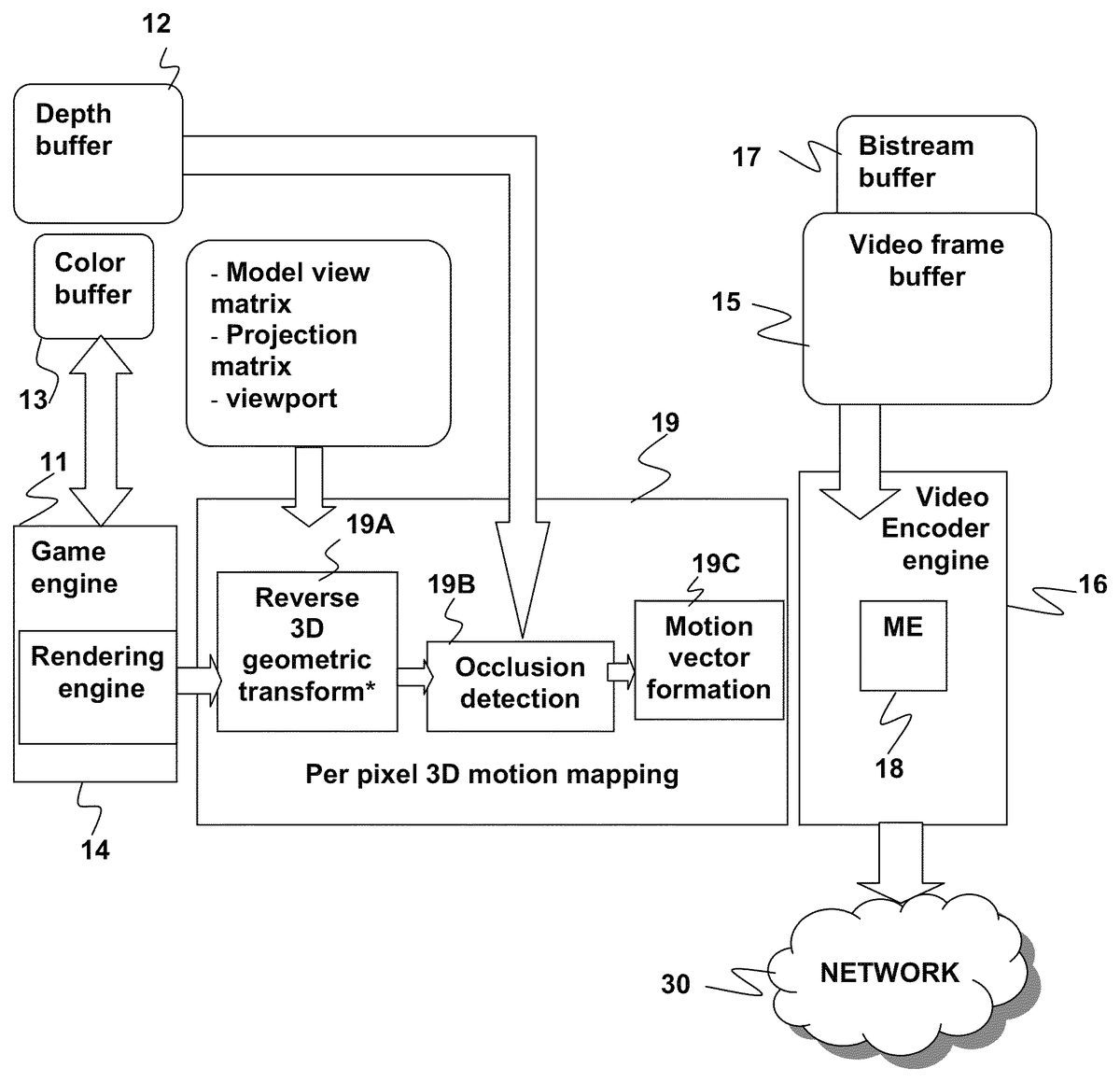
The game engine11can typically keep track of the locations of objects in three dimensions. Depth information for objects is stored in a depth buffer12and color information is stored in a color buffer13. The game engine11may include a rendering engine14that can generate a video image depicting a scene of the environment. The rendering engine14may determine a virtual camera position from which the three dimensional environment is to be viewed and generate a corresponding video frame, e.g., using information from the depth buffer12and color buffer13. The rendering engine14may use other information or results in addition to information from the depth buffer12and color buffer13, such as lighting source information generated by the game engine11, to generate the video frame. By repeating this process at regular intervals (or on an as needed basis), the game engine11can produce video sequences made up of individual video frames, which may be temporarily stored in a video frame buffer15. It is noted that, the process can be repeated at irregular intervals. For example, for video game contents, it is very likely for there to be no object movement or content change for two or more frames. In this case, it is not necessary to encode those duplicated frames. Instead, the repeated frame may be encoded once and send out. Each video frame may be partitioned into several different segments in order to facilitate processing (e.g., rendering, encoding, decoding, etc.). The data for video image is compressed and encoded by a video encoder engine16to form a bitstream, which may be stored in a bitstream buffer17before it is transmitted over the network30. Part of the encoder engine16is a motion estimator18, which compresses the video frame data by encoding differences between a current frame and a previous frame.
At the client20, the bitstream may be temporarily stored in a bitstream buffer22before being sent to a video decoder engine23that decodes the bitstream to video image data. The video image data may be temporarily stored in a video frame buffer24before it is presented on a display25.
FIG. 1Bis a schematic diagram illustrating an example of a partitioning scheme for a video frame in accordance with an embodiment of the present invention. By way of example, and not by way of limitation, as shown inFIG. 1B, a single picture100(e.g., a digital video frame) may be broken down into one or more sections. As used herein, the term “section” can refer to a group of one or more pixels within the picture100. A section can range from a single pixel within the picture, up to the whole picture. Non-limiting examples of sections include slices102, macroblocks104, sub-macroblocks106, blocks108and individual pixels110. As illustrated inFIG. 1A, each slice102contains one or more rows of macroblocks104or portions of one or more such rows. The number of macroblocks in a row depends on the size of the macroblocks and the size and resolution of the picture100. For example, if each macroblock contains sixteen by sixteen pixels then the number of macroblocks in each row may be determined by dividing the width of the picture100(in pixels) by sixteen. Each macroblock104may be broken down into a number of sub-macroblocks106. Each sub-macroblock106may be broken down into a number of blocks108and each block may contain a number of pixels110. By way of example, and without limitation of the invention, in a common video coding scheme, each macroblock104may be broken down into four sub-macroblocks106. Each sub-macroblock may be broken down into four blocks108and each block may contain a four by four arrangement of sixteen pixels110.
FIGS. 2A-2Dillustrate a method for 3-D motion mapping of video frames that may be used in the context of cloud gaming. As seen inFIG. 2A, the server10may be modified to include a 3D motion mapping engine19that implements reverse 3D geometric transformation19A, occlusion detection19B and motion vector formation19C. These processes can be understood with reference toFIG. 2B,FIG. 2C, andFIG. 2D.
It is noted that it is not necessary to do 3D motion mapping for every pixel, although it is within the scope of embodiments of the present invention to do so. To further speed up the mapping, the server can selectively pick some “anchor” pixels within each video frame and perform the reverse 3D geometric transformation19A to generate reverse transformed anchor pixels. Occlusion detection19B and motion vector formation19C may then be performed only on the resulting reverse transformed anchor pixels without significantly degrading the search results. By way of example, and not by way of limitation, the server10may choose every other pixel in a frame in both the vertical and horizontal directions as anchor pixels. This would reduce by three-quarters the number of pixels for which 3D motion mapping is done. The anchor pixels may be chosen in any suitable fashion, e.g., they may be selected according to some other pattern or even randomly selected. Embodiments of the invention are not limited by the fashion in which the anchor pixels are chosen.
FIG. 2Bis a flow diagram illustrating a method200of 3-D motion mapping of a video according to an embodiment of the present invention.FIG. 2Cis a flow diagram detailing the steps200′ of 3-D reverse three-dimensional transformation fromFIG. 2Baccording to an embodiment of the present invention.FIG. 2Dis a schematic diagram illustrating the steps of 3-D reverse transformation fromFIG. 2Caccording to an embodiment of the present invention.
Referring toFIG. 2B, a current video frame in a sequence of video frames undergoes 3-D motion mapping. Initially, a reverse three-dimensional transform19A is performed for a set of pixels (e.g., a set of anchor pixels, as discussed above) in the current frame as indicated at201. The set of pixels may include all pixels in the current frame or some subset of all pixels, e.g., every other pixel in the vertical and horizontal direction or some other subset of pixels at different locations in the current frame. The reverse three-dimensional transform is performed in order to establish a relationship between pixels in the current video frame and pixels in a previous video frame. The reverse three-dimensional transform involves several steps, which are depicted as a second flow diagram inFIG. 2C.FIG. 2Cis supplemented byFIG. 2D, which provides a schematic diagram detailing the steps for performing a reverse three-dimensional transform.
Referring now toFIG. 2Cand the steps for performing a reverse three-dimensional transform, for a given pixel in a video frame, the two-dimensional window coordinates associated with the pixel are first mapped to 3-D object coordinates associated with the pixel as described at215. This is illustrated inFIG. 2C, with a first pixel denoted by 2-D window coordinates: P1(xw,yw)tbeing mapped to its 3-D object coordinates: P1(xo,yo,zo)t. The subscript “w” is used to denote window coordinates and the subscript “o” is used to denote object coordinates. The superscript “t” is used to denote the current frame. The 2-D window coordinates may be mapped to 3-D object coordinates using a model-view matrix, a projection matrix, and view parameters associated with the computer game.
The model-view matrix is a matrix representing the current transformation, as determined by the various translations, rotations and scaling operations. Basically model-view matrix describes the change of position, orientation, and scaling of the object in 3-D space.
The projection matrix is a matrix representing the way in which an object in 3-D space is viewed in 2-D space. An example of such a projection is shown in the right-hand side ofFIG. 2D, where P1(X0,Y0,Z0)t−1in 3D space is projected to P1(Xw,Yw)t−1in 2D space.
The mapping may be done by first normalizing the object coordinates and then multiplying a vector representing the normalized object coordinates by the matrix product of the inverse of the model-view matrix with the projection matrix. By way of example, and not by way of limitation, in OpenGL, the gluUnProject( ) API may be used to perform this mapping of the 2-D window coordinates to 3-D object coordinates.
The view parameters specify the location and dimensions of rectangular windows on the screen for displaying a portion of the image/video contents. The rectangular windows are called a “view ports”. The view parameters typically include four values that specify the location and size of a window showing the contents on a screen. The window may be a full screen or some rectangular portion of the full screen. By way of example, and not by way of limitation, a view port may be represented in OpenGL as (x, y, width, and height) in, where (x,y) refer to the location of lower left corner of the viewport rectangle and width, height refer to the width and height of the window.
After the 2-D window coordinates of a pixel in the current frame has been mapped to its 3-D object coordinates, a real depth for the resulting reverse transformed pixel is recorded as described at217. This real depth will be subsequently used to facilitate occlusion detection19B, which is discussed in further detail below. It is noted that the term “real depth” is used to distinguish the depth for the pixel in the current from an “estimated depth”, which is described below.
The 3-D object coordinates associated with a reverse transformed pixel in the current frame are then transformed into 3-D object coordinates associated with a pixel in a previous frame as described at219. This is illustrated inFIG. 2D, with the 3-D object coordinates of the first pixel in the current frame: P1(xo,yo,zo)tbeing transformed into 3-D object coordinates of a first pixel in a previous frame: P1(xo,yo,zo)t−1. The superscript “t−1” is used to denote the previous frame, i.e., the frame preceding the current frame “t”. Viewport Vtrefers to the viewport for the current video frame and viewport Vt−1refers to the viewport for the previous video frame. The 3-D object coordinates of the pixel in the current frame may be mapped to 3-D object coordinates of a pixel in a previous frame using the model-view matrix, the projection matrix, and the view parameters associated with the computer game.
After the 3-D object coordinates of the pixel in the current frame have been transformed into 3-D object coordinates of a first pixel in a previous frame, an estimated depth for the pixel in the previous frame is derived as described at221. The estimated depth of the pixel in the previous frame will be subsequently used to facilitate occlusion detection, which will be discussed in further detail below.
The 3-D object coordinates associated with the pixel in the previous frame are then mapped into 2-D window coordinates associated with the pixel in the previous frames as described at223. This is illustrated inFIG. 2C, with the 3-D object coordinates of the first pixel in the previous frame: P1(xo,yo,zo)t−1being mapped into 2-D window coordinates of the first pixel in the previous frame: P1(xw,yw)t−1. The 3-D object coordinates of the pixel in the previous frame may be mapped to 2-D window coordinates using the model-view matrix, the projection matrix, and view parameters associated with the computer game. After a pixel in the current frame has undergone reverse three-dimensional transform, the model-view matrix, the projection matrix, and the view parameters are updated accordingly.
This concludes the process of performing a reverse three-dimensional transform. The entire process can be summarized mathematically as follows: 2D(xwt,ywt)→3D(x0t,y0t,z0t)→3D(x0t−1,y0t−1,zwt−1)→2D(xwt−1,ywt−1). The three-dimensional transform provides the video encoder engine16, specifically the motion estimator18, with critical information indicating relationships between pixels in a current frame and pixels in a previous frame that are used to simplify and speed up a subsequent encoding process.
A second pixel with window coordinates P2(xw,yw)talso undergoes a reverse three-dimensional transform. The reverse three-dimensional transform generates 2-D window coordinates for the second pixel in the previous frame (P2(xw,yw)t−1).
After the reverse three-dimensional transform19A is completed, occlusion detection19B is performed for each pixel in the current video frame. A pixel is occluded if the estimated depth of the pixel in the previous frame is greater than a real depth for the pixel in the previous frame as indicated at203. A pixel is visible if the estimated depth of the pixel in the previous frame is less than a real depth for the pixel in the previous frame as indicated at203. To determine whether the 2-D window coordinates of the first pixel in the previous frame (P1(xw,yw)t−1) are occluded, two parameters, a real depth for the first pixel in the previous frame (Dt−1) and an estimated depth for the first pixel in the previous frame (dt−1) are compared.
InFIG. 2D, the first pixel in the current frame is successfully transformed back to its position in the previous frame. However, the second pixel in the current frame, when mapped back to its position in the previous frame, is occluded, as indicated by the dashed dot. Once occlusion detection has been completed for each pixel in the current frame, a complete per pixel motion vector map is constructed for the current frame as indicated at205. For a pixel that is successfully transformed back to its position in the previous frame (i.e., visible), its motion vector can be calculated as the difference between the 2-D window coordinates of the pixel in the current frame (P(xw,yw)t) and the 2-D window coordinates of the pixel in the previous frame (P(xw,yw)t−1). However for a pixel that is unsuccessfully transformed back to its position in the previous frame (i.e., occluded), regular motion estimation must be performed in order to calculate a motion vector for the pixel in the current frame.
A best target motion vector may be derived for each section in a first set of sections in the current frame using motion vector map or motion estimation may be performed for each section in a second set of sections in the current frame that include occluded pixels using the motion vector map.
It is noted that it is not necessary to do motion vector mapping for each pixel in the frame or even for each reverse transformed pixel corresponding to an anchor pixel for which reverse 3D transformation was. However, the reverse transform pixels generated by the reverse 3D transform are a superset of those pixels for which the motion vector mapping is done. In other words, in the motion vector map can be generated using some or all the reverse transformed “anchor” pixels that were generated as a result of performing the reverse 3D transform on the “anchor” pixels.
By way of example, and not by way of limitation, the individual pixels may then be grouped into sub-blocks (4×4 block of pixels) in order to form a common motion vector for that group of pixels. A best target motion vector may be derived for each section (e.g., each sub-block of pixels) in the current frame with a majority of visible pixels as indicated at207. By way of example, and not by way of limitation, the best target motion vector MV for a 4×4 sub-block may be derived using the following criteria:
min{∑i=0i=15[λ·R(mvi-MV)+(Dist{Pit-Pit-1|MV})]},
wherein mvirefers to an individual pixel motion vector, R is the rate in bits to encoder the motion vector difference, Dist denotes the distortion, which can be represented, for example, in absolute difference and λ refers to a Lagrange parameter which is used to optimize the cost function, as shown above. It is common to include the value of λ in the cost function to find out the rate distortion optimal solution.
This step essentially minimizes the cost for encoding the motion vector and the distortion given the target motion vector MV. For each sub-block of pixels in the current frame with a majority of occluded pixels, motion estimation may be performed in order to derive a corresponding best target motion vector as indicated at209.
Sections may be grouped into larger a group involving multiple sections in order to form a target motion vector for the group. For example, sub-blocks may then be grouped into sub-macroblocks (8×8 block of pixels) in order to form a target motion vector for that group of pixels as indicated at211. A target motion vector for a sub-macroblock may be derived from its descendant 4 sub-block best target motion vectors based on the following criteria:
min{∑i=0i=3[λ·R(mvi-MV)+(Dist{Pit-Pit-1|MV})]}.
Sub-macroblocks may be further grouped into macroblocks (16×16 block of pixels) in order to form a target motion vector for that group of pixels as indicated at211. In a similar fashion to the formation of a target motion vector for a sub-macroblock, the target motion vector for a macroblock may be derived from its descendant 4 sub-macroblock target motion vectors. The grouping of pixels in a hierarchical manner is known as a pyramid scheme.
Finally, the current frame may be encoded as indicated at213. The current frame will be encoded using the derived best target motion vectors and target motion vectors in order to simplify the complexity of the encoding procedure. By associating pixels in a current frame with corresponding pixels in a previous frame, motion estimation may be significantly avoided during the encoding process, saving processing time and minimizing latency.
FIG. 3illustrates a block diagram of a computer apparatus300that may be used to implement the method for three-dimensional motion mapping described above. The apparatus300generally may include a processor module301and a memory302. The processor module301may include one or more processor cores. In some cases, each processor core in the module301may have a dedicated local memory (not shown).
The memory302may be in the form of an integrated circuit, e.g., RAM, DRAM, ROM, and the like. The memory may also be a main memory that is accessible by all of the processor modules301. In some embodiments, the processor module301may include local memories associated with each core. A program303may be stored in the main memory302in the form of processor readable instructions that can be executed on the processor modules. The program303may be configured to perform three-dimensional motion mapping as described above with respect toFIGS. 2A and 2B. The program303may be written in any suitable processor readable language, e.g., C, C++, JAVA, Assembly, MATLAB, FORTRAN and a number of other processor readable languages. Data307may be stored in the memory302. Such data may include 2-D window coordinates, 3-D object coordinates, estimated depth information, actual depth information, model view matrices, projection matrices, and view parameters. During execution of the program303, portions of program code and/or data307may be loaded into the memory302or the local stores of processor cores for parallel processing by multiple processor cores. The data307may also include rendered video frames or encoded bitstreams, which may be stored in suitably configured buffers. The program may also be configured to implement the functions of the game engine11and video encoder engine16, e.g., as described above.
The apparatus300may also include well-known support functions310, such as input/output (I/O) elements311, power supplies (P/S)312, a clock (CLK)313and cache314. The apparatus300may optionally include a mass storage device315such as a disk drive, CD-ROM drive, tape drive, or the like to store programs and/or data. The device300may also optionally include a display unit316and user interface unit318to facilitate interaction between the apparatus300and a user. The display unit316may be in the form of a cathode ray tube (CRT) or flat panel screen that displays text, numerals, graphical symbols or images. The user interface318may include a keyboard, mouse, joystick, light pen or other device that may be used in conjunction with a graphical user interface (GUI). The apparatus300may also include a network interface320to enable the device to communicate with other devices over a network, such as the internet. These components may be implemented in hardware, software or firmware or some combination of two or more of these.
According to another embodiment, instructions for carrying out three-dimensional motion mapping as described above may be stored in a computer readable storage medium. By way of example, and not by way of limitation,FIG. 4illustrates an example of a computer-readable storage medium400. The storage medium contains computer-readable instructions stored in a format that can be retrieved and interpreted by a computer processing device. By way of example, and not by way of limitation, the computer-readable storage medium400may be a computer-readable memory, such as random access memory (RAM) or read only memory (ROM), a computer readable storage disk for a fixed disk drive (e.g., a hard disk drive), or a removable disk drive. In addition, the computer-readable storage medium400may be a flash memory device, a computer-readable tape, a CD-ROM, a DVD-ROM, a Blu-ray, HD-DVD, UMD, or other optical storage medium.
The storage medium400contains instructions for three-dimensional motion mapping401configured to implement a method of three-dimensional motion mapping in accordance with the method described above with respect toFIGS. 2A-2D. The storage medium400may optionally contain reverse three-dimensional transform instruction403that are used to perform a reverse three-dimensional transform for each pixel in a current video frame of a video game. For each pixel in a current video frame, the reverse three-dimensional transform instructions403may involve: mapping two-dimensional window coordinates associated with the pixel in the current frame to three-dimensional object coordinates associated with the pixel in the current frame; recording a real depth for the pixel in the current frame; transforming the three-dimensional object coordinates associated with the pixel in the current frame into three-dimensional object coordinates associated with a pixel in a previous frame; deriving an estimated depth for the pixel in the previous frame; mapping the three-dimensional object coordinates associated with the pixel in the previous frame to two-dimensional window coordinates associated with the pixel in the previous frame; and indicating that the pixel in the current frame is occluded if the estimated depth for the pixel in the previous frame is greater than a real depth for the pixel in the previous frame, otherwise indicating that the pixel in the current frame is visible.
The instructions for three-dimensional motion mapping401may also include constructing vector map instructions405that are used to construct a per pixel motion vector map for the current frame using the information derived from implementing the reverse three-dimensional transform instructions403.
The instructions for three-dimensional motion mapping401may also include deriving sub-block best target motion vector instructions407that are used to derive a best target motion vector for each sub-block of pixels in the current frame with a majority of visible pixels. As discussed above, a pixel is considered visible if the estimated depth for the pixel in the previous frame is less than a real depth for the pixel in the previous frame.
The instructions for three-dimensional motion mapping401may also include performing motion estimation instructions409that are used to perform motion estimation for each sub-block of pixels in the current frame with a majority of occluded pixels. As discussed above, a pixel is considered occluded if the estimated depth for the pixel in the previous frame is greater than a real depth for the pixel in the previous frame.
The instructions for three-dimensional motion mapping401may further include deriving target motion vector instructions411that are used to derive target motion vectors for macroblocks or sub-macroblocks of the current frame comprising two or more adjoining sub-blocks each with best target motion vectors.
The instructions for three-dimensional motion mapping401may additionally include encoding video frame instructions413that are used to encode the current frame using the target motion vectors, best target motion vectors, and motion estimation results.
While the above is a complete description of the preferred embodiment of the present invention, it is possible to use various alternatives, modifications, and equivalents. Therefore, the scope of the present invention should be determined not with reference to the above description, but should, instead be determined with reference to the appended claims, along with their full scope of equivalents. Any feature described here, whether preferred or not, may be combined with any other feature described herein, whether preferred or not. In the claims that follow, the indefinite article “A” or “An” refers to a quantity of one or more of the item following the article, except where expressly stated otherwise. The appended claims are not to be interpreted as including means-plus-function limitations, unless such a limitation is explicitly received in a given claim using the phrase “means for”.
Claims
- A method for three-dimensional motion mapping in video encoding, comprising: a) performing a reverse three-dimensional transform for a set of anchor pixels in a current frame of video, thereby producing a set of reverse transformed anchor pixels by mapping two-dimensional coordinates associated with a pixel in the current frame to three-dimensional object coordinates, transforming the three-dimensional object coordinates into three-dimensional object coordinates associated with a corresponding pixel in a previous frame, and mapping the three-dimensional object coordinates associated with the corresponding pixel in the previous frame to two-dimensional coordinates associated with the corresponding pixel in a previous frame;b) for each reverse transformed anchor pixel, indicating whether the reverse transformed anchor pixel is occluded or visible, whereby the reverse transformed anchor pixel is indicated as occluded if an estimated depth for a corresponding pixel in a previous frame is greater than a real depth for the corresponding pixel in the previous frame, and whereby the reverse transformed anchor pixel is indicated as not occluded and therefore visible if the estimated depth for the corresponding pixel in the previous frame is not greater than a real depth for the corresponding pixel in the previous frame;c) constructing a motion vector map for at least a subset of the set of reverse transformed anchor pixels;d) deriving a best target motion vector for each section in a first set of sections in the current frame using the motion vector map or performing motion estimation for each section in a second set of sections in the current frame using the motion vector map, wherein the sections in the second set include occluded pixels;e) deriving target motion vectors for one or more groups of two or more sections of the current frame, each group comprising two or more adjoining sections each with best target motion vectors;and f) encoding the current frame using the target motion vectors, the best target motion vector for each section, or motion estimation results.
- The method of claim 1 , wherein the performing the reverse three-dimensional transform includes: deriving the estimated depth for the pixel in the previous frame.
- The method of claim 1 , wherein mapping the two-dimensional window coordinates associated with the pixel in the current frame to three-dimensional object coordinates associated with the pixel in the current frame involves using a model-view matrix, a projection matrix, and view parameters associated with the computer game.
- The method of claim 1 , wherein transforming the three-dimensional object coordinates associated with the pixel in the current frame into three-dimensional object coordinates associated with the pixel in the previous frame involves using a model-view matrix, a projection matrix, and view parameters associated with the computer game.
- The method of claim 1 , wherein mapping the three-dimensional object coordinates associated with the pixel in the previous frame to two-dimensional window coordinates associated with the pixel in the previous frame involves using a model-view matrix, a projection matrix, and view parameters associated with the video game.
- The method of claim 1 , wherein performing the three-dimensional transform further comprises updating a model-view matrix, a projection matrix, and view parameters.
- The method of claim 1 , wherein constructing the complete per pixel motion vector map involves determining a motion vector for each pixel in the current frame by calculating the difference between the 2-D window coordinates of the pixel in the current frame and the 2-D window coordinates of the pixel in the previous frame for a visible pixel or performing regular motion estimation for an occluded pixel.
- The method of claim 1 , wherein each section is a 4×4 array of pixels.
- The method of claim 1 , wherein each group of two or more sections is an 8×8 array of pixels.
- The method of claim 1 , wherein each group of two or more sections is a 16×16 array of pixels.
- The method of claim 1 , wherein deriving target motion vectors in e) involves using a pyramid motion vector formation.
- The method of claim 1 , wherein deriving the best target motion vector includes minimizing a cost for encoding a motion vector and a distortion given a target motion vector.
- The method of claim 1 , wherein d) includes deriving the best target motion vector for each section in the current frame with a majority of visible pixels or performing motion estimation for each section of pixels in the current frame with a majority of occluded pixels.
- A system for implementing three-dimensional motion mapping, comprising: a processor;a memory;and computer-coded instructions embodied in the memory and executable by the processor, wherein the computer coded instructions are configured to implement a method for three-dimensional motion mapping of a current frame of a video game, the method comprising: a) performing a reverse three-dimensional transform for a set of anchor pixels in a current frame of video, thereby producing a set of transformed anchor pixels by mapping two-dimensional coordinates associated with a pixel in the current frame to three-dimensional object coordinates, transforming the three-dimensional object coordinates into three-dimensional object coordinates associated with a corresponding pixel in a previous frame, and mapping the three-dimensional object coordinates associated with the corresponding pixel in the previous frame to two-dimensional coordinates associated with the corresponding pixel in a previous frame;b) for each reverse transformed anchor pixel, indicating whether the reverse transformed anchor pixel is occluded or visible, whereby the reverse transformed anchor pixel is indicated as occluded if an estimated depth for a corresponding pixel in a previous frame is greater than a real depth for the corresponding pixel in the previous frame, and whereby the reverse transformed anchor pixel is indicated as not occluded and therefore visible if the estimated depth for the corresponding pixel in the previous frame is not greater than a real depth for the corresponding pixel in the previous frame;c) constructing a motion vector map for at least a subset of the set of reverse transformed anchor pixels;d) deriving a best target motion vector for each section in a first set of sections in the current frame using the motion vector map or performing motion estimation for each section in a second set of sections in the current frame using the motion vector map, wherein the sections in the second set include occluded pixels;e) deriving target motion vectors for one or more groups of two or more sections of the current frame, each group comprising two or more adjoining sections each with best target motion vectors;and f) encoding the current frame using the target motion vectors, the best target motion vector for each section, or motion estimation results.
- The method of claim 14 , wherein the performing the reverse three-dimensional transform includes: deriving the estimated depth for the pixel in the previous frame.
- A computer program product comprising: a non-transitory, computer-readable storage medium having computer readable program code embodied in said medium for implementing a method for three-dimensional motion mapping of a current video frame in a computer game, the method comprising: a) performing a reverse three-dimensional transform for a set of anchor pixels in a current frame of video, thereby producing a set of transformed anchor pixels by mapping two-dimensional coordinates associated with a pixel in the current frame to three-dimensional object coordinates, transforming the three-dimensional object coordinates into three-dimensional object coordinates associated with a corresponding pixel in a previous frame, and mapping the three-dimensional object coordinates associated with the corresponding pixel in the previous frame to two-dimensional coordinates associated with the corresponding pixel in a previous frame;b) for each reverse transformed anchor pixel, indicating whether the reverse transformed anchor pixel is occluded or visible, whereby the reverse transformed anchor pixel is indicated as occluded if an estimated depth for a corresponding pixel in a previous frame is greater than a real depth for the corresponding pixel in the previous frame, and whereby the reverse transformed anchor pixel is indicated as not occluded and therefore visible if the estimated depth for the corresponding pixel in the previous frame is not greater than a real depth for the corresponding pixel in the previous frame;c) constructing a motion vector map for at least a subset of the set of reverse transformed anchor pixels;d) deriving a best target motion vector for each section in a first set of sections in the current frame using the motion vector map or performing motion estimation for each section in a second set of sections in the current frame using the motion vector map, wherein the sections in the second set include occluded pixels;e) deriving target motion vectors for one or more groups of two or more sections of the current frame, each group comprising two or more adjoining sections each with best target motion vectors;and f) encoding the current frame using the target motion vectors, the best target motion vector for each section, or motion estimation results.
- The computer program product of claim 16 , wherein the performing the reverse three-dimensional transform includes: deriving the estimated depth for the pixel in the previous frame.
Disclaimer: Data collected from the USPTO and may be malformed, incomplete, and/or otherwise inaccurate.