U.S. Pat. No. 8,882,594
CONTROL SCHEME FOR REAL TIME STRATEGY GAME
AssigneeMicrosoft Corp.
Issue DateApril 5, 2007
U.S. Patent No. 8,882,594: Control scheme for real time strategy game
U.S. Patent No. 8,882,594: Control Scheme for real time strategy game
Issued November 11, 2014, to Microsoft Corp.
Priority Date April 5, 2007
Summary:
Real-time strategy games allow the player to command an army against imposing forces in real time. The player builds his army at the same time his opponent. The classic example of a real-time strategy game is StarCraft. Every movement in a real-time strategy game is crucial because time is a factor; wasteful motion can be the difference between winning and losing. Because time is such a factor, PC has dominated the real-time genre due to the flexibility and quickness of a mouse and keyboard offer. Traditionally, the cursor and screen position moved independently of each other. Early attempts at bringing real-time strategy kept the tradition control scheme, but cursor’s movement speed on a console could not match the quickness of a PC mouse. U.S. Patent No. 8,882,594 (the ‘594 Patent) describes a control scheme for a real-time strategy game on a console that locks the cursor to a fix position in the center of the screen. When the player moves the cursor, the screen position also moves. The cursor always stayed in the center of the screen even if the player tilted the camera. By bolting the cursor to the center and moving the screen position instead, players could move and select units at a quicker pace. Also, the control scheme allowed for players to switch between different units using certain buttons. Microsoft used the ‘594 Patent’s control scheme in the Halo Wars franchise.
Abstract:
A control scheme for a real time strategy game using a game controller includes maintaining a cursor in a known, fixed position of the monitor in a manner so that it appears the game space if moving behind a cursor even during changing viewing positions such as tilting movements. The control scheme further includes other aspects including a technique for selecting units using the game controller and interacting with menus using the game controller.
Illustrative Claim:
18. A system comprising: a processor; an input device having a user activated button; a rendering device; and a computer readable storage medium having instructions accessible by the processor and which when executed on the processor conduct a real time strategy game based on user input from the input device, the instructions comprising: operating a plurality of units of a plurality of different unit types in a game space, each of the units taking action in the game space based on corresponding instructions; determining a first user position relative to at least some units in the game space, the first user position being spaced apart from the units and having a parameter indicative of a first tilt with respect to the units; rendering a first view of a portion of the game space on the rendering device based on the first user position, the first view not corresponding to a view as seen by any of the units in the game space, the first view having the first tilt and including a cursor for selecting a unit, the cursor being at a known position relative to an edge of the rendered first view; receiving an indication of activation of the input device and, in response, identifying a set of the units based on the unit types; determining a second user position, with the processor, based on the identified set of the units, the second user position being spaced apart from the units and having a parameter indicative of a second tilt with respect to the units that is different than the first tilt; and for at least some of the execution of the game, rendering a second view of a portion of the game space based on the second user position, the second view having the second tilt and showing the identified set of units, while maintaining the cursor in the known position relative to the edge of the rendered view, the second view not corresponding to a view as seen by any of the units in the game space.
Illustrative Figure

Abstract
A control scheme for a real time strategy game using a game controller includes maintaining a cursor in a known, fixed position of the monitor in a manner so that it appears the game space if moving behind a cursor even during changing viewing positions such as tilting movements. The control scheme further includes other aspects including a technique for selecting units using the game controller and interacting with menus using the game controller.
Description
DETAILED DESCRIPTION FIG. 1shows an exemplary gaming and media system100. The following discussion ofFIG. 1is intended to provide a brief, general description of a suitable environment in which concepts presented herein may be implemented. As shown inFIG. 1, gaming and media system100includes a game and media console (hereinafter “console”)102. In general, console102is one type of computing system, as will be further described below. Console102is configured to accommodate one or more wireless controllers, as represented by controllers104(1) and104(2). Console102is equipped with an internal hard disk drive (not shown) and a portable media drive106that supports various forms of portable storage media, as represented by optical storage disc108. Examples of suitable portable storage media include DVD, CD-ROM, game discs, and so forth. Console102also includes two memory unit card receptacles125(1) and125(2), for receiving removable flash-type memory units140. A command button135on console102enables and disables wireless peripheral support. As depicted inFIG. 1, console102also includes an optical port130for communicating wirelessly with one or more devices and two USB (Universal Serial Bus) ports110(1) and110(2) to support a wired connection for additional controllers, or other peripherals. In some implementations, the number and arrangement of additional ports may be modified. A power button112and an eject button114are also positioned on the front face of game console102. Power button112is selected to apply power to the game console, and can also provide access to other features and controls, and eject button114alternately opens and closes the tray of a portable media drive106to enable insertion and extraction of a storage disc108. Console102connects to a television or other display (150) via A/V interfacing cables120. In one implementation, console102is equipped with a dedicated A/V port (not shown) configured for contents secured digital communication using A/V cables120(e.g., A/V cables suitable for coupling to a High Definition Multimedia Interface “HDMI” port on a high definition monitor150or other display device). ...
DETAILED DESCRIPTION
FIG. 1shows an exemplary gaming and media system100. The following discussion ofFIG. 1is intended to provide a brief, general description of a suitable environment in which concepts presented herein may be implemented. As shown inFIG. 1, gaming and media system100includes a game and media console (hereinafter “console”)102. In general, console102is one type of computing system, as will be further described below. Console102is configured to accommodate one or more wireless controllers, as represented by controllers104(1) and104(2). Console102is equipped with an internal hard disk drive (not shown) and a portable media drive106that supports various forms of portable storage media, as represented by optical storage disc108. Examples of suitable portable storage media include DVD, CD-ROM, game discs, and so forth. Console102also includes two memory unit card receptacles125(1) and125(2), for receiving removable flash-type memory units140. A command button135on console102enables and disables wireless peripheral support.
As depicted inFIG. 1, console102also includes an optical port130for communicating wirelessly with one or more devices and two USB (Universal Serial Bus) ports110(1) and110(2) to support a wired connection for additional controllers, or other peripherals. In some implementations, the number and arrangement of additional ports may be modified. A power button112and an eject button114are also positioned on the front face of game console102. Power button112is selected to apply power to the game console, and can also provide access to other features and controls, and eject button114alternately opens and closes the tray of a portable media drive106to enable insertion and extraction of a storage disc108.
Console102connects to a television or other display (150) via A/V interfacing cables120. In one implementation, console102is equipped with a dedicated A/V port (not shown) configured for contents secured digital communication using A/V cables120(e.g., A/V cables suitable for coupling to a High Definition Multimedia Interface “HDMI” port on a high definition monitor150or other display device). A power cable122provides power to the game console. Console102may be further configured with broadband capabilities, as represented by a cable or modem connector124to facilitate access to a network, such as the Internet. The broadband capabilities can also be provided wirelessly, through a broadband network such as a wireless fidelity (Wi-Fi) network.
Each controller104is coupled to console102via a wired or wireless interface. In the illustrated implementation, the controllers are USB-compatible and are coupled to console102via a wireless or USE port110. Console102may be equipped with any of a wide variety of user interaction mechanisms. In an example illustrated inFIG. 1, each controller104is equipped with two thumbsticks132(1) and132(2), a D-pad134, buttons136, and two triggers138. These controllers are merely representative, and other known gaming controllers may be substituted for, or added to, those shown inFIG. 1.
In one implementation (not shown), a memory unit (MU)140may also be inserted into console100to provide additional and portable storage. Portable MUs enable users to store game parameters for use when playing on other consoles. In this implementation, each controller is configured to accommodate two MUs140, although more or less than two MUs may also be employed.
Gaming and media system100is generally configured for playing games stored on a memory medium, as well as for downloading and playing games, and reproducing pre-recorded music and videos, from both electronic and hard media sources. With the different storage offerings, titles can be played from the hard disk drive, from optical disk media (e.g.,108), from an online source, or from MU140. A sample of the types of media that gaming and media system100is capable of playing include:
Game titles played from CD and DVD discs, from the hard disk drive, or from an online source.
Digital audio/video played from a DVD disc in portable media drive106, from a file on the hard disk drive (e.g., Active Streaming Format), or from online streaming sources.
During operation, console102is configured to receive input from controllers104and display information on display150. For example, console102can display a user interface on display150to allow a user to select and play a real-time strategy game using controller104as discussed below.
FIG. 2is a functional block diagram of gaming and media system100and shows functional components of gaming and media system100in more detail. Console102has a central processing unit (CPU)200, and a memory controller202that facilitates processor access to various types of memory, including a flash Read Only Memory (ROM)204, a Random Access Memory (RAM)206, a hard disk drive208, and portable media drive106. In one implementation, CPU200includes a level 1 cache210, and a level 2 cache212to temporarily store data and hence reduce the number of memory access cycles made to the hard drive208, thereby improving processing speed and throughput.
CPU200, memory controller202, and various memory devices are interconnected via one or more buses (not shown). The details of the bus that is used in this implementation are not particularly relevant to understanding the subject matter of interest being discussed herein. However, it will be understood that such a bus might include one or more of serial and parallel buses, a memory bus, a peripheral bus, and a processor or local bus, using any of a variety of bus architectures. By way of example, such architectures can include an Industry Standard Architecture (ISA) bus, a Micro Channel Architecture (MCA) bus, an Enhanced ISA (EISA) bus, a Video Electronics Standards Association (VESA) local bus, and a Peripheral Component Interconnects (PCI) bus also known as a Mezzanine bus.
In one implementation, CPU200, memory controller202, ROM204, and RAM206are integrated onto a common module214. In this implementation, ROM204is configured as a flash ROM that is connected to memory controller202via a Peripheral Component Interconnect (PCI) bus and a ROM bus (neither of which are shown). RAM206is configured as multiple Double Data Rate Synchronous Dynamic RAM (DDR SDRAM) modules that are independently controlled by memory controller202via separate buses (not shown). Hard disk drive208and portable media drive106are shown connected to the memory controller via the PCI bus and an AT Attachment (ATA) bus216. However, in other implementations, dedicated data bus structures of different types can also be applied in the alternative.
A three-dimensional graphics processing unit220and a video encoder222form a video processing pipeline for high speed and high resolution (e.g., High Definition) graphics processing. Data are carried from graphics processing unit220to video encoder222via a digital video bus (not shown). An audio processing unit224and an audio codec (coder/decoder)226form a corresponding audio processing pipeline for multi-channel audio processing of various digital audio formats. Audio data are carried between audio processing unit224and audio codec226via a communication link (not shown) The video and audio processing pipelines output data to an A/V (audio/video) port228for transmission to a television or other display. In the illustrated implementation, video and audio processing components220-228are mounted on module214.
FIG. 2shows module214including a USB host controller230and a network interface232. USB host controller230is shown in communication with CPU200and memory controller202via a bus (e.g., PCI bus) and serves as host for peripheral controllers104(1)-104(4). Network interface232provides access to a network (e.g., Internet, home network, etc.) and may be any of a wide variety of various wire or wireless interface components including an Ethernet card, a modem, a wireless access card, a Bluetooth module, a cable modem, and the like.
In the implementation depicted inFIG. 2, console102includes a controller support subassembly240for supporting four controllers104(1)-104(4). The controller support subassembly240includes any hardware and software components needed to support wired and wireless operation with an external control device, such as for example, a media and game controller. A front panel I/O subassembly242supports the multiple functionalities of power button112, the eject button114, as well as any LEDs (light emitting diodes) or other indicators exposed on the outer surface of console102. Subassemblies240and242are in communication with module214via one or more cable assemblies244. In other implementations, console102can include additional controller subassemblies. The illustrated implementation also shows an optical I/O interface235that is configured to send and receive signals from a remote control290that can be communicated to module214.
MUs140(1) and140(2) are illustrated as being connectable to MU ports “A”130(1) and “B”130(2) respectively. Additional MUs (e.g., MUs140(3)-140(6)) are illustrated as being connectable to controllers104(1) and104(3), i.e., two MUs for each controller. Controllers104(2) and104(4) can also be configured to receive MUs (not shown). Each MU140offers additional storage on which games, game parameters, and other data may be stored. In some implementations, the other data can include any of a digital game component, an executable gaming application, an instruction set for expanding a gaming application, and a media file. When inserted into console102or a controller, MU140can be accessed by memory controller202.
A system power supply module250provides power to the components of gaming system100. A fan252cools the circuitry within console102.
An application260comprising machine instructions is stored on hard disk drive208. When console102is powered on, various portions of application260are loaded into RAM206, and/or caches210and212, for execution on CPU200, wherein application260is one such example. Various applications can be stored on hard disk drive208for execution on CPU200.
Gaming and media system100may be operated as a standalone system by simply connecting the system to monitor150(FIG. 1), a television, a video projector, or other display device. In this standalone mode, gaming and media system100enables one or more players to play games. However, with the integration of broadband connectivity made available through network interface232, gaming and media system100may further be operated as a participant in a larger network gaming community, depending on the type of game being played.
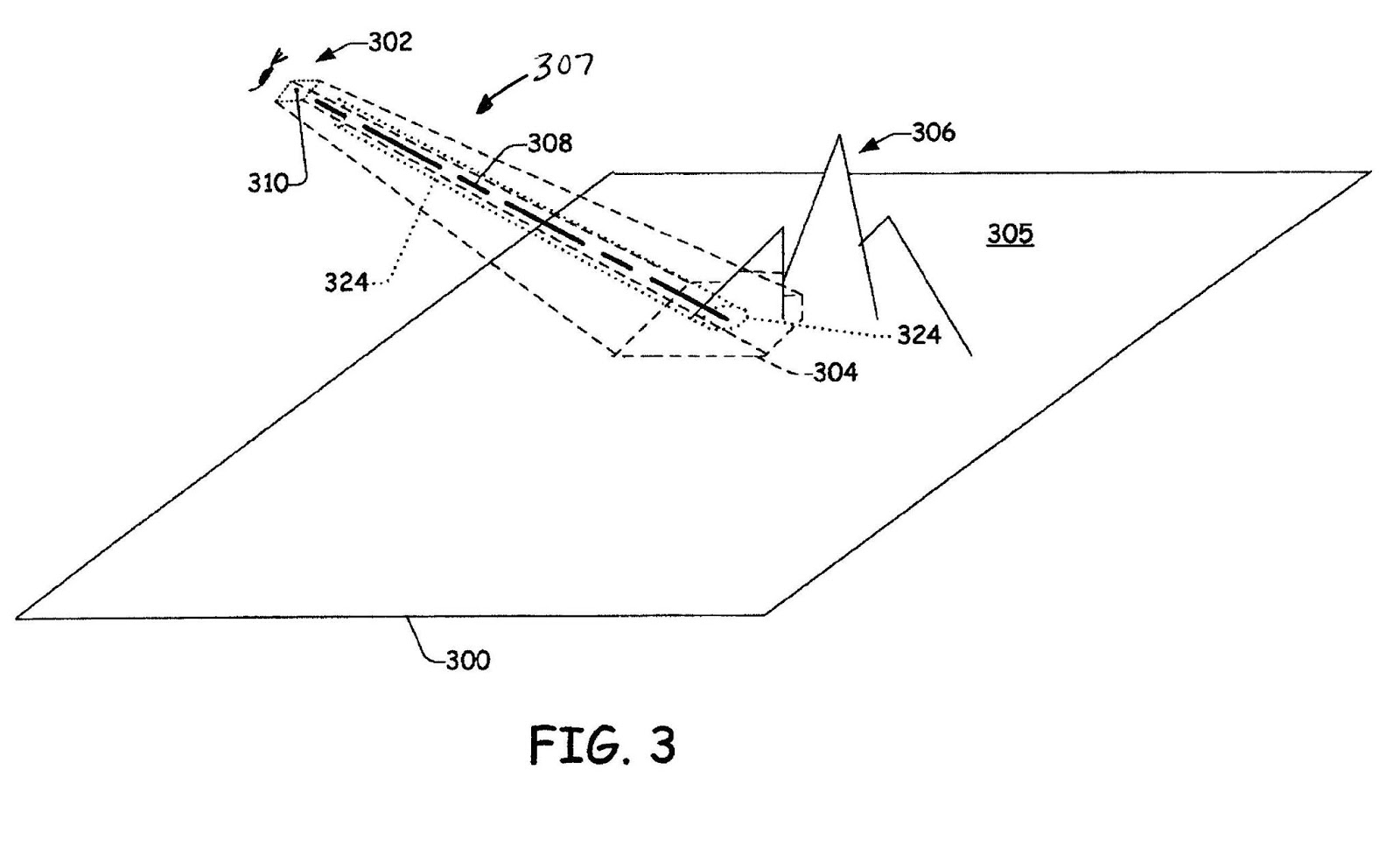
One aspect herein described involves movement of the user's view within the game space. In order to effectively direct units and/or resources, a user can not view the complete game space at all times. Rather, as is commonly done, the user is given a partial view of the game space, typically substantially spaced apart from at least some of the units in the game space, for example from overhead; however, the user has many options regarding this view. Besides selecting which portion of the game space will be viewed, the user is commonly allowed to vary the resolution or the extent of the portion of the game space that is being viewed as well as his/her perspective of the game space, in other words the angle or “tilt” of the view relative to units in the game space. This is illustrated schematically inFIG. 3, where the game space is generally indicated at300and the user's position302relative to the game space300is indicated by an eye. The user's position302can be represented in a three-dimensional coordinate system relative to the game space300. Furthermore, the user's view at that position can be represented by a three-dimensional coordinate system; thus, allowing the perspective of the user's view to be much more complex than just looking straight down upon units in the game space300. In the illustrative example, the game space300includes a terrain305upon which some of the units can be located. InFIG. 3, the user's view from position302in the game space300can be represented as the perimeter of shape304as projected within, for example, upon the terrain305of the game space300. The irregular nature of the perimeter of shape304is provided to represent that the terrain305of game space300can be in three dimensions as well, herein represented by mountains306. At this point it should be noted that view rendered are those objects that are in or partially within a frustum307coinciding with the perimeter of shape304and converging at the user's viewing position302.
This complex manner in which the user's view of the game space300can take is well known in real time strategy games. Furthermore, the specific manner in which the views are generated for the user based on user's position302and view with respect to the game space300are not necessary for understanding aspects herein described since this can be implemented in many different ways depending upon how the user's position302, orientation of view and the positions of units in the game space300are maintained.
With this understanding,FIG. 4depicts in block diagram form one manner in which real time strategy can be implemented. Generally, user400receives through monitor150views generated by a view generation module402that generates views based on the user's position302and orientation of view into the game space300. The user manipulates input buttons136,138, d-pad134and thumbsticks132(1),132(2) of game controller104to provide input into the view generation module402to change his/her view as well as select objects. In the implementation illustrated, a virtual “ray”308(FIG. 3) is determined from the user's position and orientation down into the game space300. The location of the “ray” relative to the rendered view provided to the user on the monitor150is maintained in a fixed position with respect to an edge of the rendered view, for example, in the center of view as rendered on the monitor150. InFIG. 3, this is represented by element310. Generation of the “ray”308is provided by raycast module404. The ray308represents a projection into the game space300, i.e. the point (two-dimensional) or line (three dimensional) of interest of the user in the game space300. More importantly, through use of the “ray”308; the user can identify one or more objects of interest represented at414. The object or objects of interest414, for example, can be one or units, or simply a location in the game space300, which herein can also be considered an “object”.
Information pertaining to object or objects of interest414can be provided to a user action module416. User action module414can receive further input from the user through controller104. In other words, manipulation of the controller104by the user400not only affects the view rendered by the user, but also other actions that can be taken during game play. One common action that can be taken is simply selecting one or more objects from the objects of interest414. Without limitation, some other actions include initiating a menu or taking an action. With respect to initiating a menu, the menu can pertain to the object(s) of interest or selected. For instance, a menu could be brought up providing information of a resource such as a factory. The menu may or may not be adapted to receive further input from the user. With respect to an action, the action could include instructing the object(s) selected to perform an act such as capture or attack another unit, or performing some other form of action on the object(s) of interest.
One particular advantageous aspect of the real time strategy game system described herein is how perceived movement is made in the game space300and how this movement is rendered to the user. As indicated above, the location of the “ray”308relative to the rendered view provided to the user on the monitor is maintained in a fixed position, for example, in the center of view as rendered on the monitor150. With respect to shape304as projected upon the terrain305of the game space300, the ray308coincides with the center of shape304although given the three-dimensional configuration of the terrain305and the user's viewing position302, the position of the ray308may not appear in the center of shape304. Nevertheless, there is a known relationship between a cursor as rendered to the user on the monitor150and the ray308. In one embodiment, the cursor coincides with the ray308, and since the ray308is maintained in a fixed relation with the rendered view, the cursor is maintained in a fixed relation with the rendered view. In a one particular embodiment, the ray308and the cursor are maintained in the center of the rendered view even when the view of the game space300changes. Unlike some real time strategy games that attempt to emulate a pointing device such as a mouse, where movement of the view in the game space300is initiated when the cursor is moved to the edge of the rendered view, in this embodiment, manipulation of the controller104to cause movement in the game space300causes the game space300to appear to move under a stationary cursor. This has been discovered to be an easy manner in which to move around the game space300when using game controller104and where the orientation (i.e. tilt) of the view of the game space300can change in addition to the position of the user's view302in the game space300.
A method500illustrated inFIG. 5summarizes how new viewing positions for the user are obtained. At step502, the user's position relative to at least some units in a game space300is identified. The position is spaced apart from the units and has a parameter indicative of a selected tilt with respect to the units. At step504, a view of a portion of the game space300based on the user's position302is rendered. The view includes the cursor used for selecting one or more units, the cursor being at a known position relative to an edge of the rendered view. At step506, an indication of activation of an input device such as a button or thumbstick132on the game controller104indicating that the user desires a different user's position is received. A new user's position is determined at step508. For at least some if not all of the execution of the game, a new view of a portion of the game space300based on the new user's position is rendered at step510. The new view has maintained the cursor in the known position relative to the edge of the rendered view. This method is repeated for any type of movement such as scrolling and jumping as described further below.
With respect to the user manipulated devices on game controller104, thumbstick132(1) (which is a two-dimensional input device in other words an output therefrom can be considered as having two dimensions) controls the position of the user's viewing position302in approximately a plane, for instance, at a given altitude above the game space300. Thumbstick132(2) (also again another two-dimensional input device) is used to control other aspects of the position or orientation user's viewing position302. In one mode of operation, the thumbstick132(2) controls the manner of tilt of the user's viewing position302with respect to the game space300. Since the virtual ray308extends from the user's viewing position302and the ray308is maintained in a fixed position of the rendered view (e.g. the center), movement of thumbstick132(2) coincides with tilting of the virtual ray308with respect to the game space in two degrees of freedom, (akin to pivoting a rod with one end fixed to a surface). In a second mode of operation, thumbstick132(2) is used to control the altitude of the user's viewing position302by movement of the thumbstick132(2) in a direction indicated by double arrow320, while movement of the thumbstick132(2) in a direction indicated by double arrow322causes either clockwise or counterclockwise rotation of the user's viewing position, or in other words about the virtual ray308. Selection of the desired mode for thumbstick132(2) is controlled the righthand switch138, wherein one of the modes is selected when the switch is activated (depressed by the user) and the other when it is not activated (not depressed by the user).
Constantly during playing of the real time strategy, the user needs to select one or more units to provide instructions to. If it just one unit that the user wants to select, the user moves the user's position throughout the game space300, until the desired unit is under the cursor (also sometimes called a “reticule”), which as stated above can be maintained in a fixed position such as in the center of the monitor150. Once the desired unit coincides with the cursor, the user activates a button such as one of the buttons136.
In a further embodiment, the user can select a group of units using a user defined selection space324in the game space300. The selection space324can be any shape; however, in one embodiment, the selection space324is in the shape of a cylinder or frustum cone that grows radially outward from the ray308with continued activation of a button such as one of the buttons136, which can be the same button referred to above used to select one unit. The size of the selection shape324can be monitored by a shape such as a circle326projected on the terrain. Any unit is a unit that will be deemed selected by the user, if it (or part thereof, if desired) falls within the selection space324. As is known, each unit has a corresponding “bounding box” whereupon a portion such as a corner falls within the selection space324it will be selected. In some instances, different types of units will be selected. If desired, a selection list can be updated to reflect each of the units or types of units. The user can process the selection list, providing instructions to each unit or types of units as desired. Use of a three-dimensional selection space324is advantageous when units can be above the terrain, such as helicopters. If such units are not present a two-dimensional space on the terrain305can be used.
In another manner of selecting units, the user can switch between different types of units that have been identified. For instance, one of the buttons136can be used to switch among different types of units that are currently being displayed to the user. In one manner as illustrated by method600inFIG. 6, this method involves rendering the view having different types of units at step602. At step604, the first time the button is activated, a first type of unit currently being displayed is selected. Then, when the user activates the button again, another type of unit is then selected. This process can continue throughout all the types of units currently being displayed with each activation of the button, where the first type of unit is again selected after cycling through some or all of the available units being displayed. In a further embodiment, if desired, the initial activation of the button could select all of the units regardless of type as indicated at step606. Then, the second activation of the button starts the cycling process of selection of different types of units as described above.
Another particularly advantageous manner in selecting, or at least finding, a unit or a group of units of the same type (groups of which can be user configurable) also allows the user to move quickly within the game space300. This is accomplished for instance by using a designated button on the controller104and repeated actuation of the button. In operation, suppose the user is viewing one portion of the game space300, but then desires to quickly move to any army of soldiers somewhere else in the game space300. Rather than scrolling throughout the game space300, the user activates a designated button on the controller104and the game moves the users viewing window to a window that shows the army of soldiers, for instance, in such a manner so as to coincide with the cursor allowing easy subsequent selection, if desired. If the user has more than one army in the game space300, a subsequent activation of the designated button again moves the users viewing window to a window that shows the second army of soldiers, possibly in such a manner so as to coincide with the cursor allowing easy subsequent selection. Repeated activation of the designated button causes the viewing window and army displayed therein to cycle through some or all of the armies available in the game space300. Different buttons can be used for different units or groups of units of the same type in the same manner as described above with respect to armies.
In yet another embodiment, button(s) can be used to designate other “events” that may be of interest to the user. For instance, a button can be used to allow the user to jump to a battle being fought regardless of the type of units in the battle. Again, repeated activation of the button will allow the user to cycle through some or all of the events of interest. It should be noted an event of interest need not be all of the same type such as current battles being fought. Rather, the events of interest may change dynamically during play of the game. For instance, the system may inform the user that a new fight has just started, whereupon activation of the button, takes the user to the location of the new fight. As another example, the system may then inform the user that a new tank is now available, in which case activation of the button will take the user to the location of the new tank.
One particularly advantageous button assembly to use is the d-pad button assembly134. As is commonly known, the d-pad button assembly134is a rocker button assembly having a suitably shaped button such as disc that can be slightly tilted in effect activating or appearing to activate different switches in fixed positions such as the “12-O'clock, 3-O'clock, 6-O'clock and 9-O'clock” positions. By also merely pushing the d-pad button assembly straight down, another different switch activation is realized. Each of the different activations of the d-pad134can be used to designate a different type of unit or event of interest. Besides those described above, one of the buttons can be used to jump to a view of a base as illustrated at step506. The designations of the buttons such as the various positions of the d-pad can be preselected, but if desired a suitable interface can allow the user to change the designations as desired.
In addition to moving around in the game space300and selecting units, the user may occasionally need to bring up a menu and make some selections within the menu. In real time strategy games, this has been difficult, particularly when prior games have tried to have the controller104emulate a pointing device such as a mouse. Referring toFIG. 8, a menu system for a real time strategy game with operation by a game controller is provided. Referring also toFIG. 7, the user interface menu system is characterized by displaying a menu700(step702) and “locking” the cursor within the menu700until an exit button or option is selected (step708). Within the menu700, the user can choose among different options by moving around the menu700(step704) using a designated button on the controller104and make selections (step706), for example, using another button on the controller104.FIG. 8illustrates the exemplary menu700that includes four options related to a factory of a real time strategy game. Other aspects of the game would have other menus. By way of example, when the factory is selected, menu700is displayed. Once displayed, one of the options such as “build a tank” can be highlighted. If the user would like a tank built, the user can activate a designated button on the controller104, where multiple activations will cause multiple tanks to be built. As desired, the user can move throughout the menu700in order to perform other actions such as “build a helicopter”, “build a truck”, etc. Once all desired actions have been selected, the user can activate a designated button on the controller104and/or select a designated option on the menu700such as “Exit” to exit from the menu700. Organization of the menu options in the form of a circle or circular shape, where movement within the menu (i.e. options are identified) is in circular order either clockwise and/or counterclockwise is particularly easy for the user to understand, and thus, predict how many operations of the button are necessary to obtain the desired option.
Displaying and interfacing with menus in a manner described above is easy to understand, and more importantly, is easy to perform, because in real time strategy games the user must be able to access, manipulate and exit menus quickly with the game controller104.
Although the subject matter has been described in language specific to structural features and/or methodological acts, it is to be understood that the subject matter defined in the appended claims is not necessarily limited to the specific features or acts described above as has been determined by the courts. Rather, the specific features and acts described above are disclosed as example forms of implementing the claims.
Claims
- A system comprising: a processor;an input device;a rendering device;and a computer readable storage medium having instructions accessible by the processor and which when executed on the processor conduct a real time strategy game based on user input from the input device, the instructions comprising: operating a plurality of units in a game space, wherein operating includes selectively providing instructions to each of the plurality of units in the game space, each of the units having a unit type and taking action in the game space based on each corresponding instruction;identifying a user's position in the game space, the position being spaced apart from the units and having a parameter indicative of a first tilt with respect to the units;rendering a first view of a portion of the game space on the rendering device based on the user's position, the first view having the first tilt and including a cursor used for selecting one or more units;selecting a set of the units to which a corresponding instruction will be provided in the first view;reporting to the user that an event has occurred, the event comprising a first that has occurred in the game;receiving an indication of activation of the input device indicating that the user desires a different user's position;determining a new user's position, with the processor, that is spaced apart from the units and has a parameter indicative of a second tilt with respect to the units that is different than the first tilt, wherein the new user's position corresponds to the event that has occurred in the game;and for at least some of the execution of the game, rendering a new view of a portion of the game space based on the new user's position, the new view having the second tilt.
- The system of claim 1 wherein receiving the indication, determining the new user's position and rendering the new view is repeated sequentially so as to appear that the game space is scrolling by from the first tilt to the second tilt, and wherein with each new view the cursor is maintained in a same known position relative to the edge of the rendered view.
- The system of claim 1 , wherein the input device comprises a user activated button, and wherein the plurality of units comprise a plurality of different unit types and successive activation of the user activated button selects a different set of the units based on the unit types, wherein the set of units comprise units of a first unit type, and the different set of units comprise units of a second, different unit type.
- The system of claim 2 wherein the new user's position comprises a position of the game space spaced apart sufficiently from the game space of the first view such that rendering of one of said each new view does not contain any portion of the game space from the first view.
- The system of claim 1 , wherein receiving an indication of activation of the input device indicating that the user desires a different user's position comprises: receiving an indication that the user desires to be taken to a location of the event, wherein the new user's position is determined based on the location of the event.
- The system of claim 1 wherein receiving the indication, determining the new user's position and rendering the new view is repeated sequentially so as to render different events of the same type.
- The system of claim 1 wherein the new user's position corresponds to a selected type of unit in the game space.
- The system of claim 7 wherein receiving the indication, determining the new user's position and rendering the new view is repeated sequentially so as to render different units of the same type.
- The system of claim 8 wherein the input device comprises a button, and the instructions further comprise receiving an indication of activation of the button indicating that the user desires a different user's position;and wherein determining the new user's position is based on activation of the button;and wherein receiving the indication, determining the new user's position and rendering the new view is repeated sequentially so as to render different events of the same type.
- The system of claim 9 wherein the input device comprises a second button and the instructions further comprise receiving an indication of activation of the second button indicating that the user desires a different user's position;wherein determining the new user's position is based on activation of the second button;and wherein the new user's position corresponds to a view of a base.
- The system of claim 10 wherein the input device comprises a d-pad button assembly, the d-pad button assembly being used for the button and the second button.
- The system of claim 1 wherein the input device comprises a two-dimensional input device operable by the user configured to indicate a new user's position comprising a change in tilt, the system having a second input device comprising a two-dimensional input device operable by the user configured to indicate a new user's position comprising a change in position other than a change in tilt.
- A computer-implemented method of conducting a real time strategy game based on user input from an input device, the method comprising: operating a plurality of units in a game space using a computer processor, wherein the game space comprises a terrain, wherein operating includes selectively providing instructions to each of the plurality of units in the game space, each of the units taking action in the game space based on each corresponding instruction;rendering a view of a portion of a game space, the view simultaneously showing a terrain and a set of the units that comprises some but not all of the plurality of units, wherein the set of units comprises a first unit of a first type that is visually shown on the terrain and a second unit of a second type that is visually shown over the terrain;and while the view is rendered with said first unit being of the first type visually shown on the terrain and second unit of the second type visually shown over the terrain, receiving activation of the input device and, in response, sequentially visually identifying units in the view based on whether the units are of the first type or the second type.
- The method of claim 13 and further comprising identifying all of the units in the view with activation of the input device.
- The method of claim 13 wherein the input device comprises a two-dimensional input device operable by the user configured to indicate a new user's position comprising a change in tilt, the system having a second input device comprising a two-dimensional input device operable by the user configured to indicate a new user's position comprising a change in position other than a change in tilt.
- The method of claim 13 , further comprising selecting a first plurality units in a view using a cursor based on a positional relationship of the first plurality of units to the cursor in the view, wherein the cursor maintains a same position with respect to an edge of the view being rendered for each view that is rendered.
- The method of claim 16 wherein the positional relationship of the first plurality of units to the cursor defines a three dimensional shape in the game space.
- A system comprising: a processor;an input device having a user activated button;a rendering device;and a computer readable storage medium having instructions accessible by the processor and which when executed on the processor conduct a real time strategy game based on user input from the input device, the instructions comprising: operating a plurality of units of a plurality of different unit types in a game space, each of the units taking action in the game space based on corresponding instructions;determining a first user position relative to at least some units in the game space, the first user position being spaced apart from the units and having a parameter indicative of a first tilt with respect to the units;rendering a first view of a portion of the game space on the rendering device based on the first user position, the first view not corresponding to a view as seen by any of the units in the game space, the first view having the first tilt and including a cursor for selecting a unit, the cursor being at a known position relative to an edge of the rendered first view;receiving an indication of activation of the input device and, in response, identifying a set of the units based on the unit types;determining a second user position, with the processor, based on the identified set of the units, the second user position being spaced apart from the units and having a parameter indicative of a second tilt with respect to the units that is different than the first tilt;and for at least some of the execution of the game, rendering a second view of a portion of the game space based on the second user position, the second view having the second tilt and showing the identified set of units, while maintaining the cursor in the known position relative to the edge of the rendered view, the second view not corresponding to a view as seen by any of the units in the game space.
- The system of claim 18 , wherein rendering the second view comprises: switching from rendering the first view to rendering the second view while maintaining the cursor at the same position relative to the edge of the rendered view, such that the cursor remains substantially stationary on the rendering device.
- The system of claim 19 , wherein both the first view and the second view are third person views of the game space.
Disclaimer: Data collected from the USPTO and may be malformed, incomplete, and/or otherwise inaccurate.