U.S. Pat. No. 8,882,592
GAME SYSTEM, GAME APPARATUS, COMPUTER-READABLE STORAGE MEDIUM HAVING STORED THEREIN GAME PROGRAM, AND GAME PROCESSING METHOD
AssigneeNintendo Co., Ltd.
Issue DateOctober 25, 2011
Illustrative Figure
Abstract
An example game apparatus calculates the attitude of a terminal device on the basis of a value of a gyro sensor of the terminal device. The game apparatus sets the position of an aim in a game image on the basis of the calculated attitude of the terminal device, and also sets the attitude of a virtual camera. The game apparatus sets the firing direction of an arrow on the basis of the position of the aim, and causes the arrow to be fired in the firing direction in accordance with the cessation of a touch operation on a touch panel of the terminal device.
Description
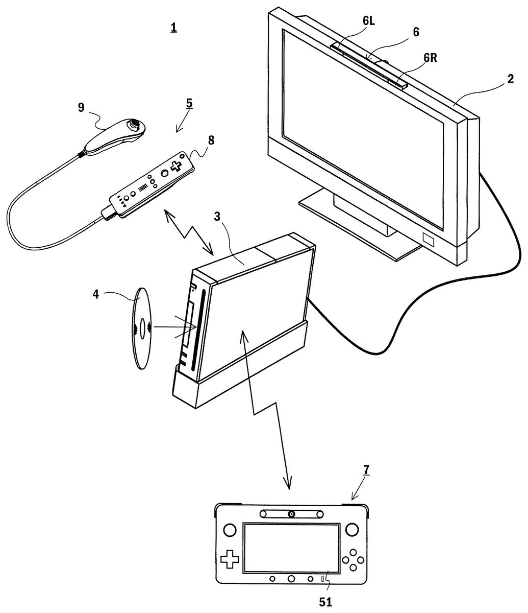
DETAILED DESCRIPTION OF NON-LIMITING EXAMPLE EMBODIMENTS [1. Overall Configuration of Game System] With reference to the drawings, a description is given of a game system1according to an exemplary embodiment.FIG. 1is an external view showing a non-limiting example of the game system1. Referring toFIG. 1, the game system1includes a stationary display device (hereinafter referred to as a “television”)2typified by, for example, a television receiver, a stationary game apparatus3, an optical disk4, a controller5, a marker device6, and a terminal device7. In the game system1, the game apparatus3performs game processing on the basis of a game operation performed using the controller5, and a game image obtained by the game processing is displayed on the television2and/or the terminal device7. The optical disk4is detachably inserted into the game apparatus3, the optical disk4being an example of an information storage medium exchangeably used for the game apparatus3. The optical disk4has stored therein an information processing program (typically, a game program) to be executed by the game apparatus3. On the front surface of the game apparatus3, an insertion opening for the optical disk4is provided. The game apparatus3reads and executes the information processing program stored in the optical disk4inserted in the insertion opening, and thereby performs the game processing. The game apparatus3is connected to the television2via a connection cord. The television2displays the game image obtained by the game processing performed by the game apparatus3. The television2has a loudspeaker2a(FIG. 2). The loudspeaker2aoutputs a game sound obtained as a result of the game processing. It should be noted that in another embodiment, the game apparatus3and the stationary display device may be integrated together. Further, the communication between the game apparatus3and the television2may be wireless communication. In the periphery of the screen of the television2(above the screen inFIG. 1), the marker device6is installed. Although described in detail later, a user (player) ...
DETAILED DESCRIPTION OF NON-LIMITING EXAMPLE EMBODIMENTS
[1. Overall Configuration of Game System]
With reference to the drawings, a description is given of a game system1according to an exemplary embodiment.FIG. 1is an external view showing a non-limiting example of the game system1. Referring toFIG. 1, the game system1includes a stationary display device (hereinafter referred to as a “television”)2typified by, for example, a television receiver, a stationary game apparatus3, an optical disk4, a controller5, a marker device6, and a terminal device7. In the game system1, the game apparatus3performs game processing on the basis of a game operation performed using the controller5, and a game image obtained by the game processing is displayed on the television2and/or the terminal device7.
The optical disk4is detachably inserted into the game apparatus3, the optical disk4being an example of an information storage medium exchangeably used for the game apparatus3. The optical disk4has stored therein an information processing program (typically, a game program) to be executed by the game apparatus3. On the front surface of the game apparatus3, an insertion opening for the optical disk4is provided. The game apparatus3reads and executes the information processing program stored in the optical disk4inserted in the insertion opening, and thereby performs the game processing.
The game apparatus3is connected to the television2via a connection cord. The television2displays the game image obtained by the game processing performed by the game apparatus3. The television2has a loudspeaker2a(FIG. 2). The loudspeaker2aoutputs a game sound obtained as a result of the game processing. It should be noted that in another embodiment, the game apparatus3and the stationary display device may be integrated together. Further, the communication between the game apparatus3and the television2may be wireless communication.
In the periphery of the screen of the television2(above the screen inFIG. 1), the marker device6is installed. Although described in detail later, a user (player) can perform a game operation of moving the controller5. The marker device6is used by the game apparatus3to calculate the motion, the position, the attitude, and the like of the controller5. The marker device6includes two markers6R and6L at its two ends. The marker6R (the same applies to the marker6L) is composed of one or more infrared LEDs (Light Emitting Diodes), and outputs infrared light forward from the television2. The marker device6is connected to the game apparatus3in a wireless (or wired) manner. This enables the game apparatus3to control each of the infrared LEDs included in the marker device6to be lit on or off. It should be noted that the marker device6is portable, which allows the user to install the marker device6at a given position.FIG. 1shows the form where the marker device6is installed on the television2. The installation position and the facing direction of the marker device6, however, are a given position and a given direction.
The controller5provides the game apparatus3with operation data based on the operation performed on the controller5itself. In the present embodiment, the controller5has a main controller8and a sub-controller9, and the sub-controller9is detachably attached to the main controller8. The controller5and the game apparatus3are capable of communicating with each other by wireless communication. In the present embodiment, the wireless communication between the controller5and the game apparatus3uses, for example, the Bluetooth (registered trademark) technology. It should be noted that in another embodiment, the controller5and the game apparatus3may be connected together in a wired manner. Further, inFIG. 1, the game system1includes one controller5; however, the game system1may include a plurality of controllers5. That is, the game apparatus3is capable of communicating with a plurality of controllers, and therefore, the simultaneous use of a predetermined number of controllers allows a plurality of people to play a game. A detailed configuration of the controller5will be described later.
The terminal device7is small enough to be held by a user. This allows the user to use the terminal device7by moving the terminal device7while holding it, or placing the terminal device7at a given position. Although a detailed configuration will be described later, the terminal device7includes an LCD (Liquid Crystal Display)51, which serves as display means, and input means (a touch panel52, a gyro sensor64, and the like described later). The terminal device7and the game apparatus3are capable of communicating with each other in a wireless (or wired) manner. The terminal device7receives, from the game apparatus3, data of an image (e.g., a game image) generated by the game apparatus3, and displays the image on the LCD51. It should be noted that in the present embodiment, an LCD is employed as a display device. Alternatively, the terminal device7may have another given display device such as a display device using EL (electroluminescence), for example. Further, the terminal device7transmits, to the game apparatus3, operation data based on the operation performed on the terminal device7itself.
[2. Internal Configuration of Game Apparatus3]
Next, with reference toFIG. 2, the internal configuration of the game apparatus3is described.FIG. 2is a block diagram showing the internal configuration of a non-limiting example of the game apparatus3. The game apparatus3includes a CPU (Central Processing Unit)10, a system LSI11, an external main memory12, a ROM/RTC13, a disk drive14, an AV-IC15, and the like.
The CPU10performs the game processing by executing the game program stored in the optical disk4, and functions as a game processor. The CPU10is connected to the system LSI11. The system LSI11is connected to, as well as the CPU10, the external main memory12, the ROM/RTC13, the disk drive14, and the AV-IC15. The system LSI11, for example, controls data transfer between the components connected thereto, generates images to be displayed, and obtains data from external devices. It should be noted that the internal configuration of the system LSI11will be described later. The volatile-type external main memory12stores a program, such as the game program read from the optical disk4or the game program read from a flash memory17, and various other data. The external main memory12is used as a work area or a buffer area of the CPU10. The ROM/RTC13has a ROM (a so-called boot ROM) having incorporated therein a program for starting up the game apparatus3, and also has a clock circuit (RTC: Real Time Clock) for counting time. The disk drive14reads program data, texture data, and the like from the optical disk4, and writes the read data into an internal main memory11edescribed later or the external main memory12.
The system LSI11includes an input/output processor (I/O processor)11a, a GPU (Graphics Processor Unit)11b, a DSP (Digital Signal Processor)11c, a VRAM (Video RAM)11d, and an internal main memory11e. Although not shown in the figures, the components11athrough11eare connected together via an internal bus.
The GPU11bforms a part of drawing means, and generates an image in accordance with a graphics command (a command to draw an image) from the CPU10. The VRAM11dstores data (such as polygon data and texture data) that is necessary for the GPU11bto execute the graphics command. When the image is generated, the GPU11buses the data stored in the VRAM11dto generate image data. It should be noted that in the present embodiment, the game apparatus3generates both a game image to be displayed on the television2and a game image to be displayed on the terminal device7. Hereinafter, occasionally, the game image to be displayed on the television2is referred to as a “television game image”, and the game image to be displayed on the terminal device7is referred to as a “terminal game image”.
The DSP11cfunctions as an audio processor, and generates audio data using sound data and acoustic waveform (timbre) data that are stored in the internal main memory11eor the external main memory12. It should be noted that in the present embodiment, a game sound is generated in a similar manner to a game image, that is, both a game sound to be output from the loudspeaker of the television2and a game sound to be output from the loudspeakers of the terminal device7are generated. Hereinafter, occasionally, the game sound to be output from the television2is referred to as a “television game sound”, and the game sound to be output from the terminal device7is referred to as a “terminal game sound”.
Data of, among images and sounds generated by the game apparatus3as described above, an image and a sound to be output from the television2is read by the AV-IC15. The AV-IC15outputs the read data of the image to the television2through an AV connector16, and also outputs the read data of the sound to the loudspeaker2abuilt into the television2. This causes the image to be displayed on the television2, and also causes the sound to be output from the loudspeaker2a.
In addition, data of, among images and sounds generated by the game apparatus3, an image and a sound to be output from the terminal device7is transmitted to the terminal device7by the input/output processor11aor the like. The transmission of the data to the terminal device7by the input/output processor11aor the like will be described later.
The input/output processor11atransmits and receives data to and from the components connected thereto, or downloads data from external devices. The input/output processor11ais connected to the flash memory17, a network communication module18, a controller communication module19, an extension connector20, a memory card connector21, and a codec LSI27. The network communication module18is connected to an antenna22. The controller communication module19is connected to an antenna23. The codec LSI27is connected to a terminal communication module28. The terminal communication module28is connected to an antenna29.
The game apparatus3is connected to a network such as the Internet, and is thereby capable of communicating with external information processing apparatuses (e.g., other game apparatuses, various servers, and various information processing apparatuses). That is, the input/output processor11ais connected to a network such as the Internet via the network communication module18and the antenna22, and is thereby capable of communicating with external information processing apparatuses also connected to the network. The input/output processor11aperiodically accesses the flash memory17, and detects the presence or absence of data that needs to be transmitted to the network. When such data is present, the input/output processor11atransmits the data to the network through the network communication module18and the antenna22. The input/output processor11aalso receives data transmitted from an external information processing apparatus or data downloaded from a download server, through the network, the antenna22, and the network communication module18, and stores the received data in the flash memory17. The CPU10executes the game program to thereby read the data stored in the flash memory17and use the read data for the game program. The flash memory17may have stored therein data (data stored after or during the game) saved as a result of playing the game using the game apparatus3, as well as data to be transmitted to, or data received from, an external information processing apparatus. Further, the flash memory17may have stored therein the game program.
In addition, the game apparatus3can receive operation data from the controller5. That is, the input/output processor11areceives operation data transmitted from the controller5through the antenna23and the controller communication module19, and stores (temporarily stores) the operation data in a buffer area of the internal main memory11eor the external main memory12.
In addition, the game apparatus3can transmit and receive data of an image, a sound, and the like to and from the terminal device7. When transmitting a game image (terminal game image) to the terminal device7, the input/output processor11aoutputs data of the game image generated by the GPU11bto the codec LSI27. The codec LSI27performs a predetermined compression process on the image data from the input/output processor11a. The terminal communication module28wirelessly communicates with the terminal device7. Accordingly, the image data compressed by the codec LSI27is transmitted from the terminal communication module28to the terminal device7through the antenna29. It should be noted that in the present embodiment, the image data transmitted from the game apparatus3to the terminal device7is used in the game. Therefore, in the game, a delay in the display of the image adversely affects the operability of the game. Thus, it is preferable that a delay in the transmission of the image data from the game apparatus3to the terminal device7should be prevented as far as possible. Accordingly, in the present embodiment, the codec LSI27compresses the image data using a highly efficient compression technique such as the H.264 standard. It should be noted that another compression technique may be used, or the image data may be transmitted without being compressed if the communication speed is fast enough. Further, the terminal communication module28may be, for example, a Wi-Fi-certified communication module and may wirelessly communicate with the terminal device7at a high speed, using, for example, MIMO (Multiple Input Multiple Output) technology employed based on the IEEE 802.11n standard, or may use another communication method.
In addition, the game apparatus3transmits, as well as the image data, audio data to the terminal device7. That is, the input/output processor11aoutputs audio data generated by the DSP11cto the terminal communication module28through the codec LSI27. The codec LSI27performs a compression process on the audio data in a similar manner to that performed on the image data. Any method of compression may be performed on the audio data. It is, however, preferable that the method should have a high compression ratio, and should not cause a significant deterioration of the sound. In another embodiment, the audio data may be transmitted without being compressed. The terminal communication module28transmits the compressed image data and audio data to the terminal device7through the antenna29.
In addition, the game apparatus3transmits, as well as the image data and the audio data described above, various control data to the terminal device7where necessary. The control data is data representing a control instruction to be given to a component included in the terminal device7. The control data represents, for example, an instruction to control a marker section (a marker section55shown inFIG. 11), and an instruction to control a camera (a camera56shown inFIG. 11) to capture an image. The input/output processor11atransmits the control data to the terminal device7in accordance with an instruction from the CPU10. It should be noted that in the present embodiment, the codec LSI27does not perform a compression process on the control data. Alternatively, in another embodiment, the codec LSI27may perform a compression process on the control data. It should be noted that the above data transmitted from the game apparatus3to the terminal device7may be encrypted where necessary, or may not be encrypted.
In addition, the game apparatus3can receive various data from the terminal device7. Although described in detail later, in the present embodiment, the terminal device7transmits operation data, image data, and audio data. The data transmitted from the terminal device7is received by the terminal communication module28through the antenna29. Here, the image data and the audio data from the terminal device7are subjected to compression processes similarly to those performed on the image data and the audio data, respectively, from the game apparatus3to the terminal device7. Accordingly, the image data and the audio data are transmitted from the terminal communication module28to the codec LSI27, are subjected to decompression processes by the codec LSI27, and are output to the input/output processor11a. On the other hand, the operation data from the terminal device7may not be subjected to a compression process because the operation data is smaller in amount than the image data and the audio data. Further, the operation data may be encrypted where necessary, or may not be encrypted. Thus, the operation data is received by the terminal communication module28, and is subsequently output to the input/output processor11athrough the codec LSI27. The input/output processor11astores (temporarily stores) the data received from the terminal device7in a buffer area of the internal main memory11eor the external main memory12.
In addition, the game apparatus3can be connected to another device and an external storage medium. That is, the input/output processor11ais connected to the extension connector20and the memory card connector21. The extension connector20is a connector for an interface such as USB or SCSI. The extension connector20can be connected to a medium such as an external storage medium, or can be connected to a peripheral device such as another controller, or can be connected to a wired communication connector and thereby communicate with a network instead of the network communication module18. The memory card connector21is a connector for connecting an external storage medium such as a memory card. For example, the input/output processor11acan access an external storage medium through the extension connector20or the memory card connector21, and thereby can store data in, or read data from, the external storage medium.
The game apparatus3includes a power button24, a reset button25, and an eject button26. The power button24and the reset button25are connected to the system LSI11. When the power button24has been turned on, power is supplied to each component of the game apparatus3from an external power supply through an AC adaptor not shown in the figures. When the reset button25has been pressed, the system LSI11restarts a start-up program for the game apparatus3. The eject button26is connected to the disk drive14. When the eject button26has been pressed, the optical disk4is ejected from the disk drive14.
It should be noted that in another embodiment, some components among all the components of the game apparatus3may be configured as an extension device different from the game apparatus3. In this case, the extension device may be connected to the game apparatus3via, for example, the extension connector20described above. Specifically, the extension device may include components such as the codec LSI27, the terminal communication module28, and the antenna29, and may be attachable to and detachable from the extension connector20. This enables the game apparatus to communicate with the terminal device7by connecting the extension device to a game apparatus that does not include all the components described above.
[3. Configuration of Controller5]
Next, with reference toFIGS. 3 through 7, the controller5is described. As described above, the controller5includes the main controller8and the sub-controller9.FIG. 3is a perspective view showing the external configuration of a non-limiting example of the main controller8.FIG. 4is a perspective view showing the external configuration of a non-limiting example of the main controller8.FIG. 3is a perspective view of a non-limiting example of the main controller8from the top rear thereof.FIG. 4is a perspective view of a non-limiting example of the main controller8from the bottom front thereof.
Referring toFIGS. 3 and 4, the main controller8includes a housing31formed by, for example, plastic molding. The housing31has a generally parallelepiped shape extending in its longitudinal direction from front to rear (the Z1-axis direction shown inFIG. 3). The entire housing31can be held with one hand by an adult or even a child. A user can perform a game operation by pressing buttons provided on the main controller8, and moving the main controller8per se to change the position and the attitude (tilt) thereof.
The housing31includes a plurality of operation buttons. As shown inFIG. 3, on the top surface of the housing31, the following are provided: a cross button32a; a 1-button32b; a 2-button32c; an A-button32d; a minus button32e; a home button32f; a plus button32g; and a power button32h. In the present specification, the top surface of the housing31, on which the buttons32athrough32hare provided, is occasionally referred to as a “button surface”. On the other hand, as shown inFIG. 4, on the bottom surface of the housing31, a recessed portion is formed. On the slope surface of the recessed portion on the rear surface side, a B-button32iis provided. The operation buttons (switches)32athrough32iare each appropriately assigned a function in accordance with the information processing program to be executed by the game apparatus3. Further, the power switch32his used to remotely turn on/off the power to the game apparatus3. The top surfaces of the home button32fand the power button32hare buried in the top surface of the housing31. This makes it possible to prevent the user from inadvertently pressing the home button32for the power button32h.
On the rear surface of the housing31, a connector33is provided. The connector33is used to connect the main controller8to another device (e.g., the sub-controller9or another sensor unit). Further, on the rear surface of the housing31, latch holes33aare provided to the respective sides of the connector33in order to prevent said another device from easily separating from the housing31.
In the posterior of the top surface of the housing31, a plurality of (four inFIG. 3) LEDs34athrough34dare provided. Here, the controller5(the main controller8) is appropriately assigned a controller type (number) in order to distinguish the controller5from other controllers5. The LEDs34athrough34dare used to, for example, notify the user of the controller type currently set for the controller5that they are using, or to notify the user of the remaining battery charge. Specifically, when a game operation is performed using the controller5, one of the plurality of LEDs34athrough34dis lit on in accordance with the corresponding controller type.
In addition, the controller5includes an imaging information calculation section35(FIG. 6). As shown inFIG. 4, on the front surface of the housing31, a light incident surface35aof the imaging information calculation section35is provided. The light incident surface35ais formed of a material that allows the infrared light from the markers6R and6L to at least pass therethrough.
Between the first button32band the home button32fon the top surface of the housing31, sound holes31aare formed so as to emit a sound from a loudspeaker47(FIG. 5) built into the main controller8to the outside.
Next, with reference toFIGS. 5 and 6, the internal structure of the main controller8is described.FIGS. 5 and 6are diagrams showing the internal structure of a non-limiting example of the main controller8. It should be noted thatFIG. 5is a perspective view showing the state where an upper casing (a part of the housing31) of the main controller8is removed.FIG. 6is a perspective view showing the state where a lower casing (a part of the housing31) of the main controller8is removed.FIG. 6is a perspective view showing the reverse side of a substrate30shown inFIG. 5.
Referring toFIG. 5, a substrate30is fixed within the housing31. On the top main surface of the substrate30, the following are provided: the operation buttons32athrough32h; the LEDs34athrough34d; an acceleration sensor37; an antenna45; a loudspeaker47; and the like. These components are connected to a microcomputer42(seeFIG. 6) via wiring (not shown) formed on the substrate30and the like. In the present embodiment, the acceleration sensor37is located off the center of the main controller8along an X1-axis direction. This facilitates the calculation of the motion of the main controller8when the main controller8is rotated about a Z1-axis. Further, the acceleration sensor37is also located anterior to the center of the main controller8along its longitudinal direction (the Z1-axis direction). A wireless module44(FIG. 6) and the antenna45allow the controller5(the main controller8) to function as a wireless controller.
On the other hand, referring toFIG. 6, at the front edge of the bottom main surface of the substrate30, the imaging information calculation section35is provided. The imaging information calculation section35includes an infrared filter38, a lens39, an image pickup device40, and an image processing circuit41that are placed in order starting from the anterior of the controller5. The members38through41are each attached to the bottom main surface of the substrate30.
In addition, on the bottom main surface of the substrate30, a vibrator46is attached. The vibrator46is, for example, a vibration motor or a solenoid, and is connected to the microcomputer42via wiring formed on the substrate30and the like. The main controller8is vibrated by the actuation of the vibrator46on the basis of an instruction from the microcomputer42. This makes it possible to achieve a so-called vibration-feedback game where the vibration is conveyed to the player's hand holding the main controller8. In the present embodiment, the vibrator46is located slightly anterior to the center of the housing31. The location of the vibrator46closer to the front end than the center of the main controller8makes it possible to vibrate the entire main controller8significantly by the vibration of the vibrator46. Further, the connector33is attached to the rear edge of the main bottom surface of the substrate30. It should be noted that the main controller8includes, as well as the components shown inFIGS. 5 and 6, a quartz oscillator that generates a reference clock of the microcomputer42, an amplifier that outputs an audio signal to the loudspeaker47, and the like.
FIG. 7is a perspective view showing the external configuration of a non-limiting example of the sub-controller9. The sub-controller9includes a housing80formed by, for example, plastic molding. The entire housing80can be held with one hand by an adult or even a child. Also the use of the sub-controller9allows a player to perform a game operation by operating buttons and a stick, and changing the position and the facing direction of the controller per se.
As shown inFIG. 7, on the front end side (a Z2-axis positive side) of the top surface (the surface on a Y2-axis negative direction side) of the housing80, an analog joystick81is provided. Further, although not shown in the figures, at the front end of the housing80, a front end surface slightly inclined backward is provided. On the front end surface, a C-button and a Z-button are provided so as to be arranged in the up-down direction (the Y2-axis direction shown inFIG. 7). The analog joystick81and the buttons (the C-button and the Z-button) are each appropriately assigned a function in accordance with the game program to be executed by the game apparatus3. It should be noted that the analog joystick81and the buttons are occasionally collectively referred to as an “operation section82” (seeFIG. 8).
In addition, although not shown inFIG. 7, the sub-controller9has an acceleration sensor (an acceleration sensor83shown inFIG. 8) within the housing80. In the present embodiment, the acceleration sensor83is one similar to the acceleration sensor37of the main controller8. The acceleration sensor83may be, however, one different from the acceleration sensor37, and may be one that detects the acceleration in one predetermined axis, or the accelerations in two predetermined axes.
In addition, as shown inFIG. 7, one end of a cable is connected to the rear end of the housing80. Although not shown inFIG. 7, a connector (a connector84shown inFIG. 8) is connected to the other end of the cable. The connector can be connected to the connector33of the main controller8. That is, the connection between the connector33and the connector84causes the main controller8and the sub-controller9to be connected together.
It should be noted that inFIG. 3 through 7, the shapes of the main controller8and the sub-controller9, the shapes of the operation buttons, the numbers and the installation positions of the acceleration sensor and the vibrator, and the like are merely illustrative, and may be other shapes, numbers, and installation positions. In the present embodiment, the capturing direction of capturing means of the main controller8is the Z1-axis positive direction, but the capturing direction may be any direction. That is, the position of the imaging information calculation section35(the light incident surface35aof the imaging information calculation section35) of the controller5is not necessarily on the front surface of the housing31, and may be on another surface so long as light can be obtained from outside the housing31.
FIG. 8is a block diagram showing the configuration of a non-limiting example of the controller5. As shown inFIG. 8, the main controller8includes an operation section32(the operation buttons32athrough32i), the imaging information calculation section35, a communication section36, the acceleration sensor37, and a gyro sensor48. Further, the sub-controller9includes the operation section82and the acceleration sensor83. The controller5transmits data representing the particulars of the operation performed on the controller5itself, to the game apparatus3as operation data. It should be noted that, hereinafter, occasionally, the operation data to be transmitted from the controller5is referred to as “controller operation data”, and the operation data to be transmitted from the terminal device7is referred to as “terminal operation data”.
The operation section32includes the operation buttons32athrough32idescribed above, and outputs data representing the input state of each of the operation buttons32athrough32i(whether or not each of the operation buttons32athrough32ihas been pressed), to the microcomputer42of the communication section36.
The imaging information calculation section35is a system for analyzing image data of an image captured by the capturing means, determining an area having a high brightness in the image data, and calculating the center of gravity, the size, and the like of the area. The imaging information calculation section35has, for example, a maximum sampling period of about 200 frames/seconds, and therefore can trace and analyze even a relatively fast motion of the controller5.
The imaging information calculation section35includes the infrared filter38, the lens39, the image pickup element40, and the image processing circuit41. The infrared filter38allows only infrared light, among the light incident on the front surface of the controller5, to pass therethrough. The lens39collects the infrared light having passed through the infrared filter38, and makes the infrared light incident on the image pickup element40. The image pickup element40is a solid-state image pickup element such as a CMOS sensor or a CCD sensor. The image pickup element40receives the infrared light collected by the lens39, and outputs an image signal. Here, capturing targets, namely the marker section55of the terminal device7and the marker device6, each include markers that output infrared light. The provision of the infrared filter38allows the image pickup element40to receive only the infrared light having passed through the infrared filter38, and generate image data. This makes it possible to accurately capture the capturing targets (the marker section55and/or the marker device6). Hereinafter, an image captured by the image pickup element40is referred to as a “captured image”. The image data generated by the image pickup element40is processed by the image processing circuit41. The image processing circuit41calculates the positions of the capturing targets in the captured image. The image processing circuit41outputs coordinates representing the calculated positions to the microcomputer42of the communication section36. Data of the coordinates is transmitted from the microcomputer42to the game apparatus3as operation data. Hereinafter, the coordinates described above are referred to as “marker coordinates”. The marker coordinates change in accordance with the facing direction (tilt angle) and the position of the controller5per se. This enables the game apparatus3to calculate the facing direction and the position of the controller5using the marker coordinates.
It should be noted that in another embodiment, the controller5may not include the image processing circuit41, and the captured image per se may be transmitted from the controller5to the game apparatus3. In this case, the game apparatus3may have a circuit or a program that has functions similar to those of the image processing circuit41, and may calculate the marker coordinates described above.
The acceleration sensor37detects the acceleration (including the gravitational acceleration) of the controller5. That is, the acceleration sensor37detects the force (including the force of gravity) applied to the controller5. The acceleration sensor37detects the values of, among the accelerations applied to a detection section of the acceleration sensor37, the accelerations in linear directions along sensing axes (linear accelerations). For example, in the case of using a multi-axis (at least two-axis) acceleration sensor, the component of the acceleration in each axis is detected as the acceleration applied to the detection section of the acceleration sensor. It should be noted that the acceleration sensor37is, for example, an electrostatic capacitance type MEMS (Micro Electro Mechanical System) acceleration sensor, but may be another type of acceleration sensor.
In the present embodiment, the acceleration sensor37detects the linear accelerations in three axial directions, namely the up-down direction (the Y1-axis direction shown inFIG. 3), the left-right direction (the X1-axis direction shown inFIG. 3), and the front-rear direction (the Z1-axis direction shown inFIG. 3) based on the controller5. The acceleration sensor37detects the acceleration in the linear direction along each axis, and therefore, the output from the acceleration sensor37represents the value of the linear acceleration in each of the three axes. That is, the detected accelerations are represented as a three-dimensional vector in an X1-Y1-Z1coordinate system (a controller coordinate system) set on the basis of the controller5.
Data (acceleration data) representing the accelerations detected by the acceleration sensor37is output to the communication section36. It should be noted that the accelerations detected by the acceleration sensor37change in accordance with the facing direction (tilt angle) and the motion of the controller5per se. This enables the game apparatus3to calculate the direction and the facing direction of the controller5using the acquired acceleration data. In the present embodiment, the game apparatus3calculates the attitude, the tilt angle, and the like of the controller5on the basis of the acquired acceleration data.
It should be noted that those skilled in the art will readily understand from the description herein that a computer such as a processor (e.g., the CPU10) of the game apparatus3or a processor (e.g., the microcomputer42) of the controller5may perform processing on the basis of signals of the accelerations output from the acceleration sensor37(the same applies to an acceleration sensor63described later), whereby it is possible to estimate or calculate (determine) further information about the controller5. For example, the case is considered where the computer performs processing on the assumption that the controller5having the acceleration sensor37is in a static state (i.e., on the assumption that the acceleration detected by the acceleration sensor37is limited to the gravitational acceleration). If the controller5is actually in a static state, it is possible to determine, on the basis of the detected acceleration, whether or not the controller5is tilted relative to the direction of gravity, and also determine the degree of the tilt of the controller5. Specifically, based on the state where the detection axis of the acceleration sensor37is directed vertically downward, it is possible to determine, on the basis of only whether or not 1G (a gravitational acceleration) is applied to the acceleration sensor37, whether or not the controller5is tilted. Further, it is also possible to determine the degree of the tilt of the controller5relative to the reference, on the basis of the magnitude of the gravitational acceleration. Alternatively, in the case of using a multi-axis acceleration sensor37, the computer may perform processing on the acceleration signal of each axis, whereby it is possible to determine the degree of the tilt of the controller5in more detail. In this case, a processor may calculate the tilt angle of the controller5on the basis of the output from the acceleration sensor37, or may calculate the tilt direction of the controller5without calculating the tilt angle. Thus, the use of the acceleration sensor37in combination with a processor makes it possible to determine the tilt angle or the attitude of the main controller5.
On the other hand, when it is assumed that the controller5having the acceleration sensor37is in a dynamic state (the state where the controller5is being moved), the acceleration sensor37detects the accelerations corresponding to the motion of the controller5in addition to the gravitational acceleration. This makes it possible to determine the motion direction of the controller5by removing the component of the gravitational acceleration from the detected accelerations by a predetermined process. Further, even when it is assumed that the acceleration sensor37is in a dynamic state, it is possible to determine the tilt of the controller5relative to the direction of gravity by removing the component of the acceleration corresponding to the motion of the acceleration sensor37from the detected accelerations by a predetermined process. It should be noted that in another embodiment, the acceleration sensor37may include an embedded processing apparatus or another type of dedicated processing apparatus for performing a predetermined process on acceleration signals, detected by built-in acceleration detection means, before outputting the acceleration signals to the microcomputer42. For example, when the acceleration sensor37is used to detect a static acceleration (e.g., the gravitational acceleration), the embedded or dedicated processor may convert the acceleration signal into a tilt angle (or another preferable parameter).
The gyro sensor48detects the angular velocities about three axes (the X1, Y1, and Z1axes in the present embodiment). In the present specification, on the basis of the capturing direction of the controller5(the Z1-axis positive direction), the direction of rotation about the X1-axis is referred to as a “pitch direction”; the direction of rotation about the Y1-axis is referred to as a “yaw direction”; and the direction of rotation about the Z1-axis is referred to as a “roll direction”. Any number and any combination of gyro sensors may be used so long as the gyro sensor48can detect the angular velocities about the three axes. For example, the gyro sensor48may be a three-axis gyro sensor, or may be one that detects the angular velocities about the three axes by combining a two-axis gyro sensor and a one-axis gyro sensor. Data representing the angular velocities detected by the gyro sensor48is output to the communication section36. Alternatively, the gyro sensor48may be one that detects the angular velocity about one axis, or the angular velocities about two axes.
In addition, the operation section82of the sub-controller9includes the analog joystick81, the C-button, and the Z-button that are described above. The operation section82outputs, to the main controller8through the connector84, stick data (referred to as “sub-stick data”) representing the direction of tilt and the amount of tilt of the analog joystick81, and operation button data (referred to as “sub-operation button data”) representing the input state of each button (whether or not the button has been pressed).
In addition, the acceleration sensor83of the sub-controller9is one similar to the acceleration sensor37of the main controller8, and detects the acceleration (including the gravitational acceleration) of the sub-controller9. That is, the acceleration sensor83detects the force (including the force of gravity) applied to the sub-controller9. The acceleration sensor83detects the values of, among the accelerations applied to a detection section of the acceleration sensor83, the accelerations in linear directions along predetermined three-axial directions (linear accelerations). Data (referred to as “sub-acceleration data”) representing the detected accelerations is output to the main controller8through the connector84.
As described above, the sub-controller9outputs to the main controller8the sub-controller data including the sub-stick data, the sub-operation button data, and the sub-acceleration data.
The communication section36of the main controller8includes the microcomputer42, a memory43, the wireless module44, and the antenna45. Using the memory43as a storage area while performing processing, the microcomputer42controls the wireless module44that wirelessly transmits the data acquired by the microcomputer42to the game apparatus3.
The sub-controller data from the sub-controller9is input to the microcomputer42, and is temporarily stored in the memory43. Further, the following are temporarily stored in the memory43: the operation section32; the imaging information calculation section35; the acceleration sensor37; and data (referred to as “main controller data”) output from the gyro sensor48to the microcomputer42. The main controller data and the sub-controller data are transmitted as the operation data (controller operation data) to the game apparatus3. That is, when the time for transmission to the controller communication module19has arrived, the microcomputer42outputs the operation data stored in the memory43to the wireless module44. The wireless module44modulates a carrier wave of a predetermined frequency by the operation data, and radiates the resulting weak radio signal from the antenna45, using, for example, the Bluetooth (registered trademark) technology. That is, the operation data is modulated into a weak radio signal by the wireless module44, and is transmitted from the controller5. The weak radio signal is received by the controller communication module19on the game apparatus3side. This enables the game apparatus3to obtain the operation data by demodulating or decoding the received weak radio signal. The CPU10of the game apparatus3performs the game processing using the operation data obtained from the controller5. It should be noted that the wireless communication from the communication section36to the controller communication module19is sequentially performed every predetermined cycle. Generally, the game processing is performed in a cycle of 1/60 seconds (as one frame time), and therefore, it is preferable that the wireless transmission should be performed in a shorter cycle than this cycle. The communication section36of the controller5outputs the operation data to the controller communication module19of the game apparatus3every 1/200 seconds, for example.
As described above, the main controller8can transmit marker coordinate data, the acceleration data, the angular velocity data, and the operation button data, as the operation data representing the operation performed on the main controller8itself. The sub-controller9can transmit the acceleration data, the stick data, and the operation button data, as the operation data representing the operation performed on the sub-controller9itself. Further, the game apparatus3performs the game processing using the operation data as a game input. Accordingly, the use of the controller5allows the user to perform an operation of moving the controller5per se, in addition to a conventional general game operation of pressing the operation buttons. For example, it is possible to perform: an operation of tilting the main controller8and/or the sub-controller9to a given attitude; an operation of indicating a given position on the screen with the main controller8; an operation of moving the main controller8and/or the sub-controller9per se; and the like.
In addition, in the present embodiment, the controller5does not have display means for displaying a game image. Alternatively, the controller5may have display means for displaying, for example, an image representing the remaining battery charge.
[4. Configuration of Terminal Device7]
Next, with reference toFIGS. 9 through 11, the configuration of the terminal device7is described.FIG. 9is a diagram showing the external configuration of a non-limiting example of the terminal device7. InFIG. 9: (a) is a front view of the terminal device7; (b) is a top view; (c) is a right side view; and (d) is a bottom view. Further,FIG. 10is a diagram showing a non-limiting example of the state where a user holds the terminal device7.
As shown inFIG. 9, the terminal device7includes a housing50that generally has a horizontally long plate-like rectangular shape. The housing50is small enough to be held by a user. This allows the user to move the terminal device7while holding it, and to change the location of the terminal device7.
The terminal device7has an LCD51on the front surface of the housing50. The LCD51is provided near the center of the front surface of the housing50. Accordingly, as shown inFIG. 10, the user can hold and move the terminal device7while viewing a screen of the LCD51, by holding the housing50at portions to the right and left of the LCD51. It should be noted thatFIG. 10shows an example where the user holds the terminal device7horizontally (i.e., such that the terminal device7is oriented horizontally) by holding the housing50at portions to the right and left of the LCD51. The user, however, may hold the terminal device7vertically (i.e., such that the terminal device7is oriented vertically).
As shown in (a) ofFIG. 9, the terminal device7includes a touch panel52on the screen of the LCD51, as operation means. In the present embodiment, the touch panel52is, but is not limited to, a resistive film type touch panel. The touch panel may be of a given type such as an electrostatic capacitance type. The touch panel52may be of a single touch type or a multiple touch type. In the present embodiment, the touch panel52has the same resolution (detection accuracy) as that of the LCD51. The resolution of the touch panel52and the resolution of the LCD51, however, may not necessarily be the same. Generally, an input to the touch panel52is provided using a touch pen; however, an input may be provided to the touch panel52not only by a touch pen but also by a finger of the user. It should be noted that the housing50may include an insertion opening for accommodating a touch pen used to perform an operation on the touch panel52. The terminal device7thus includes the touch panel52. This allows the user to operate the touch panel52while moving the terminal device7. That is, the user can directly (through the touch panel52) provide an input to the screen of the LCD51while moving the LCD51.
As shown inFIG. 9, the terminal device7includes two analog sticks53A and53B and a plurality of buttons54A through54L, as operation means. The analog sticks53A and53B are each a device for indicating a direction. The analog sticks53A and53B are each configured such that a stick part thereof to be operated by a finger of the user is slidable or tiltable in a given direction (at an given angle in any of the upward, downward, rightward, leftward, and diagonal directions). The left analog stick53A is provided to the left of the screen of the LCD51, and the right analog stick53B is provided to the right of the screen of the LCD51. This allows the user to provide an input for indicating a direction using an analog stick with either the right or left hand. Further, as shown inFIG. 10, the analog sticks53A and53B are placed so as to be operated by the user holding the right and left portions of the terminal device7. This allows the user to easily operate the analog sticks53A and53B when the user holds and moves the terminal device7.
The buttons54A through54L are each operation means for providing a predetermined input. As described below, the buttons54A through54L are placed so as to be operated by the user holding the right and left portions of the terminal device7(seeFIG. 10). This allows the user to easily operate the operation means even when the user holds and moves the terminal device7.
As shown in (a) ofFIG. 9, among the operation buttons54A through54L, the cross button (direction input button)54A and the buttons54B through54H are provided on the front surface of the housing50. That is, the buttons54A through54H are placed so as to be operated by a thumb of the user (seeFIG. 10).
The cross button54A is provided to the left of the LCD51and below the left analog stick53A. That is, the cross button54A is placed so as to be operated by the left hand of the user. The cross button54A is cross-shaped, and is capable of indicating an upward, a downward, a leftward, or a rightward direction. Further, the buttons54B through54D are provided below the LCD51. The three buttons54B through54D are placed so as to be operated by the right and left hands of the user. Furthermore, the four buttons54E through54H are provided to the right of the LCD51and below the right analog stick53B. That is, the four buttons54E through54H are placed so as to be operated by the right hand of the user. In addition, the four buttons54E through54H are placed above, below, to the left, and to the right (relative to the center position of the four buttons54E through54H). This enables the terminal device7to cause the four buttons54E through54H to function as buttons that allow the user to indicate an upward, a downward, a leftward, or a rightward direction.
In addition, as shown in (a), (b), and (c) ofFIG. 9, the first L button54I and the first R button54J are provided on upper diagonal portions (an upper left portion and an upper right portion) of the housing50. Specifically, the first L button54I is provided at the left end of the upper side surface of the plate-shaped housing50so as to be exposed through the upper and left side surfaces. The first R button54J is provided at the right end of the upper side surface of the housing50so as to be exposed through the upper and right side surfaces. As described above, the first L button54I is placed so as to be operated by the index finger of the left hand of the user, and the first R button54J is placed so as to be operated by the index finger of the right hand of the user (seeFIG. 10).
In addition, as shown in (b) and (c) ofFIG. 9, the second L button54K and the second R button54L are provided on leg parts59A and59B, respectively, the leg parts59A and59B provided so as to protrude from the rear surface (i.e., the surface opposite to the front surface on which the LCD51is provided) of the plate-shaped housing50. Specifically, the second L button54K is provided in a slightly upper portion of the left side (the left side as viewed from the front surface side) of the rear surface of the housing50, and the second R button54L is provided in a slightly upper portion of the right side (the right side as viewed from the front surface side) of the rear surface of the housing50. In other words, the second L button54K is provided at a position substantially opposite to the left analog stick53A provided on the front surface, and the second R button54L is provided at a position substantially opposite to the right analog stick53B provided on the front surface. As described above, the second L button54K is placed so as to be operated by the middle finger of the left hand of the user, and the second R button54L is placed so as to be operated by the middle finger of the right hand of the user (seeFIG. 10). Further, as shown in (c) ofFIG. 9, the second L button54K and the second R button54L are provided on the surfaces of the leg parts59A and59B, respectively, that face obliquely upward. Thus, the second L button54K and the second R button54L have button surfaces facing obliquely upward. It is considered that the middle fingers of the user move vertically when the user holds the terminal device7. Accordingly, the upward-facing button surfaces allow the user to easily press the second L button54K and the second R button54L by directing the button surfaces upward. Further, the provision of the leg parts on the rear surface of the housing50allows the user to easily hold the housing50. Furthermore, the provision of the operation buttons on the leg parts allows the user to easily operate the housing50while holding it.
It should be noted that in the terminal device7shown inFIG. 9, the second L button54K and the second R button54L are provided on the rear surface of the housing50. Accordingly, if the terminal device7is placed with the screen of the LCD51(the front surface of the housing50) facing upward, the screen of the LCD51may not be completely horizontal. Thus, in another embodiment, three or more leg parts may be provided on the rear surface of the housing50. In this case, in the state where the screen of the LCD51faces upward, the terminal device7can be placed on a floor (or another horizontal surface) such that the leg parts are in contact with the floor. This makes it possible to place the terminal device7such that the screen of the LCD51is horizontal. Such a horizontal placement of the terminal device7may be achieved by adding attachable and detachable leg parts.
The buttons54A through54L are each appropriately assigned a function in accordance with the game program. For example, the cross button54A and the buttons54E through54H may be used for a direction indication operation, a selection operation, and the like, and the buttons54B through64E may be used for a determination operation, a cancellation operation, and the like.
It should be noted that although not shown in the figures, the terminal device7includes a power button for turning on/off the power to the terminal device7. The terminal device7may include a button for turning on/off screen display of the LCD51, a button for performing a connection setting (pairing) with the game apparatus3, and a button for adjusting the volume of loudspeakers (loudspeakers67shown inFIG. 11).
As shown in (a) ofFIG. 9, the terminal device7includes a marker section (the marker section55shown inFIG. 11) including markers55A and55B on the front surface of the housing50. The marker section55may be provided at any position, but is provided above the LCD51here. Similarly to the markers8L and8R of the marker device6, the markers55A and55B are each composed of one or more infrared LEDs. Similarly to the marker device6described above, the marker section55is used to cause the game apparatus3to calculate the motion of the controller5(the main controller8) and the like. The game apparatus3is capable of controlling the infrared LEDs of the marker section55to be lit on or off.
The terminal device7includes a camera56as capturing means. The camera56includes an image pickup element (e.g., a CCD image sensor or a CMOS image sensor) having a predetermined resolution, and a lens. As shown inFIG. 9, in the present embodiment, the camera56is provided on the front surface of the housing50. This enables the camera56to capture the face of the user holding the terminal device7, and therefore to capture, for example, the user playing the game while viewing the LCD51. It should be noted that in another embodiment, one or more cameras may be provided in the terminal device7.
It should be noted that the terminal device7includes a microphone (a microphone69shown inFIG. 11) as audio input means. A microphone hole60is provided on the front surface of the housing50. The microphone69is provided within the housing50at the back of the microphone hole60. The microphone69detects a sound surrounding the terminal device7, such as the user's voice. It should be noted that in another embodiment, one or more microphones may be provided in the terminal device7.
The terminal device7has loudspeakers (loudspeakers67shown inFIG. 11) as audio output means. As shown in (d) ofFIG. 9, loudspeaker holes57are provided on the lower side surface of the housing50. A sound from the loudspeakers67is output through the loudspeaker holes57. In the present embodiment, the terminal device7includes two loudspeakers, and the loudspeaker holes57are provided at positions corresponding to a left loudspeaker and a right loudspeaker. It should be noted that any number of loudspeakers may be included in the terminal device7. For example, additional loudspeaker may be provided in the terminal device7in addition to the two loudspeakers described above.
In addition, the terminal device7includes an extension connector58for connecting another device to the terminal device7. In the present embodiment, as shown in (d) ofFIG. 9, the extension connector58is provided on the lower side surface of the housing50. It should be noted that any device may be connected to the extension connection58. For example, a controller (e.g., a gun-shaped controller) used in a specific game, or an input device such as a keyboard may be connected to the extension connector58. If it is not necessary to connect another device, the extension connector58may not need to be provided.
It should be noted that in the terminal device7shown inFIG. 9, the shapes of the operation buttons and the housing50, the numbers and the installation positions of the components are merely illustrative, and may be other shapes, numbers, and installation positions.
Next, with reference toFIG. 11, the internal configuration of the terminal device7is described.FIG. 11is a block diagram showing the internal configuration of a non-limiting example of the terminal device7. As shown inFIG. 11, the terminal device7includes, as well as the components shown inFIG. 9, a touch panel controller61, a magnetic sensor62, an acceleration sensor63, a gyro sensor64, a user interface controller (UI controller)65, a codec LSI66, the loudspeakers67, a sound IC68, the microphone69, a wireless module70, an antenna71, an infrared communication module72, a flash memory73, a power supply IC74, a battery75, and a vibrator79. These electronic components are mounted on an electronic circuit board and accommodated in the housing50.
The UI controller65is a circuit for controlling the input of data to various input sections and the output of data from various output sections. The UI controller65is connected to the touch panel controller61, the analog stick53(the analog sticks53A and53B), the operation buttons54(the operation buttons54A through54L), the marker section55, the magnetic sensor62, the acceleration sensor63, the gyro sensor64, and the vibrator79. Further, the UI controller65is connected to the codec LSI66and the extension connector58. The power supply IC74is connected to the UI controller65, so that power is supplied to each component through the UI controller65. The built-in internal battery75is connected to the power supply IC74, so that power is supplied from the battery75. Furthermore, the power supply IC74can be connected, via a connector or the like, to a battery charger76or a cable through which power can be acquired from an external power supply. This enables the terminal device7to be supplied with power and charged from the external power supply, using the battery charger76or the cable. It should be noted that the terminal device7may be charged by attaching the terminal device7to a cradle not shown in the figures that has a charging function.
The touch panel controller61is a circuit that is connected to the touch panel52and controls the touch panel52. The touch panel controller61generates touch position data in a predetermined form on the basis of a signal from the touch panel52, and outputs the touch position data to the UI controller65. The touch position data represents the coordinates of the position (or a plurality of positions, in the case where the touch panel52is of a multiple touch type) where an input has been provided on an input surface of the touch panel52. The touch panel controller61reads a signal from the touch panel52, and generates touch position data every predetermined time. Further, various control instructions to be given to the touch panel52are output from the UI controller65to the touch panel controller61.
The analog stick53outputs, to the UI controller65, stick data representing the direction in which the stick part operated by a finger of the user has slid (or tilted), and the amount of the sliding (tilting). Further, the operation buttons54output, to the UI controller65, operation button data representing the input state of each of the operation buttons54A through54L (whether or not the operation button has been pressed).
The magnetic sensor62detects an orientation by sensing the magnitude and the direction of a magnetic field. Orientation data representing the detected orientation is output to the UI controller65. Further, the UI controller65outputs to the magnetic sensor62a control instruction to be given to the magnetic sensor62. Examples of the magnetic sensor62include MI (Magnetic Impedance) sensors, fluxgate sensors, Hall sensors, GMR (Giant Magneto Resistance) sensors, TMR (Tunneling Magneto Resistance) sensors, and AMR (Anisotropic Magneto Resistance) sensors. Any sensor, however, may be used so long as the sensor can detect an orientation. It should be noted that, strictly speaking, the obtained orientation data does not indicate an orientation at the place where a magnetic field other than geomagnetism is produced. Even in such a case, however, it is possible to calculate a change in the attitude of the terminal device7because the orientation data changes when the terminal device7has moved.
The acceleration sensor63is provided within the housing50. The acceleration sensor63detects the magnitudes of the linear accelerations in three axial directions (the X, Y, and Z axes shown in (a) ofFIG. 9). Specifically, in the acceleration sensor63, the long side direction of the housing50is defined as an X-axis direction; the short side direction of the housing50is defined as a Y-axis direction; and the direction orthogonal to the front surface of the housing50is defined as a Z-axis direction. Thus, the acceleration sensor63detects the magnitudes of the linear accelerations in the respective axes. Acceleration data representing the detected accelerations is output to the UI controller65. Further, the UI controller65outputs to the acceleration sensor63a control instruction to be given to the acceleration sensor63. In the present embodiment, the acceleration sensor63is, for example, an electrostatic capacitance type MEMS acceleration sensor, but, in another embodiment, may be another type of acceleration sensor. Further, the acceleration sensor63may be an acceleration sensor for detecting the magnitude of the acceleration in one axial direction, or the magnitudes of the accelerations in two axial directions.
The gyro sensor64is provided within the housing50. The gyro sensor64detects the angular velocities about three axes, namely the X, Y, and Z axes described above. Angular velocity data representing the detected angular velocities is output to the UI controller65. The UI controller65outputs to the gyro sensor64a control instruction to be given to the gyro sensor64. It should be noted that any number and any combination of gyro sensors may be used to detect the angular velocities about the three axes. Similarly to the gyro sensor48, the gyro sensor64may be constituted of a two-axis gyro sensor and a one-axis gyro sensor. Alternatively, the gyro sensor64may be one that detects the angular velocity about one axis, or the angular velocities about two axes.
The vibrator79is, for example, a vibration motor or a solenoid, and is connected to the UI controller65. The terminal device7is vibrated by the actuation of the vibrator79on the basis of an instruction from the UI controller65. This makes it possible to achieve a so-called vibration-feedback game where the vibration is conveyed to the user's hand holding the terminal device7.
The UI controller65outputs to the codec LSI66the operation data (terminal operation data) including the touch position data, the stick data, the operation button data, the orientation data, the acceleration data, and the angular velocity data that have been received from each component described above. It should be noted that if another device is connected to the terminal device7via the extension connector58, data representing the operation performed on said another device may be further included in the operation data.
The codec LSI66is a circuit for performing a compression process on data to be transmitted to the game apparatus3, and a decompression process on data transmitted from the game apparatus3. The codec LSI66is connected to the LCD51, the camera56, the sound IC68, the wireless module70, the flash memory73, and the infrared communication module72. Further, the codec LSI66includes a CPU77and an internal memory78. Although the terminal device7is configured not to perform game processing per se, the terminal device7needs to execute a minimum program for the management and the communication of the terminal device7. A program stored in the flash memory73is load into the internal memory78and executed by the CPU77when the terminal device7has been powered on, whereby the terminal device7is started up. Further, a part of the area of the internal memory78is used as a VRAM for the LCD51.
The camera56captures an image in accordance with an instruction from the game apparatus3, and outputs data of the captured image to the codec LSI66. Further, the codec LSI66outputs to the camera56a control instruction to be given to the camera56, such as an instruction to capture an image. It should be noted that the camera56is also capable of capturing a moving image. That is, the camera56is also capable of repeatedly capturing images, and repeatedly outputting image data to the codec LSI66.
The sound IC68is connected to the loudspeakers67and the microphone69. The sound IC68is a circuit for controlling the input of audio data from the microphone69to the codec LSI66and the output of audio data from the codec LSI66to the loudspeakers67. That is, when the sound IC68has received audio data from the codec LSI66, the sound IC68outputs to the loudspeakers67an audio signal obtained by performing D/A conversion on the audio data, and causes a sound to be output from the loudspeakers67. Further, the microphone69detects a sound conveyed to the terminal device7(e.g., the user's voice), and outputs an audio signal representing the sound to the sound IC68. The sound IC68performs A/D conversion on the audio signal from the microphone69, and outputs audio data in a predetermined form to the codec LSI66.
The codec LSI66transmits the image data from the camera56, the audio data from the microphone69, and the operation data from the UI controller65as terminal operation data, to the game apparatus3through the wireless module70. In the present embodiment, the codec LSI66performs a compression process, similar to that performed by the codec LSI27, on the image data and the audio data. The terminal operation data and the compressed image data and audio data are output to the wireless module70as transmission data. The wireless module70is connected to the antenna71, and the wireless module70transmits the transmission data to the game apparatus3through the antenna71. The wireless module70has the same functions as those of the terminal communication module28of the game apparatus3. That is, the wireless module70has the function of establishing connection with a wireless LAN by a method based on, for example, the IEEE 802.11n standard. The transmitted data may be encrypted where necessary, or may not be encrypted.
As described above, the transmission data transmitted from the terminal device7to the game apparatus3includes the operation data (terminal operation data), the image data, and the audio data. If another device is connected to the terminal device7via the extension connector58, data received from said another device may be further included in the transmission data. Further, the infrared communication module72performs infrared communication based on, for example, the IRDA standard with another device. The codec LSI66may include, in the transmission data, data received by the infrared communication, and transmit the resulting transmission data to the game apparatus3, where necessary.
In addition, as described above, the compressed image data and audio data are transmitted from the game apparatus3to the terminal device7. The compressed image data and audio data are received by the codec LSI66through the antenna71and the wireless module70. The codec LSI66decompresses the received image data and audio data. The decompressed image data is output to the LCD51, and an image is displayed on the LCD51. Meanwhile, the decompressed audio data is output to the sound IC68, and the sound IC68causes a sound to be output from the loudspeakers67.
In addition, when the control data is included in the data received from the game apparatus3, the codec LSI66and the UI controller65give control instructions to each component in accordance with the control data. As described above, the control data represents control instructions to be given to each component (the camera56, the touch panel controller61, the marker section55, the sensors62through64, the infrared communication module72, and the vibrator79in the present embodiment) included in the terminal device7. In the present embodiment, possible control instructions represented by the control data may be an instruction to start and halt (stop) the operation of each component described above. That is, the components that are not used in the game may be halted in order to reduce power consumption. In this case, data from the halted components are not included in the transmission data transmitted from the terminal device7to the game apparatus3. It should be noted that the marker section55is composed of infrared LEDs, and therefore may be controlled by simply turning on/off the supply of power thereto.
As described above, the terminal device7includes the operation means, namely the touch panel52, the analog stick53, and the operation buttons54. Alternatively, in another embodiment, the terminal device7may include another operation means instead of, or in addition to, the above operation means.
In addition, the terminal device7includes the magnetic sensor62, the acceleration sensor63, and the gyro sensor64as sensors for calculating the motion (including the position and the attitude, or changes in the position and the attitude) of the terminal device7. Alternatively, in another embodiment, the terminal device7may include only one or two of these sensors. Alternatively, in yet another embodiment, the terminal device7may include another sensor instead of, or in addition to, these sensors.
In addition, the terminal device7includes the camera56and the microphone69. Alternatively, in another embodiment, the terminal device7may not include the camera56and the microphone69, or may include only either one of the camera56and the microphone69.
In addition, the terminal device7includes the marker section55as a component for calculating the positional relationship between the terminal device7and the main controller8(e.g., the position and/or the attitude of the terminal device7as viewed from the main controller8). Alternatively, in another embodiment, the terminal device7may not include the marker section55. In yet another embodiment, the terminal device7may include another means as a component for calculating the positional relationship described above. In yet another embodiment, for example, the main controller8may include a marker section, and the terminal device7may include an image pickup element. Further, in this case, the marker device6may include an image pickup element instead of the infrared LEDs.
[5. Overview of Game Processing]
Next, a description is given of an overview of the game processing performed in the game system1according to the present embodiment. A game according to the present embodiment is a game performed by a plurality of players. In the present embodiment, the game apparatus3is connected to one terminal device7and a plurality of main controllers8by wireless communication. It should be noted that in the game according to the present embodiment, sub-controllers9are not used for a game operation, and therefore do not need to be connected to the main controllers8. It is, however, possible to perform the game in the state where the main controllers8and the sub-controllers9are connected together. Further, in the game according to the present embodiment, the number of main controllers8that can be connected to the game apparatus3is up to three.
In the present embodiment, one first player operates the terminal device7, while a plurality of second players operate the main controllers8. A description is given below of the case where the number of second players is two (a second player A and a second player B). Further, in the present embodiment, a television game image is displayed on the television2, and a terminal game image is displayed on the terminal device7.
FIG. 12is a diagram showing a non-limiting example of the television game image displayed on the television2.FIG. 13is a diagram showing a non-limiting example of the terminal game image displayed on the terminal device7.
As shown inFIG. 12, the following are displayed on the television2: a first character97; a second character98a; a second character98b; a bow object91; an arrow object92; a rock object93; a tree object94; a sword object96a; a sword object96b; and an enemy character99.
The first character97is a virtual character located in a game space (virtual space), and is operated by the first player. The first character97holds the bow object91and the arrow object92, and makes an attack on the enemy character99by firing the arrow object92into the game space. Further, the second character98ais a virtual character located in the game space, and is operated by the second player A. The second character98aholds the sword object96a, and makes an attack on the enemy character99, using the sword object96a. Furthermore, the second character98bis a virtual character located in the game space, and is operated by the second player B. The second character98bholds the sword object96b, and makes an attack on the enemy character99, using the sword object96b. The enemy character99is a virtual character controlled by the game apparatus3. The game according to the present embodiment is a game whose object is for the first player, the second player A, and the second player B to cooperate to defeat the enemy character99.
As shown inFIG. 12, on the television2, images different from one another are displayed in the areas obtained by dividing the screen into four equal parts one above the other and side by side. Specifically, in the upper left area of the screen, an image90ais displayed in which the game space is viewed from behind the first character97operated by the first player, using the terminal device7. Specifically, the image90aincludes the first character97, the bow object91, and the arrow object92. It should be noted that in the present embodiment, the first character97is displayed semi-transparently. Alternatively, the first character97may not be displayed. The image90ais an image acquired by capturing the game space with a first virtual camera A set in the game space. A position in the game space is represented by coordinate values along each axis of a rectangular coordinate system (an xyz coordinate system) fixed in the game space. A y-axis is set in the vertically upward direction relative to the ground of the game space. An x-axis and a z-axis are set parallel to the ground of the game space. The first character97moves on the ground (the xz plane) of the game space while changing its facing direction (the facing direction parallel to the xz plane). The position and the facing direction (attitude) of the first character97in the game space are changed in accordance with a predetermined rule. It should be noted that the position and the attitude of the first character97may be changed in accordance with the operation performed on the terminal device7by the first player (e.g., the operation performed on the left analog stick53A, or the operation performed on the cross button54A). Further, the position of the first virtual camera A in the game space is defined in accordance with the position of the first character97, and the attitude of the first virtual camera A in the game space is set in accordance with the attitude of the first character97and the attitude of the terminal device7.
In addition, in the upper right area of the screen, an image90bis displayed in which the game space is viewed from behind the second character98aoperated by the second player A, using a main controller8a. The image90bincludes the second character98aand the sword object96a. It should be noted that in the present embodiment, the second character98ais displayed semi-transparently. Alternatively, the second character98amay not be displayed. The image90bis an image acquired by capturing the game space with a first virtual camera B set in the game space. The second character98amoves on the ground of the game space while changing its facing direction. The position and the facing direction (attitude) of the second character98aare changed in accordance with a predetermined rule. It should be noted that the position and the attitude of the second character98amay be changed in accordance with the operation performed on the main controller8aby the second player A (e.g., the operation performed on the cross button32a, or the operation performed on the analog joystick81if the sub-controller9is connected). Further, the position and the attitude of the first virtual camera B are defined in accordance with the position and the attitude of the second character98a.
In addition, in the lower left area of the screen, an image90cis displayed in which the game space is viewed from behind the second character98boperated by the second player B, using a main controller8b. The image90cincludes the second character98band the sword object96b. It should be noted that in the present embodiment, the second character98bis displayed semi-transparently. Alternatively, the second character98bmay not be displayed. The image90cis an image acquired by capturing the game space with a first virtual camera C set in the game space. The second character98bmoves on the ground of the game space while changing its facing direction. The position and the facing direction (attitude) of the second character98bare changed in accordance with a predetermined rule. It should be noted that the position and the attitude of the second character98bmay be changed in accordance with the operation performed on the main controller8bby the second player B (e.g., the operation performed on the cross button32aor the like). Further, the position and the attitude of the first virtual camera C are defined in accordance with the position and the attitude of the second character98b. It should be noted that nothing is displayed in the lower right area of the screen; however, an image is displayed also in the lower right area of the screen when the number of second players are three.
It should be noted that the virtual cameras (the first virtual camera A through C) are set at predetermined positions behind the respective player characters (97,98a, and98b). Alternatively, the virtual cameras may be set to coincide with the viewpoints of the respective player characters.
Meanwhile, as shown inFIG. 13, on the terminal device7, an image90eis displayed that includes the bow object91and the arrow object92. The image90eis an image acquired by capturing the game space with a second virtual camera located in the game space. Specifically, the image90eshown inFIG. 13is an image in which the bow object91and the arrow object92are viewed from above in the game space. The second virtual camera is fixed to the bow object91, and the position and the attitude of the second virtual camera in the game space are defined in accordance with the position and the attitude of the bow object91.
As described above, the first player operates the terminal device7to thereby cause the first character97to fire the arrow object92into the game space. This causes the first character97to make an attack on the enemy character99. Specifically, the first player changes the firing direction of the arrow object92and the capturing direction of the first virtual camera A by changing the attitude of the terminal device7from a reference attitude, and causes the arrow object92to be fired by performing a touch operation on the touch panel52of the terminal device7.
FIG. 14is a diagram showing a reference attitude of the terminal device7when the game according to the present embodiment is performed. Here, the “reference attitude” is the attitude in which, for example, the screen of the LCD51of the terminal device7is horizontal to the ground, and the right side surface ((c) ofFIG. 9) of the terminal device7is directed to the television2. That is, the reference attitude is the attitude in which the Y-axis direction (the outward normal direction of the LCD51) of the XYZ coordinate system based on the terminal device7coincides with the upward direction in real space, and the Z-axis (an axis parallel to the long side direction of the terminal device7) is directed to the center of the screen of the television2(or the center of the image90a).
As shown inFIG. 14, in an initial state, the terminal device7is held in the reference attitude by the first player. Then, the first player directs the terminal device7to the television2while viewing the game image displayed on the television2, and also performs a touch operation on the touch panel52of the terminal device7. The first player controls the firing direction (moving direction) of the arrow object92by changing the attitude of the terminal device7from the reference attitude to another attitude, and causes the arrow object92to be fired in the firing direction by performing a touch operation on the touch panel52.
FIG. 15is a diagram showing a non-limiting example of the touch operation performed on the touch panel52by the first player. It should be noted that inFIG. 15, the display of the bow object91and the arrow object92is omitted. As shown inFIG. 15, the first player performs a touch-on operation on a position on the touch panel52with their finger. Here, the touch-on operation is an operation of bringing the finger into contact with the touch panel52when the finger is not in contact with the touch panel52. The position on which the touch-on operation has been performed is referred to as a “touch-on position”. Next, the first player slides the finger in the direction of the arrow sign shown inFIG. 15(the direction opposite to the direction of the television2; the Z-axis negative direction) while maintaining the finger in contact with the touch panel52. Then, the first player performs a touch-off operation on the touch panel52. Here, the touch-off operation is an operation of separating (releasing) the finger from the touch panel52when the finger is in contact with the touch panel52. The position on which the touch-off operation has been performed is referred to as a “touch-off position”. In accordance with such a slide operation performed on the touch panel52by the first player, the image90adisplayed in the upper left area of the television2changes.
FIG. 16Ais a diagram showing a non-limiting example of the image90adisplayed in the upper left area of the television2when, in the case where the first player has performed the touch operation on the touch panel52, the finger of the first player is located between the touch-on position and the touch-off position.FIG. 16Bis a diagram showing a non-limiting example of the image90adisplayed in the upper left area of the television2when, in the case where the first player has performed the touch operation on the touch panel52, the finger of the first player is located at the touch-off position. It should be noted that inFIGS. 16A and 16B, the display of the first character97is omitted.
As shown inFIG. 16A, when the first player has brought their finger into contact with the touch panel52, an aim95(an aim object95) is displayed in the image90a. The aim95has a circular shape, and the center of the circle indicates the position toward which the arrow object92will fly (the position of a target to be reached) when the arrow object92is fired into the game space. In the examples shown inFIGS. 16A and 16B, the center of the aim95is located on the enemy character99. If the arrow object92is fired in this state, the arrow object92pierces the enemy character99. It should be noted that the arrow object92may not necessarily reach the center of the aim95, and the actual reached position may shift from the center of the aim95due to other factors (e.g., the effects of the force of gravity and wind). Further, the shape of the aim95is not limited to a circle, and may be any shape (a rectangle, a triangle, or a point).
In addition, when the first player has moved their finger in the direction of the arrow sign shown inFIG. 15while maintaining the finger in contact with the touch panel52, the zoom setting of the first virtual camera A changes in accordance with the moving distance of the finger. Specifically, when, as shown inFIG. 16A, the finger of the first player is located between the touch-on position and the touch-off position (seeFIG. 15), the first virtual camera A zooms in, and the image90ashown inFIG. 16Abecomes an image obtained by enlarging a part of the game space in the image90ashown inFIG. 12. Further, when, as shown inFIG. 16B, the first player has slid their finger to the touch-off position, the image90ashown inFIG. 16Bbecomes an image obtained by further enlarging the part of the game space. It should be noted that the image90ais an image displayed in the upper left area obtained by dividing the television2into four equal parts, and therefore, the size of the image90aper se does not change in accordance with the moving distance described above.
In addition, as shown inFIGS. 16A and 16B, in accordance with the touch operation performed by the first player, the display of the bow object91and the arrow object92also changes. Specifically, the longer the moving distance of the finger, the closer the arrow object92is drawn to when displayed.
When the finger of the first player has separated from the touch panel52, display is performed on the television2such that the arrow object92is fired and flies in the game space. Specifically, the arrow object92is fired from the current position of the arrow object92toward the position in the game space corresponding to the position indicated by the aim95in the image90a, and flies in the game space.
Next, a description is given of the case where the first player has changed the attitude of the terminal device7.FIG. 17is a diagram showing a non-limiting example of the terminal device7as viewed from above in real space when, in the case where the image90ashown inFIG. 16Ais displayed on the television2, the terminal device7has been rotated about the Y-axis by an angle θ1from the reference attitude.FIG. 18is a diagram showing a non-limiting example of the image90adisplayed in the upper left area of the television2when, in the case where the image90ashown inFIG. 16Ais displayed on the television2, the terminal device7has been rotated about the Y-axis by the angle θ1from the reference attitude.
As shown inFIGS. 17 and 18, when the terminal device7has been rotated about the Y-axis by the angle θ1from the reference attitude, the image90aobtained by capturing a further rightward portion of the game space than the portion shown inFIG. 16Ais displayed on the television2. That is, when the attitude of the terminal device7has been changed such that the Z-axis of the terminal device7is directed to a position to the right of the center of the screen of the television2(or the center of the image90a), the attitude of the first virtual camera A in the game space also changes. This causes the image90acaptured by the first virtual camera A to change.
Specifically, when the terminal device7has been rotated about the Y-axis by the angle θ1from the reference attitude, the capturing direction of the first virtual camera A (a CZ-axis direction of a coordinate system based on the first virtual camera A) rotates about the axis (y-axis) directed vertically upward in the game space.FIG. 19is a diagram showing a non-limiting example of the first virtual camera A as viewed from above when the terminal device7has been rotated about the Y-axis by the angle θ1. InFIG. 19, an axis CZ indicates the capturing direction of the first virtual camera A when the terminal device7is in the reference attitude; and an axis CZ′ indicates the capturing direction of the first virtual camera A when the terminal device7has been rotated about the Y-axis by the angle θ1. As shown inFIG. 19, when the terminal device7has been rotated about the Y-axis by the angle θ1, the first virtual camera A is rotated about the y-axis by an angle θ2(>θ1). That is, the attitude of the first virtual camera A is changed such that the amount of change in the attitude of the first virtual camera A is greater than the amount of change in the attitude of the terminal device7. Accordingly, for example, if the first player attempts to rotate the first virtual camera A by 90 degrees in order to cause the display of a portion of the game space that is to the right of the first character97and is not currently displayed, it is not necessary to rotate the terminal device7about the Y-axis by 90 degrees. In this case, the first player can rotate the first virtual camera A by 90 degrees and cause the display of a portion of the game space that is to the right of the first character97and is not currently displayed, by, for example, rotating the terminal device7about the Y-axis by only 45 degrees. This allows the first player to cause the display of an area, different from the currently displayed area of the game space, to be displayed on the first virtual camera A such that the direction in which the first player is directed does not shift significantly from the direction toward the screen of the television2. This allows the first player to enjoy the game while viewing the screen of the television2.
In addition, as shown inFIG. 18, the position of the aim95also changes in accordance with a change in the attitude of the terminal device7. Specifically, when the terminal device7is in the reference attitude, the aim95is located at the center of the image90a. When, however, the terminal device7has been rotated about the Y-axis by the angle θ1from the reference attitude, the aim95also moves to a position to the right of the center of the image90a. When the terminal device7has been further rotated about the Y-axis, the first virtual camera A further rotates, and the aim95also moves further to the right. When the terminal device7has been rotated about the Y-axis to a predetermined threshold, the angle of rotation of the first virtual camera A about the y-axis changes to the value corresponding to the predetermined threshold, and the aim95moves to the right end of the image90a. Even if, however, the terminal device7has been rotated about the Y-axis so as to exceed the predetermined threshold, the angle of rotation of the first virtual camera A about the y-axis does not increase further, and the position of the aim95does not move further. This makes it unlikely that the first player operates the terminal device7such that the Z-axis of the terminal device7shifts significantly from the direction toward the television2. This facilitates the operation of the terminal device7.
As described above, the firing direction of the arrow object92is determined in accordance with the attitude of the terminal device7, and the arrow object92is fired in accordance with the touch operation performed on the touch panel52.
It should be noted that the second players swing the main controllers8to thereby cause the second characters to swing the sword objects96. This causes each second character to make an attack on the enemy character99. The attitudes of the sword objects96held by the second characters change in accordance with changes in the attitudes of the respective main controllers8. For example, in the case where the main controller8bis held such that the Z1-axis (seeFIG. 3) of the main controller8bis the direction opposite to the direction of gravity, the sword object96bis directed in the y-axis direction in the game space. In this case, as shown inFIG. 12, display is performed such that the second character98braises the sword object96boverhead. It should be noted that the sword objects96may be controlled in accordance not only with the attitudes of the main controllers8, but also with the operations performed on operation buttons of the main controllers8.
[6. Details of Game Processing]
Next, a description is given of details of the game processing performed in the present game system. First, various data used in the game processing is described.FIG. 20is a diagram showing non-limiting various data used in the game processing.FIG. 20is a diagram showing main data stored in a main memory (the external main memory12or the internal main memory11e) of the game apparatus3. As shown inFIG. 20, the main memory of the game apparatus3stores a game program100, controller operation data110, terminal operation data120, and processing data130. It should be noted that the main memory stores, as well as the data shown inFIG. 20, data necessary for the game such as: image data of various objects that appear in the game; and audio data used in the game.
The game program100is stored in the main memory such that some or all of the game program100is loaded from the optical disk4at an appropriate time after the power to the game apparatus3has been turned on. It should be noted that the game program100may be acquired from the flash memory17or an external device of the game apparatus3(e.g., through the Internet), instead of from the optical disk4. Further, some of the game program100(e.g., a program for calculating the attitudes of the main controller8and/or the terminal device7) may be stored in advance in the game apparatus3.
The controller operation data110is data representing the operation performed on each main controller8by a user (second player). The controller operation data110is output (transmitted) from the main controller8on the basis of the operation performed on the main controller8. The controller operation data110is transmitted from the main controller8, is acquired by the game apparatus3, and is stored in the main memory. The controller operation data110includes angular velocity data111, main operation button data112, and acceleration data113. It should be noted that the controller operation data110includes, as well as the above data, marker coordinate data indicating the coordinates calculated by the image processing circuit41of the main controller8. Further, to acquire the operation data from a plurality of main controllers8(specifically, the main controllers8aand8b), the game apparatus3stores in the main memory the controller operation data110transmitted from each main controller8. A predetermined number of pieces, starting from the most recent (the last acquired) one, of the controller operation data110may be stored in chronological order for each main controller8.
The angular velocity data111is data representing the angular velocities detected by the gyro sensor48of the main controller8. Here, the angular velocity data111represents the angular velocity about each axis of the X1-Y1-Z1coordinate system (seeFIG. 3) fixed in the main controller8. Alternatively, in another embodiment, the angular velocity data111may only need to represent the angular velocities about one or more given axes. As described above, in the present embodiment, the main controller8includes the gyro sensor48, and the controller operation data110includes the angular velocity data111as a physical amount used to calculate the attitude of the main controller8. This enables the game apparatus3to accurately calculate the attitude of the main controller8on the basis of the angular velocities. Specifically, the game apparatus3can calculate the angle of rotation about each axis of the X1-Y1-Z1coordinate system from an initial attitude by integrating, with respect to time, each of the angular velocities about the X1-axis, the Y1-axis, and the Z1-axis that have been detected by the gyro sensor48.
The main operation button data112is data representing the input state of each of the operation buttons32athrough32iprovided in the main controller8. Specifically, the main operation button data112represents whether or not each of the operation buttons32athrough32ihas been pressed.
The acceleration data113is data representing the accelerations detected by the acceleration sensor37of the main controller8. Here, the acceleration data113represents the acceleration in each axis of the X1-Y1-Z1coordinate system fixed in the main controller8.
It should be noted that the controller operation data110may include data representing the operation performed on the sub-controller9by the player.
The terminal operation data120is data representing the operation performed on the terminal device7by a user (first player). The terminal operation data120is output (transmitted) from the terminal device7on the basis of the operation performed on the terminal device7. The terminal operation data120is transmitted from the terminal device7, is acquired by the game apparatus3, and is stored in the main memory. The terminal operation data120includes angular velocity data121, touch position data122, operation button data123, and acceleration data124. It should be noted that the terminal operation data120includes, as well as the above data, the orientation data indicating the orientation detected by the magnetic sensor62of the terminal device7. Further, when the game apparatus3acquires the terminal operation data from a plurality of terminal devices7, the game apparatus3may store in the main memory the terminal operation data120transmitted from each terminal device7.
The angular velocity data121is data representing the angular velocities detected by the gyro sensor64of the terminal device7. Here, the angular velocity data121represents the angular velocity about each axis of the XYZ coordinate system (seeFIG. 9) fixed in the terminal device7. Alternatively, in another embodiment, the angular velocity data121may only need to represent the angular velocities about one or more given axes.
The touch position data122is data indicating the coordinates of the position (touch position) at which the touch operation has been performed on the touch panel52of the terminal device7. The touch position data122includes, in addition to data indicating the coordinates of the most recent touch position, data indicating the coordinates of the touch positions detected in a predetermined period in the past. It should be noted that when the touch panel52has detected the touch position, the coordinate values of the touch position are in a predetermined range. When the touch panel52does not detect the touch position, the coordinate values of the touch position are predetermined values out of the range.
The operation button data123is data representing the input state of each of the operation buttons54A through54L provided in the terminal device7. Specifically, the operation button data123represents whether or not each of the operation buttons54A through54L has been pressed.
The acceleration data124is data representing the accelerations detected by the acceleration sensor63of the terminal device7. Here, the acceleration data124represents the acceleration in each axis of the XYZ coordinate system (seeFIG. 9) fixed in the terminal device7.
The processing data130is data used in the game processing (FIG. 21) described later. The processing data130includes terminal attitude data131, character data132, aim data133, bow data134, arrow data135, target position data136, first virtual camera A data137, first virtual camera B data138, first virtual camera C data139, and second virtual camera data140. It should be noted that the processing data130includes, as well as the data shown inFIG. 20, various data used in the game processing, such as data representing various parameters set for various objects that appear in the game.
The terminal attitude data131is data representing the attitude of the terminal device7. The attitude of the terminal device7, for example, may be represented by the rotation matrix representing the rotation from the reference attitude to the current attitude, or may be represented by three angles. The terminal attitude data131is calculated on the basis of the angular velocity data121included in the terminal operation data120from the terminal device7. Specifically, the terminal attitude data131is calculated by integrating, with respect to time, each of the angular velocities about the X-axis, the Y-axis, and the Z-axis that have been detected by the gyro sensor64. It should be noted that the attitude of the terminal device7may be calculated on the basis not only of the angular velocity data121indicating the angular velocities detected by the gyro sensor64, but also of the acceleration data124representing the accelerations detected by the acceleration sensor63, and of the orientation data indicating the orientation detected by the magnetic sensor62. Alternatively, the attitude may be calculated by correcting, on the basis of the acceleration data and the orientation data, the attitude calculated on the basis of the angular velocities.
The character data132is data representing the position and the attitude of each character in the game space. Specifically, the character data132includes data representing the position and the attitude of the first character97, data representing the position and the attitude of the second character98a, and data representing the position and the attitude of the second character98b.
The aim data133includes data indicating the position of the aim95, and a flag indicating whether or not the aim95is to be displayed on the screen. The position of the aim95is a position in the image90adisplayed in the upper left area of the television2, and is represented by coordinate values in an st coordinate system where: the origin is the center of the image90a; an s-axis is set in the rightward direction; and a t-axis is set in the upward direction.
The bow data134is data indicating the position and the attitude (the position and the attitude in the game space) of the bow object91. The position and the attitude of the bow object91are set in accordance with the position and the attitude of the first character97, and the bow object91moves in accordance with the movement of the first character97. Further, the attitude of the bow object91changes in accordance with the attitude of the terminal device7.
The arrow data135includes data indicating the position and the attitude (the position and the attitude in the game space) of the arrow object92, and data representing the state of movement of the arrow. The attitude of the arrow object92indicates the firing direction (moving direction) of the arrow object92, and is represented by a three-dimensional vector in the game space. The firing direction of the arrow object92is the direction in which the arrow object92flies. Before being fired, the arrow object92moves in accordance with the movements of the first character97and the bow object91. After being fired, the arrow object92moves in the firing direction from the position of the arrow object92when fired. Then, when the arrow object92has made contact with another object in the game space, the arrow object92stops at the position of the contact. The state of movement of the arrow is currently either in the state where the arrow object92has yet to be fired, or in the state where the arrow object92is moving. The arrow data135is data representing the position, the firing direction, and the state of movement of the arrow object92, before the firing of the arrow object92, and during the time from the firing to the stopping of the arrow object92.
The target position data136is data indicating a target position in the game space, and is also data indicating the position of a target to be reached by the arrow object92in the game space. Specifically, the target position data136is data indicating the position in the game space calculated on the basis of the position of the aim95(the position represented by coordinate values in the st coordinate system).
The first virtual camera A data137includes: data indicating the position and the attitude of the first virtual camera A in the game space, the first virtual camera A set behind the first character97; and data indicating the zoom setting of the first virtual camera A.
The first virtual camera B data138is data indicating the position and the attitude of the first virtual camera B in the game space, the first virtual camera B set behind the second character98a.
The first virtual camera C data139is data indicating the position and the attitude of the first virtual camera C in the game space, the first virtual camera C set behind the second character98b.
The second virtual camera data140is data indicating the position and the attitude of the second virtual camera fixed to the bow object91. On the LCD51of the terminal device7, an image (terminal game image) is displayed that is obtained by capturing the bow object91with the second virtual camera. The second virtual camera is fixed to the bow object91, and therefore, the position and the attitude of the second virtual camera change in accordance with changes in the position and the attitude of the bow object91.
Next, with reference toFIGS. 21 through 26, a description is given of details of the game processing performed by the game apparatus3.FIG. 21is a main flow chart showing non-limiting exemplary steps of the game processing performed by the game apparatus3. When the power to the game apparatus3has been turned on, the CPU10of the game apparatus3executes a start-up program stored in the boot ROM not shown in the figures, thereby initializing units such as the main memory. Then, the game program stored in the optical disk4is loaded into the main memory, and the CPU10starts the execution of the game program. The flow chart shown inFIG. 21is a flow chart showing the processes performed after the above processes have been completed. It should be noted that in the game apparatus3, the game program may be executed immediately after the power to the game apparatus3has been turned on. Alternatively, after the power to the game apparatus3has been turned on, first, a stored program for displaying a predetermined menu screen may be executed. Thereafter, the game program may be executed, for example, in accordance with the giving of an instruction to start the game, as a result of the user performing a selection operation on the menu screen.
It should be noted that the processes of the steps in the flow chart shown inFIGS. 21 through 26are merely illustrative. Alternatively, the processing order of the steps may be changed so long as similar results can be obtained. Further, the values such as variables and constants are also merely illustrative. Alternatively, other values may be employed where necessary. Furthermore, in the present embodiment, a description is given of the case where the CPU10performs the processes of the steps in the flow chart. Alternatively, a processor other than the CPU10or a dedicated circuit may perform the processes of some steps in the flow chart.
First, in step S1, the CPU10performs an initial process. The initial process is a process of: constructing a virtual game space; locating objects (the first and second characters, the bow object, the virtual cameras, and the like) that appear in the game space at initial positions; and setting the initial values of the various parameters used in the game processing. It should be noted that in the present embodiment, the first character97is located at a predetermined position and in a predetermined attitude, and the first virtual camera A, the bow object91, the arrow object92, and the second virtual camera are set in accordance with the position and the attitude of the first character97. Further, the position and the attitude of the second character98aare set, and the first virtual camera B is set in accordance with the position and the attitude of the second character98a. Similarly, the position and the attitude of the second character98bare set, and the first virtual camera C is set in accordance with the position and the attitude of the second character98b.
In addition, in step S1, an initial process for the terminal device7and an initial process for each main controller8are performed. For example, on the television2, an image is displayed that guides the first player to hold the terminal device7in the attitude shown inFIG. 14, and to press a predetermined operation button of the terminal device7while maintaining the attitude. Similarly, an image is displayed that guides, for example, the second player A and the second player B to each hold the corresponding main controller8in a predetermined attitude (e.g., the attitude in which the Z1-axis of the main controller8is directed to the television2). Such an initial process for the terminal device7sets the reference attitude of the terminal device7, and such an initial process for each main controller8sets the initial attitude of the main controller8. That is, these initial processes set the angle of rotation of the terminal device7about each of the X, Y, and Z axes to 0, and set the angle of rotation of each main controller8about each of the X1, Y1, and Z1axes to 0. When the initial process for the terminal device7has been completed as a result of the predetermined operation button of the terminal device7being pressed, and also when the initial process for each main controller8has been completed, the CPU10next performs the process of step S2. In step S2and thereafter, a processing loop including a series of processes of steps S2through S8is executed every predetermined time (one frame time; 1/60 seconds, for example), and is repeated.
In step S2, the CPU10acquires the operation data transmitted from each of the terminal device7and the two main controllers8. The terminal device7and the main controllers8each repeatedly transmit the operation data (the terminal operation data or the controller operation data) to the game apparatus3. In the game apparatus3, the terminal communication module28sequentially receives the terminal operation data, and the input/output processor11asequentially stores the received terminal operation data in the main memory. Further, the controller communication module19sequentially receives the controller operation data, and the input/output processor11asequentially stores the received controller operation data in the main memory. The interval between the transmission from each main controller8and the reception by the game apparatus3, and the interval between the transmission from the terminal device7and the reception by the game apparatus3, are preferably shorter than the processing time of the game, and is 1/200 seconds, for example. In step S2, the CPU10reads the most recent controller operation data110and the most recent terminal operation data120from the main memory. Subsequently to step S2, the process of step S3is performed.
In step S3, the CPU10performs a game control process. The game control process is a process of advancing the game in accordance with the game operation performed by the player. Specifically, in the game control process according to the present embodiment, the following are performed in accordance mainly with the operation performed on the terminal device7: a process of setting the aim95; a process of setting the first virtual camera A; a process of setting the bow and the arrow; a firing process; and the like. With reference toFIG. 22, details of the game control process are described below.
FIG. 22is a flow chart showing non-limiting exemplary detailed steps of the game control process (step S3) shown inFIG. 21.
In step S11, the CPU10performs an attitude calculation process for the terminal device7. The attitude calculation process for the terminal device7in step S11is a process of calculating the attitude of the terminal device7on the basis of the angular velocities included in the terminal operation data from the terminal device7. With reference toFIG. 23, details of the attitude calculation process are described below.FIG. 23is a flow chart showing detailed steps of the attitude calculation process for the terminal device7(step S11) shown inFIG. 22.
In step S21, the CPU10determines whether or not a predetermined button has been pressed. Specifically, with reference to the operation button data123of the terminal operation data120acquired in step S2, the CPU10determines whether or not a predetermined button (e.g., any one of the plurality of operation buttons54) of the terminal device7has been pressed. When the determination result is negative, the CPU10next performs the process of step S22. On the other hand, when the determination result is positive, the CPU10next performs the process of step S23.
In step S22, the CPU10calculates the attitude of the terminal device7on the basis of the angular velocities. Specifically, the CPU10calculates the attitude of the terminal device7on the basis of the angular velocity data121acquired in step S2and the terminal attitude data131stored in the main memory. More specifically, the CPU10calculates the angle of rotation about each axis (the X-axis, the Y-axis, and the Z-axis) obtained by multiplying, by one frame time, the angular velocity about each axis represented by the angular velocity data121acquired in step S2. The thus calculated angle of rotation about each axis is the angle of rotation about each axis of the terminal device7during the time from the execution of the previous processing loop until the execution of the current processing loop (the angle of rotation in one frame time). Next, the CPU10adds the calculated angle of rotation about each axis (the angle of rotation in one frame time) to the angle of rotation about each axis of the terminal device7indicated by the terminal attitude data131, and thereby calculates the most recent angle of rotation about each axis of the terminal device7(the most recent attitude of the terminal device7). It should be noted that the calculated attitude may be further corrected on the basis of the accelerations. Specifically, when the motion of the terminal device7is small, it is possible to assume the direction of the acceleration to be downward. Accordingly, the attitude may be corrected such that when the motion of the terminal device7is small, the downward direction of the attitude calculated on the basis of the angular velocities approximates the direction of the acceleration. Then, the CPU10stores, as the terminal attitude data131in the main memory, the most recent attitude of the terminal device7that has been calculated. The most recent attitude of the terminal device7calculated as described above indicates the angle of rotation about each axis of the terminal device7from the reference attitude, on the condition that the attitude when initialized (when initialized in step S1or when initialized in step S23described next) is defined as the reference attitude. Specifically, the terminal attitude data131indicating the attitude of the terminal device7is data representing the rotation matrix. After the process of step S22, the CPU10ends the attitude calculation process shown inFIG. 23.
In step S23, the CPU10initializes the attitude of the terminal device7. Specifically, the CPU10sets the angle of rotation about each axis of the terminal device7to0, and stores the set angle of rotation as the terminal attitude data131in the main memory. The process of step S23is a process of setting, as the reference attitude, the attitude when a predetermined button of the terminal device7has been pressed. That is, it can be said that the predetermined button described above is a button set as a button for resetting the attitude. After the process of step S23, the CPU10ends the attitude calculation process shown inFIG. 23.
Referring back toFIG. 22, next, the process of step S12is performed. In step S12, the CPU10performs a movement process for each character (the first character97, the second character98a, the second character98b, and the enemy character99). Specifically, the CPU10updates the character data132to thereby update the positions and the attitudes of the first character97, the second character98a, and the second character98bin the game space. The positions and the attitudes of the first character97, the second character98a, and the second character98bmay be updated using a predetermined algorithm, or may be updated on the basis of the operations performed by the respective players (the operations performed on the terminal device7and the main controllers8). For example, the first character97may move in the game space in accordance with the direction indicated by the cross button54A of the terminal device7or the direction indicated by the left analog stick53A of the terminal device7. Further, the CPU10also updates the position and the attitude of the bow object91in accordance with the updates of the position and the attitude of the first character97. It should be noted that the position and the attitude of the bow object91may be adjusted in accordance with, for example, the operation performed on the cross button54A, the left analog stick53A, the touch panel52, or the like of the terminal device7. For example, using a predetermined algorithm, the position and the attitude of the first character97may be set, and also the position and the attitude of the bow object91may be set. Then, the position and the attitude of the bow object91may be adjusted in accordance with the operation performed on the terminal device7by the first player (a direction input operation, a touch operation, a button operation, or the like).
In addition, if the arrow object92has yet to be fired, the CPU10also updates the position and the attitude of the arrow object92in accordance with the updates of the position and the attitude of the first character97(the bow object91). Further, the CPU10also updates the positions of the first virtual camera A, the first virtual camera B, the first virtual camera C, and the second virtual camera in accordance with the updates of the positions of the first character97, the second character98a, and the second character98b. Specifically, in accordance with the position of the first character97, the CPU10sets the position of the first virtual camera A at a predetermined position in the direction opposite to the attitude (facing direction) of the first character97. Similarly, the CPU10sets the position of the first virtual camera B in accordance with the position of the second character98a, and sets the position of the first virtual camera C in accordance with the position of the second character98b. Further, the CPU10updates the position and the attitude of the enemy character99using a predetermined algorithm. Next, the CPU10performs the process of step S13.
In step S13, the CPU10performs an aim setting process. The aim setting process in step S13is a process of setting the aim95on the basis of the terminal operation data from the terminal device7. With reference toFIG. 24, details of the aim setting process are described below.FIG. 24is a flow chart showing non-limiting exemplary detailed steps of the aim setting process (step S13) inFIG. 22.
In step S31, the CPU10calculates the position of the aim95in accordance with the attitude of the terminal device7. Specifically, the CPU10calculates the position of the aim95in accordance with the attitude of the terminal device7that has been calculated in step S11. With reference toFIG. 27, a description is given of the position of the aim95that is calculated in step S31.
FIG. 27is a diagram illustrating a non-limiting exemplary calculation method of the position of the aim95corresponding to the attitude of the terminal device7. InFIG. 27, the X, Y, and Z axes indicated by solid lines represent the attitude (reference attitude) of the terminal device7before the attitude is changed; and the X′, Y′, and Z′ axes indicated by dashed lines represent the attitude of the terminal device7after the attitude has been changed. The CPU10calculates the coordinates (s, t) on the basis of the following formulas (1) and (2).
s=(−Zx/Zz)×k(1)
t=(Zy/Zz)×k(2)
Here, when the components of a unit vector along the Z′-axis, which is used to represent a changed attitude of the terminal device7, are transformed into the XYZ coordinate system that is used to represent the reference attitude of the device; Zz is the Z-axis coordinate value of the transformed vector. When the components of the unit vector along the Z′-axis, which is used to represent a changed attitude of the terminal device7, are transformed into the XYZ coordinate system that is used to represent the reference attitude of the device; Zx is the X-axis coordinate value of the transformed vector. When the components of the unit vector along the Z′-axis, which is used to represent a changed attitude of the terminal device7, are transformed into the XYZ coordinate system that is used to represent the reference attitude of the device; Zy is the Y-axis coordinate value of the transformed vector. More specifically, Zx, Zy, and Zz are each acquired on the basis of the rotation matrix indicating the attitude of the terminal device7calculated in step S11. Further, k is a predetermined coefficient. Specifically, k is a parameter for adjusting the degree of change in the position of the aim95in accordance with a change in the attitude of the terminal device7. The case is considered where k is less than 1 (e.g., 0.1). Even if the attitude of the terminal device7is changed significantly from the reference attitude, the position of the aim95does not change significantly from the center of the image90a. On the other hand, the case is considered where k is greater than 1 (e.g., 10). If the attitude of the terminal device7is changed even slightly from the reference attitude, the position of the aim95changes significantly from the center of the image90a. In the present embodiment, k is set to 2, for example. It should be noted that the values of k in the formulas (1) and (2) may be different from each other.
It should be noted that the values s and t are set in predetermined ranges. If the values calculated by the formulas (1) and (2) exceed the respective ranges, the values s and t are each set at the upper limit or the lower limit (a boundary) of the corresponding range.
In the case where k is set to 1, the coordinates (s, t) calculated on the basis of the formulas (1) and (2) indicate a position on the screen of the television2. For example, the coordinates (0, 0) indicate the center of the screen. As shown inFIG. 27, in the case where k is set to 1, the coordinates (s, t) indicate a point P which is the intersection of the screen of the television2and an imaginary line from the Z′-axis of the coordinate system fixed in the terminal device7in a changed attitude. The CPU10stores, as the position of the aim95of the aim data133in the main memory, the coordinates (s, t) calculated on the basis of the formulas (1) and (2). Next, the CPU10performs the process of step S32.
In step S32, the CPU10determines whether or not the touch panel52has detected the touch position. Specifically, with reference to the touch position data122of the terminal operation data120acquired in step S2, the CPU10determines whether or not the touch panel52has detected the touch position. When the touch panel52has not detected the touch position, a value indicating that the touch position has not been detected is stored in the touch position data122. This enables the CPU10to determine, with reference to the touch position data122, whether or not the touch panel52has detected the touch position. When the determination result is positive, the CPU10next performs the process of step S33. On the other hand, when the determination result is negative, the CPU10next performs the process of step S34.
In step S33, the CPU10sets the display of the aim95to on. Specifically, the CPU10sets the flag to on, the flag included in the aim data133and indicating whether or not the aim95is to be displayed on the screen. Thereafter, the CPU10ends the aim setting process shown inFIG. 24.
In step S34, the CPU10sets the display of the aim95to off. Here, the touch operation has not been performed on the touch panel52, and therefore, the CPU10sets the display of the aim95to off in order to prevent the aim95from being displayed on the screen. Specifically, the CPU10sets the flag to off, the flag included in the aim data133and indicating whether or not the aim95is to be displayed on the screen. Thereafter, the CPU10ends the aim setting process shown inFIG. 24.
Referring back toFIG. 22, after the process of step S13, the CPU10next performs the process of step S14.
In step S14, the CPU10performs a setting process for the first virtual camera A. Here, the CPU10sets in the game space the attitude of the first virtual camera A set behind the first character97, and also performs the zoom setting of the first virtual camera A. Specifically, the CPU10calculates: a unit vector CZ indicating the capturing direction of the first virtual camera A; a unit vector CX directed leftward relative to the capturing direction of the first virtual camera A; and a unit vector CY directed upward relative to the capturing direction of the first virtual camera A. More specifically, on the basis of the following formulas (3) through (5), the CPU10first calculates a unit vector CZ′ indicating the capturing direction of the first virtual camera A based on the attitude of the first character97.
CZ′·x=−(s/k)×scale (3)
CZ′·y=(t/k)×scale (4)
CZ′·z=1 (5)
The CPU10normalizes (sets to 1 the length of) the vector CZ′ calculated by the formulas (3) through (5), and thereby calculates the unit vector CZ′.
Here, a coefficient “scale” is a predetermined value, and is set to 2, for example. When the coefficient “scale” is set to less than 1, the amount of change in the attitude of the first virtual camera A is less than the amount of change in the attitude of the terminal device7. On the other hand, when the coefficient “scale” is set to greater than 1, the amount of change in the attitude of the first virtual camera A is greater than the amount of change in the attitude of the terminal device7. It should be noted that the values of “scale” in the formulas (3) and (4) may be different from each other.
After having calculated the vector CZ′, the CPU10calculates the exterior product of a unit vector directed upward in the game space (a unit vector along the y-axis direction) and the vector CZ′, and thereby calculates a vector orthogonal to, and directed leftward relative to, the capturing direction of the first virtual camera A. Then, the CPU10normalizes the calculated vector, and thereby calculates a unit vector CX′. Further, the CPU10calculates and normalizes the exterior product of the vector CZ' and the vector CX′, and thereby calculates a unit vector CY′ directed upward relative to the capturing direction of the first virtual camera A. As described above, the three vectors CX′, CY′, and CZ′ are calculated that indicate the attitude of the first virtual camera A based on the attitude of the first character97. Then, the CPU10performs a coordinate transformation (a coordinate transformation in which the coordinate system fixed in the first character97is transformed into the xyz coordinate system fixed in the game space) on the three calculated vectors CX′, CY′, and CZ′, and thereby calculates the three vectors CX, CY, and CY indicating the attitude of the first virtual camera A in the game space. The CPU10stores the calculated attitude of the first virtual camera A in the game space, as the first virtual camera A data137in the main memory.
In addition, in step S14, the CPU10performs the zoom setting of the first virtual camera A. Specifically, when the display of the aim95is set to on (i.e., when it is determined in step S32that the touch position has been detected), the CPU10performs the zoom setting of the first virtual camera A with reference to the touch position data122. More specifically, with reference to the touch position data122, the CPU10calculates the distance (a sliding distance) between the position at which the touch-on operation has been performed in the past and the most recent touch position. Then, in accordance with the calculated distance, the CPU10performs the zoom setting (adjusts the range of the field of view) of the first virtual camera A while maintaining the position of the first virtual camera A. Consequently, display is performed in the upper left area of the television2such that the longer the distance of the slide operation performed on the touch panel52, the more enlarged (zoomed in) the game space is. After the process of step S14, the CPU10next performs the process of step S15.
In step S15, the CPU10performs a bow and arrow setting process. The process of step S15is a process of calculating the attitudes of the bow object91and the arrow object92on the basis of the attitude of the terminal device7. With reference toFIG. 25, details of the bow and arrow setting process are described below.FIG. 25is a flow chart showing non-limiting exemplary detailed steps of the bow and arrow setting process (step S15) shown inFIG. 22.
In step S41, the CPU10calculates a target position in the game space. The target position in the game space is the position in the game space (coordinate values in the xyz coordinate system) corresponding to the position of the aim95calculated in step S13(coordinate values in the st coordinate system). Specifically, with reference to the aim data133and the first virtual camera A data137, the CPU10calculates the target position in the game space. As described above, the position (a two-dimensional position) of the aim95indicated by the aim data133represents a position in the image obtained by capturing the game space with the first virtual camera A. The CPU10can calculate the position in the game space (a three-dimensional position) corresponding to the position of the aim95, on the basis of the position (a two-dimensional position) of the aim95and the position and the attitude of the first virtual camera A. For example, the CPU10calculates a three-dimensional straight line extending in the capturing direction of the first virtual camera A from the position, on a virtual plane in the game space (the virtual plane is a plane perpendicular to the capturing direction of the first virtual camera A), corresponding to the position of the aim95. Then, the CPU10may calculate, as the target position in the game space, the position where the three-dimensional straight line is in contact with an object in the game space. Further, for example, the CPU10may calculate the position in the game space corresponding to the position of the aim95on the basis of: the depth values of pixels at the position of the aim95in the image obtained by capturing the game space with the first virtual camera A; and the position of the aim95. On the basis of the position and the attitude of the first virtual camera A in the game space and the position of the aim95, the CPU10can calculate CX coordinate values and CY coordinate values in the coordinate system based on the first virtual camera A (the coordinate system whose axes are the CX axis, the CY axis, and the CZ axis calculated in step S14). Furthermore, on the basis of the depth values, the CPU10can calculate CZ coordinate values in the coordinate system based on the first virtual camera A. The thus calculated position in the game space corresponding to the position of the aim95may be calculated as the target position. The CPU10stores the calculated target position as the target position data136in the main memory, and next performs the process of step S42.
In step S42, the CPU10calculates the direction from the position of the arrow object92in the game space to the target position calculated in step S41. Specifically, the CPU10calculates a vector whose starting point is the position of the arrow object92indicated by the arrow data135and whose end point is the target position calculated in step S41. Next, the CPU10performs the process of step S43.
In step S43, the CPU10sets the direction calculated in step S42, as the firing direction of the arrow object92. Specifically, the CPU10stores the calculated vector in the main memory as data included in the arrow data135and indicating the attitude (firing direction) of the arrow object92. Next, the CPU10performs the process of step S44.
In step S44, the CPU10sets the attitude of the bow object91and the action of the bow object91. Specifically, the CPU10sets the attitude of the bow object91on the basis of the firing direction of the arrow object92and the rotation of the terminal device7about the Z-axis.FIG. 28Ais a diagram showing a non-limiting example of the bow object91as viewed from above in the game space.FIG. 28Bis a diagram showing a non-limiting example of the bow object91as viewed from directly behind (from the first virtual camera A). As shown inFIG. 28A, the CPU10rotates the bow object91about the y-axis (the axis directed vertically upward from the ground) in the game space (the xyz coordinate system) such that the bow object91is perpendicular to the arrow object92. Further, as shown inFIG. 28B, the CPU10rotates the bow object91in accordance with the angle of rotation of the terminal device7about the Z-axis.FIG. 28Bshows the attitude of the bow object91when the terminal device7has been rotated counterclockwise about the Z-axis by 90 degrees from the reference attitude shown inFIG. 14. As described above, the attitude of the bow object91is set such that the leftward-rightward tilt of the bow object91displayed on the television2coincides with the tilt of the terminal device7relative to the X-axis. The CPU10stores, as the bow data134in the main memory, the attitude of the bow object91calculated in accordance with the attitude of the arrow object92and the rotation of the terminal device7about the Z-axis. Further, on the basis of the touch position data122, the CPU10determines the distance at which the bow object91is to be drawn. Consequently, display is performed on the LCD51such that the string of the bow object91extends in the sliding direction in accordance with the distance of the slide operation performed on the touch panel52. After the process of step S44, the CPU10ends the bow and arrow setting process shown inFIG. 25.
Referring back toFIG. 22, after the process of step S15, the CPU10next performs the process of step S16.
In step S16, the CPU10performs a firing process. The firing process in step S16is a process of firing the arrow object92into the game space, and moving the already fired arrow object92. With reference toFIG. 26, details of the firing process are described below.
FIG. 26is a flow chart showing non-limiting exemplary detailed steps of the firing process (step S16) shown inFIG. 22.
In step S51, the CPU10determines whether or not the arrow object92is moving in the game space. Specifically, with reference to the arrow data135, the CPU10determines whether or not the arrow object92is moving. When the determination result is negative, the CPU10next performs the process of step S52. On the other hand, when the determination result is positive, the CPU10next performs the process of step S54.
In step S52, the CPU10determines whether or not the touch-off operation has been detected. Specifically, with reference to the touch position data122, the CPU10determines that the touch-off operation has been detected, when the touch position has been detected in the previous processing loop and the touch position has not been detected in the current processing loop. When the determination result is positive, the CPU10next performs the process of step S53. On the other hand, when the determination result is negative, the CPU10ends the firing process shown inFIG. 26.
In step S53, the CPU10starts the movement of the arrow object92. Specifically, the CPU10updates the arrow data135by setting a value indicating that the arrow object92is moving. It should be noted that even in the case where the CPU10has determined in step S52that the touch-off operation has been detected, if the distance of the slide operation (the distance between the touch-on position and the touch-off position) is less than a predetermined threshold, the CPU10may not need to start the movement of the arrow object92. After the process of step S53, the CPU10ends the firing process shown inFIG. 26.
On the other hand, in step S54, the CPU10causes the arrow object92to move along the firing direction of the arrow object92. Specifically, the CPU10adds, to the current position of the arrow object92, a movement vector having a predetermined length (the length of the vector represents the speed of the arrow object92) in the same direction as the firing direction of the arrow object92, and thereby causes the arrow object92to move. It should be noted that the speed of the arrow object92may be set to a predetermined value, or may be defined in accordance with the distance of the slide operation performed when the arrow object92has been fired. Alternatively, the movement of the arrow object92may be controlled, taking into account the effects of the force of gravity and wind. Specifically, the effect of the force of gravity causes the arrow object92to move further in the y-axis negative direction, and the effect of wind causes the arrow object92to move in the direction in which the wind blows. The CPU10next performs the process of step S55.
In step S55, the CPU10determines whether or not the arrow object92has hit an object in the game space. When the determination result is positive, the CPU10next performs the process of step S56. On the other hand, when the determination result is negative, the CPU10ends the firing process shown inFIG. 26.
In step S56, the CPU10stops the movement of the arrow object92. Further, the CPU10performs a process corresponding to the stopping position of the arrow object92. For example, when the arrow object92has hit the enemy character99, the CPU10reduces the parameter indicating the life force of the enemy character99. Furthermore, the CPU10updates the arrow data135(generates a new arrow object92) by setting a value indicating that the arrow object92has yet to move. After the process of step S56, the CPU10ends the firing process shown inFIG. 26.
Referring back toFIG. 22, after the process of step S16, the CPU10next performs the process of step S17.
In step S17, the CPU10controls the sword objects96in accordance with the attitudes of the respective main controllers8. Specifically, first, with reference to controller operation data110, the CPU10calculates the attitudes of the main controller8aand the main controller8b. The attitude of each main controller8can be obtained by integrating the angular velocities with respect to time as described above. Next, the CPU10sets the attitude of the sword object96ain accordance with the attitude of the main controller8a, and sets the attitude of the sword object96bin accordance with the attitude of the main controller8b. Then, the CPU10controls the actions of the second characters in accordance with the positions and the attitudes of the respective sword objects96. Consequently, for example, when the main controller8ais directed upward, display is performed on the television2such that the second character98araises the sword object96aso as to direct the sword object96aupward in the game space. In this case, the position of the sword object96ais adjusted such that the second character98aholds the sword object96aby hand. Further, the CPU10determines whether or not the sword object96ahas hit another object, and performs a process corresponding to the determination result. For example, when the sword object96ahas hit the enemy character99, the CPU10reduces the parameter indicating the life force of the enemy character99. The CPU10next performs the process of step S18.
In step S18, the CPU10performs a setting process for the first virtual camera B, the first virtual camera C, and the second virtual camera. Specifically, the CPU10sets the position and the attitude of the first virtual camera B in accordance with the position and the attitude of the second character98a, and sets the position and the attitude of the first virtual camera C in accordance with the position and the attitude of the second character98b. Further, the CPU10sets the position and the attitude of the second virtual camera in accordance with the position and the attitude of the bow object91. The second virtual camera and the bow object91have a predetermined positional relationship. That is, the second virtual camera is fixed to the bow object91, and therefore, the position of the second virtual camera is defined in accordance with the position of the bow object91, and the attitude of the second virtual camera is also defined in accordance with the attitude of the bow object91. After the process of step S18, the CPU10ends the game control process shown inFIG. 22.
Referring back toFIG. 21, after the game control process in step S3, the CPU10next performs the process of step S4.
In step S4, the CPU10performs a generation process for the television game image. In step S4, the image90a, the image90b, and the image90cto be displayed on the television2are generated. Specifically, the CPU10acquires an image by capturing the game space with the first virtual camera A. Then, with reference to the aim data133, the CPU10superimposes an image of the aim95on the generated image, and thereby generates the image90ato be displayed in the upper left area of the television2. That is, when the display of the aim95is set to on, the CPU10superimposes, on the image acquired by capturing the game space with the first virtual camera A, a circular image which is indicated by the aim data133and whose center is at the coordinates (s, t). Consequently, the image90ais generated that includes the first character97, the bow object91, the aim95, and the like. It should be noted that when the display of the aim95is set to off, the aim95is not displayed. Further, the CPU10generates the image90bby capturing the game space with the first virtual camera B, and generates the image90cby capturing the game space with the first virtual camera C. Then, the CPU10generates one television game image including the three generated images90athrough90c. The image90ais located in the upper left area of the television game image; the image90bis located in the upper right area; and the image90cis located in the lower left area. The CPU10next performs the process of step S5.
In step S5, the CPU10performs a generation process for the terminal game image. Specifically, the CPU10generates the terminal game image by capturing the game space with the second virtual camera. The CPU10next performs the process of step S6.
In step S6, the CPU10outputs the television game image generated in step S4to the television2. Consequently, the image as shown inFIG. 12is displayed on the television2. Further, in step S6, audio data is output together with the television game image to the television2, and a game sound is output from the loudspeaker2aof the television2. The CPU10next performs the process of step S7.
In step S7, the CPU10transmits the terminal game image to the terminal device7. Specifically, the CPU10sends the terminal game image generated in step S5to the codec LSI27, and the codec LSI27performs a predetermined compression process on the terminal game image. Data of the image subjected to the compression process is transmitted from the terminal communication module28to the terminal device7through the antenna29. The terminal device7receives, by the wireless module70, the data of the image transmitted from the game apparatus3. The codec LSI66performs a predetermined decompression process on the received image data. The image data subjected to the decompression process is output to the LCD51. Consequently, the terminal game image is displayed on the LCD51. Further, in step S7, audio data may be transmitted together with the terminal game image to the terminal device7, and a game sound may be output from the loudspeakers67of the terminal device7. The CPU10next performs the process of step S8.
In step S8, the CPU10determines whether or not the game is to be ended. The determination of step S8is made on the basis of, for example, whether or not the game is over, or whether or not the user has given an instruction to cancel the game. When the determination result of the step S8is negative, the process of step S2is performed again. On the other hand, when the determination result of step S8is positive, the CPU10ends the game processing shown inFIG. 21.
As described above, the first player can control the firing direction of the arrow object92by changing the attitude of the terminal device7. Further, the first player can change the attitude of the first virtual camera A to change the display of the game space by changing the attitude of the terminal device7. More specifically, the attitude of the first virtual camera A is changed such that the amount of change in the attitude of the first virtual camera A is greater than the amount of change in the attitude of the terminal device7. This allows the first player to change the attitude of the terminal device7in the range where the screen of the television2can be viewed, and thereby cause a wider range of the game space to be displayed on the television2.
In addition, the aim95is displayed on the television2, and the position of the aim95changes in accordance with the attitude of the terminal device7. The aim95is not always displayed at the center of the screen (the image90a), and the position of the aim95to be displayed is determined in accordance with the attitude of the terminal device7. Specifically, the aim95is moved such that the amount of movement of the aim95is greater than the amount of change in the attitude of the terminal device7. For example, when the first player has directed the terminal device7to the right of the screen, the aim95moves to the right end of the screen. This makes it possible to prevent the first player from rotating the terminal device7out of range.
In addition, on the television2, images are displayed in each of which the game space is viewed from the viewpoint of the character operated by the corresponding player. Also on the terminal device7, an image of the game space including the bow object91is displayed. Specifically, the first virtual camera A is set behind the first character97operated on the basis of the operation data from the terminal device7. Accordingly, on the television2, an image is displayed that is obtained by capturing the game space with the first virtual camera A. Further, the first virtual cameras B and C are set behind the second characters98aand98boperated on the basis of the operation data from the main controllers8aand8b, respectively. Accordingly, on the television2, images are displayed that are obtained by capturing the game space with the first virtual cameras B and C. Furthermore, on the terminal device7, an image is displayed that is obtained by capturing the game space with the second virtual camera fixed to the bow object91. As described above, in the game according to the present embodiment, images in which the game space is viewed from various viewpoints can be displayed on the television2and the display device of the terminal device7different from the television2.
[7. Variations]
It should be noted that the above embodiment is an example of carrying out the exemplary embodiments. In another embodiment, the exemplary embodiments can also be carried out, for example, with the configurations described below.
For example, in the present embodiment, the case is described where arrow objects92are fired into the game space one by one (i.e., after an arrow object92has been fired, another arrow object92is not fired before the fired arrow object92stops). Alternatively, in another embodiment, arrow objects92may be continuously fired (i.e., after an arrow object92has been fired, another arrow object92may be fired before the arrow object92stops). Yet alternatively, a plurality of arrow objects92may be simultaneously fired. For example, an object may be locked on by performing a predetermined operation (e.g., pressing a predetermined button of the terminal device7) while taking the aim95at the object, and another object may be locked on by performing a similar operation while taking the aim95at said another object. Then, a plurality of arrow objects92may be simultaneously fired at the plurality of objects that are locked on.
In addition, in the present embodiment, the arrow object is moved in accordance with the operation performed on the terminal device7. Alternatively, in another embodiment, a physical body to be moved may be any physical body, such as a spherical object, e.g., a ball, a bullet, a shell, a spear, or a boomerang.
In addition, in the present embodiment, on the basis of the attitude of the terminal device7, the firing direction (moving direction) of the arrow is set, and also the capturing direction of the first virtual camera A is set. In another embodiment, on the basis of the attitude of the terminal device7, another control direction may be set, and the game processing may be performed on the basis of said another control direction. For example, the control direction may be the moving direction of an object as described above, the capturing direction of a virtual camera, the direction of the line of sight of a character, or the direction in which the movement of a moving object is changed (e.g., the direction in which a thrown ball curves).
In addition, in the present embodiment, images different from one another are displayed in the areas obtained by dividing the screen of the television2into four equal parts. In another embodiment, any number of divisions of the screen and any sizes of division areas may be used. For example, the screen of a display device may be divided into two equal parts, or may be divided into a plurality of areas of different sizes. Then, images different from one another (images in each of which the game space is viewed from the corresponding character) may be displayed in the plurality of areas. For example, the game may be performed by two players, namely a player who operates the terminal device7and a player who operates the controller5. In this case, the screen of the television2may be divided into two equal parts. Alternatively, a plurality of display devices may be prepared, and the game apparatus3may be connected to the plurality of display devices, such that images different from one another may be displayed on the display devices.
In addition, in the present embodiment, the case is described where one player operates a terminal device7, and up to three players operate main controllers8, whereby up to four players perform the game. In another embodiment, the game may be performed such that a plurality of players may operate terminal devices7, and a plurality of players may operate main controllers8.
In addition, in the present embodiment, the game apparatus3generates the terminal game image, and transmits the generated image to the terminal device7by wireless communication, whereby the terminal game image is displayed on the terminal device7. In another embodiment, the terminal device7may generate the terminal game image, and the generated image may be displayed on the display section of the terminal device7. In this case, to the terminal device7, information about the characters and the virtual cameras in the game space (information about the positions and the attitudes of the characters and the virtual cameras) is transmitted from the game apparatus3, and the game image is generated in the terminal device7on the basis of the information.
In addition, in the present embodiment, on the LCD51of the terminal device7, an image is displayed that is acquired in a dynamic manner by capturing the bow object91with the second virtual camera fixed to the bow object91. In another embodiment, on the LCD51of the terminal device7, a static image of the bow object91(an image stored in advance in the game apparatus3) or another static image may be displayed. For example, the action of the bow object91is determined in accordance with the operation performed on the terminal device7, and one image is selected in accordance with the determined action from among a plurality of images stored in advance, whereby an image of the bow object91is acquired. Then, the image of the bow object91is displayed on the LCD51of the terminal device7.
In addition, in the present embodiment, when the touch-off operation (the cessation of the touch operation) has been performed on the touch panel52of the terminal device7, the arrow object92is fired into the game space. In another embodiment, when the touch-on operation has been performed on the touch panel52of the terminal device7, the arrow object92may be fired. Alternatively, when a predetermined touch operation has been performed on the touch panel52, the arrow object92may be fired. The predetermined touch operation may be an operation of drawing a predetermined pattern.
In addition, in the present embodiment, when the slide operation has been performed on the touch panel52of the terminal device7, the zoom setting of the first virtual camera A is performed (specifically, zooming in is performed while the position of the first virtual camera A is maintained). In another embodiment, when a predetermined touch operation has been performed on the touch panel52of the terminal device7, the zoom setting (zooming in or zoom out) of the first virtual camera A may be performed. For example, the zoom setting may change in accordance with the touch position. Specifically, a position closer to the television2, other than a position further from the television2, has been touched, zooming in may be performed on the game space.
In addition, in another embodiment, the game space may be displayed on the television2in an enlarged manner by moving the first virtual camera A in the capturing direction. The longer the distance of the slide operation, the more enlarged (or more reduced) the game space can be in the image generated by moving the first virtual camera A in the capturing direction (or in the direction opposite to the capturing direction). That is, the setting of the first virtual camera A may be changed (the first virtual camera A may be moved in the capturing direction, or the range of the field of view of the first virtual camera A may be adjusted) in accordance with the slide operation performed on the touch panel52or the touch operation performed on a predetermined position, whereby zooming in (display in an enlarged manner) or zooming out (display in a reduced manner) is performed on the game space.
In addition, in another embodiment, the terminal device7may include, instead of the touch panel52provided on the screen of the LCD51, a touch pad located at a position different from that of the screen of the LCD51.
In addition, in another embodiment, a process performed in accordance with the operation performed on the terminal device7may be performed in accordance with the operation performed on the controller5(the main controller8). That is, the controller5may be used instead of the terminal device7described above, and game processing corresponding to the attitude of the terminal device7described above (the process of determining the moving direction of the arrow, the process of determining the attitudes of the virtual cameras, and the process of determining the position of the aim) may be performed in accordance with the attitude of the controller5.
In addition, in the present embodiment, the attitude of the terminal device7is calculated on the basis of the angular velocities detected by an angular velocity sensor, and the attitude of the terminal device7is corrected on the basis of the accelerations detected by an acceleration sensor. That is, the attitude of the terminal device7is calculated using both the physical amounts detected by the two inertial sensors (the acceleration sensor and the angular velocity sensor). In another embodiment, the attitude of the terminal device7may be calculated on the basis of the orientation detected by a magnetic sensor (the bearing indicated by the geomagnetism detected by the magnetic sensor). The magnetic sensor can detect the direction in which the terminal device7is directed (a direction parallel to the ground). In this case, the further use of an acceleration sensor makes it possible to detect the tilt relative to the direction of gravity, and therefore calculate the attitude of the terminal device7in a three-dimensional space.
In addition, in another embodiment, the terminal device7may capture the markers of the marker device6, whereby the attitude of the terminal device7relative to the television2is calculated. In this case, for example, image data is generated by receiving the infrared light from the markers6R and6L of the marker device6, with the camera56of the terminal device7or a capturing section different from the camera56. Then, on the basis of the positions of the markers included in the image, it is possible to detect whether the terminal device7is directed in the direction of the television2, or detect the degree of the tilt of the terminal device7relative to the horizontal direction. Further, in another embodiment, a camera that acquires an image by receiving the infrared light from the marker section55of the terminal device7, or a camera that acquires an image of the terminal device7per se, may be located at a predetermined position in real space. Then, the attitude of the terminal device7may be detected on the basis of the image from the camera. For example, a camera may be located above the television2, and the game apparatus3may detect, by pattern matching or the like, the terminal device7included in the image captured by the camera. This enables the game apparatus3to calculate the attitude of the terminal device7in real space.
In addition, in the present embodiment, the game processing is performed on the basis of the angles of rotation of the terminal device7about three axes, namely the X, Y, and Z axes. In another embodiment, the game processing may be performed on the basis of the angle of rotation about one axis, or the angles of rotation about two axes.
In addition, in another embodiment, the attitude of the terminal device7may be calculated on the basis of the physical amounts detected in the terminal device7by the gyro sensor64and the like, and data concerning the attitude may be transmitted to the game apparatus3. Then, the game apparatus3may receive the data from the terminal device7, and acquire the attitude of the terminal device7. Thus, the game apparatus3may determine the position of the aim, the firing direction of the arrow, and the like as described above on the basis of the attitude of the terminal device7. That is, the game apparatus3may calculate the attitude of the terminal device7on the basis of the data corresponding to the physical amounts detected by the gyro sensor64and the like from the terminal device7, and thereby acquire the attitude of the terminal device7. Alternatively, the game apparatus3may acquire the attitude of the terminal device7on the basis of the data concerning the attitude calculated in the terminal device7.
In addition, in another embodiment, the terminal device7may perform some of the game processing performed by the game apparatus3. For example, the terminal device7may determine the positions, the attitudes, and the actions of the objects in the game space that are operated by the terminal device7, and the determined information may be transmitted to the game apparatus3. The game apparatus3may perform another type of game processing on the basis of the received information.
In addition, in another embodiment, in a game system having a plurality of information processing apparatuses capable of communicating with one another, the plurality of information processing apparatuses may perform, in a shared manner, the game processing performed by the game apparatus3as described above. For example, the game system as described above may include a plurality of information processing apparatuses connected to a network such as the Internet. In this case, for example, the player performs a game operation on an operation device including an inertial sensor (an acceleration sensor or an angular velocity sensor) that can be connected to the network and detect an attitude, or a sensor that detects a direction, such as a magnetic sensor. Operation information corresponding to the game operation is transmitted to another information processing apparatus through the network. Then, said another information processing apparatus performs game processing on the basis of the received operation information, and transmits the results of the game processing to the operation device.
In addition, in another embodiment, the game apparatus3may be connected to the main controllers8(the controllers5) and the terminal device7in a wired manner, instead of a wireless manner, whereby data is transmitted and received.
The programs described above may be executed by an information processing apparatus, other than the game apparatus3, that is used to perform various types of information processing, such as a personal computer.
In addition, the game program may be stored not only in an optical disk but also in a storage medium such as a magnetic disk or a nonvolatile memory, or may be stored in a RAM on a server connected to a network or in a computer-readable storage medium such as a magnetic disk, whereby the program is provided through the network. Further, the game program may be loaded into an information processing apparatus as source code, and may be compiled and executed when a program is executed.
In addition, in the above embodiment, the processes in the flow charts described above are performed as a result of the CPU10of the game apparatus3executing the game program. In another embodiment, some or all of the processes described above may be performed by a dedicated circuit included in the game apparatus3, or may be performed by a general-purpose processor other than the CPU10. At least one processor may operate as a “programmed logic circuit” for performing the processes described above.
The systems, devices and apparatuses described herein may include one or more processors, which may be located in one place or distributed in a variety of places communicating via one or more networks. Such processor(s) can, for example, use conventional 3D graphics transformations, virtual camera and other techniques to provide appropriate images for display. By way of example and without limitation, the processors can be any of: a processor that is part of or is a separate component co-located with the stationary display and which communicates remotely (e.g., wirelessly) with the movable display; or a processor that is part of or is a separate component co-located with the movable display and communicates remotely (e.g., wirelessly) with the stationary display or associated equipment; or a distributed processing arrangement some of which is contained within the movable display housing and some of which is co-located with the stationary display, the distributed portions communicating together via a connection such as a wireless or wired network; or a processor(s) located remotely (e.g., in the cloud) from both the stationary and movable displays and communicating with each of them via one or more network connections; or any combination or variation of the above. The processors can be implemented using one or more general-purpose processors, one or more specialized graphics processors, or combinations of these. These may be supplemented by specifically-designed ASICs (application specific integrated circuits) and/or logic circuitry. In the case of a distributed processor architecture or arrangement, appropriate data exchange and transmission protocols are used to provide low latency and maintain interactivity, as will be understood by those skilled in the art. Similarly, program instructions, data and other information for implementing the systems and methods described herein may be stored in one or more on-board and/or removable memory devices. Multiple memory devices may be part of the same device or different devices, which are co-located or remotely located with respect to each other.
While certain example systems, methods, devices and apparatuses have been described herein, it is to be understood that the appended claims are not to be limited to the systems, methods, devices and apparatuses disclosed, but on the contrary, are intended to cover various modifications and equivalent arrangements included within the spirit and scope of the appended claims.
Claims
- A game system including a game apparatus and an operation device having an input surface, the operation device comprising: attitude data acquirer which outputs attitude data that changes in accordance with a change in an attitude of the operation device;touch position determiner that outputs touch data representing a surface position at which a player performs a touch operation on the input surface of the operation device;and operation data transmitter that transmits the touch data and the attitude data to the game apparatus, and the game apparatus comprising: a processing system, including at least one compute processor, the processing system being configured to: receive transmitted touch data and the attitude data;calculate the attitude of the operation device on the basis of the attitude data;calculate a control direction in a virtual game space on the basis of the attitude of the operation device, and perform, on the basis of the touch data, game processing based on the control direction;generate a first game image by capturing an image of the virtual game space by using a first virtual camera set in the virtual game space;and output the first game image to a first display device different from the operation device.
- The game system according to claim 1 , wherein the game apparatus processing system is further configured to set a moving direction of a predetermined object in the virtual game space on the basis of the control direction.
- The game system according to claim 2 , wherein the game apparatus processing system is further configured to cause the predetermined object to move on the basis of the touch data.
- The game system according to claim 3 , wherein the game apparatus processing system is further configured to determine, on the basis of the touch data, whether a touch operation on the input surface has ceased, and to cause the predetermined object to move in response to cessation of the touch operation.
- The game system according to claim 2 , wherein the game apparatus processing system is further configured to control an attitude of the predetermined object in accordance with the attitude of the operation device.
- The game system according to claim 1 , wherein the game apparatus processing system is further configured to set an attitude of the first virtual camera on the basis of the attitude of the operation device.
- The game system according to claim 6 , wherein the game apparatus processing system is further configured to perform zooming in or zooming out on an image of the virtual game space obtained by the first virtual camera by changing a setting of the first virtual camera on the basis of the touch data.
- The game system according to claim 7 , wherein the game apparatus processing system is further configured to determine, on the basis of the touch data, whether a slide operation is performed on the input surface, and, when the slide touch operation is performed, changes the setting of the first virtual camera.
- The game system according to claim 6 , wherein the game apparatus processing system is further configured to set the attitude of the first virtual camera such that an amount of change in the attitude of the first virtual camera is greater than an amount of change in the attitude of the operation device.
- The game system according to claim 2 , wherein the game apparatus processing system is further configured to set a position of an aim object in the first game image on the basis of the attitude of the operation device, and to control the moving direction of the predetermined object on the basis of the position of the aim object.
- The game system according to claim 10 , wherein the game apparatus processing system is further configured to set the position of the aim object in a predetermined range in accordance with the attitude of the operation device, and, when the position of the aim object is out of the predetermined range, sets the position of the aim object at a boundary of the predetermined range.
- The game system according to claim 10 , wherein the game apparatus processing system is further configured to: define the attitude of the operation device as a reference attitude when a predetermined portion of the operation device is directed to a screen of the first display device;and when the operation device is in the reference attitude, set the position of the aim object to a predetermined position in the first game image;and, when the operation device is in an attitude different from the reference attitude, set the position of the aim object to a position shifted from the predetermined position in the first game image, in accordance with an amount of change in the attitude of the operation device from the reference attitude.
- The game system according to claim 6 , wherein the game apparatus processing system is further configured to set a position of an aim object in the first game image on the basis of the attitude of the operation device, and to set a capturing direction of the first virtual camera on the basis of the position of the aim object.
- The game system according to claim 13 , wherein the game apparatus processing system is further configured to set, as a capturing direction of the first virtual camera, a direction from a position of the first virtual camera to a position located in the virtual game space or a direction to a position corresponding to the position of the aim object.
- The game system according to claim 1 , wherein the game apparatus processing system is further configured to output to the operation device a second game image different from the first game image, and the operation device further comprises: a receiver for receiving the second game image from the game apparatus;and a processing system, including at least one computer processor, configured to cause the second game image to be displayed on a second display device provided in the operation device.
- The game system according to claim 15 , wherein the game apparatus processing system is further configured to generate the second game image by capturing an image of the virtual game space with a second virtual camera set in the virtual game space.
- The game system according to claim 16 , wherein the game apparatus processing system is further configured to generate an attitude of the second virtual camera in accordance with the attitude of the operation device.
- The game system according to claim 15 , wherein the touch position determiner is a touch panel provided on a screen of the second display device.
- The game system according to claim 1 , wherein the attitude data acquirer is an inertial sensor.
- A game apparatus capable of communicating with an operation device, the game apparatus comprising: a processing system, including at least one computer processor, the processing system being configured to: receive, from the operation device, transmitted attitude data that changes in accordance with a change in an attitude of the operation device, and touch data representing a surface position at which a player performs a touch operation on an input surface of the operation device;calculate the attitude of the operation device on the basis of the attitude data;calculate a control direction in a virtual game space on the basis of the attitude of the operation device, and perform, on the basis of the touch data, game processing based on the control direction;generate a first game image by capturing an image of the virtual game space by using a first virtual camera set in the virtual game space;and output the first game image to a first display device different from the operation device.
- A non-transitory computer-readable storage medium having stored therein a game program to be executed by a computer of a game apparatus capable of communicating with an operation device, the game program causing the computer to function and perform operations as: a transmitted data receiver which receives, from the operation device, attitude data that changes in accordance with a change in an attitude of the operation device and touch data representing a surface position at which a player performs a touch operation on an input surface of the operation device;an attitude determiner which calculates the attitude of the operation device on the basis of the attitude data;a game process control which calculates a control direction in a virtual game space on the basis of the attitude of the operation device, and performs, on the basis of the touch data, game processing based on the control direction;a game image generator which generates a first game image by capturing an image of the virtual game space by using a first virtual camera set in the virtual game space;and a game image outputter which outputs the first game image to a first display device different from the operation device.
- A game processing method performed in a game system including a game apparatus having at least one computer processor and an operation device having an input surface, the operation device performing: outputting attitude data that changes in accordance with a change in an attitude of the operation device;outputting touch data representing a surface position at which a player performs a touch operation on the input surface;and transmitting the touch data and the attitude data to the game apparatus, and the game apparatus performing: receiving the touch data and the attitude data;determining an attitude of the operation device on the basis of the attitude data;calculating, using said at least one computer processor, a control direction in a virtual game space on the basis of the attitude of the operation device, and performing, on the basis of the touch data, one or more game processes based on the control direction;generating a first game image by capturing an image of the viral game space with a first virtual camera set in the game space;and outputting the first game image to a first display device different from the operation device.
- The game processing method according to claim 22 , wherein the game apparatus is further configured to set a moving direction of a predetermined object in the virtual game space on the basis of the control direction.
- The game processing method according to claim 23 , wherein the predetermined object is caused to move on the basis of the touch data.
- The game processing method according to claim 24 , wherein the game apparatus is further configured to determine, on the basis of the touch data, whether a touch operation on the input surface has ceased, and to cause the predetermined object to move in response to a cessation of the touch operation.
- The game processing method according to claim 23 , wherein an attitude of the predetermined object is controlled in accordance with the attitude of the operation device.
- The game processing method according to claim 22 , wherein the game apparatus is further configured to set an attitude of the first virtual camera on the basis of the attitude of the operation device.
- The game processing method according to claim 27 , wherein zooming in or zooming out is performed on an image of the virtual game space obtained by the first virtual camera by changing a zoom setting of the first virtual camera on the basis of the touch data.
- The game processing method according to claim 28 , wherein the game apparatus is further configured to determine, on the basis of the touch data, whether a slide touch operation is performed on the input surface, and when the slide touch operation is performed, the setting of the first virtual camera is changed.
- The game processing method according to claim 27 , wherein the attitude of the first virtual camera is set such that an amount of change in the attitude of the first virtual camera is greater than an amount of change in the attitude of the operation device.
- The game processing method according to claim 23 , wherein the game apparatus is further configured to set a position of an aim object in the first game image on the basis of the attitude of the operation device, and control the moving direction of the predetermined object on the basis of the position of the aim object.
- The game processing method according to claim 31 , wherein the position of the aim object is set in a predetermined range in accordance with the attitude of the operation device, and when the position of the aim object is out of the predetermined range, the position of the aim object is set at a boundary of the predetermined range.
- The game processing method according to claim 31 , wherein the attitude of the operation device is defined as a reference attitude when a predetermined portion of the operation device is directed to a screen of the first display device;and when the operation device is in the reference attitude, the position of the aim object is set to a center of the first game image;and when the operation device is in an attitude different from the reference attitude, the position of the aim object is set to a position shifted from the center of the first game image, in accordance with an amount of change in the attitude of the operation device from the reference attitude.
- The game processing method according to claim 27 , wherein the game apparatus is further configured to set a position of an aim object in the first game image on the basis of the attitude of the operation device, and to set a capturing direction of the first virtual camera is set on the basis of the position of the aim object.
- The game processing method according to claim 34 , wherein a direction from a position of the first virtual camera to a position located in the virtual game space, or a direction to a position corresponding to the position of the aim object, is set as a capturing direction of the first virtual camera.
- The game processing method according to claim 22 , wherein the game apparatus is further configured output to the operation device a second game image different from the first game image, and the operation device further performs: receiving the second game image from the game apparatus;and causing the second game image to be displayed on a second display device provided in the operation device.
- The game processing method according to claim 36 , wherein the game apparatus is further configured to generate the second game image by capturing an image of the virtual game space with a second virtual camera set in the game space.
- The game processing method according to claim 37 , wherein the game apparatus is further configured to set an attitude of the second virtual camera in accordance with the attitude of the operation device.
- The game processing method according to claim 36 , wherein the touch data is output from a touch panel provided on a screen of the second display device.
- The game processing method according to claim 22 , wherein the attitude data is output from an inertial sensor provided in the operation device.
Disclaimer: Data collected from the USPTO and may be malformed, incomplete, and/or otherwise inaccurate.