U.S. Pat. No. 8,849,355
MOBILE TERMINAL CAPABLE OF PROVIDING MULTIPLAYER GAME AND METHOD OF CONTROLLING OPERATION OF THE MOBILE TERMINAL
AssigneeLG Electronics Inc
Issue DateJune 2, 2011
Illustrative Figure
Abstract
A method of controlling a mobile terminal and which includes allowing, via a wireless communication of the mobile terminal, wireless communication with at least one other terminal; displaying, via a touch screen display unit of the mobile terminal, a display screen; receiving, via a controller of the mobile terminal, a first touch input on the display screen and a second touch input on the display screen while the first touch input is touching the display screen; and executing, via the controller, a preset function based on the received first and second touch inputs.
Description
DETAILED DESCRIPTION OF THE INVENTION The present invention will hereinafter be described in detail with reference to the accompanying drawings in which embodiments of the invention are shown. The term ‘mobile terminal’, as used herein, indicates, but is not restricted to, a mobile phone, a smart phone, a laptop computer, a digital broadcast receiver, a personal digital assistant (PDA), a portable multimedia player (PMP), a navigation device, a tablet computer or an electronic-book (e-book) reader. In this disclosure, the terms ‘module’ and ‘unit’ can be used interchangeably. FIG. 1illustrates a block diagram of a mobile terminal100according to an embodiment of the present invention. Referring toFIG. 1, the mobile terminal100may include a wireless communication unit110, an audio/video (A/V) input unit120, a user input unit130, a sensing unit140, an output unit150, a memory160, an interface unit170, a controller180, and a power supply unit190. Here, when the above constituent elements are implemented, two or more of the constituent elements may be combined into one constituent element, or one constituent element may be divided into two or more constituent elements, if appropriate. The wireless communication unit110may include a broadcast reception module111, a mobile communication module113, a wireless internet module115, a short-range communication module117, and a global positioning system (GPS) module119. The broadcast reception module111may receive broadcast signals and/or broadcast-related information from an external broadcast management server through a broadcast channel. The broadcast channel may be a satellite channel or a terrestrial channel. The broadcast management server may be a server which generates broadcast signals and/or broadcast-related information and transmits the generated broadcast signals and/or the generated broadcast-related information or may be a server which receives and then transmits previously-generated broadcast signals and/or previously-generated broadcast-related information. The broadcast-related information may include broadcast channel information, broadcast program information and/or broadcast service provider information. The broadcast signals ...
DETAILED DESCRIPTION OF THE INVENTION
The present invention will hereinafter be described in detail with reference to the accompanying drawings in which embodiments of the invention are shown.
The term ‘mobile terminal’, as used herein, indicates, but is not restricted to, a mobile phone, a smart phone, a laptop computer, a digital broadcast receiver, a personal digital assistant (PDA), a portable multimedia player (PMP), a navigation device, a tablet computer or an electronic-book (e-book) reader. In this disclosure, the terms ‘module’ and ‘unit’ can be used interchangeably.
FIG. 1illustrates a block diagram of a mobile terminal100according to an embodiment of the present invention. Referring toFIG. 1, the mobile terminal100may include a wireless communication unit110, an audio/video (A/V) input unit120, a user input unit130, a sensing unit140, an output unit150, a memory160, an interface unit170, a controller180, and a power supply unit190. Here, when the above constituent elements are implemented, two or more of the constituent elements may be combined into one constituent element, or one constituent element may be divided into two or more constituent elements, if appropriate.
The wireless communication unit110may include a broadcast reception module111, a mobile communication module113, a wireless internet module115, a short-range communication module117, and a global positioning system (GPS) module119.
The broadcast reception module111may receive broadcast signals and/or broadcast-related information from an external broadcast management server through a broadcast channel. The broadcast channel may be a satellite channel or a terrestrial channel. The broadcast management server may be a server which generates broadcast signals and/or broadcast-related information and transmits the generated broadcast signals and/or the generated broadcast-related information or may be a server which receives and then transmits previously-generated broadcast signals and/or previously-generated broadcast-related information.
The broadcast-related information may include broadcast channel information, broadcast program information and/or broadcast service provider information. The broadcast signals may include a TV broadcast signal, a radio broadcast signal, a data broadcast signal, the combination of a data broadcast signal and a TV broadcast signal or the combination of a data broadcast signal and a radio broadcast signal. The broadcast-related information may be provided to the mobile terminal100through a mobile communication network. In this instance, the broadcast-related information may be received by the mobile communication module113, rather than by the broadcast reception module111. The broadcast-related information may come in various forms. For example, the broadcast-related information may come in the form of digital multimedia broadcasting (DMB) electronic program guide (EPG) or digital video broadcasting-handheld (DVB-H) electronic service guide (ESG).
The broadcast reception module111may receive broadcast signals using various broadcasting systems, such as DMB-terrestrial (DMB-T), DMB-satellite (DMB-S), media forward link only (MediaFLO), DVB-H, and integrated services digital broadcast-terrestrial (ISDB-T). In addition, the broadcast reception module111may be suitable not only for the above-mentioned digital broadcasting systems but also for nearly all types of broadcasting systems other than those set forth herein. The broadcast signal and/or the broadcast-related information received by the broadcast reception module111may be stored in the memory160.
The mobile communication module113may transmit wireless signals to or receives wireless signals from at least one of a base station, an external terminal, and a server through a mobile communication network. The wireless signals may include various types of data according to whether the mobile terminal100transmits/receives voice call signals, video call signals, or text/multimedia messages.
The wireless internet module115may be a module for wirelessly accessing the internet. The wireless internet module115may be embedded in the mobile terminal100or may be installed in an external device. The wireless internet module115may be embedded in the mobile terminal100or may be installed in an external device. The wireless internet module115may use various wireless internet technologies such as wireless local area network (WLAN), Wireless Broadband (WiBro), World Interoperability for Microwave Access (Wimax), and High Speed Downlink Packet Access (HSDPA).
The short-range communication module117may be a module for short-range communication. The short-range communication module117may use various short-range communication techniques such as Bluetooth, radio frequency identification (RFID), infrared data association (IrDA), ultra wideband (UWB), and ZigBee.
The GPS module119may receive position information from a plurality of GPS satellites.
The A/V input unit120may be used to receive audio signals or video signals. The A/V input unit120may include a camera module121and a microphone123. The camera module121may process various image frames such as still images or moving images acquired by an image sensor during a video call mode or an image capturing mode. The image frames processed by the camera module121may be displayed by a display module151.
The image frames processed by the camera module121may be stored in the memory160or may be transmitted to an external device through the wireless communication unit110. The mobile terminal100may include two or more cameras121.
The microphone123may receive external audio signals during a call mode, a recording mode, or a voice recognition mode and may convert the received sound signals into electrical audio data. During the call mode, the mobile communication module113may convert the electrical sound data into data that can be readily transmitted to a mobile communication base station, and may then output the data obtained by the conversion. The microphone123may use various noise removal algorithms to remove noise that may be generated during the reception of external sound signals.
The user input unit130may generate key input data based on user input for controlling the operation of the mobile terminal100. The user input unit130may be implemented as a keypad, a dome switch, or a static pressure or capacitive touch pad which is capable of receiving a command or information by being pushed or touched by a user. Alternatively, the user input unit130may be implemented as a wheel, a jog dial or wheel, or a joystick capable of receiving a command or information by being rotated. Still alternatively, the user input unit130may be implemented as a finger mouse. In particular, if the user input unit130is implemented as a touch pad and forms a mutual layer structure with the display module151, the user input unit130and the display module151may be collectively referred to as a touch screen.
The sensing unit140may determine a current state of the mobile terminal100such as whether the mobile terminal100is opened or closed, the position of the mobile terminal100and whether the mobile terminal100is placed in contact with the user, and may generate a sensing signal for controlling the operation of the mobile terminal100. For example, when the mobile terminal100is a slider-type mobile phone, the sensing unit140may determine whether the mobile terminal100is opened or closed. In addition, the sensing unit140may determine whether the mobile terminal100is powered by the power supply unit190and whether the interface unit170is connected to an external device.
The sensing unit140may include a detection sensor141, a pressure sensor143and a motion sensor145. The detection sensor141may detect an approaching object or whether there is an object nearby the mobile terminal100without mechanical contact. More specifically, the detection sensor141may detect an approaching object based on a change in an alternating current (AC) magnetic field or a static magnetic field, or the rate of change of capacitance. The sensing unit140may include two or more detection sensors141.
The pressure sensor143may determine whether pressure is being applied to the mobile terminal100or may measure the magnitude of pressure, if any, applied to the mobile terminal100. The pressure sensor143may be installed in a certain part of the mobile terminal100where the detection of pressure is necessary. For example, the pressure sensor143may be installed in the display module151. In this instance, it is possible to differentiate a typical touch input from a pressure touch input, which is generated by applying greater pressure than that used to generate a typical touch input, based on a signal output by the pressure sensor143. In addition, it is possible to determine the magnitude of pressure applied to the display module151upon receiving a pressure touch input based on the signal output by the pressure sensor143.
The motion sensor145may determine the location and motion of the mobile terminal100using an acceleration sensor or a gyro sensor.
In the meantime, acceleration sensors are a type of device for converting a vibration in acceleration into an electric signal. With recent developments in micro-electromechanical system (MEMS) technology, acceleration sensors have been widely used in various products for various purposes ranging from detecting large motions such as car collisions as performed in airbag systems for automobiles to detecting minute motions such as the motion of the hand as performed in gaming input devices. In general, two or more acceleration sensors representing different axial directions are incorporated into a single package. There are some cases when the detection of only one axial direction, for example, a Z-axis direction, is necessary. Thus, when an X- or Y-axis acceleration sensor, instead of a Z-axis acceleration sensor, is required, the X- or Y-axis acceleration sensor may be mounted on an additional substrate, and the additional substrate may be mounted on a main substrate.
Gyro sensors are sensors for measuring angular velocity, and may determine the relative direction of the rotation of the mobile terminal100to a reference direction.
The output unit150may output audio signals, video signals and alarm signals. The output unit150may include the display module151, an audio output module153, an alarm module155, and a haptic module157.
The display module151may display various information processed by the mobile terminal100. For example, if the mobile terminal100is in a call mode, the display module151may display a user interface (UI) or a graphic user interface (GUI) for making or receiving a call. If the mobile terminal100is in a video call mode or an image capturing mode, the display module151may display a UI or a GUI for capturing or receiving images.
If the display module151and the user input unit130form a mutual layer structure and are thus implemented as a touch screen, the display module151may be used not only as an output device but also as an input device capable of receiving information by being touched by the user.
If the display module151is implemented as a touch screen, the display module151may also include a touch screen panel and a touch screen panel controller. The touch screen panel is a transparent panel attached onto the exterior of the mobile terminal100and may be connected to an internal bus of the mobile terminal100. The touch screen panel keeps monitoring whether the touch screen panel is being touched by the user. Once a touch input to the touch screen panel is received, the touch screen panel transmits a number of signals corresponding to the touch input to the touch screen panel controller. The touch screen panel controller processes the signals transmitted by the touch screen panel, and transmits the processed signals to the controller180. Then, the controller180determines whether a touch input has been generated and which part of the touch screen panel has been touched based on the processed signals transmitted by the touch screen panel controller.
The display module151may include electronic paper (e-paper). E-paper is a type of reflective display technology and can provide as high resolution as ordinary ink on paper, wide viewing angles, and excellent visual properties. E-paper can be implemented on various types of substrates such as a plastic, metallic or paper substrate and can display and maintain an image thereon even after power is cut off. In addition, e-paper can reduce the power consumption of the mobile terminal100because it does not require a backlight assembly. The display module151may be implemented as e-paper by using electrostatic-charged hemispherical twist balls, using electrophoretic deposition, or using microcapsules.
The display module151may include at least one of an LCD, a thin film transistor (TFT)-LCD, an organic light-emitting diode (OLED), a flexible display, and a three-dimensional (3D) display. The mobile terminal100may include two or more display modules151. For example, the mobile terminal100may include an external display module and an internal display module.
The audio output module153may output audio data received by the wireless communication unit110during a call reception mode, a call mode, a recording mode, a voice recognition mode, or a broadcast reception mode or may output audio data present in the memory160. In addition, the audio output module153may output various sound signals associated with the functions of the mobile terminal100such as receiving a call or a message. The audio output module153may include a speaker and a buzzer.
The alarm module155may output an alarm signal indicating the occurrence of an event in the mobile terminal100. Examples of the event include receiving a call signal, receiving a message, and receiving a key signal. Examples of the alarm signal output by the alarm module155include an audio signal, a video signal and a vibration signal. More specifically, the alarm module155may output an alarm signal upon receiving an incoming call or message. In addition, the alarm module155may receive a key signal and may output an alarm signal as feedback to the key signal. Therefore, the user may be able to easily recognize the occurrence of an event based on an alarm signal output by the alarm module155. An alarm signal for notifying the user of the occurrence of an event may be output not only by the alarm module155but also by the display module151or the audio output module153.
The haptic module157may provide various haptic effects (such as vibration) that can be perceived by the user. If the haptic module157generates vibration as a haptic effect, the intensity and the pattern of vibration generated by the haptic module157may be altered in various manners. The haptic module157may synthesize different vibration effects and may output the result of the synthesization. Alternatively, the haptic module157may sequentially output different vibration effects.
The haptic module157may provide various haptic effects, other than vibration, such as a haptic effect obtained using a pin array that moves perpendicularly to a contact skin surface, a haptic effect obtained by injecting or sucking in air through an injection hole or a suction hole, a haptic effect obtained by giving a stimulus to the surface of the skin, a haptic effect obtained through contact with an electrode, a haptic effect obtained using an electrostatic force, and a haptic effect obtained by realizing the sense of heat or cold using a device capable of absorbing heat or generating heat. The haptic module157may be configured to enable the user to recognize a haptic effect using the kinesthetic sense of the fingers or the arms. The mobile terminal100may include two or more haptic modules157.
The memory160may store various programs necessary for the operation of the controller180. In addition, the memory160may temporarily store various data such as a list of contacts, messages, still images, or moving images.
The memory160may include at least one of a flash memory type storage medium, a hard disk type storage medium, a multimedia card micro type storage medium, a card type memory (e.g., a secure digital (SD) or extreme digital (XD) memory), a random access memory (RAM), and a read-only memory (ROM). The mobile terminal100may operate a web storage, which performs the functions of the memory160on the internet.
The interface unit170may interface with an external device that can be connected to the mobile terminal100. The interface unit170may be a wired/wireless headset, an external battery charger, a wired/wireless data port, a card socket for, for example, a memory card, a subscriber identification module (SIM) card or a user identity module (UIM) card, an audio input/output (I/O) terminal, a video I/O terminal, or an earphone. The interface unit170may receive data from an external device or may be powered by an external device. The interface unit170may transmit data provided by an external device to other components in the mobile terminal100or may transmit data provided by other components in the mobile terminal100to an external device.
When the mobile terminal100is connected to an external cradle, the interface unit170may provide a path for supplying power from the external cradle to the mobile terminal100or for transmitting various signals from the external cradle to the mobile terminal100.
The controller180may control the general operation of the mobile terminal100. For example, the controller180may perform various control operations regarding making/receiving a voice call, transmitting/receiving data, or making/receiving a video call. The controller180may include a multimedia player module181, which plays multimedia data. The multimedia player module181may be implemented as a hardware device and may be installed in the controller180. Alternatively, the multimedia player module181may be implemented as a software program.
The power supply unit190may be supplied with power by an external power source or an internal power source and may supply power to the other components in the mobile terminal100.
The mobile terminal100may include a wired/wireless communication system or a satellite communication system and may thus be able to operate in a communication system capable of transmitting data in units of frames or packets.
The exterior of the mobile terminal100will hereinafter be described in detail with reference toFIGS. 2 and 3. The present invention can be applied to nearly all types of mobile terminals such as a folder-type, a bar-type, a swing-type and a slider-type mobile terminal. However, for convenience, it is assumed that the mobile terminal100is a bar-type mobile terminal equipped with a full touch screen.
FIG. 2illustrates a front perspective view of the mobile terminal100. Referring toFIG. 2, the exterior of the mobile terminal100may be formed by a front case100-1and a rear case100-2. Various electronic devices may be installed in the space formed by the front case100-1and the rear case100-2. The front case100-1and the rear case100-2may be formed of a synthetic resin through injection molding. Alternatively, the front case100-1and the rear case100-2may be formed of a metal such as stainless steel (STS) or titanium (Ti).
The display module151, a first audio output module153a, a first camera121a, and first through third user input modules130athrough130cmay be disposed in the main body of the mobile terminal100, and particularly, in the front case100-1. Fourth and fifth user input modules130dand130eand the microphone123may be disposed on one side of the rear case100-2.
If a touch pad is configured to overlap the display module151and thus to form a mutual layer structure, the display module151may serve as a touch screen and may thus be able to allow the user to enter various information simply by touching the display module151.
The first audio output module153amay be implemented as a receiver or a speaker. The first camera121amay be configured to be suitable for capturing a still or moving image of the user. The microphone123may be configured to properly receive the user's voice or other sounds.
The first through fifth user input modules130athrough130eand sixth and seventh user input modules130fand130gmay be collectively referred to as the user input unit130. The user input unit130may adopt various tactile manners as long as it can offer tactile feedback to the user.
For example, the user input unit130may be implemented as a dome switch or touch pad capable of receiving a command or information by being pushed or touched by the user; or a wheel, a jog dial or wheel, or a joystick capable of receiving a command or information by being rotated. More specifically, the first through third user input modules130athrough130cmay be used to make or receive a call, move a mouse pointer, scroll a display screen, and enter various commands such as ‘start’, ‘end’, and ‘scroll’ to the mobile terminal100, the fourth user input module130dmay be used to select an operation mode for the mobile terminal100, and the fifth user input module130emay serve as a hot key for activating certain functions of the mobile terminal100.
FIG. 3illustrates a rear perspective view of the mobile terminal100. Referring toFIG. 3, a second camera121bmay be disposed at the rear of the rear case100-2. The sixth and seventh user input modules130fand130eand the interface unit170may be disposed on one side of the second body100B.
The second camera121bmay have a different photographing direction from the first camera121ashown inFIG. 2. In addition, the first and second cameras121aand121bmay have different resolutions.
A camera flash and a mirror may be disposed near the second camera121b. The camera flash may be used to illuminate a subject when the user attempts to capture an image of the subject with the second camera121b. The mirror may be used for the user to prepare himself or herself for taking a self shot.
A second audio output module may be additionally provided in the rear case100-2. The second audio output module may realize a stereo function along with the first audio output module153a. The second audio output module may also be used in a speaker-phone mode.
The interface unit170may serve as a pathway for allowing the mobile terminal100to exchange data with an external device.
Not only an antenna for making or receiving a call but also an antenna for receiving a broadcast signal may be disposed on one side of the rear case100-2. The antennas may be installed so as to be able to be retracted from the rear case100-2.
The power supply unit190, which supplies power to the mobile terminal100, may be disposed in the rear case100-2. The power supply unit may be a rechargeable battery and may be coupled to the rear case100-2so as to be attachable to or detachable from the rear case100-2.
The second camera121band the other elements that have been described as being provided in the rear case100-2may be provided in the front case100-1. In addition, the first camera121amay be configured to be rotatable and thus to cover the photographing direction of the second camera121b. In this instance, the second camera121bmay be optional.
(Definitions of Basic Terms)
FIGS. 4 and 5illustrate diagrams for explaining terms used in the description of the present invention. Referring toFIG. 4(a), an operation screen200may be vertically divided into two sub-screens: a first sub-screen210on the right side of the operation screen200and a second sub-screen220on the left side of the operation screen200. The term ‘a multi-site multi-touch input’ indicates, but is not restricted to, a multi-touch input including first and second touch inputs221and223detected from the first and second sub-screens210and220, respectively. The size of the first sub-screen210may or may not be the same as the size of the second sub-screen220.
Referring toFIG. 4(b), even when first and second touch inputs225and227designate different items, the first and second touch inputs225and227may be classified as a multi-site multi-touch input as long as they are detected from different sub-screens of the operation screen200.
On the other hand, referring toFIG. 5, a single-site multi-touch input may be defined as a multi-touch input including first and second touch inputs231and233detected both from the first sub-screen210. In this regard, a multi-touch input including first and second touch inputs detected both from the second sub-screen220may also be classified as a single-site multi-touch input.
Alternatively to that shown inFIGS. 4 and 5, the operation screen200may be divided horizontally into two sub-screens: upper and lower sub-screens. In this instance, a multi-touch input including first and second touch inputs detected from the upper and lower sub-screens, respectively, may be classified as a multi-site multi-touch input, whereas a multi-touch input including first and second touch inputs detected from the upper or lower sub-screen may be classified as a single-site multi-touch input.
(Embodiments Related to List)
FIG. 6illustrates a flowchart of a method of controlling the operation of a mobile terminal according to an embodiment of the present invention. Referring toFIG. 6, if a menu such as a phonebook menu, a mail inbox/outbox menu, an MP3 player menu, a video player menu or an image viewer menu is selected in response to, for example, a user command, the controller180may display a list screen showing a list of items relevant to the selected menu on the display module151, which includes a touch screen (S300).
Thereafter, if a multi-site multi-touch input is detected from the list screen (S302), the controller180may control the mobile terminal100to enter a multi-selection mode for selecting more than one item from the list screen (S304). Thereafter, if a new touch input is detected (S306), the controller180may control an item designated by the new touch input to be selected (S308). If there is an item designated by the multi-site multi-touch input, the controller180may also control the item designated by the multi-site multi-touch input to be selected. Alternatively, the controller180may ignore the item designated by the multi-site multi-touch input and may only control the item selected by the new touch input following the multi-site multi-touch input.
The controller180may display a selected item differently from other non-selected items so as for the selected item to be easily distinguishable. The controller180may generate a haptic effect in response to the selection of an item.
Thereafter, the controller180may control the list screen to be scrolled in consideration of the location of the item selected by the new touch input (S310). As a result, a number of items that follow the item selected by the new touch input can be shown on the list screen. The amount by which the list screen is scrolled may be determined by a setting in the mobile terminal100. More specifically, the list screen may be scrolled by an amount corresponding to the distance between a previous selected item and a current selected item. If a most recently selected item is displayed in the lower half of the list screen, the list screen may be scrolled by half a page. If the most recently selected item is displayed at the bottom of the list screen or if there is no further desired item on a current page of the list screen400, the list screen may be scrolled by a page.
Operations5306through5310may be repeatedly performed until the user wishes to terminate the multi-selection mode (S312). The multi-selection mode may be terminated in response to another multi-site multi-touch input or a single-site multi-touch input or in response to the selection of a predetermined menu icon.
If another user input (such as a key input), other than a touch input, is detected (S314), the controller180may control an operation corresponding to the detected user input to be performed (S316). Examples of the operation corresponding to the detected user input include, but are not restricted to, deleting, copying, and moving a number of items selected during the multi-selection mode and other various functions that can be performed by the mobile terminal100.
According to this embodiment, it is possible to enter a multi-selection mode for selecting more than one item from a list screen in response to a multi-touch input.
FIG. 7illustrates a flowchart of a method of controlling the operation of a mobile terminal according to another embodiment of the present invention. Referring toFIG. 7, the controller180may display a list screen showing a first list including a plurality of items that are relevant to a current operation mode selected in response to, for example, a user command, on the display module151, which includes a touch screen (S330).
Thereafter, if a multi-site multi-touch input is detected from the list screen (S332), the controller180may divide the list screen into first and second sub-screens and may display the first list on the first sub-screen and a second list, which is different from the first list, on the second sub-screen (S334).
Thereafter, if a flick input is detected from the first sub-screen (S336), the controller180may either delete or move the first list from the first sub-screen according to the direction of the flick input (S338). For example, if a flick to the left is detected from the first sub-screen, the controller180may delete the first list from the first sub-screen. On the other hand, if a flick to the right is detected from the first sub-screen, the controller180may move the first list from the first sub-screen to the second sub-screen.
The term ‘flick input’ indicates, but is not restricted to, a user input generated by scratching the surface of the display module151lightly with a finger. A flick input and a typical touch input can be distinguished from each other by the duration for which the user touches the surface of the display module151with a finger.
If a flick input is detected from the second sub-screen (S340), the controller180may either delete or move the second list from the second sub-screen according to the direction of the flick input (S342). For example, if a flick to the right is detected from the second sub-screen, the controller180may delete the second list from the second sub-screen. On the other hand, if a flick to the left is detected from the first sub-screen, the controller180may move the second list from the second sub-screen to the first sub-screen.
When the first or second list is deleted or moved in response to a flick input, a predetermined list may be displayed on the first or second sub-screen instead of the first or second list.
Operations5336through S342may be repeatedly performed until the user chooses another operation mode, other than the current operation mode (S344).
If another user input, other than a touch input or a flick input, is detected (S346), the controller180may control an operation corresponding to the detected user input to be performed (S348).
According to this embodiment, it is possible to divide a list screen on the display module151into two or more sub-screens in response to a multi-touch input and then display different lists on the two or more sub-screens.
The embodiments ofFIGS. 6 and 7will hereinafter be described in further detail with reference toFIGS. 8 through 10.
FIG. 8illustrates how to enter a multi-selection mode in response to a multi-site multi-touch input. Referring toFIG. 8(a), a list screen400showing a list of items may be divided into first and second sub-screens410and420. If a multi-touch input including a first touch input421, which is detected from the first sub-screen410and a second touch input423, which is detected from the second sub-screen420, is detected from the list screen400, the mobile terminal100may enter a multi-selection mode for selecting more than one item from the list screen400. The first and second sub-screens410and420may or may not be marked clearly on the list screen400.
Thereafter, referring toFIG. 8(b), if a touch input425is received, an item433designated by the touch input425may be selected. In this instance, an item431designated by the multi-touch input including the first touch input421and the second touch input423may also be selected.
Thereafter, referring toFIG. 8(c), if another touch input427is received, an item435designated by the touch input427may also be selected. In this manner, in the multi-selection mode, the user can easily select more than one item from the list screen400simply by touching on the display module151.
Once one or more items are selected from a current page of the list screen400, the list screen400may be automatically scrolled up or down so as to show other items not shown on the current page of the list screen400. More specifically, the list screen400may be scrolled by an amount corresponding to the distance between a previous selected item and a current selected item. If a most recently selected item is displayed in the lower half of the list screen400, the list screen400may be scrolled by half a page. If the most recently selected item is displayed at the bottom of the list screen400or if there is no further desired item on the current page of the list screen400, the list screen400may be scrolled by a page.
The mobile terminal100may be configured to enter the multi-selection mode not only in response to a multi-touch input including two or more single touch inputs designating the same item but also in response to a multi-touch input including two or more single touch inputs designating different items.
FIG. 9illustrates how to display a plurality of lists at the same time in response to a multi-site multi-touch input. Referring toFIGS. 9(a) and9(b), if a multi-site multi-touch input, which includes first and second touch inputs461and463detected from first and second sub-screens450and460, respectively, of a list screen440, is detected from the list screen440, an operation screen470including a first display screen473showing the first list and a second display screen475showing a second list, which is different from the first list, may be displayed on the display module151.
Thereafter, if a user input with directivity such as a flick or drag to the left is detected from the first display screen473, the first list may be deleted from the first display screen473. On the other hand, if a user input with directivity such as a flick or drag to the right is detected from the first display screen473, the first list may be moved from the first display screen473to the second display screen475.
Similarly, if a user input with directivity such as a flick or drag to the left is detected from the second display screen475, the second list may be moved from the second display screen475to the first display screen473. On the other hand, if a user input with directivity such as a flick or drag to the right is detected from the second display screen475, the second list may be deleted from the second display screen475, and a third list may be displayed on the second display screen475.
The first and second lists may be any lists selected by the user. For example, the first and second lists may be contacts lists stored in different SIM cards. If titles477and479of the first and second lists are selected, all the items included in each of the first and second lists may be selected.
FIG. 10illustrates diagrams for explaining various operations that can be performed by the mobile terminal100in response to a single-site multi-touch input. Referring toFIGS. 10(a) and10(b), if a single-site multi-touch input, which includes first and second touch inputs491and493detected both from a first sub-screen485of a list screen480, and then a drag to the second sub-screen487are detected in a row from the list screen480, various operations may be performed such as deleting an item designated by the single-site multi-touch input or moving the item from one folder to another folder. A single-site multi-touch input may be used to zoom in or out an image displayed on, for example, an image viewer screen.
(Embodiments Related to Idle Screen and Menu)
FIG. 11illustrates a flowchart of a method of controlling the operation of a mobile terminal according to another embodiment of the present invention. Referring toFIG. 11, the controller180may display an idle screen on the display module151after the mobile terminal100is booted up or released from a lock mode or if no user input is detected for more than a predefined amount of time (S500).
Thereafter, if a multi-site multi-touch input is detected from the display module151(S502), the controller180may display a first menu screen on the display module151(S504).
The user can select each menu icon displayed on the first menu and can thus perform a corresponding operation. If more than one menu icon is selected from the first menu screen, a number of operations respectively corresponding to the selected menu icons may be performed one after another, and a number of operation screens relevant to the performing of the operations may be displayed on the display module151or may be displayed as virtual screens.
Thereafter, if a touch input that satisfies a predefined condition is detected from the first menu screen (S506), the controller180may display a second menu screen on the display module151(S508). The predefined condition may be set regarding a touch duration or touch area.
The first and second menu screens may be selected by the user. For this, a menu for selecting what menu screens should be displayed as the first and second menu screens may be provided.
If a single-site multi-touch input is detected from the idle screen (S510), the controller180may display a ‘Modify Settings’ menu on the display module151(S512). Examples of settings information that can be modified using the ‘Modify Settings’ menu include, but are not restricted to, background settings information, control-related information, event-related information and other user settings information.
In order to modify the settings information, the user may enter a long touch input, which is a type of touch input that is detected for more than a predefined amount of time or has pressure higher than a predefined level.
The display of the ‘Modify Settings’ menu continues until the modification of the settings information is complete (S514). If a user input, other than a touch input, such as a key input, is detected (S516), the controller180may control an operation corresponding to the detected user input to be performed (S518).
According to this embodiment, it is possible to easily switch from an idle screen to a menu screen or a ‘Modify Settings’ menu screen in response to a multi-touch input.
The embodiment ofFIG. 11will hereinafter be described in further detail with reference toFIGS. 12 and 13.
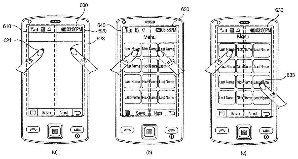
FIG. 12illustrates how to display a menu screen in response to a multi-site multi-touch input detected from an idle screen. Referring toFIGS. 12(a) and12(b), if a multi-site multi-touch input, which includes first and second touch inputs621and623detected from first and second sub-screens610and620, respectively, of an idle screen600, is detected from the idle screen600, a menu screen630may be displayed on the display module151. The user can set what menu screen should be displayed in response to a multi-site multi-touch input.
Referring toFIG. 12(c), if a touch input633that satisfies a predefined condition is detected from the menu screen630, another menu screen may be displayed on the display module151. Each menu icon displayed on the menu screen630may be selected or executed by a typical touch input that does not satisfy the predefined condition.
FIG. 13illustrates diagrams for explaining various operations that can be performed by the mobile terminal100in response to a single-site multi-touch input detected from an idle screen. Referring toFIG. 13(a), if a single-site multi-touch input, which includes first and second touch inputs661and663detected both from a first sub-screen of an idle screen640, is detected from the idle screen640, a ‘Modify Settings’ menu may be displayed on the display module151. Examples of settings information that can be modified using the ‘Modify Settings’ menu include, but are not restricted to, background settings information, control-related information, event-related information and other user settings information. Examples of the background settings information include, but are not restricted to, information regarding the enlargement or reduction of a background image, the replacement of a background image and entering into a background image gallery.
In the ‘Modify Settings’ menu, each item can be modified or set by a long touch input or by a multi-touch input and then a drag input. For example, referring toFIG. 13(b), if a drag input665is detected immediately after the second touch input663, an item designated by both the second touch input663and the drag input665may be modified or the modification of settings information may be completed.
(Embodiments Related to Camera Function)
FIG. 14illustrates a flowchart of a method of controlling the operation of a mobile terminal according to another embodiment of the present invention. Referring toFIG. 14, if a camera mode is selected in response to, for example, a user command addition, the controller180may display a preview screen showing a preview image provided by the camera module121on the display module151(S700).
Thereafter, if a multi-site multi-touch input is detected from the preview screen (S702), the controller180may switch the camera module121from a photo capture mode to a video recording mode and may control the camera module121to record a video (S704) until the multi-site multi-touch input is no longer detected from the preview screen (S706).
If the multi-site multi-touch input is no longer detected from the preview screen (S706), the controller180may display a menu for allowing the user to choose whether to save the recorded video on the display module151(S708). If the user chooses to save the recorded video (S710), the controller180may save the recorded video in the memory160as a file with a given name (S712).
If a single-site multi-touch input is detected from the preview screen, the preview image may be zoomed in or out, or a predefined function may be performed.
If a camera function other than capturing a video is selected from the preview screen (S714), the controller180may control the selected camera function to be performed (S716).
Operations5702through5716may be repeatedly performed until the user chooses to terminate the camera mode (S718).
According to this embodiment, it is possible to readily record a video in response to a multi-touch input detected from a preview screen.
FIG. 15illustrates a flowchart of a method of controlling the operation of a mobile terminal according to another embodiment of the present invention. Referring toFIG. 15, if a camera mode is selected in response to, for example, a user command addition, the controller180may display a preview screen showing a preview image provided by the camera module121on the display module151(S730).
Thereafter, if a single-site multi-touch input and then a drag input are detected in a row from the preview screen (S732), the controller180may display a panorama guide corresponding to the direction of the drag input (S734). For example, if a single-site multi-touch input and then a left-to-right drag are detected in a row from the preview screen, the controller180may display a left-to-right panorama guide. On the other hand, if a single-site multi-touch input and then a right-to-left drag are detected in a row from the preview screen, the controller180may display a right-to-left panorama guide.
A panorama mode is a mode for taking three or more pictures of the same place, stitching the three or more pictures into a panorama image and saving the panorama image. For this, a lattice guide may be displayed over the preview image. The lattice guide may also be useful for capturing a photo, capturing a plurality of photos in a row or capturing a self-portrait. In order to properly stitch a current image with a previous image in the panorama mode, the previous image may be partially displayed, instead of the panorama guide. In the panorama mode, not only landscape images but also portrait images can be stitched together.
Thereafter, if the user chooses to capture an image (S736), the controller180may control the camera module121to capture an image (S738). The captured image may be displayed on the display module151, instead of the preview screen.
On the other hand, if a multi-site multi-touch input is detected from the preview screen (S740), the controller180may determine that the user has chosen to capture an image, and may control the camera module121to capture an image (S742). That is, the controller180may interpret a multi-site multi-touch input detected from the preview screen as a command to capture an image.
If a camera function other than capturing an image is selected (S744), the controller180may control the selected camera function to be performed (S746). For example, if the user multi-touches an image listed in a camera album with two fingers and then drags the image with one of the two fingers, the image may be zoomed in or out according to the distance by which it is dragged.
Operations5732through5746may be repeatedly performed until the user chooses to terminate the camera mode (S748).
According to this embodiment, it is possible to display a panorama guide over a preview image or capture an image in response to a multi-touch input detected from the preview image.
The embodiments ofFIGS. 14 and 15will hereinafter be described in further detail with reference toFIGS. 16 and 17.
FIG. 16illustrates how to record a video in response to a multi-site multi-touch input. Referring toFIGS. 16(a) and16(b), if a multi-site multi-touch input, which includes first and second touch inputs821and823detected from first and second sub-screens810and820, respectively, of a preview screen800, is detected from the preview screen800, the camera module121may be switched to a video recording mode, and thus, a video recording screen830may be displayed on the display module151. Then, a video recording process may be performed until the multi-site multi-touch input is no longer detected. More specifically, the video recording process may be terminated when the multi-site multi-touch input is no longer detected or when another touch input is detected.
When the video recording process is terminated, a menu for allowing the user to choose whether to save the recorded video or cancel saving the recorded video or to perform an additional video recording process and save an additionally recorded video in connection with a previously recorded video may be displayed on the display module151. If the user chooses to perform an additional video recording process and save an additionally recorded video in connection with a previously recorded video, the controller180may properly stitch the previously recorded video and the additionally recorded video together.
FIG. 17(a) illustrates how to capture an image in response to a multi-site multi-touch input. Referring toFIG. 17(a), if a multi-site multi-touch input, which includes first and second touch inputs861and863detected from first and second sub-screens850and860, respectively, of a preview screen840, is detected from the preview screen840, an image capture process may be performed.
FIGS. 17(b) and17(c) illustrate how to provide a panorama guide in response to a single-site multi-touch input and a drag input. Referring toFIGS. 17(b) and17(c), if a single-site multi-touch input865and then a left-to-right drag input867are detected in a row from the preview screen840, a left-to-right panorama guide871may be displayed on the display module151. On the other hand, if a single-site multi-touch input and then a right-to-left drag input are detected in a row from the preview screen840, a right-to-left panorama guide may be displayed on the display module151.
In short, referring toFIGS. 16 and 17, it is possible to effectively control various camera operations in response to a multi-touch input detected from a preview screen.
(Embodiments Related to Multitasking)
FIG. 18illustrates a flowchart of a method of controlling the operation of a mobile terminal according to another embodiment of the present invention. Referring toFIG. 18, if an operation menu such as ‘New Message’ is selected in response to, for example, a user command, the controller180may display a document editor screen, which enables the user to create a new message or document, on the display module151(S900).
Thereafter, if a multi-site multi-touch input or a single-site multi-touch input is detected from the document editor screen (S902), the controller180may enter a screen division mode and may thus divide the screen of the display module151vertically into first and second sections, may display the document editor screen on the first section, and may display a display screen showing a first set of files that can be attached to any document in the document editor screen on the second section (S904).
The files displayed on the second section can be identified by their file names or icons.
Thereafter, if a user input with directivity such as a flick input or a touch-and-drag input is detected from the second section (S906), the controller180may either attach one of the files displayed on the second section to the document in the document editor window or display a second set of files, which is different from the first set of files, on the second section (S908).
For example, if one of the files displayed on the second section is touched and then flicked or dragged to the left, the corresponding file may be attached to the document in the document editor window. If a left-to-right flick is detected from the second section, a set of files, which is different from the first set of files, may be displayed on the second section. The term ‘flick input’ indicates, but is not restricted to, a user input generated by scratching the surface of the display module151lightly with a finger. A flick input and a typical touch input can be distinguished from each other by the duration for which the user touches the surface of the display module151with a finger.
Thereafter, if a touch input that satisfies a predefined condition is detected from one of the files displayed on the second section, the controller180may execute the file designated by the touch input in a multitasking manner (S912). The predefined condition may specify a touch duration, touch area or touch pressure that should be met. The file designated by the touch input may be executed in the background, and an operation screen relevant to the execution of the corresponding file may be displayed on the entire second section or on part of the second section.
Operations5906through5912may be repeatedly performed until the user chooses to terminate the screen division mode (S914). More specifically, the screen division mode may be terminated in response to a multi-site multi-touch input or a single-site multi-touch input or in response to the selection of a predefined menu icon.
Thereafter, if a user input other than a touch input, such as a key input, is detected (S916), the controller180may control an operation corresponding to the detected user input to be performed (S918).
According to this embodiment, it is possible to easily divide the screen of the display module151, attach a file to a document or email or perform various functions other than creating a document or email in a multitasking manner in response to a multi-touch input detected from a document editor screen.
FIG. 19illustrates a flowchart of a method of controlling the operation of a mobile terminal according to another embodiment of the present invention. Referring toFIG. 19, during multitasking, the controller180may divide the screen of the display module151vertically into first and second sections, may display a first operation screen relevant to the execution of a first function on the first section, and may display a second operation screen relevant to the execution of a second function on the second section (S930).
Thereafter, if a multi-touch input is detected from the boundary between the first and second operation screens (S932) and if a drag input is detected immediately after the multi-touch input (S934), the controller180may change the sizes of the first and second operation screens according to the direction and distance of the drag input (S936). For example, if the boundary between the first and second operation screens is multi-touched and then dragged to the right, the first operation screen may be enlarged by as much as the distance by which the boundary between the first and second operation screens is dragged, whereas the second operation screen may be reduced by as much as the distance by which the boundary between the first and second operation screens is dragged. On the other hand, if the boundary between the first and second operation screens is multi-touched and then dragged to the left, the second operation screen may be enlarged by as much as the distance by which the boundary between the first and second operation screens is dragged, whereas the first operation screen may be reduced by as much as the distance by which the boundary between the first and second operation screens is dragged.
On the other hand, if a multi-touch input is detected from the boundary between the first and second operation screens (S932) and if a flick input is detected immediately after the multi-touch input (S938), the controller180may display one of the first and second operation screens on the whole display module151(S940). For example, if the boundary between the first and second operation screens is multi-touched and then flicked to the left, the first operation screen may disappear, and the second operation screen may be displayed on the whole display module151. On the other hand, if the boundary between the first and second operation screens is multi-touched and then flicked to the right, the second operation screen may disappear, and the first operation screen may be displayed on the whole display module151.
If a user input with directivity such as a flick input or a touch-and-drag input is detected from the first section, the first operation screen may be replaced with another operation screen. Similarly, if a user input with directivity such as a flick input or a touch-and-drag input is detected from the second section, the second operation screen may be replaced with another operation screen.
If a user input, other than a multi-touch input, is detected (S942), the controller180may control an operation corresponding to the detected user input to be performed (S944).
According to this embodiment, it is possible to effectively change the size of each multitasking operation screen in response to a multi-touch input.
FIG. 20illustrates a flowchart of a method of controlling the operation of a mobile terminal according to another embodiment of the present invention. Referring toFIG. 20, the controller180may display a current operation screen corresponding to a current operation mode on the display module151(S960).
Thereafter, if an edge of the current operation screen is multi-touched and then dragged (S962) and if there is a function currently being executed in the background in a multitasking manner (S964), the controller180may additionally display an operation screen relevant to the function currently being executed in the background on the display module151in a size corresponding to the distance by which the current operation screen is dragged (S966).
If there is no function currently being executed in the background, the controller180may additionally display an additional operation screen relevant to the current operation screen on the display module151in a size corresponding to the distance by which the current operation screen is dragged (S968). Examples of the additional operation screen include, but are not restricted to, a menu screen relevant to the current operation screen and a display screen for modifying settings information such as background settings information, control-related information, event information or other user settings.
The operation screen relevant to the function currently being executed in the background or the additional operation screen relevant to the current operation screen may be expanded to the place where an edge of the current operation screen is dropped. Alternatively, if the distance by which an edge of the current operation screen is dragged exceeds a predefined level, the operation screen relevant to the function currently being executed in the background or the additional operation screen relevant to the current operation screen may be displayed on half the display module151or on the whole display module151.
If a user input, other than a multi-touch input, is detected (S970), the controller180may control an operation corresponding to the detected user input to be performed (S972).
According to this embodiment, it is possible to display an operation screen relevant to a function currently being executed in the background or an additional operation screen in response to a multi-touch input.
The embodiments ofFIGS. 18 through 20will hereinafter be described in further detail with reference toFIGS. 21 through 23.
FIG. 21illustrates how to enter a screen division mode in response to a multi-site multi-touch input. Referring toFIGS. 21(a) and21(b), if a multi-site multi-touch input, which includes first and second touch inputs1021and1023detected from first and second sub-screens1010and1020, respectively, of a document editor screen1000, is detected from the document editor screen1000, a display screen1030, which is divided vertically into first and second sub-screens1040and1050, may be displayed. Then, the document editor screen1000may be displayed in the first sub-screen1040, and a display screen showing a first set of files that can be attached to a document, if any, in the document editor screen1000or can be executed may be displayed on the second sub-screen1050.
If one of the files displayed on the second sub-screen1050is touched and then flicked or dragged to the left, the flicked or dragged file may be attached to the document in the document editor screen1000.
If the second sub-screen1050is flicked or dragged to the right, a different set of files from the first set of files may be displayed on the second sub-screen1050.
The type of files that can be displayed on the second sub-screen1050may vary according to the type of document editor screen or may be selected by the user. The screen division mode may also be entered in response to a single-site multi-touch input.
Referring toFIGS. 22(a) and22(b), if a multi-site multi-touch input, which includes first and second touch inputs1081and1083detected from the boundary between first and second sub-screens1070and1080of a display screen1060, and then a right-to-left drag input1087, which begins from the point where the second touch input1083is detected, are detected in a row from the display screen1060, the second sub-screen1080may be enlarged, whereas the first sub-screen1070may be reduced. Referring toFIG. 22(c), the first sub-screen1080may be enlarged to the full screen size of the display module151. In short, referring toFIG. 22, it is possible to effectively change the size of each sub-screen of an operation screen in response to a multi-touch input.
Referring toFIGS. 23(a) and23(b), if a multi-site multi-touch input, which includes first and second touch inputs1101and1103detected from an edge of an operation screen1100, and a left-to-right drag input1105, which begins from the point where the first touch input1101is detected, are detected in a row from the operation screen1100, an additional operation screen1110relevant to a current operation mode may also be displayed on the display module151. In this instance, if there is a function currently being executed in the background, an operation screen relevant to the function currently being executed in the background may be displayed on the display module151.
Referring toFIG. 23(c), the additional operation screen1110may be enlarged to the full screen size of the display module151in response to a drag input. In short, referring toFIG. 23, it is possible to additionally display an additional operation screen or an operation screen relevant to a function, if any, currently being executed in the background in response to a multi-touch input.
(Embodiments Related to Multimedia Player Function)
FIG. 24illustrates a flowchart of a method of controlling the operation of a mobile terminal according to another embodiment of the present invention. Referring toFIG. 24, the controller180may display an operation screen relevant to a multimedia player function (such as an MP3 player function) currently being performed in the background on the display module151in response to, for example, a user command (S1200).
Thereafter, if a single-site multi-touch input and a drag input are detected in a row from the display module151(S1202), the controller180may perform a predefined control operation for controlling the multimedia player function according to the direction of the drag input (S1204). For example, if a single-site multi-touch input and then a left-to-right drag input are detected in a row from the display module151, a subsequent multimedia file to a multimedia file currently being played may be played. If a single-site multi-touch input and then a left-to-right drag input are detected in a row from the display module151, a previous multimedia file to the multimedia file currently being played may be played. If a single-site multi-touch input and then a bottom-to-top drag input are detected in a row from the display module151, the volume of the multimedia file currently being played may be increased. If a single-site multi-touch input and then a top-to-bottom drag input are detected in a row from the display module151, the volume of the multimedia file currently being played may be reduced.
The user may set in advance what control operation should be performed in response to a drag input that follows a single-site multi-touch input. For convenience, when a single-site multi-touch input is detected, a guide menu may be additionally provided, specifying the types of control operations that can be performed in response to a drag input that follows the single-site multi-touch input. The guide menu may be configured to automatically disappear when the single-site multi-touch input is no longer detected.
If a user input, other than a multi-touch input, is detected (S1206), the controller180may perform an operation corresponding to the detected user input to be performed (S1208).
Operations S1202through S1208may be repeatedly performed until the user chooses to terminate the whole multimedia player function (S1210).
According to this embodiment, it is possible to effectively control a multimedia player function, which is being performed in the background, in response to a multi-touch input.
This embodiment can also be applied to the control of various functions associated with TV or radio broadcast reception, the setting of a Wireless Fidelity (WiFi) or Bluetooth function or the setting of an alarm, and etc.
The embodiment ofFIG. 24will hereinafter be described in further detail with reference toFIG. 25.FIG. 25illustrates how to control a multimedia player function in response to a multi-touch input. Referring toFIGS. 25(a) and25(b), if a single-site multi-touch input including first and second touch inputs1301and1303is detected from one region on an operation screen1300relevant to a multimedia player function currently being executed in the background, a guide menu specifying various control operations that can be performed in connection with the multimedia player function in response to drag inputs with different directions may be displayed. Thus, the user can easily determine in what direction to drag across the operation screen1300in order to perform a desired control operation for controlling the multimedia player function. The guide menu may be displayed semi-transparently over the operation screen1300.
Referring toFIG. 25(c), if a left-to-right drag input1305that begins from the point where the second touch input1303is detected is detected, information on a subsequent music file to that currently being played may be displayed, and the subsequent music file may be played.
In short, referring toFIG. 25, it is possible to control various operations associated with a multimedia player function in response to a multi-touch input when the multimedia player function is being performed in the background.
(Embodiment Related to Messaging)
FIG. 26illustrates a flowchart of a method of controlling the operation of a mobile terminal according to another embodiment of the present invention. Referring toFIG. 26, the controller180may display a first list screen showing a list of items (for example, a list of text messages) on the display module151in response to, for example, a user command (S1400).
Thereafter, if one of the text messages displayed on the first list screen is multi-touched (S1402), the controller180may enter a screen division mode, may divide the screen of the display module151vertically into first and second sections, may display the first list screen on the first section, and may display a display screen showing one or more additional functions that can be performed on the multi-touched text message on the second section (S1404). Examples of the additional functions include, but are not restricted to, replying to the multi-touched text message, saving the multi-touched text message, saving an image, if any, attached to the multi-touched text message, saving the phone number from which the multi-touched text message was sent, copying the multi-touched text message, viewing the content of the multi-touched text message or a file, if any, attached to the multi-touched text message, displaying information on the sender of the multi-touched text message, and displaying the content of a previous text message to the multi-touched text message and the content of a reply to the multi-touched text message.
Thereafter, if one of the additional functions is selected (S1406), the controller180may control the selected additional function to be performed (S1408).
Operations S1406and S1408may be repeatedly performed until the user chooses to terminate the screen division mode (S1410). The screen division mode may be terminated in response to a single-site multi-touch input or in response to the selection of a predetermined menu icon.
If more than one item on the first list screen is multi-touched (S1412), the controller180may enter the screen division mode, may divide the screen of the display module151vertically into first and second sections, may display the first list screen on the first section, and may display a second list screen on the second section (S1414). If the first list screen is a list screen showing a list of short message service (SMS) messages, the second list screen may be a list screen showing a list of multimedia messaging service (MMS) messages.
Thereafter, if there is a function selected from one of the first and second list screens (S1416), the controller180may control the selected function to be performed (S1418).
Operations S1416and S1418may be repeatedly performed until the user chooses to terminate the screen division mode (S1420).
If a user input, other than a multi-touch input, is detected (S1422), the controller180may control an operation corresponding to the detected user input to be performed (S1424).
According to this embodiment, it is possible to control various operations that can be performed in connection with a list of text messages in response to a multi-touch input.
The embodiment ofFIG. 26will hereinafter be described in further detail with reference toFIG. 27.
Referring toFIGS. 27(a) and27(b), if one of a plurality of text messages displayed on a list screen1500is selected by a multi-touch input including first and second touch inputs1521and1523, the screen of the display module151may be vertically divided into first and second sections. Then, a list screen1540, which is the same as the list screen1500, may be displayed on the first section, and a display screen1550showing a list of additional functions that can be performed on the selected text message may be displayed on the second section.
In addition, if more than one text message on the list screen1500is selected by a multi-touch input, the list screen1540may be displayed on the first section, and another list screen may be displayed on the second section. In short, referring toFIG. 27, it is possible to control various operations that can be performed in connection with a list of text messages in response to a multi-touch input.
(Embodiment Related to Unlocking and Other Embodiments)
Alternatively to the embodiments ofFIGS. 6,7,11,14,15,18through20,24and26, the mobile terminal100may be configured to be temporarily released from a lock state in response to a multi-touch input in order to perform a predefined function. More specifically, if a predetermined area on the display module151is multi-touched, the mobile terminal100may be temporarily released from the lock state and may thus be able to perform a predetermined function. Once the mobile terminal100finishes performing the predetermined function, the mobile terminal100may be automatically placed back in the lock state. Examples of the predetermined function that can be performed by temporarily releasing the mobile terminal100from the lock state include, but are not restricted to, checking the time, viewing text messages, viewing memos, using a calculator, and using an electronic dictionary.
During an augmented reality service, if more than one icon displayed on the display module151is selected by a multi-touch input, information indicating the distance between the selected icons may be displayed in one area on the display module151. Icons may be displayed differently from one another according to the distance of what they represent from the user. For example, the size of an icon representing an object or entity in the close vicinity of the user may be greater than the size of an icon representing an object or entity less close to the user. In addition, an icon representing an object or entity in the close vicinity of the user may be displayed in a darker color than an icon representing an object or entity less close to the user. This type of method of displaying the distance of objects or entities from the user using the size or color of icons can be applied to only a number of icons selected by the user or to all icons displayed on the display module151.
The mobile terminal according to the present invention and the method of controlling the operation of the mobile terminal according to the present invention are not restricted to the embodiments set forth herein. Therefore, variations and combinations of the embodiments set forth herein may fall within the scope of the present invention.
The present invention can be realized as code that can be read by a processor included in a mobile terminal and that can be written on a computer-readable recording medium. The computer-readable recording medium may be any type of recording device in which data is stored in a computer-readable manner. Examples of the computer-readable recording medium include a ROM, a RAM, a CD-ROM, a magnetic tape, a floppy disc, an optical data storage, and a carrier wave (e.g., data transmission through the internet). The computer-readable recording medium can be distributed over a plurality of computer systems connected to a network so that computer-readable code is written thereto and executed therefrom in a decentralized manner. Functional programs, code, and code segments needed for realizing the present invention can be easily construed by one of ordinary skill in the art.
As described above, according to the present invention, it is possible to control various operations performed by a mobile terminal using a multi-site multi-touch input and a single-site multi-touch input. In addition, it is possible to facilitate the manipulation of a mobile terminal by using a multi-site multi-touch input and/or a single-site multi-touch input together with a typical key input or a typical touch input.
While the present invention has been particularly shown and described with reference to embodiments thereof, it will be understood by those of ordinary skill in the art that various changes in form and details may be made therein without departing from the spirit and scope of the present invention as defined by the following claims.
Claims
- A method of controlling a mobile terminal, the method comprising: allowing, via a wireless communication unit of the mobile terminal, wireless communication with at least one other terminal;displaying, via a touch screen display unit of the mobile terminal, an idle screen having predefined first and second display portions in which a multi-touch input simultaneously in both the first and second display portions is defined as a multi-site multi-touch input and a multi-touch input simultaneously only in one of the first and second predefined display portions is defined as a single-site multi-touch input, the predefined first and second display portions being left and right halves of the touch screen display unit;receiving, via a controller of the mobile terminal, the multi-site multi-touch input in both of the first and second display portions;executing, via the controller, a first function based on the received multi-site multi-touch input, said first function displaying a first menu screen that includes a plurality of applications executable on the mobile terminal;receiving, via the controller, the single-site multi-touch input;and executing, via the controller, a second function different from the first function based on the received single-site multi-touch input.
- The method of claim 1 , wherein executing the first function further comprises: receiving, via the controller, another touch input that satisfies a predefined condition in at least one of the first and second display portions, the predefined condition being set regarding a touch duration or touch area;and in response to the another touch input, displaying a second menu screen that includes a plurality of different applications executable on the mobile terminal.
- The method of claim 1 , wherein the second function includes displaying a modify settings menu screen.
- The method of claim 3 , wherein the modify settings menu screen includes menus for modifying at least one of background setting information, control-related information, event-related information and user setting information of the mobile terminal.
- The method of claim 4 , further comprising: receiving another touch input on one of the menus included in the modify settings menu screen;and providing options for modifying the information for said one of the touched menus.
- The method of claim 5 , wherein the single-site multi-touch input includes a second touch input on said one of the menus, and wherein the method further comprises receiving a touch-and-drag action from said one of the menus displayed in the first display portion to the second display portion and modifying the information for said one of the touched menus based on the touch-and-drag action.
- The method of claim 1 , wherein the first menu screen includes home applications that can be executed on the mobile terminal and the second function includes displaying an environment settings menu for assigning different settings on the mobile terminal.
- The method of claim 1 , wherein the first menu screen includes a plurality of application icons respectively corresponding to the plurality of applications executable on the mobile terminal.
- The method of claim 8 , further comprising: receiving a first selection signal indicating a selection of a first application icon among the plurality of application icons;and executing the application corresponding to the selected first application icon.
- The method of claim 9 , further comprising: receiving a second selection signal indicating a selection of a second application icon among the plurality of application icons after the first application icon is selected;and executing the application corresponding to the selected second application icon after the application corresponding to the first application icon is executed.
- The method of claim 2 , further comprising: providing a menu for setting at least one of the first and second menu screens.
- A mobile terminal, comprising: a wireless communication unit configured to allow wireless communication with at least one other terminal;a touch screen display unit configured to display an idle screen having predefined first and second display portions in which a multi-touch input simultaneously in both the first and second display portions is defined as a multi-site multi-touch input and a multi-touch input simultaneously only in one of the first and second predefined display portions is defined as a single-site multi-touch input, the predefined first and second display portions being left and right halves of the touch screen display unit;and a controller configured to: receive the multi-site multi-touch input in both of the first and second display portions, execute a first function based on the received multi-site multi-touch input, said first function displaying a first menu screen that includes a plurality of applications executable on the mobile terminal, receive the single-site multi-touch input, and execute a second function different from the first function based on the received single-site multi-touch input.
- The mobile terminal of claim 12 , wherein the controller is further configured to receive another touch input that satisfies a predefined condition in at least one of the first and second display portions, the predefined condition being set regarding a touch duration or touch area, and in response to the another touch input, to display a second menu screen that includes a plurality of different applications executable on the mobile terminal.
- The mobile terminal of claim 12 , wherein the second function includes displaying a modify settings menu screen.
- The mobile terminal of claim 14 , wherein the modify settings menu screen includes menus for modifying at least one of background setting information, control-related information, event-related information and user setting information of the mobile terminal.
- The mobile terminal of claim 15 , wherein the controller is further configured to receive another touch input on one of the menus included in the modify settings menu screen, and provide options for modifying the information for said one of the touched menus.
- The mobile terminal of claim 16 , wherein the single-site multi-touch input includes a second touch input on said one of the menus, and wherein the controller is further configured to receive a touch-and-drag action from said one of the menus displayed in the first display portion to the second display portion and modify the information for said one of the touched menus based on the touch-and-drag action.
- The mobile terminal of claim 12 , wherein the first menu screen includes home applications that can be executed on the mobile terminal and the second function includes displaying an environment settings menu for assigning different settings on the mobile terminal, under control of the controller.
- The mobile terminal of claim 12 , wherein the first menu screen includes a plurality of application icons respectively corresponding to the plurality of applications executable on the mobile terminal.
- The mobile terminal of claim 19 , wherein the controller is further configured to receive a first selection signal indicating a selection of a first application icon among the plurality of application icons, and execute the application corresponding to the selected first application icon.
- The mobile terminal of claim 20 , wherein the controller is further configured to receive a second selection signal indicating a selection of a second application icon among the plurality of application icons after the first application icon is selected, and execute the application corresponding to the selected second application icon after the application corresponding to the first application icon is executed.
- The mobile terminal of claim 13 , wherein the controller is further configured to provide a menu for setting at least one of the first and second menu screens.
Disclaimer: Data collected from the USPTO and may be malformed, incomplete, and/or otherwise inaccurate.