U.S. Pat. No. 8,845,430
STORAGE MEDIUM HAVING STORED THEREON GAME PROGRAM, GAME APPARATUS, GAME SYSTEM, AND GAME PROCESSING METHOD
AssigneeNintendo Co., Ltd.
Issue DateJanuary 31, 2012
Illustrative Figure
Abstract
On the basis of data based on an attitude and/or a motion of a portable display apparatus body, an action of a player object placed in a virtual world is controlled, and on the basis of a position and/or an attitude of the player object, it is determined whether or not the player object has received an attack. Further, when the player object has received a predetermined attack, an attack effect image representing an effect of the predetermined attack is generated, and a first image is generated by superimposing the attack effect image on an image of the virtual world and displayed on the portable display apparatus. Then, the effect of the predetermined attack in an area in the attack effect image is repaired, the area overlapping a predetermined range whose center is a touch position on a touch panel.
Description
DETAILED DESCRIPTION OF NON-LIMITING EXAMPLE EMBODIMENTS With reference toFIG. 1, a game apparatus for executing a game program according to an exemplary embodiment and a game system including the game apparatus is described. Hereinafter, in order to provide a specific description, a stationary game apparatus body5is used as an example of the game apparatus, and a game system including the game apparatus body5is described.FIG. 1is an external view showing an example of the game system1including the stationary game apparatus body5.FIG. 2is a block diagram showing an example of the game apparatus body5. Hereinafter, the game system1is described. As shown inFIG. 1, the game system1includes a household television receiver (hereinafter referred to as a “monitor”)2which is an example of display means, and the stationary game apparatus3connected to the monitor2via a connection cord. The monitor2includes loudspeakers2afor outputting, in the form of sound, a sound signal outputted from the game apparatus3. Further, the game apparatus3includes: an optical disk4having stored therein a program, which is an example of the game program according to the exemplary embodiment; the game apparatus body5having a computer for executing the program stored in the optical disk4to display a game screen on the monitor2; a terminal apparatus6; a controller7for providing the game apparatus body5with operation information used to operate, for example, objects displayed on the display screen; and a board-type controller9. The game system1performs game processing on the game apparatus body5in accordance with a game operation using at least one of the terminal apparatus6, the controller7, and the board-type controller9, and displays a game image obtained by the game processing on the monitor2and/or the terminal apparatus6. The game apparatus body5is wirelessly connected to the terminal apparatus6, the controller7, and the board-type controller9so as to enable wireless communication therebetween. For example, the wireless communication is performed according to the Bluetooth (registered ...
DETAILED DESCRIPTION OF NON-LIMITING EXAMPLE EMBODIMENTS
With reference toFIG. 1, a game apparatus for executing a game program according to an exemplary embodiment and a game system including the game apparatus is described. Hereinafter, in order to provide a specific description, a stationary game apparatus body5is used as an example of the game apparatus, and a game system including the game apparatus body5is described.FIG. 1is an external view showing an example of the game system1including the stationary game apparatus body5.FIG. 2is a block diagram showing an example of the game apparatus body5. Hereinafter, the game system1is described.
As shown inFIG. 1, the game system1includes a household television receiver (hereinafter referred to as a “monitor”)2which is an example of display means, and the stationary game apparatus3connected to the monitor2via a connection cord. The monitor2includes loudspeakers2afor outputting, in the form of sound, a sound signal outputted from the game apparatus3. Further, the game apparatus3includes: an optical disk4having stored therein a program, which is an example of the game program according to the exemplary embodiment; the game apparatus body5having a computer for executing the program stored in the optical disk4to display a game screen on the monitor2; a terminal apparatus6; a controller7for providing the game apparatus body5with operation information used to operate, for example, objects displayed on the display screen; and a board-type controller9. The game system1performs game processing on the game apparatus body5in accordance with a game operation using at least one of the terminal apparatus6, the controller7, and the board-type controller9, and displays a game image obtained by the game processing on the monitor2and/or the terminal apparatus6. The game apparatus body5is wirelessly connected to the terminal apparatus6, the controller7, and the board-type controller9so as to enable wireless communication therebetween. For example, the wireless communication is performed according to the Bluetooth (registered trademark) standard or the IEEE 802.11n standard. The wireless communication, however, may be performed in accordance with other standards such as standards for infrared communication.
The optical disk4, typifying an information storage medium used for the game apparatus body5in an exchangeable manner, is detachably inserted in the game apparatus body5. The optical disk4has stored therein the game program to be performed by the game apparatus body5. The game apparatus body5has, on a front surface thereof, an insertion opening for the optical disk4. The game apparatus body5reads and executes the game program stored in the optical disk4inserted into the insertion opening to perform the game processing.
The monitor2is connected to the game apparatus body5via a connection cord. The monitor2displays a game image obtained by the game processing performed by the game apparatus body5. The monitor2includes the loudspeakers2a. The loudspeakers2aeach output a game sound obtained as a result of the game processing. In another embodiment, the game apparatus body5and a stationary display apparatus may be integrated with each other. The communication between the game apparatus body5and the monitor2may be wireless communication.
The game apparatus body5has mounted thereto a flash memory17(seeFIG. 2) which functions as a backup memory for fixedly storing data such as saved data. The game apparatus body5executes the game program or the like stored in the optical disk4, and displays a result thereof as a game image on the monitor2and/or the terminal apparatus6. The game program or the like to be executed may be stored in advance in the flash memory17as well as in the optical disk4. Further, the game apparatus body5may reproduce a state of a game played in the past, using the saved data stored in the flash memory17, and display an image of the game state on the monitor2and/or the terminal apparatus6. A user of the game apparatus3can enjoy the game progress by operating at least one of the terminal apparatus6, the controller7, and the board-type controller9while viewing the game image displayed on the monitor2and/or the terminal apparatus6.
The controller7and the board-type controller9each wirelessly transmit transmission data such as operation information, using, for example, the Bluetooth technology, to the game apparatus body5having a controller communication module19. The controller7is operation means for performing, for example, selection of options displayed on the display screen of the monitor2. The controller7includes a housing which is small enough to be held by one hand, and a plurality of operation buttons (including a cross key and the like) which are exposed at the surface of the housing. In addition, as is described later, the controller7includes an imaging information calculation section for taking an image viewed from the controller7. As exemplary imaging targets of the imaging information calculation section, two LED modules (hereinafter referred to as “markers”)8L and8R are provided in the vicinity of the display screen of the monitor2(above the screen inFIG. 1). Although details will be described later, a user (player) is allowed to perform a game operation while moving the controller7, and the game apparatus body5uses a marker8to calculate the movement, position, attitude and the like of the controller7. The marker8has two markers8L and8R at both ends thereof. Specifically, the marker8L (as well as the marker8R) includes one or more infrared LEDs (Light Emitting Diodes), and emits infrared light forward from the monitor2. The marker8is connected to the game apparatus body5, so that the game apparatus body5can control the infrared LEDs included in the marker8to be lit on or off. The marker8is a portable unit, so that the user is allowed to place the marker8in a given position. AlthoughFIG. 1shows a case where the marker8is placed on the monitor2, the location and direction of the marker8may be appropriately selected. Further, the controller7is capable of receiving, at a communication section, transmission data wirelessly transmitted from the controller communication module19of the game apparatus body5, to generate a sound or vibration based on the transmission data.
In another embodiment, the controller7and/or the board-type controller9may be wire-connected to the game apparatus body5. Further, in the exemplary embodiment, the game system1includes a controller7and a board-type controller9. The game apparatus body5, however, is capable of communicating with a plurality of controllers7and a plurality of board-type controllers9. Therefore, a plurality of players can play a game using a predetermined number of controllers7and board-type controller9simultaneously.
The controller7includes a housing which is formed by, for example, plastic molding, and has a plurality of operation sections (operation buttons) in the housing71. Then, the controller7transmits, to the game apparatus body5, operation data indicating the states of inputs provided to the operation sections (indicating whether or not each operation button has been pressed).
In addition, the controller7has the imaging information calculation section that analyzes image data of an image captured by capturing means and determines an area having a high brightness, and thereby calculates the position of the center of gravity, the size, and the like of the area. For example, the imaging information calculation section has capturing means fixed in the housing of the controller7, and uses as an imaging target a marker that outputs infrared light, such as a marker section65of the terminal apparatus6and/or the marker8. The imaging information calculation section calculates the position of the imaging target in a captured image captured by the capturing means, and transmits, to the game apparatus body5, marker coordinate data indicating the calculated position. The marker coordinate data varies depending on the direction (the angle of tilt) or the position of the controller7, and therefore, the game apparatus body5can calculate the direction and the position of the controller7using the marker coordinate data.
In addition, the controller7includes therein an acceleration sensor and/or a gyro sensor. The acceleration sensor detects the acceleration generated in the controller7(including the gravitational acceleration), and transmits, to the game apparatus body5, data indicating the detected acceleration. The acceleration detected by the acceleration sensor varies depending on the direction (the angle of tilt) or the movement of the controller7, and therefore, the game apparatus body5can calculate the direction and the movement of the controller7using the acquired acceleration data. The gyro sensor detects the angular velocities generated about three axes set in the controller7, and transmits, to the game apparatus body5, angular velocity data indicating the detected angular velocities. The acceleration detected by the gyro sensor varies depending on the direction (the angle of tilt) or the movement of the controller7, and therefore, the game apparatus body5can calculate the direction and the movement of the controller7using the acquired acceleration data. As described above, the user is allowed to perform a game operation by pressing any of the operation sections72provided on the controller7, and moving the controller7so as to change the position and the attitude (tilt) thereof.
The controller7has a loudspeaker and a vibrator. The controller7processes sound data transmitted from the game apparatus body5, and outputs sound corresponding to the sound data from the loudspeaker. Further, the controller7processes vibration data transmitted from the game apparatus body5, and generates vibration by actuating the vibrator in accordance with the vibration data. It should be noted that in the exemplary embodiment described later, it is possible to play a game without using the controller7. A detailed configuration of the board-type controller9will be described later.
The terminal apparatus6is a portable apparatus that is small enough to be held by the user, and the user is allowed to move the terminal apparatus6with hands, or place the terminal apparatus6at any location. Although a detailed configuration of the terminal apparatus6will be described later, the terminal apparatus6includes an LCD (Liquid Crystal Display)61as display means, and input means (a touch panel62, a gyro sensor604, and the like described later). The terminal apparatus6and the game apparatus body5(a terminal communication module28(seeFIG. 2)) are capable of communicating with each other wirelessly or wired. The terminal apparatus6receives, from the game apparatus body5, data of an image (e.g., a game image) generated in the game apparatus body5, and displays the image represented by the data on an LCD61. Although the LCD61is used as a display apparatus in the exemplary embodiment, the terminal apparatus6may include a given other display apparatus, such as a display apparatus utilizing EL (Electro Luminescence), for example. Further, the terminal apparatus6transmits, to the game apparatus body5having the terminal communication module28, operation data representing the content of an operation performed on the terminal apparatus6.
Next, with reference toFIG. 2, the internal configuration of the game apparatus body5is described.FIG. 2is a block diagram showing an example of the internal configuration of the game apparatus body5. The game apparatus body5includes a CPU (Central Processing Unit)10, a system LSI (Large Scale Integration)11, an external main memory12, a ROM/RTC (Read Only Memory/Real Time Clock)13, a disk drive14, an AV-IC (Audio Video-Integrated Circuit)15and the like.
The CPU10, serving as a game processor, executes a program stored in the optical disk4to perform a process. The CPU10is connected to the system LSI11. In addition to the CPU10, the external main memory12, the ROM/RTC13, the disk drive14, and the AV-IC15are connected to the system LSI11. The system LSI11performs processes such as control of data transmission between the respective components connected thereto, generation of an image to be displayed, and acquisition of data from an external apparatus. The internal configuration of the system LSI11will be described later. The external main memory12, which is a volatile memory, stores programs loaded from the optical disk4or the flash memory17, and stores various data. The external main memory12is used as a work area and a buffer area for the CPU10. The ROM/RTC13includes a ROM (so-called boot ROM) incorporating a program for booting the game apparatus body5, and a clock circuit (RTC) for counting time. The disk drive14reads, from the optical disk4, program data, texture data and the like, and writes the read data into an internal main memory35described below or the external main memory12.
The system LSI11includes an input/output processor (I/O processor)31, a GPU (Graphics Processor Unit)32, a DSP (Digital Signal Processor)33, a VRAM (Video RAM)34, and the internal main memory35. These components31to35are connected to each other via an internal bus (not shown).
The GPU32, which is a part of rendering means, generates an image in accordance with a graphics command (draw command) supplied from the CPU10. The VRAM34stores data (such as polygon data and texture data) used by the GPU32to execute the graphics command. When an image is generated, the GPU32generates image data using the data stored in the VRAM3. In the exemplary embodiment, the game apparatus body5may generate both a game image to be displayed on the monitor2and a game image to be displayed on the terminal apparatus6. Hereinafter, the game image to be displayed on the monitor2may be referred to as a “monitor game image”, and the game image to be displayed on the terminal apparatus6may be referred to as a “terminal game image”.
The DSP33, serving as an audio processor, generates sound data using sound data and sound waveform (tone quality) data stored in the internal main memory35and the external main memory12. In the exemplary embodiment, similarly to the game images, both a game sound to be output from the loudspeakers2aof the monitor2and a game sound to be output from the loudspeakers of the terminal apparatus6may be generated. Hereinafter, the game sound to be output from the monitor2may be referred to as a “monitor game sound”, and the game sound to be output from the terminal apparatus6may be referred to as a “terminal game sound”.
Among the image data and sound data generated by the game apparatus body5, the image data and sound data to be output to the monitor2are read by the AV-IC15. The AV-IC15outputs the read image data to the monitor2via an AV connector16, and outputs the read sound data to the loudspeakers2aincluded in the monitor2. Thereby, an image is displayed on the monitor2, and a sound is output from the loudspeakers2a.
Further, among the image data and sound data generated by the game apparatus body5, the image data and sound data to be output to the terminal apparatus6are transmitted to the terminal apparatus6by the I/O processor31or the like. Data transmission to the terminal apparatus6by the I/O processor31or the like will be described later.
The I/O processor31performs data reception and transmission with the components connected thereto, and download of data from an external apparatus. The I/O processor31is connected to the flash memory17, the network communication module18, the controller communication module19, an extension connector20, a memory card connector21, and a codec LSI27. An antenna23is connected to the controller communication module19. The codec LSI27is connected to the terminal communication module28, and an antenna29is connected to the terminal communication module28.
The game apparatus body5is connected to a network such as the Internet so as to communicate with external information processing apparatuses (for example, other game apparatuses or various servers). That is, the I/O processor31is connected to a network via the network communication module18and the antenna22so as to communicate with external information processing apparatuses connected to the network. The I/O processor31accesses the flash memory17at regular intervals so as to detect for data to be transmitted to the network. When data to be transmitted is detected, the data is transmitted to the network via the network communication module18and the antenna22. Further, the I/O processor31receives, via the network, the antenna22and the network communication module18, data transmitted from the external information processing apparatuses or data downloaded from a download server, and stores the received data in the flash memory17. The CPU10executes a program, and reads the data stored in the flash memory17to use the data for execution of the program. The flash memory17may store not only the data transmitted and received between the game apparatus body5and the external information processing apparatuses, but also saved data (result data or progress data of the process) of the game played with the game apparatus body5. Further, the flash memory17may store programs such as a game program.
The game apparatus body5can receive operation data from the controller7and/or the board-type controller9. That is, the I/O processor31receives, via the antenna23and the controller communication module19, operation data or the like transmitted from the controller7and/or the board-type controller9, and stores (temporarily) the data in a buffer region of the internal main memory35or the external main memory12. Similarly to the external main memory12, the internal main memory35may store a program loaded from the optical disk4or a program loaded from the flash memory17, and various data. The internal main memory35may be used as a work region or buffer region of the CPU10.
The game apparatus body5is capable of transmitting/receiving image data, sound data and the like to/from the terminal apparatus6. When transmitting a game image (terminal game image) to the terminal apparatus6, the I/O processor31outputs data of a game image generated by the GPU32to the codec LSI27. The codec LSI27performs a predetermined compression process on the image data supplied from the I/O processor31. The terminal communication module28performs wireless communication with the terminal apparatus6. Accordingly, the image data compressed by the codec LSI27is transmitted by the terminal communication module28to the terminal apparatus6via the antenna29. In the exemplary embodiment, the codec LSI27compresses the image data using a highly efficient compression technique, for example, the H.264 standard. The codec LSI27may adopt other compression techniques. When the communication rate is sufficiently high, uncompressed image data may be transmitted. The terminal communication module28is, for example, a Wi-Fi certified communication module. The terminal communication module28may perform wireless communication with the terminal apparatus6at a high speed using, for example, the technique of MIMO (Multiple Input Multiple Output) adopted in the IEEE 802.11n standard, or may use other communication techniques.
The game apparatus body5transmits, to the terminal apparatus6, sound data as well as the image data. That is, the I/O processor31outputs sound data generated by the DSP33to the terminal communication module28via the codec LSI27. The codec LSI27performs a compression process on the sound data in a similar manner to that for the image data. Any compression technique may be adopted for the sound data. In another embodiment, uncompressed sound data may be transmitted. The terminal communication module28transmits the compressed image data and sound data to the terminal apparatus6via the antenna29.
The game apparatus body5transmits, in addition to the image data and sound data, various control data to the terminal apparatus6, where necessary. The control data represent control instructions for the components included in the terminal apparatus6, such as an instruction to control on/off of a marker section (a marker section65shown inFIG. 5), and an instruction to control image taking of a camera (a camera66shown inFIG. 10). The I/O processor31transmits the control data to the terminal apparatus6in response to an instruction from the CPU5. In the exemplary embodiment, the codec LSI27does not perform a data compression process on the control data. Alternatively, in another embodiment, the codec LSI27may perform a compression process on the control data. The above data transmitted from the game apparatus body5to the terminal apparatus6may be encrypted where necessary, or may not be encrypted.
The game apparatus body5can receive various data from the terminal apparatus6. Although details will be described later, in the exemplary embodiment, the terminal apparatus6transmits operation data, image data, and sound data. The respective data transmitted from the terminal apparatus6are received by the terminal communication module28via the antenna29. The image data and sound data transmitted from the terminal apparatus6have been subjected to a similar compression process to that for the image data and sound data transmitted from the game apparatus body5to the terminal apparatus6. Accordingly, these image data and sound data are transmitted from the terminal communication module28to the codec LSI27, and subjected to a decompression process by the codec LSI27. The decompressed data are output to the I/O processor31. On the other hand, the operation data transmitted from the terminal apparatus6is smaller in amount than the image data and sound data, and therefore, the operation data does not need to be compressed. The operation data may be encrypted where necessary, or may not be encrypted. Accordingly, the operation data, which has been received by the terminal communication module28, is output to the I/O processor31via the codec LSI27. The I/O processor31stores (temporarily) the data received from the terminal apparatus6in the buffer region of the internal main memory35or the external main memory12.
The game apparatus body5is connectable to other devices and external storage media. That is, an extension connector20and a memory card connector21are connected to the I/O processor31. The expansion connector20is an interface connector as typified by a USB and an SCSI, and is capable of performing communication with the network, instead of the network communication module18, by connecting thereto a medium such as an external storage medium, a peripheral device such as another controller, or a wired communication connector. The memory card connector21is a connector for connecting thereto an external storage medium such as a memory card. For example, the I/O processor31accesses the external storage medium via the expansion connector20or the memory card connector21to save or read data.
The game apparatus body5includes (on the front main surface thereof, for example) a power button24, a reset button25, an insertion slot in which the optical disk4is inserted, an eject button26for ejecting the optical disk4from the insertion slot of the game apparatus body5, and the like. The power button24and the reset button25are connected to the system LSI11. When the power button24is turned on, the respective components of the game apparatus body5are supplied with power. When the reset button25is pressed, the system LSI11re-executes the boot program of the game apparatus body5. The eject button26is connected to the disk drive14. When the eject button26is pressed, the optical disk4is ejected from the disk drive14.
In another embodiment, some of the components of the game apparatus body5may be constituted as an extension device separated from the game apparatus body5. At this time, the extension device may be connected to the game apparatus body5via the extension connector20. Specifically, the extension device may include, for example, the codec LSI27, the terminal communication module28, and the antenna29, and may be detachably connected to the extension connector20. Thus, by connecting the extension device to the game apparatus body which does not have the above components, the game apparatus body can be made capable of communicating with the terminal apparatus6.
Next, with reference toFIGS. 3 through 5, the configuration of the terminal apparatus6is described.FIG. 3is a diagram showing an example of the external configuration of the terminal apparatus6. More specifically, (a) ofFIG. 3is a front view of the terminal apparatus6, (b) ofFIG. 3is a top view, (c) ofFIG. 3is a right side view, and (d) ofFIG. 3is a bottom view.FIG. 4shows an example of the state where a user holds the terminal apparatus6with both hands.
As shown inFIG. 3, the terminal apparatus6includes a housing60which generally has a horizontally long plate-like rectangular shape. The housing60is small enough to be held by the user. Therefore, the user is allowed to move the terminal apparatus6with hands, and change the location of the terminal apparatus6.
The terminal apparatus6includes an LCD61on a front surface of the housing60. The LCD61is provided near the center of the front surface of the housing60. Therefore, as shown inFIG. 4, the user, holding the housing60at portions to the left and right of the LCD61, is allowed to move the terminal apparatus6while viewing a screen of the LCD61.FIG. 4shows an example where the user holds the terminal apparatus6horizontally (i.e., with the longer sides of the terminal apparatus6being oriented horizontally) by holding the housing60at portions to the left and right of the LCD61. The user, however, may hold the terminal apparatus6vertically (i.e., with the longer sides of the terminal apparatus6being oriented vertically).
As shown in (a) ofFIG. 3, the terminal apparatus6includes, as operation means, a touch panel62on the screen of the LCD61. In the exemplary embodiment, the touch panel62is, but is not limited to, a resistive film type touch panel. However, a touch panel of a given type, such as electrostatic capacitance type, may be used. The touch panel62may be of single touch type or multiple touch type. In the exemplary embodiment, the touch panel62has the same resolution (detection accuracy) as that of the LCD61. The resolution of the touch panel62and the resolution of the LCD61, however, do not need to be the same. Although an input to the touch panel62is usually performed using a touch pen, in addition to the touch pen, a finger of the user may be used to perform an input to the touch panel62. The housing60may have an opening for accommodating the touch pen used to perform an operation to the touch panel62. The terminal apparatus6has the touch panel62, and therefore, the user is allowed to operate the touch panel62while moving the terminal apparatus6. That is, the user is allowed to directly (using the touch panel62) perform an input to the screen of the LCD61while moving the LCD61.
As shown inFIG. 3, the terminal apparatus6has, as operation means, two analog sticks63A and63B, and a plurality of operation buttons64A through64L. The analog sticks63A and63B are each a device for designating a direction. The analog sticks63A and63B are each configured such that a stick part thereof to be operated by a finger of the user is slidable or tiltable in a given direction (at a given angle in a given direction such as the upward, the downward, the leftward, the rightward, or the diagonal direction) with respect to the front surface of the housing60. The left analog stick63A is provided to the left of the screen of the LCD61, and the right analog stick63B is provided to the right of the screen of the LCD61. Therefore, the user is allowed to perform an input for designating a direction using the analog stick63A or63B with either the left or right hand. Further, as shown inFIG. 4, the analog sticks63A and63B are positioned so as to be operated by the user holding the left and right portions of the terminal apparatus6. Therefore, the user is allowed to easily operate the analog sticks63A and63B when the user holds and moves the terminal apparatus6.
The operation buttons64A through64L are each operation means for performing a predetermined input. As described below, the operation buttons64A through64L are positioned so as to be operated by the user holding the left and right portions of the terminal apparatus6(seeFIG. 4). Accordingly, the user is allowed to easily operate the operation means when the user holds and moves the terminal apparatus6.
As shown in (a) ofFIG. 3, among the operation buttons64A through64L, the cross button (direction input button)64A and the operation buttons64B through64H are provided on the front surface of the housing60. The operation buttons64A through64H are positioned so as to be operated by a thumb of the user (seeFIG. 4).
The cross button64A is provided to the left of the LCD61and beneath the left analog stick63A. That is, the cross button64A is positioned so as to be operated by the left hand of the user. The cross button64A is cross-shaped, and is capable of indicating an upward, a downward, a leftward, or a rightward direction. The operation buttons64B through64D are provided beneath the LCD61. The three operation buttons64B through64D are positioned so as to be operated by the right and left hands of the user. The four operation buttons64E through64H are provided to the right of the LCD61and beneath the right analog stick63B. That is, the four operation buttons64E through64H are positioned so as to be operated by the right hand of the user. Further, the four operation buttons64E through64H are positioned upward, downward, leftward, and rightward, respectively, with respect to a center position of the four operation buttons. Accordingly, the terminal apparatus6may cause the four operation buttons64E through64H to function as buttons which allow the user to designate an upward, a downward, a leftward, or a rightward direction.
As shown in (a), (b), and (c) ofFIG. 3, a first L button641and a first R button64J are provided on diagonal upper portions (an upper left portion and an upper right portion) of the housing60. Specifically, the first L button641is provided on the left end of the upper side surface of the plate-shaped housing60so as to protrude from the upper and left side surfaces. The first R button64J is provided on the right end of the upper side surface of the housing60so as to protrude from the upper and right side surfaces. In this way, the first L button641is positioned so as to be operated by the index finger of the left hand of the user, and the first R button64J is positioned so as to be operated by the index finger of the right hand of the user (seeFIG. 4).
As shown in (b) and (c) ofFIG. 3, leg parts68A and68B are provided so as to protrude from a rear surface (i.e., a surface reverse of the front surface on which the LCD61is provided) of the plate-shaped housing60, and a second L button64K and a second R button64L are provided so as to protrude from the leg parts68A and68B, respectively. Specifically, the second L button64K is provided at a slightly upper position on the left side (the left side as viewed from the front surface side) of the rear surface of the housing60, and the second R button64L is provided at a slightly upper position on the right side (the right side as viewed from the front-surface side) of the rear surface of the housing60. In other words, the second L button64K is provided at a position substantially opposite to the left analog stick63A provided on the front surface, and the second R button64L is provided at a position substantially opposite to the right analog stick63B provided on the front surface. The second L button64K is positioned so as to be operated by the middle finger of the left hand of the user, and the second R button64L is positioned so as to be operated by the middle finger of the right hand of the user (seeFIG. 4). Further, as shown in (c) ofFIG. 3, the leg parts68A and68B each have a surface facing obliquely upward, and the second L button64K and the second R button64L are provided on the oblique surfaces of the leg parts68A and68B, respectively. Thus, the second L button64K and the second R button64L have button surfaces facing obliquely upward. It is supposed that the middle finger of the user moves vertically when the user holds the terminal apparatus6, and therefore, the upward facing button surfaces allow the user to easily press the second L button64K and the second R button64L. Further, the leg parts68A and68B provided on the rear surface of the housing60allow the user to easily hold the housing60. Moreover, the operation buttons provided on the leg parts68A and68B allow the user to easily perform operation while holding the housing60.
In the terminal apparatus6shown inFIG. 3, the second L button64K and the second R button64L are provided on the rear surface of the housing60. Therefore, if the terminal apparatus6is placed with the screen of the LCD61(the front surface of the housing60) facing upward, the screen of the LCD61may not be perfectly horizontal. Accordingly, in another embodiment, three or more leg parts may be provided on the rear surface of the housing60. In this case, if the terminal apparatus6is placed on a floor with the screen of the LCD61facing upward, the three or more leg parts contact the floor. Thus, the terminal apparatus6can be placed with the screen of the LCD61being horizontal. Such a horizontal placement of the terminal apparatus6may be achieved by providing detachable leg parts on the rear surface of the housing60.
The respective operation buttons64A through64L are assigned functions, where necessary, in accordance with a game program. For example, the cross button64A may be used for direction designation operation, selection operation, and the like, and the operation buttons64E through64H may be used for determination operation, cancellation operation, and the like.
The terminal apparatus6includes a power button (not shown) for turning on/off the power of the terminal apparatus6. The terminal apparatus6may include an operation button for turning on/off screen display of the LCD61, an operation button for performing connection setting (pairing) with the game apparatus body5, and an operation button for adjusting the volume of loudspeakers (loudspeakers607shown inFIG. 5).
As shown in (a) ofFIG. 3, the terminal apparatus6includes a marker section (a marker section65shown inFIG. 5) including a marker65A and a marker65B, on the front surface of the housing60. For example, the marker section65is provided above the LCD61. The markers65A and65B are each constituted by one or more infrared LEDs, like the markers8L and8R of the marker8. The marker section65is used, like the marker8, for causing the game apparatus body5to calculate a movement or the like of the controller7with respect to the marker section65. The game apparatus body5is capable of controlling the infrared LEDs of the marker section65to be on or off.
The terminal apparatus6includes a camera66as imaging means. The camera66includes an image pickup element (e.g., a CCD image sensor or a CMOS image sensor) having a predetermined resolution, and a lens. For example, the camera66is provided on the front surface of the housing60. Accordingly, the camera66is capable of taking an image of the face of the user holding the terminal apparatus6. For example, the camera66is capable of taking an image of the user playing a game while viewing the LCD61.
The terminal apparatus6has a microphone (a microphone609shown inFIG. 5) as sound input means. A microphone hole60bis provided in the front surface of the housing60. The microphone609is embedded in the housing60at a position inside the microphone hole60b. The microphone609detects for a sound, such as user's voice, around the terminal apparatus6.
The terminal apparatus6has loudspeakers (loudspeakers607shown inFIG. 5) as sound output means. As shown in (d) ofFIG. 3, speaker holes60aare provided in the lower side surface of the housing60. A sound is output through the speaker holes60afrom the loudspeakers607. In the exemplary embodiment, the terminal apparatus6has two loudspeakers, and the speaker holes60aare provided at positions corresponding to a left loudspeaker and a right loudspeaker.
The terminal apparatus6includes an extension connector67for connecting another device to the terminal apparatus6. In the exemplary embodiment, as shown in (d) ofFIG. 3, the extension connector67is provided in the lower side surface of the housing60. Any device may be connected to the extension connection67. For example, a controller (a gun-shaped controller or the like) used for a specific game or an input device such as a keyboard may be connected to the extension connector67. If another device does not need to be connected, the extension connector67does not need to be provided.
In the terminal apparatus6shown inFIG. 3, the shapes of the operation buttons and the housing60, the number of the respective components, and the positions in which the components are provided are merely examples. The shapes, numbers, and positions may be different from those described above.
Next, with reference toFIG. 5, the internal configuration of the terminal apparatus6is described.FIG. 5is a block diagram showing an example of the internal configuration of the terminal apparatus6. As shown inFIG. 5, the terminal apparatus6includes, in addition to the components shown inFIG. 3, a touch panel controller601, a magnetic sensor602, a gyro sensor604, a user interface controller (UI controller)605, a codec LSI606, loudspeakers607, a sound IC608, a microphone609, a wireless module610, an antenna611, an infrared communication module612, a flash memory613, a power supply IC614, a battery615, and a vibrator619. These electronic components are mounted on an electronic circuit board and accommodated in the housing60.
The UI controller605is a circuit for controlling data input to various input/output sections and data output from various input/output sections. The UI controller605is connected to the touch panel controller601, the analog stick63(the analog sticks63A and63B), the operation button64(the operation buttons64A through64L), the marker section65, the magnetic sensor602, the acceleration sensor603, the gyro sensor604, and the vibrator619. Further, the UI controller605is connected to the codec LSI606and the extension connector67. The power supply IC614is connected to the UI controller605, so that power is supplied to the respective components through the UI controller605. The internal battery615is connected to the power supply IC614, so that power is supplied from the battery615. Further, a battery charger616or a cable, which is supplied with power from an external power supply, may be connected to the power supply IC614via a connector or the like. In this case, the terminal apparatus6can be supplied with power and charged from the external power supply using the battery charger616or the cable. Charging of the terminal apparatus6may be performed by setting the terminal apparatus6on a cradle (not shown) having a charging function.
The touch panel controller601is a circuit which is connected to the touch panel62and controls the touch panel62. The touch panel controller601generates a predetermined form of touch position data, on the basis of a signal from the touch panel62, and outputs the touch position data to the UI controller605. The touch position data represents coordinates of a position at which an input is performed on an input surface of the touch panel62. The touch panel controller601reads a signal from the touch panel62and generates touch position data every predetermined period of time. Further, various control instructions on the touch panel62are output from the UI controller605to the touch panel controller601.
The analog stick63outputs, to the UI controller605, stick data representing a direction in which the stick part operated by a finger of the user slides (or tilts), and the amount of the sliding (tilting). The operation button64outputs, to the UI controller605, operation button data representing an input state of each of the operation buttons64A through64L (whether or not the operation button is pressed).
The magnetic sensor602detects the magnitude and direction of a magnetic field to detect an orientation. Orientation data representing the detected orientation is output to the UI controller605. The UI controller605outputs, to the magnetic sensor602, a control instruction for the magnetic sensor602. Examples of the magnetic sensor602include: an MI (Magnetic Impedance) sensor, a fluxgate sensor, a hall sensor, a GMR (Giant Magneto Resistance) sensor, a TMR (Tunneling Magneto Resistance) sensor, and an AMR (Anisotropic Magneto Resistance) sensor. Any sensor, however, may be adopted as long as the sensor can detect an orientation. Strictly speaking, the obtained orientation data does not represent an orientation in a place where a magnetic field is generated in addition to the geomagnetism. Even in such a case, it is possible to calculate a change in the attitude of the terminal apparatus6because the orientation data changes when the terminal apparatus6moves.
The acceleration sensor603is provided inside the housing60. The acceleration sensor603detects the magnitudes of linear accelerations along three axial directions (the x-axis, y-axis, and z-axis directions shown in (a) ofFIG. 3). Specifically, in the acceleration sensor603, the long side direction of the housing60is defined as the x-axis direction (in the state where the marker section65is placed above the LCD61, the right direction along the long side direction when facing the display screen of the LCD61is defined as an x-axis positive direction), the short side direction of the housing60is defined as the y-axis direction (in the state where the marker section65is placed above the LCD61, the up direction along the short side direction when facing the display screen of the LCD61is a y-axis positive direction), and the direction orthogonal to the front surface of the housing60is defined as the z-axis direction (the perspective direction of the display screen of the LCD61is defined as a z-axis positive direction), thereby detecting the magnitudes of the linear accelerations in the respective axis directions. Acceleration data representing the detected accelerations is output to the UI controller605. The UI controller605outputs, to the acceleration sensor603, a control instruction for the acceleration sensor603. In the exemplary embodiment, the acceleration sensor603is, for example, an electrostatic capacitance type MEMS acceleration sensor. In another embodiment, however, another type of acceleration sensor may be used. Further, the acceleration sensor603may be an acceleration sensor for detecting the magnitude of acceleration in one axial direction or two axial directions.
The gyro sensor604is provided inside the housing60. The gyro sensor604detects the angular velocities about the three axes (the x, y, and z axes described above). Angular velocity data representing the detected angular velocities is output to the UI controller605. The UI controller605outputs, to the gyro sensor604, a control instruction for the gyro sensor604. Any number and any combination of gyro sensors may be used as long as the angular velocities about three axes are detected. The gyro sensor604may be constituted by a two-axis gyro sensor and a one-axis gyro sensor. Alternatively, the gyro sensor604may be a gyro sensor for detecting the angular velocity about one axis or two axes.
The vibrator619is, for example, a vibration motor or a solenoid. The vibrator619is connected to the UI controller605. The terminal apparatus6is vibrated by actuating the vibrator619in accordance with a control instruction outputted from the UI controller605to the vibrator619. The vibration of the terminal apparatus6is transmitted to the user's hand holding the terminal apparatus6. Thus, a so-called vibration-feedback game is achieved.
The UI controller605outputs, to the codec LSI606, the operation data including the touch position data, the stick data, the operation button data, the orientation data, the acceleration data, and the angular velocity data, which have been received from the respective components. If another device is connected to the terminal apparatus6through the extension connector67, data representing operation to said another device may be included in the operation data.
The codec LSI606is a circuit for performing a compression process on data to be transmitted to the game apparatus body5, and a decompression process on data transmitted from the game apparatus body5. The LCD61, the camera66, the sound IC608, the wireless module610, the flash memory613, and the infrared communication module612are connected to the codec LSI606. The codec LSI606includes a CPU617and an internal memory618. Although the terminal apparatus6is configured not to perform game processing, the terminal apparatus6may execute a program for managing the terminal apparatus6or a program for communication. For example, a program stored in the flash memory613is loaded into the internal memory618and executed by the CPU617when the terminal apparatus6is powered on, thereby starting up the terminal apparatus6. A part of the area of the internal memory618is used as a VRAM for the LCD61.
The camera66takes an image in accordance with an instruction from the game apparatus body5, and outputs data of the taken image to the codec LSI606. The codec LSI606outputs, to the camera66, a control instruction for the camera66, such as an instruction to take an image. The camera66is also capable of taking a moving picture. That is, the camera66is capable of repeatedly performing image taking, and repeatedly outputting image data to the codec LSI606.
The sound IC608is connected to the loudspeakers607and the microphone609. The sound IC608is a circuit for controlling input of sound data from the microphone609to the codec LSI606and output of sound data from the codec LSI606to the loudspeakers607. Specifically, when the sound IC608receives sound data from the codec LSI606, the sound IC608performs D/A conversion on the sound data, and outputs a resultant sound signal to the loudspeakers607to cause the loudspeakers607to output a sound. The microphone609detects sound (such as user's voice) propagated to the terminal apparatus6, and outputs a sound signal representing the sound to the sound IC608. The sound IC608performs A/D conversion on the sound signal from the microphone609, and outputs a predetermined form of sound data to the codec LSI606.
The codec LSI606transmits the image data from the camera66, the sound data from the microphone609, and the operation data from the UI controller605(terminal operation data), to the game apparatus body5through the wireless module610. In the exemplary embodiment, the codec LSI606subjects the image data and the sound data to a compression process similar to that performed by the codec LSI27. The compressed image data and sound data, and the terminal operation data are output to the wireless module610as transmission data. The antenna611is connected to the wireless module610, and the wireless module610transmits the transmission data to the game apparatus body5through the antenna611. The wireless module610has the same function as the terminal communication module28of the game apparatus body5. That is, the wireless module610has a function of connecting to a wireless LAN by a method based on, for example, the IEEE 802.11n standard. The data transmitted from the wireless module610may be encrypted where necessary, or may not be encrypted.
As described above, the transmission data transmitted from the terminal apparatus6to the game apparatus body5includes the operation data (terminal operation data), the image data, and the sound data. If another device is connected to the terminal apparatus6through the extension connector67, data received from said another device may be included in the transmission data. The infrared communication module612performs, with another device, infrared communication based on, for example, the IRDA standard. The codec LSI606may include, in the transmission data, data received by the infrared communication, and transmit the transmission data to the game apparatus body5, where necessary.
As described above, the compressed image data and sound data are transmitted from the game apparatus body5to the terminal apparatus6. These data are received by the codec LSI606through the antenna611and the wireless module610. The codec LSI606decompresses the received image data and sound data. The decompressed image data is output to the LCD61, and an image according to the image data is displayed on the LCD61. On the other hand, the decompressed sound data is output to the sound IC608, and a sound based on the sound data is output from the loudspeakers607.
When control data is included in the data received from the game apparatus body5, the codec LSI606and the UI controller605make control instructions for the respective components, according to the control data. As described above, the control data represents control instructions for the respective components (in the exemplary embodiment, the camera66, the touch panel controller601, the marker section65, the sensors602to604, the vibrator619, and the infrared communication module612) included in the terminal apparatus6. In the exemplary embodiment, the control instructions represented by the control data are considered to be instructions to start and halt (stop) the operations of the above components. That is, some components which are not used for a game may be halted to reduce power consumption. In this case, data from the halted components are not included in the transmission data transmitted from the terminal apparatus6to the game apparatus body5. The marker section65is constituted by infrared LEDs, and therefore, the marker section65is controlled by simply turning on/off the supply of power thereto.
As described above, the terminal apparatus6includes the operation means such as the touch panel62, the analog sticks63, and the operation buttons64. Alternatively, in another embodiment, the terminal apparatus6may include other operation means instead of or in addition to these operation means.
The terminal apparatus6includes the magnetic sensor602, the acceleration sensor603, and the gyro sensor604as sensors for calculating the movement (including the position and the attitude, or a change in the position or the attitude) of the terminal apparatus6. Alternatively, in another embodiment, the terminal apparatus6may include one or two of these sensors. In still another embodiment, the terminal apparatus6may include other sensors instead of or in addition to these sensors.
The terminal apparatus6includes the camera66and the microphone609. Alternatively, in another embodiment, the terminal apparatus6may not include the camera66and the microphone609, or may include either of the cameral66and the microphone609.
The terminal apparatus6includes the marker section65as a component for calculating the positional relation between the terminal apparatus6and the controller7(such as the position and/or the attitude of the terminal apparatus6as viewed from the controller7). Alternatively, in another embodiment, the terminal apparatus6may not include the marker section65. In still another embodiment, the terminal apparatus6may include other means as a component for calculating the above positional relation. For example, the controller7may include a marker section, and the terminal apparatus6may include an image pickup element. In this case, the marker8may include an image pickup element instead of an infrared LED.
Next, with reference toFIGS. 6 through 8, the configuration of the board-type controller9is described.FIG. 6is a perspective view illustrating an example of the appearance of the board-type controller9shown inFIG. 1. As shown inFIG. 6, the board-type controller9includes a platform9aon which a user stands (on which the user places their feet), and at least four load sensors94athrough94dfor detecting a load applied to the platform9a. Each of the load sensors94athrough94dis embedded in the platform9a(seeFIG. 7), and the positions where the load sensors94athrough94dare provided are indicated by dotted lines inFIG. 6. In the following description, the four load sensors94athrough94dmay be collectively referred to as a load sensor94.
The platform9ais formed in the shape of substantially a rectangular parallelepiped, and is in the shape of substantially a rectangle as viewed from the top. For example, the short side of the rectangular shape of the platform9ais approximately 30 cm, and the long side thereof is approximately 50 cm. The upper surface of the platform9ais flat, and has a pair of planes on which the user stands with the bottoms of their feet contacting thereto. Specifically, the upper surface of the platform9ahas a plane (a back-left region enclosed with a double line inFIG. 6) on which the user's left foot is placed, and a plane (a front-right region enclosed with a double line inFIG. 6) on which the user's right foot is placed. The platform9ahas, at four corners thereof, side surfaces each partially projecting outward in a cylindrical shape.
In the platform9a, the four load sensors94athrough94dare arranged at predetermined intervals. In the exemplary embodiment, the four load sensors94athrough94dare arranged on the periphery of the platform9a, more specifically, at the four corners of the platform9a. The intervals of the load sensors94athrough94dare appropriately set such that the load sensors94athrough94dcan accurately detect the intention of a game operation which is expressed by a manner of applying a load to the platform9aby the user.
FIG. 7shows an example of a cross-sectional view of the board-type controller9, taken along line A-A inFIG. 6, and an example of an enlarged view of a corner part where a load sensor94is arranged. InFIG. 7, the platform9aincludes a support plate90on which the user stands, and legs92. The load sensors94athrough94dare provided in positions where the legs92are provided. In the exemplary embodiment, the four legs92are provided at the four corners, and therefore, the four load sensors94athrough94dare also provided at the corresponding four corners. Each leg92is formed by plastic molding in the shape of substantially a cylinder with a base. Each load sensor94is located on a spherical part92aprovided on the base of the corresponding leg92. The support plate90is supported by the legs92via the load sensors94.
The support plate90includes an upper plate90aforming an upper surface and an upper side surface portion, a lower plate90bforming a lower surface and a lower side surface portion, and an intermediate plate90cprovided between the upper plate90aand the lower plate90b. The upper plate90aand the lower plate90bare formed by, for example, plastic molding, and are integrated using an adhesive or the like. The intermediate plate90cis, for example, formed of a single metal plate by press forming. The intermediate plate90cis fixed onto the four load sensors94athrough94d. The upper plate90ahas, on a lower surface thereof, a grid-patterned rib (not shown), and is supported by the intermediate plate90cvia the rib. Therefore, when the user stands on the platform9a, the load is transferred to the four legs92via the support plate90and the load sensors94athrough94d. As indicated by arrows inFIG. 7, a reaction from a floor, which is generated by the input load, is transferred from the legs92through the spherical parts92a, the load sensors94athrough94dand the intermediate plate90cto the upper plate90a.
Each load sensor94is, for example, a strain gauge (strain sensor) load cell, which is a load converter for converting an input load to an electrical signal. In the load sensor94, a strain-generating body95is deformed according to an input load, resulting in a strain. The strain is converted into a change of electrical resistance and then converted into a change of voltage by a strain sensor96attached to the strain-generating body95. Therefore, the load sensor94outputs, from an output terminal thereof, a voltage signal indicating the input load.
The load sensor94may be of other types, such as a tuning fork type, a string vibration type, an electrostatic capacitance type, a piezoelectric type, a magnetostrictive type, and a gyroscopic type.
Referring back toFIG. 6, the board-type controller9further includes a power button9c. When the power button9cis operated (e.g., when the power button9cis pressed) in the state where the board-type controller9is not activated, power is supplied to each of circuit components (seeFIG. 8) of the board-type controller9. There are, however, cases in which the board-type controller9is powered on in accordance with an instruction from the game apparatus body5and thereby supply of power to the circuit components is started. The board-type controller9may be automatically powered off when a state where the user does not stand thereon continues for a predetermined period of time (e.g., 30 sec) or more. Further, when the power button9cis again operated in the state where the board-type controller9is in the active state, the board-type controller9may be powered off to stop supply of power to the circuit components.
FIG. 8is a block diagram showing an example of an electrical configuration of the board-type controller9. InFIG. 8, flows of signals and data are indicated by solid arrows, and supply of power is indicated by dotted arrows.
As shown inFIG. 8, the board-type controller9includes a microcomputer100for controlling the operation thereof. The microcomputer100includes a CPU, a ROM, a RAM, and the like, which are not shown. The CPU controls the operation of the board-type controller9in accordance with a program stored in the ROM.
The power button9c, an AD converter102, a DC-DC converter104, and a wireless module106are connected to the microcomputer100. An antenna106ais connected to the wireless module106. The four load sensors94athrough94dare connected to the AD converter102via amplifiers108.
Further, the board-type controller9includes a battery110for supplying power to the circuit components. In another embodiment, an AC adapter may be connected to the board-type controller9instead of the battery110so that commercial power is supplied to the circuit components. In this case, instead of the DC-DC converter104, a power circuit, which converts alternating current into direct current and lowers and rectifies a direct-current voltage, needs to be provided in the board-type controller9. In the exemplary embodiment, power is supplied directly from the battery110to the microcomputer100and the wireless module106. In other words, power is constantly supplied from the battery110to the wireless module106and some components (such as the CPU) in the microcomputer100to detect whether or not the power button9cis turned on and whether or not a command that instructs power-on is transmitted from the game apparatus body5. On the other hand, power is supplied from the battery110through the DC-DC converter104to the load sensors94athrough94d, the AD converter102, and the amplifiers108. The DC-DC converter104converts a voltage value of direct current supplied from the battery110into a different voltage value, and supplies the resultant direct current to the load sensors94athrough94d, the AD converter102, and the amplifiers108.
Supply of power to the load sensors94athrough94d, the A/D converter102and the amplifiers108may be performed where necessary by the microcomputer100that controls the DC-DC converter104. Specifically, when the microcomputer100determines that it is necessary to operate the load sensors94athrough94dto detect a load, the microcomputer100may control the DC-DC converter104to supply power to the load sensors94athrough94d, the A/D converter102and the amplifiers108.
When power is supplied to the load sensors94athrough94d, the load sensors94athrough94deach output a signal indicating a load inputted thereto. These signals are amplified by the respective amplifiers108, and converted from analog signals into digital data by the A/D converter102. The digital data is input to the microcomputer100. The detected values of the load sensors94athrough94dare given identification information of the load sensors94athrough94d, so that the load sensors94athrough94dcan be identified from the corresponding detected values. Thus, the microcomputer100can acquire the data indicating the detected load values of the four load sensors94athrough94dat the same time.
On the other hand, when the microcomputer100determines that it is not necessary to operate the load sensors94athrough94d, i.e., when it is not the time for load detection, the microcomputer100controls the DC-DC converter104to stop supply of power to the load sensors94athrough94d, the A/D converter102, and the amplifiers108. Thus, the board-type controller9can operate the load sensors94athrough94dto detect a load or a distance only when it is required, resulting in a reduction in power consumption for load detection.
Load detection is typically required when the game apparatus body5(FIG. 1) needs to acquire load data. For example, when game apparatus body5requires load information, the game apparatus body5transmits an information acquisition command to the board-type controller9. When the microcomputer100receives the information acquisition command from the game apparatus body5, the microcomputer100controls the DC-DC converter104to supply power to the load sensors94athrough94dand the like, thereby detecting a load. On the other hand, when the microcomputer100does not receive a load acquisition command from the game apparatus body5, the microcomputer100controls the DC-DC converter104to stop supply of power to the load sensors94athrough94dand the like.
The microcomputer100may control the DC-DC converter104on the basis of a determination that the time of load detection arrives at predetermined intervals. When such periodic load detection is performed, information regarding the constant time period may be supplied and stored from the game apparatus body5to the microcomputer100of the board-type controller9when the game is started, or it may be preinstalled in the microcomputer100.
The data indicating the detected values from the load sensors94athrough94dare transmitted as board operation data (input data) for the board-type controller9from the microcomputer100via the radio module106and an antenna106bto the game apparatus body5. For example, when the microcomputer100has performed load detection according to a command from the game apparatus body5, the microcomputer100transmits the detected value data of the load sensors94athrough94dto the game apparatus body5on receipt of the detected value data from the A/D converter102. The microcomputer100may transmit the detected value data to the game apparatus body5at predetermined intervals. If the interval of the data transmission is longer than the interval of the load detection, data containing load values which have been detected at a plurality of detection times up to the subsequent time of transmission may be transmitted.
The wireless module106is set so as to perform communication according to the same wireless standard (the Bluetooth, wireless LAN, and the like) as that for the controller communication module19of the game apparatus body5. Accordingly, the CPU10of the game apparatus body5is allowed to transmit an information acquisition command to the board-type controller9through the controller communication module19and the like. Thus, the board-type controller9is allowed to receive the command from the game apparatus body5through the wireless module106and the antenna106a. Further, the board-type controller9is allowed to transmit the board operation data including the load detection values (or load calculation values) of the load sensors94athrough94dto the game apparatus body5.
For example, in a game which is performed on the basis of a simple sum of four load values detected by the four load sensors94athrough94d, the user is allowed to stand at a given position with respect to the four load sensors94athrough94dof the board-type controller9. That is, the user is allowed to stand on the platform9aat a given position and in a given direction to play a game. In some kinds of games, however, the direction of a load value detected by each of the four load sensors94viewed from the user needs to be identified. That is, a positional relation between the four load sensors94of the board-type controller9and the user needs to be recognized. In this case, for example, the positional relation between the four load sensors94and the user may be defined in advance, and the user may be supposed to stand on the platform9ain a manner which allows the predetermined positional relation. Typically, a positional relation in which two of the load sensors94athrough94dare present in front of, behind, to the right of, and to the left of the user standing in the center of the platform9a, i.e., a positional relation in which the user stands in the center of the platform9aof the board-type controller9, is defined. In this case, the platform9aof the board-type controller9is rectangular in shape as viewed from the top, and the power button9cis provided at one side (long side) of the rectangle. Therefore, it is ruled in advance that the user, using the power button9cas a guide, stands on the platform9asuch that the long side at which the power button9cis provided is located in a predetermined direction (front, rear, left or right). In this case, each of the load values detected by the load sensors94athrough94dis a load value of a predetermined direction (front right, front left, rear right, or rear left) as viewed from the user. Therefore, the board-type controller9and the game apparatus body5can find out a direction to which each detected load value corresponds as viewed from the user, on the basis of the identification information of the load sensors94contained in the detected load value data, and arrangement data indicating the positions or the directions of the load sensors94with respect to the user that is set (stored) in advance. As a result, it is possible to understand the intention of a game operation performed by the user, such as an operating direction, for example, a forward, a backward, or a leftward, a rightward direction, or a user's foot being lifted.
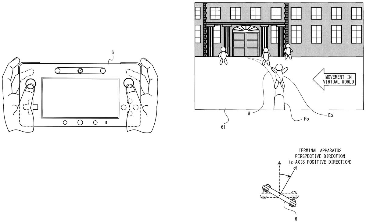
Next, with reference to the drawings, a description is given of an overview of the game processing performed by the game apparatus body5, before descriptions are given of specific processes performed by the game apparatus body5. It should be noted thatFIG. 9is a diagram showing an example of the state of a user performing an operation using the terminal apparatus6and the board-type controller9.FIG. 10Ais a diagram showing an example of an image displayed on the LCD61of the terminal apparatus6.FIG. 10Bis a diagram showing an example of an image displayed on the monitor2.FIG. 11is a diagram showing an example where the terminal apparatus6has been rotated (yawed) to the left and right, and an example of an image displayed on the LCD61.FIG. 12is a diagram illustrating examples of: the relationship between a terminal apparatus perspective direction projected onto a horizontal plane in real space and an operation indication direction projected onto a horizontal plane in a virtual world; and a player object Po controlled so as to be directed in a direction based on the operation indication direction.FIG. 13is a diagram illustrating examples of: the operation indication direction obtained by rotating (yawing) the terminal apparatus6to the left and right; and the player object Po controlled so as to be directed in a direction based on the operation indication direction.FIG. 14Ais a diagram illustrating an example of a barrel left-right operation range and a virtual camera left-right operation range that are set in the left-right direction in the virtual world (or in real space).FIG. 14Bis a diagram illustrating an example of a barrel up-down operation range and a virtual camera up-down operation range that are set in the up-down direction in the virtual world (or in real space).FIG. 15Ais a diagram showing an example of a dirt image in which dirt clumps Bd are represented so as to be attached to the player object Po.FIG. 15Bis a diagram showing an example of an image in which areas in the dirt clumps Bd represented so as to be attached to the player object Po are removed by a touch operation.
As shown inFIG. 9, the user performs an operation using the terminal apparatus6and the board-type controller9. The user performs the operation of changing the attitude and the direction of the terminal apparatus6, the operation of touching the touch panel62of the terminal apparatus6, and the operation of changing a load to be applied to the board-type controller9. Specifically, the user places one foot on the board-type controller9while holding the terminal apparatus6. Then, the user plays by taking action on the board-type controller9while viewing an image displayed on the monitor2or an image displayed on the LCD61of the terminal apparatus6(e.g., performing the operation of taking action so as to step with the one foot placed on the board-type controller9, thereby increasing and decreasing a weight to be put on the one foot placed on the board-type controller9), and also performing the operation of moving the terminal apparatus6and performing the operation of touching the touch panel62of the terminal apparatus6. Then, on the LCD61and the monitor2of the terminal apparatus6, game images are represented such that a player object Po takes action in a virtual world (e.g., the action of changing its direction, and the action of discharging a discharge object) in accordance with the direction and the attitude of the terminal apparatus6held by the user and the action taken by the user on the board-type controller9, and the attitude of a virtual camera set in the virtual world is changed in accordance with the direction of the player object Po. Further, it is possible to perform an operation on dirt clumps Bd represented so as to be attached to the player object Po, by performing a touch operation on the touch panel62of the terminal apparatus6.
As shown inFIG. 10A, on the LCD61of the terminal apparatus6, the state of a player object Po shooting a water cannon in a virtual world is displayed from the first-person point of view of the player object Po. In the example shown inFIG. 10A, the virtual world viewed from the first-person point of view is displayed that includes an end portion of the water cannon (an end portion of a barrel) operated by the player object Po, and the state of the water cannon discharging water W, which is an example of a discharge object, is displayed. Further, a plurality of enemy objects Eo are also placed in the virtual world, and the state of one of the enemy objects Eo throwing an enemy bomb object B at the player object Po is displayed. The virtual world viewed from the first-person point of view of the player object Po is thus displayed on the LCD61, whereby the user, viewing the display on the LCD61while holding the terminal apparatus6, can play a game from the same point of view as that of the player object Po. This makes it possible to provide a sense of presence in the virtual world.
In addition, as shown inFIG. 10B, also on the monitor2, the same virtual world as the virtual world displayed on the LCD61is displayed. In the example shown inFIG. 10B, the state of the virtual world viewed from a position behind, above, and far from the player object Po operating the water cannon is displayed together with the player object Po. The state of the virtual world viewed from a position behind, above, and far from the player object Po is thus displayed on the monitor2, whereby the user can easily understand the circumstance of the player object Po and the positional relationships among the player object Po and the enemy objects Eo, and another person viewing the state of the user playing the game can also enjoy viewing the attacking action of the player object Po.
It should be noted that in the example shown inFIG. 10B, on the monitor2, the state of the virtual world is displayed that is viewed from a position behind, above, and far from the player object Po. Alternatively, the virtual world viewed from another point of view may be displayed on the monitor2. The same virtual world may be displayed not only on the terminal apparatus6but also on the monitor2, and images of the virtual world that are different from each other in the point of view may be displayed, whereby, in accordance with the state of the operation or preference, the user can appropriately use either one of the images displayed on the two display apparatuses when performing an operation. For example, if, in contrast to the image viewed from the first-person point of view of the player object Po and displayed on the terminal apparatus6, a virtual camera (second virtual camera) for displaying the virtual world on the monitor2is set at a position away from the player object Po so that a range wider than the range of the virtual world displayed on the terminal apparatus6is displayed on the monitor2, the position of the virtual camera may not need to be behind, above, and far from the player object Po. Specifically, the virtual camera for displaying the virtual world on the monitor2may be set at a position of viewing the player object Po from a bird's-eye view or a position of looking down upon it.
It should be noted that in the example shown inFIG. 10B, on the monitor2, the state of the virtual world is displayed that is viewed from a position behind, above, and far from the player object Po. Alternatively, the virtual world viewed from another point of view may be displayed on the monitor2. The same virtual world may be displayed not only on the terminal apparatus6but also on the monitor2, and images of the virtual world that are different from each other in the point of view may be displayed, whereby, in accordance with the state of the operation or preference, the user can appropriately use either one of the images displayed on the two display apparatuses when performing an operation. For example, if, in contrast to the image viewed from the first-person point of view of the player object Po and displayed on the terminal apparatus6, a virtual camera (second virtual camera) for displaying the virtual world on the monitor2is set at a position away from the player object Po so that a range wider than the range of the virtual world displayed on the terminal apparatus6is displayed on the monitor2, the position of the virtual camera may not need to be behind, above, and far from the player object Po. Specifically, the virtual camera for displaying the virtual world on the monitor2may be set at a position of viewing the player object Po from a bird's-eye view or a position of looking down upon it.
For example, as described above, the board-type controller9outputs detected load values based on the action taken by the user on the board-type controller9. Then, the use of the detected load values makes it possible to calculate the total load applied to the board-type controller9. The use of the total load makes it possible to estimate whether the user is putting weight on the board-type controller9, or is decreasing the weight put on the board-type controller9. Further, the use of the total load also makes it possible to calculate the magnitude of the load applied to the board-type controller9by the user, and the amount of change in the load applied to the board-type controller9. The action of the player object Po discharging the discharge object is set in accordance with the action of the user thus estimated on the board-type controller9.
In addition, in accordance with the attitude (direction) of the terminal apparatus6held by the user, the direction in which the player object Po views the virtual world (i.e., the forward direction of the player object Po in the virtual world; the direction of the line of sight of a virtual camera placed at the first-person point of view of the player object Po) changes, and also the direction in which the player object Po discharges the discharge object (e.g., the water W) (the direction of the barrel of the water cannon) changes. For example, in accordance with the user directing the back surface of the terminal apparatus6upward, downward, leftward, and rightward, that is, directing the z-axis positive direction, which is the perspective direction of the LCD61(a terminal apparatus perspective direction), upward, downward, leftward, and rightward, the direction of the player object Po in the virtual world changes upward and leftward and to the left and right, and also the direction in which the water cannon discharges the discharge object changes upward and leftward and to the left and right in the virtual world. Further, in accordance with the user directing the terminal apparatus perspective direction of the terminal apparatus6upward, downward, leftward, and rightward, also the direction of the line of sight of the virtual camera changes upward and leftward and to the left and right. Consequently, also a game image displayed on the LCD61and viewed from the first-person point of view of the player object Po changes in accordance with the change in the direction of the line of sight. For example, as shown inFIG. 11, when the user has changed the direction of the terminal apparatus6such that the terminal apparatus perspective direction is directed rightward, the direction of the player object Po and the direction of the barrel of the water cannon in the virtual world change to the right, and also the direction of the line of sight of the virtual camera in the virtual world changes to the right by the same angle. As is clear by comparingFIGS. 11and10A, this results in causing the virtual world to be displayed on the LCD61so as to scroll to the left, and causing the barrel of the water cannon to be displayed at a fixed position on the LCD61so as to have the same attitude. Then, if the water W is continuing to be discharged from the barrel of the water cannon, display is performed on the LCD61such that the water W is discharged in a meandering manner in the virtual world in accordance with the change in the direction of the barrel.
FIGS. 12 and 13each show the attitude of the terminal apparatus6that is obtained by looking down upon real space, and the attitudes of the player object Po and the virtual camera that are obtained by looking down upon the virtual world. As shown inFIG. 12, a virtual camera (first virtual camera) for generating the virtual world to be displayed on the LCD61is placed at the first-person point of view of the player object Po that operates the water cannon in the virtual world. Then, an operation indication direction is calculated by reflecting on the virtual world the direction of the terminal apparatus perspective direction of the terminal apparatus6(the z-axis positive direction) in real space, and the direction of the player object Po and the direction of the barrel are set so as to coincide with the operation indication direction. Further, the attitude of the virtual camera is controlled such that the direction that coincides with the operation indication direction (i.e., the direction of the barrel) is the direction of the line of sight of the virtual camera (the Z-direction shown in the figures). The operation indication direction obtained by reflecting the terminal apparatus perspective direction on the virtual world is thus set so as to coincide with the direction of the line of sight of the virtual camera, whereby the direction in which the terminal apparatus6is directed upward, downward, leftward, and rightward in real space coincides with the direction in which the virtual camera is directed upward, downward, leftward, and rightward in the virtual world. This makes it possible to display on the LCD61an image as if peeping at the virtual world using the LCD61as a peep window.
The case is considered where the user has changed the direction of the terminal apparatus6such that the terminal apparatus perspective direction is directed rightward (the direction A shown inFIG. 12). For example, as shown inFIG. 13, the case is considered where the direction of the terminal apparatus6has changed such that the terminal apparatus perspective direction is directed in the direction A and by an angle B. In this case, the operation indication direction changes in the direction A and by the angle B also in the virtual world, in a similar manner to the change in the terminal apparatus perspective direction in real space. Then, also the direction of the player object Po and the direction of the barrel of the water cannon operated by the player object Po change about a predetermined position in the virtual world (e.g., the position of the player object Po, i.e., the position of the first-person point of view where the virtual camera is placed) in the direction A, which is the same as that of the change in the operation indication direction, and by the angle B. Further, also the direction of the line of sight of the virtual camera changes about a predetermined position in the virtual world (e.g., the position of the point of view of the virtual camera) in the direction A, which is the same as that of the change in the operation indication direction, and by the angle B.
Here, the range where the user is allowed to change the direction of the player object Po and the direction of the barrel of the water cannon may be limited in a predetermined range in advance. For example, as shown inFIG. 14A, a barrel left-right operation range, where the barrel can change its direction to the left and right in the virtual world, is set to a predetermined angular range about a virtual world reference direction (e.g., a range of 90° in total, which includes 45° to both the left and right of the virtual world reference direction, or a range of 180° in total, which includes 90° to both the left and right of the virtual world reference direction). It should be noted that the virtual world reference direction is a direction indicating the forward direction of the virtual world that corresponds to the forward direction of the user in real space (a real space reference direction), and is set, as an example, in accordance with an operation of the user. Further, as shown inFIG. 14B, a barrel up-down operation range, where the barrel can change its direction upward and downward in the virtual world, is set to a predetermined angular range with respect to the horizontal direction in the virtual world (the horizontal direction in real space) (e.g., a range of 55° in total, which includes 45° in the elevation direction from the horizontal direction in the virtual world and 10° in the depression direction from the horizontal direction in the virtual world). Then, if the operation indication direction is set outside the barrel left-right operation range and/or outside the barrel up-down operation range, the direction of the barrel is set in the barrel left-right operation range and/or in the barrel up-down operation range so as to be closest to the operation indication direction.
On the other hand, the range where the user is allowed to change the direction of the line of sight of the virtual camera may not need to be limited. For example, as shown inFIG. 14A, a virtual camera left-right operation range, where the direction of the line of sight of the virtual camera can be changed to the left and right, can be set in all directions. Further, as shown inFIG. 14B, also a virtual camera up-down operation range, where the direction of the line of sight of the virtual camera can be changed upward and downward, can be set in all directions. Accordingly, if the operation indication direction is set outside the barrel left-right operation range and/or outside the barrel up-down operation range, the direction of the barrel is set in the barrel left-right operation range and/or in the barrel up-down operation range, while the direction of the line of sight of the virtual camera is set so as to be the same as the operation indication direction. That is, when the user has directed the terminal apparatus6in the direction in which the operation indication direction is calculated so as to be outside the barrel left-right operation range and/or outside the barrel up-down operation range, the virtual world is displayed on the LCD61such that the direction of the line of sight of the virtual camera is different from the forward direction of the player object Po and the direction of the barrel.
For example, acceleration data or angular velocity data based on the motion and a change in the attitude of the terminal apparatus6is output from the terminal apparatus6. Then, the direction of the gravitational acceleration applied to the terminal apparatus6can be calculated using the acceleration indicated by the acceleration data. This makes it possible to estimate the attitude of the terminal apparatus6with respect to the vertical direction in real space. Further, the use of the angular velocity and/or the dynamic acceleration applied to the terminal apparatus6using the angular velocity indicated by the angular velocity data and/or the acceleration indicated by the acceleration data, makes it possible to estimate a change in the attitude of the terminal apparatus from its initial attitude in real space (i.e., a change in direction) using the angular velocity and/or the dynamic acceleration. In accordance with the thus estimated change in the attitude of the terminal apparatus6(a change in direction), the action of the player object Po (the forward direction of the player object Po and the direction of the barrel) and the attitude (the direction of the line of sight) of the virtual camera are set.
As described above, the user can change the action of the player object Po and the attitude of the virtual camera on the basis of the direction and the attitude of the terminal apparatus6held by the user. For example, in accordance with the direction and the attitude of the terminal apparatus6held by the user, the direction of the player object Po and the direction of the barrel change, and also the direction in which the discharge object is to be discharged from the barrel (a discharge direction) changes. As an example, as a result of the user directing the terminal apparatus6upward, downward, leftward, and rightward (i.e., pitching and yawing the terminal apparatus6), the direction of the player object Po and the direction of the barrel change in conjunction with the change in the direction of the terminal apparatus6, and also the discharge direction changes. Specifically, when the user has changed the direction of the terminal apparatus6so as to direct the back surface of the terminal apparatus6upward (i.e., pitch the terminal apparatus6in the elevation direction), the direction of the player object Po and the direction of the barrel change upward in the virtual world within the barrel up-down operation range. Further, when the user has changed the direction of the terminal apparatus6so as to direct the back surface of the terminal apparatus6leftward (i.e., yaw the terminal apparatus6to the left), the direction of the player object Po and the direction of the barrel change to the left in the virtual world within the barrel left-right operation range. By thus bringing the attitude and the direction of the terminal apparatus6in conjunction with the direction of the barrel, the user can perform an operation having verisimilitude as if the user themselves is moving the water cannon (barrel) using the terminal apparatus6. Further, as described above, the virtual camera is set at the first-person point of view of the player object Po that operates the water cannon, and the direction of the line of sight of the virtual camera changes in accordance with the direction and the attitude of the terminal apparatus6held by the user. By thus bringing the attitude and the direction of the terminal apparatus6in conjunction with the attitude and the direction of the virtual camera, the user can enjoy a feeling as if the user themselves is the player object Po that operates the water cannon, and can also enjoy a feeling as if peeping at the virtual world through the LCD61of the terminal apparatus6. Further, in the exemplary game described above, in accordance with the user applying a load to the board-type controller9, the action of discharging the discharge object from the water cannon is taken. Then, the details of the discharge object to be discharged (e.g., the presence or absence of the discharge of the discharge object, the amount of discharge and the discharge velocity in and at which the discharge object is to be discharged, and the type of the discharge object) are determined in accordance with the load applied to the board-type controller9, thereby enabling an analog operation. That is, the user is provided, by an image displayed on the LCD61, with a feeling as if being in the virtual world, and is additionally provided, by an analog operation using the board-type controller9, with an operation feeling as if the user themselves is operating a water cannon in real space. This enhances the feeling as if being in the virtual world.
It should be noted that the player object Po may be caused to move in the virtual world on the basis of the attitude and the motion of the terminal apparatus6. For example, a moving angle and a moving distance are calculated on the basis of changes in the attitude and the motion of the terminal apparatus6. Then, the player object Po that operates the water cannon is caused to move in the virtual world in accordance with the moving angle and the moving distance, and the first virtual camera is also caused to move in accordance with the movement of the player object Po.
As shown inFIG. 15A, the case is considered where an enemy bomb object B thrown by an enemy object Eo has hit the player object Po. To represent the state of the player object Po being soiled by the hitting of the enemy bomb object B, a dirt clump Bd based on the enemy bomb object B is represented so as to be attached on the surface of the LCD61. The attachment of the dirt clump Bd, as shown inFIG. 15A, hinders the field of view toward the virtual world using the LCD61. This creates a disadvantage for the user to play the game.
It is possible to remove the dirt clump Bd attached to the surface of the LCD61by performing a touch operation on the touch panel62of the terminal apparatus6. For example, as shown inFIG. 15B, when the user has performed the touch operation on the touch panel62that covers the surface of the LCD61, areas in dirt clumps Bd attached to the surface of the LCD61are removed, the areas corresponding to the touched position. As an example, when the areas in the dirt clumps Bd are removed, a predetermined range whose center is the touch position at which the user has touched the touch panel62is removed from the surface of the LCD61. Accordingly, when the user has performed the touch operation so as to drag the touch panel62(e.g., performed the touch operation so as to trace the dashed line shown inFIG. 15B), the areas in the dirt clumps Bd corresponding to the line on which the drag has been performed, or corresponding to an area having a predetermined line width with respect to the line, are removed from the surface of the LCD61. It should be noted that the action of removing the dirt clumps Bd attached to the surface of the LCD61can be considered as the action of the player object Po removing the dirt clumps Bd attached to the player object Po itself. Thus, in this case, the user causes the player object Po to take action by operating the touch panel62of the terminal apparatus6.
Next, the game processing performed by the game system1is described in detail. First, with reference toFIG. 15, main data used in the game processing is described.FIG. 15is a diagram showing an example of main data and programs that are stored in a main memory of the game apparatus body5.
As shown inFIG. 16, in a data storage area of the main memory, the following are stored: board operation data Da; terminal operation data Db; load value data Dc; terminal apparatus direction/attitude data Dd; operation direction data De; barrel direction data Df; discharge object data Dg; enemy bomb object data Dh; virtual camera data Di; image data Dh; and the like. It should be noted that the main memory appropriately stores, as well as the data shown inFIG. 16, data used for the game processing, such as image data of various objects displayed on the monitor2and the LCD61, and sound data used for the game. Further, in a program storage area of the main memory, various programs Pa included in the game program are stored.
As the board operation data Da, a series of operation information (board operation data) transmitted as transmission data from the board-type controller9is stored, and updated to the latest board operation data. For example, the board operation data Da includes load data Da1and the like. The load data Da1is data indicating load values detected by the load sensors94athrough94dof the board-type controller9.
As the terminal operation data Db, a series of operation information (terminal operation data) transmitted as transmission data from the terminal apparatus6is stored, and updated to the latest terminal operation data. For example, the terminal operation data Db includes acceleration data Db1, angular velocity data Db2, touch position data Db3, and the like. The acceleration data Db1is data indicating an acceleration (an acceleration vector) detected by the acceleration sensor603. For example, the acceleration data Db1represents a three-dimensional acceleration vector whose components are accelerations in the three axial (x-axis, y-axis, and z-axis) directions shown inFIG. 3. In another embodiment, the acceleration data Db1may represent accelerations in given one or more directions. The angular velocity data Db2is data representing an angular velocity detected by the gyro sensor604. For example, the angular velocity data Db2represents angular velocities about the three axes (x-axis, y-axis, and z-axis) shown inFIG. 3. In another example, the angular velocity data Db2may represent angular velocities about given one or more axes. The touch position data Db3is data representing the coordinates of the position at which an input has been provided on the input surface of the touch panel62.
It should be noted that the game apparatus body5sequentially receives the data (e.g., the data indicating the detected load values, the acceleration, and the angular velocity) included in the operation information transmitted from the controller7, the board-type controller9, and the terminal apparatus6at predetermined intervals (e.g., at intervals of 1/200 seconds). For example, the received data is sequentially stored in the main memory by the I/O processor31. In a processing flow described later, the CPU10reads the latest board operation data and the latest terminal operation data from the main memory every frame period (e.g., 1/60 seconds), to thereby update the board operation data Da and the terminal operation data Db.
In addition, the operation information transmitted from the controller7, the board-type controller9, and the terminal apparatus6at the predetermined intervals may be temporarily stored in the buffer (not shown) included in the controller communication module19or the terminal communication module28. In this case, the data stored in the buffer is read every frame period, and the board operation data Da (e.g., the load data Da1) or the terminal operation data Db (e.g., the acceleration data Db1, the angular velocity data Db2, and the touch position data Db3) in the main memory is updated for use. At this time, the cycle of receiving the operation information is different from the processing cycle, and therefore, a plurality of pieces of information received at a plurality of times are stored in the buffer. The processing may be performed using only the latest operation information among the plurality of pieces of operation information received at the plurality of times. Alternatively, the processing may be performed using a representative value (e.g., an average value) of the pieces of operation information received at the plurality of times. Yet alternatively, the processing may be performed multiple times so as to correspond to the number of the pieces of operation information received at the plurality of times.
The load value data Dc is an aggregate of data indicating the load values detected by the board-type controller9. For example, the load value data Dc is an aggregate of data indicating the sum of the load values (the total load value) detected by the load sensors94athrough94d. Specifically, the load value data Dc is an array of data indicating the total load values within a predetermined period that are chronologically calculated, and the data indicating the total load values is chronologically stored in the elements of the array.
The terminal apparatus direction/attitude data Dd includes real space reference direction data Dd1, current direction data Dd2, and the like. The real space reference direction data Dd1is data indicating a reference direction (the attitude; the real space reference direction) of the terminal apparatus6in real space. The current direction data Dd2is data indicating the current direction and attitude of the terminal apparatus6in real space. In the exemplary embodiment, the real space reference direction data Dd1and the current direction data Dd2are subjected to various corrections when set. For example, the real space reference direction data Dd1and the current direction data Dd2are calculated on the basis of the acceleration data Db1and the angular velocity data Db2that are included in the terminal operation data Db. It should be noted that the method of calculating the real space reference direction and the current direction will be described later.
The operation direction data De includes virtual world reference direction data De1, operation indication direction data De2, and the like. The virtual world reference direction data De1is data indicating the virtual world reference direction set in the virtual world. The operation indication direction data De2is data indicating the operation indication direction currently indicated in the virtual world by the user. It should be noted that the method of calculating the virtual world reference direction and the operation indication direction will be described later.
The barrel direction data Df includes barrel left-right direction data Df1, barrel up-down direction data Df2, and the like. The barrel left-right direction data Df1is data indicating the left-right direction of the barrel of the water cannon in the virtual world. The barrel up-down direction data Df2is data indicating the up-down direction of the barrel of the water cannon in the virtual world.
The discharge object data Dg includes object type data Dg1, amount of discharge data Dg2, discharge vector data Dg3, position data Dg4, and the like, for each discharge object present in the virtual world. The object type data Dg1is data indicating the type (e.g., the water W or the large ball) of the discharge object to be discharged from the barrel. The amount of discharge data Dg2is data indicating the amount of discharge per unit time in which the discharge object is to be discharged from the barrel. The discharge vector data Dg3is data indicating the moving velocity and the moving direction of the discharge object discharged per unit time in the virtual world. The position data Dg4is data indicating the position of the discharge object discharged per unit time in the virtual world.
The enemy bomb object data Dh is data concerning an enemy bomb object B that is thrown at the player object Po by an enemy object Eo placed in the virtual world, and is data indicating the type, the size, the position, the moving velocity, the moving direction, and the like of the enemy bomb object B.
The virtual camera data Di is data concerning virtual cameras set in the virtual world. For example, the virtual camera data Di includes data concerning a first virtual camera for generating a game image to be displayed on the LCD61of the terminal apparatus6, and data concerning a second virtual camera for generating a game image to be displayed on the monitor2.
The image data Dj includes player object data Dj1, discharge object image data Dj2, dirt image data Dj3, background image data Di4, and the like. The player object data Dj1is data for placing in the virtual world the player object Po that operates the water cannon, to generate a game image. The discharge object image data Dj2is data for placing the discharge object in the virtual world to generate a game image. The dirt image data Dj3is data indicating an image in which a dirt clump Bd based on an enemy bomb object B is represented so as to be attached to the surface of the LCD61. The dirt image data Dj3is data indicating an image to be displayed on the LCD61in combination with an image of the virtual world to be displayed on the LCD61. The background image data Dj4is data for placing background in the virtual world to generate a game image.
Next, with reference toFIGS. 17 through 23, the game processing performed by the game apparatus body5is described in detail. It should be noted thatFIG. 17is a flow chart showing an example of the game processing performed by the game apparatus body5.FIG. 18is a subroutine flow chart showing an example of a game control process in step44inFIG. 17.FIG. 19is a subroutine flow chart showing an example of a player object setting process in step83inFIG. 18.FIG. 20is a subroutine flow chart showing an example of an operation indication direction calculation process in step121inFIG. 19.FIG. 21is a subroutine flow chart showing an example of a discharge object setting process in step130ofFIG. 19.FIG. 22is a subroutine flow chart showing an example of an attack reception operation in step131ofFIG. 19.FIG. 23is a diagram illustrating an example of movement vectors Vw1through Vw15respectively set for discharge objects W1through W15that move in the virtual world. Here, in the flow charts shown inFIGS. 17 through 22, descriptions are given mainly of, among the processes of the game processing, a process where the player object Po is displayed so as to move in accordance with the operation performed by the user using the terminal apparatus6and the board-type controller9, while detailed descriptions of the other processes not directly related to the exemplary embodiment are omitted. Further, inFIGS. 17 through 22, each step performed by the CPU10is abbreviated as “S”.
When the game apparatus body5has been powered on, the CPU10of the game apparatus body5executes a boot program stored in the ROM/RTC13to initialize each unit such as the main memory. Then, the game program stored in the optical disk4is loaded to the main memory, and the CPU10starts to execute the program. The flow charts shown inFIGS. 16 through 19show processes to be performed after the above processes are completed.
Referring toFIG. 16, the CPU10performs an initialization process (step40), and proceeds to the subsequent step. For example, in the initialization process in step40, the CPU10constructs the virtual world, places the player object Po and the virtual cameras (the first virtual camera and the second virtual camera) in the virtual world at predetermined positions, places objects at initial positions, and sets the initial values of various parameters used for the game processing.
Next, the CPU10sets a reference direction on the basis of data transmitted from the terminal apparatus6(step41), and proceeds to the subsequent step. A description is given below of an example where the CPU10sets the reference direction.
The terminal apparatus6repeatedly transmits data as described above to the game apparatus body5. In the game apparatus body5, the terminal communication module28sequentially receives the data described above, and the I/O processor31sequentially stores terminal operation data, camera image data, and microphone sound data in the main memory. In step41described above, the CPU10reads the most recent terminal operation data from the main memory, to thereby update the acceleration data Db1, the angular velocity data Db2, and the touch position data Db3.
Next, the CPU10calculates the direction and the attitude of the terminal apparatus6in real space. For example, the CPU10calculates, as the reference direction (initial attitude) in real space, the current direction and attitude of the terminal apparatus6on the basis of the acceleration indicated by the acceleration data Db1and the angular velocity indicated by the angular velocity data Db2, to thereby update the real space reference direction data Dd1using data indicating the calculated reference direction of the terminal apparatus6. For example, the CPU10can calculate the amount of rotation (the amount of change in the direction) of the terminal apparatus6in real space per unit time, using the angular velocity indicated by the angular velocity data Db2. Further, in the state where the terminal apparatus6is substantially stationary (in a static state) in real space, the acceleration applied to the terminal apparatus6is the gravitational acceleration. This makes it possible to calculate the direction of gravity applied to the terminal apparatus6(i.e., the attitude of the terminal apparatus6with respect to the vertical direction in real space), using the acceleration indicated by the acceleration data Db1. This enables the CPU10to calculate the initial attitude of the terminal apparatus6on the basis of the acceleration indicated by the acceleration data Db1and the angular velocity indicated by the angular velocity data Db2. It should be noted that in the following descriptions, when step41described above is performed, the real space reference direction is set on the basis of the direction in which the back surface of the terminal apparatus6is directed in real space (the z-axis positive direction shown inFIG. 3, i.e., the terminal apparatus perspective direction).
It should be noted that the initial attitude of the terminal apparatus6may be calculated on the basis of the acceleration indicated by the acceleration data Db1, or may be calculated on the basis of the direction of magnetism detected by the magnetic sensor602. Alternatively, as a result of the user performing a predetermined operation in the state where the terminal apparatus6is in a specific attitude, the specific attitude when the predetermined operation has been performed may be used as the initial attitude. It should be noted that the initial attitude needs to be calculated if the attitude of the terminal apparatus6is calculated as an absolute attitude with respect to a predetermined direction in real space. Timing may be set such that the setting of the initial attitude, that is, step41described above, is performed at the start of the game, or is performed in accordance with a predetermined operation performed by the user using the terminal apparatus6(e.g., the operation of pressing a predetermined operation button64).
In addition, in step41described above, the real space reference direction is transformed into that of a model coordinate system in the virtual world, whereby the virtual world reference direction data De1is updated using the direction after the transformation as the reference direction in the virtual world.
It should be noted that in the setting process of the reference direction in step41described above, the reference direction is set after the attitude and the direction of the terminal apparatus6are subjected to various corrections, whereby the real space reference direction data Dd1is updated using the reference direction after the corrections. Further, the real space reference direction after the corrections is transformed into that of the model coordinate system in the virtual world, whereby the virtual world reference direction data De1is updated using the direction after the transformation as the reference direction in the virtual world. It should be noted that a description will be given later of the method of correcting the attitude and the direction of the terminal apparatus6.
Subsequent to step41described above, the process in step42is performed. Thereafter, the processing loop of a series of processes42through51is performed every predetermined period (one frame period) and repeated.
In step42, the CPU10acquires board operation data transmitted from the board-type controller9, and proceeds to the subsequent step. Here, the board-type controller9repeatedly transmits the board operation data to the game apparatus body5. Accordingly, in the game apparatus body5, the controller communication module19sequentially receives the board operation data, and the I/O processor31sequentially stores the received board operation data in the main memory. The interval of transmission of the board operation data from the board-type controller9may be shorter than the game processing period (one frame period), and it is 1/200 seconds, for example. In step42, the CPU10reads the latest board operation data from the main memory, to thereby update the board operation data Da. The board operation data includes data indicating identification information of the load sensors94athrough94d, and data indicating the load values detected by the load sensors94athrough94d. The load data Da1is updated using the data identified by the identification information.
Next, the CPU10acquires various data transmitted from the terminal apparatus6(step43), and proceeds to the subsequent step. The terminal apparatus6repeatedly transmits the data to the game apparatus body5. Accordingly, in the game apparatus body5, the terminal communication module28sequentially receives the data, and the codec LSI27sequentially performs a decompression process on the camera image data and the microphone sound data. Then, the I/O processor31sequentially stores the terminal operation data, the camera image data, and the microphone sound data in the main memory. In step43described above, the CPU10reads the latest terminal operation data from the main memory, to thereby update the acceleration data Db1, the angular velocity data Db2, and the touch position data Db3.
Next, the CPU10performs a game control process (step44), and proceeds to the subsequent step. The game control process is the process of, for example, causing the player object Po and the virtual camera in the virtual world to move in accordance with a game operation performed by the user, to thereby advance the game. In this exemplary game, the user is allowed to play various games using the terminal apparatus6and the board-type controller9. With reference toFIG. 18, a description is given below of the game control process in step44described above.
InFIG. 18, the CPU10calculates a load value (step81), and proceeds to the subsequent step. For example, the CPU10calculates a total load value by summing up the detected load values indicated by the load data Da1, to thereby update the latest data in the chronological data array of the load value data Dc, using the data indicating the calculated total load value. Specifically, the load data Da1indicates the latest load values detected by the load sensors94athrough94d, and therefore, the total load value is calculated by summing up the detected load values. The thus calculated total load value changes in accordance with the action taken by the user and the shifting of their weight (attitude) on the board-type controller9. As an example, when the user has taken action so as to apply a load to the board-type controller9, the total load value increases in accordance with the applied load.
Next, the CPU10calculates a change in the direction and the attitude of the terminal apparatus6(step82), and proceeds to the subsequent step. For example, the CPU10calculates the x-axis, y-axis, and z-axis directions of the terminal apparatus6in real space on the basis of the acceleration indicated by the acceleration data Db1and the angular velocity indicated by the angular velocity data Db2, to thereby update the current direction data Dd2using data indicating the current direction such that the calculated x-axis, y-axis, and z-axis directions are the current direction.
Here, the CPU10can calculate the amount of rotation (the amount of change in the direction) of the terminal apparatus6in real space per unit time, using the angular velocity indicated by the angular velocity data Db2. Further, in the state where the terminal apparatus6is substantially stationary (in a static state) in real space, the acceleration applied to the terminal apparatus6is the gravitational acceleration. This makes it possible to calculate the direction of gravity applied to the terminal apparatus6(i.e., the attitude of the terminal apparatus6with respect to the vertical direction in real space, and the x-axis, y-axis, and z-axis directions with respect to the vertical direction), using the acceleration indicated by the acceleration data Db1. This enables the CPU10to calculate a change in the direction and the attitude of the terminal apparatus6on the basis of the acceleration indicated by the acceleration data Db1and the angular velocity indicated by the angular velocity data Db2.
It should be noted that in the exemplary embodiment, a change in the direction and the attitude of the terminal apparatus6are calculated on the basis of the data indicating the acceleration and the angular velocity that are detected by the terminal apparatus6. Alternatively, in another embodiment, a change in the direction and the attitude of the terminal apparatus6may be calculated using any one piece of data or three or more pieces of data. For example, the magnetic sensor602included in the terminal apparatus6detects a geomagnetism applied to the terminal apparatus6. This makes it possible to calculate a predetermined orientation with respect to the terminal apparatus6(i.e., the attitude of the terminal apparatus6with respect to the predetermined orientation) on the basis of the direction of the geomagnetism applied to the terminal apparatus6. Even when a magnetic field is generated in addition to the geomagnetism in the real space where the terminal apparatus6is located, it is possible to calculate the amount of rotation of the terminal apparatus6. This enables the CPU10to calculate a change in the direction and the attitude of the terminal apparatus6using at least one of the data indicating the acceleration, the data indicating the angular velocity, and the data indicating the magnetism, which are detected by the terminal apparatus6.
Any calculation method may be used to calculate the attitude of the terminal apparatus6. For example, a calculation method is possibly used of correcting the attitude of the terminal apparatus6, which is calculated on the basis of the angular velocity indicated by the angular velocity data Db2, using the acceleration indicated by the acceleration data Db1and the direction of the magnetism detected by the magnetic sensor602.
Specifically, the CPU10first calculates the attitude of the terminal apparatus6on the basis of the angular velocity indicated by the angular velocity data Db2. Any method may be used to calculate the attitude of the terminal apparatus6from the angular velocity. For example, the attitude of the terminal apparatus6may be calculated using the most recent attitude (the most recently calculated x-axis, y-axis, and z-axis directions) and the current angular velocity (the angular velocity currently acquired in step42in the processing loop). The CPU10causes the most recent x-axis, y-axis, and z-axis directions to rotate about the axes along the respective directions at the current angular velocity for a unit time, to thereby calculate new x-axis, y-axis, and z-axis directions. It should be noted that the most recent x-axis, y-axis, and z-axis directions are represented by the current direction data Dd2, and the current angular velocity is represented by the angular velocity data Db2. Accordingly, the CPU10reads the current direction data Dd2and the angular velocity data Db2, and calculates the attitude of the terminal apparatus6(new x-axis, y-axis, and z-axis directions). It should be noted that, as described above, the initial attitude of the terminal apparatus6is defined in step41described above. Thus, when the attitude of the terminal apparatus6is calculated from the angular velocity, the CPU10can calculate the current attitude of the terminal apparatus6with respect to the initial attitude of the terminal apparatus6that has been calculated first.
Next, the CPU10corrects the attitude of the terminal apparatus6(the x-axis, y-axis, and z-axis directions), calculated on the basis of the angular velocity, using the acceleration indicated by the acceleration data Db1. Specifically, the CPU10calculates the attitude of the terminal apparatus6(the x-axis, y-axis, and z-axis directions) on the basis of the acceleration indicated by the acceleration data Db1. Here, in the state where the terminal apparatus6is substantially stationary, the acceleration applied to the terminal apparatus6is the gravitational acceleration. Accordingly, in this state, it is possible to calculate the direction of the gravitational acceleration (the direction of gravity) using the direction of the acceleration indicated by the acceleration data Db1. This makes it possible to calculate the direction of the terminal apparatus6relative to the direction of gravity (the x-axis, y-axis, and z-axis directions with respect to the direction of gravity).
When the attitude of the terminal apparatus6based on the acceleration is calculated, the CPU10corrects the attitude based on the angular velocity, using the attitude based on the acceleration. Specifically, the CPU10makes a correction to approximate at a predetermined rate the attitude of the terminal apparatus6(the x-axis, y-axis, and z-axis directions) calculated on the basis of the angular velocity to the attitude of the terminal apparatus6(the x-axis, y-axis, and z-axis directions) calculated on the basis of the acceleration. The predetermined rate may be a fixed value set in advance, or may be set in accordance with, for example, the acceleration indicated by the acceleration data Db1. Further, the attitude of the terminal apparatus6calculated on the basis of the acceleration cannot be calculated in the direction of rotation about the direction of gravity, and therefore, the CPU10may not make a correction on the attitude in this rotation direction. When correcting, on the basis of the direction of magnetism detected by the magnetic sensor602, the attitude of the terminal apparatus6calculated on the basis of the angular velocity, the CPU10may approximate at a predetermined rate the attitude of the terminal apparatus6calculated on the basis of the angular velocity to the attitude of the terminal apparatus6calculated on the basis of the direction of magnetism detected by the magnetic sensor602. This enables the CPU10to accurately calculate the attitude of the terminal apparatus6.
Next, the CPU10performs a player object setting process (step83), and proceeds to the subsequent step. With reference toFIG. 19, a description is given below of the player object setting process in step83described above.
Referring toFIG. 19, the CPU10performs an operation indication direction calculation process (step121), and proceeds to the subsequent step. With reference toFIG. 20, a description is given below of the operation indication direction calculation process performed in step121described above.
Referring toFIG. 20, the CPU10corrects the up-down and forward directions of the terminal apparatus6(step221), and proceeds to the subsequent step. For example, the CPU10corrects the direction (attitude) of the terminal apparatus6such that the horizontal direction is indicated by the state of the terminal apparatus6being directed downward by a predetermined angle (e.g., 20°) relative to the horizontal direction in real space. Specifically, in step82described above, the CPU10calculates the x-axis, y-axis, and z-axis directions of the terminal apparatus6in real space on the basis of the acceleration indicated by the acceleration data Db1and the angular velocity indicated by the angular velocity data Db2, to thereby update the current direction data Dd2such that the calculated x-axis, y-axis, and z-axis directions are the current direction. In step221described above, the CPU10corrects the y-axis direction and the z-axis direction, using all the x-axis, y-axis, and z-axis directions indicated by the current direction data Dd2, such that the y-axis direction and the z-axis direction are directed upward by the predetermined angle about the x-axis direction (i.e., as viewed in the x-axis positive direction, the y-axis direction and the z-axis direction are rotated to the right by the predetermined angle about the x-axis).
Next, the CPU10corrects the tilt about the z-axis (step222), and proceeds to the subsequent step. For example, the CPU10corrects the direction (attitude) of the terminal apparatus6such that the x-axis of the terminal apparatus6is the horizontal direction in real space. Specifically, the CPU10rotates the x-axis direction about the z-axis direction using the x-axis, y-axis, and z-axis directions corrected in step221described above, to thereby forcibly correct the x-axis direction to the horizontal direction in the real space. Then, the CPU10newly calculates the z-axis direction on the basis of the exterior product of the corrected x-axis direction and the y-axis direction. Then, the CPU10newly calculates the y-axis direction on the basis of the exterior product of the newly calculated z-axis direction and the x-axis direction corrected to the horizontal direction, to thereby update the current direction data Dd2using the newly calculated x-axis, y-axis, and z-axis directions.
It should be noted that also in the setting process of the reference direction in step41described above, the x-axis, y-axis, and z-axis directions of the terminal apparatus6are corrected as in steps221and222described above, whereby the real space reference direction data Dd1is updated using the corrected z-axis positive direction as the real space reference direction.
Next, the CPU10calculates the difference in horizontal angle between the real space reference direction and the current direction (step223), and proceeds to the subsequent step. Here, the difference in horizontal angle described above is the difference in angle obtained by projecting onto a horizontal plane the difference in angle between the real space reference direction in real space (the initially set z-axis positive direction) and the z-axis positive direction indicated by the current direction data Dd2. The difference in horizontal angle described above indicates the angle by which the direction of the terminal apparatus6has changed from the initial attitude of the terminal apparatus6with respect to the vertical direction in real space (the direction in which the back surface of the terminal apparatus6is directed (the z-axis positive direction shown inFIG. 3)). For example, the CPU10calculates the difference in horizontal angle described above, using the real space reference direction indicated by the real space reference direction data Dd1and the z-axis positive direction indicated by the current direction data Dd2.
Next, the CPU10calculates the difference in up-down angle between the horizontal direction in real space and the current direction (step224), and proceeds to the subsequent step. For example, the CPU10calculates, as the difference in up-down angle, the difference in angle between the horizontal direction in real space and the z-axis positive direction, using the z-axis positive direction indicated by the current direction data Dd2.
Next, the CPU10calculates the operation indication direction relative to the virtual world reference direction, in accordance with the difference in horizontal angle calculated in step223described above and the difference in up-down angle calculated in step224described above (step225), and ends the process of this subroutine. For example, the CPU10calculates the operation indication direction in the virtual world, using the virtual world reference direction indicated by the virtual world reference direction data De1, such that the difference in angle obtained by projecting the virtual world reference direction and the operation indication direction onto a horizontal plane in the virtual world is the difference in horizontal angle described above, and the virtual world reference direction and the operation indication direction have the same positional relationship (i.e., the positional relationships are such that when the z-axis positive direction has rotated to the left relative to the real space reference direction, also the operation indication direction rotates to the left relative to the virtual world reference direction). Further, the CPU10calculates the operation indication direction in the virtual world such that the difference in angle between the horizontal direction in the virtual world and the operation indication direction is the difference in up-down angle described above, and the horizontal direction in the virtual world and the operation indication direction have the same positional relationship (i.e., when the z-axis positive direction is directed downward relative to the horizontal direction in real space, also the operation indication direction is directed downward relative to the horizontal direction in the virtual world). Then, the CPU10updates the operation indication direction data De2using the calculated operation indication direction.
Referring back toFIG. 19, after the operation indication direction calculation process in step121described above, the CPU10determines whether or not the operation indication direction is included in the barrel left-right operation range (step122). When the operation indication direction is included in the barrel left-right operation range, the CPU10proceeds to the subsequent step123. On the other hand, when the operation indication direction is not included in the barrel left-right operation range, the CPU10proceeds to the subsequent step124. Here, as described with reference toFIG. 14A, the barrel left-right operation range is the range where the direction of the barrel of the water cannon is allowed to be changed to the left and right (in the horizontal direction) in accordance with the operation indication direction, and the barrel left-right operation range is set to a predetermined angular range about the virtual world reference direction. Then, in step122described above, the CPU10determines, using the virtual world reference direction indicated by the virtual world reference direction data De1and the operation indication direction indicated by the operation indication direction data De2, whether or not the difference in angle obtained by projecting the virtual world reference direction and the operation indication direction onto a horizontal plane in the virtual world is included in the barrel left-right operation range.
In step123, the CPU10sets the left-right direction of the barrel and the left-right direction of the first virtual camera in accordance with the operation indication direction calculated in step121described above, and proceeds to the subsequent step126. For example, the CPU10sets the direction, obtained by projecting the operation indication direction indicated by the operation indication direction data De2onto a horizontal plane in the virtual world, as it is to the left-right direction of the barrel and the left-right direction of the first virtual camera, to thereby update the barrel left-right direction data Df1and the data concerning the left-right direction of the first virtual camera in the virtual camera data Di, using the set left-right direction of the barrel and the set left-right direction of the first virtual camera. It should be noted that in the form where the player object Po moves in the virtual world on the basis of the attitude and the motion of the terminal apparatus6, a moving angle and a moving distance may be calculated on the basis of the set left-right direction of the barrel, and the position of the player object Po in the virtual world may be calculated in accordance with the moving angle and the moving distance, to thereby newly set data concerning the calculated position as well.
On the other hand, in step124, the CPU10sets the left-right direction of the barrel so as to be limited in the barrel left-right operation range, and proceeds to the subsequent step. For example, the CPU10sets the left-right direction of the barrel in the barrel left-right operation range so as to be closest to the direction obtained by projecting the operation indication direction indicated by the operation indication direction data De2onto a horizontal plane in the virtual world, to thereby update the barrel left-right direction data Df1using the set left-right direction of the barrel. It should be noted that even in the form where the player object Po moves in the virtual world on the basis of the attitude and the motion of the terminal apparatus6, if the left-right direction of the barrel that is limited does not change from the most recently set left-right direction of the barrel, the player object Po is not caused to move in the virtual world, and the data concerning the position is not updated from the most recent setting.
Next, the CPU10sets the left-right direction of the first virtual camera in accordance with the operation indication direction calculated in step121described above (step125), and proceeds to the subsequent step126. For example, the CPU10sets the direction, obtained by projecting the operation indication direction indicated by the operation indication direction data De2onto a horizontal plane in the virtual world, as it is to the left-right direction of the first virtual camera, to thereby update the data concerning the left-right direction of the first virtual camera in the virtual camera data Di, using the set left-right direction of the first virtual camera.
In step126, the CPU10determines whether or not the operation indication direction is included in the barrel up-down operation range. When the operation indication direction is included in the barrel up-down operation range, the CPU10proceeds to the subsequent step127. On the other hand, when the operation indication direction is not included in the barrel up-down operation range, the CPU10proceeds to the subsequent step128. Here, as described with reference toFIG. 14B, the barrel up-down operation range is the range where the direction of the barrel of the water cannon is allowed to be changed upward and downward (in the vertical direction) in accordance with the operation indication direction, and the barrel up-down operation range is set to a predetermined angular range with respect to the horizontal direction in the virtual world. Then, in step126described above, the CPU10determines, using the operation indication direction indicated by the operation indication direction data De2, whether or not the difference in angle between the horizontal direction in the virtual world and the operation indication direction is included in the barrel up-down operation range.
In step127, the CPU10sets the up-down direction of the barrel and the up-down direction of the first virtual camera in accordance with the operation indication direction calculated in step121described above, and proceeds to the subsequent step130. For example, the CPU10sets the direction, obtained by projecting the operation indication direction indicated by the operation indication direction data De2onto a vertical plane in the virtual world, as it is to the up-down direction of the barrel and the up-down direction of the first virtual camera, to thereby update the barrel up-down direction data Df2and the data concerning the up-down direction of the first virtual camera in the virtual camera data Di, using the set up-down direction of the barrel and the set up-down direction of the first virtual camera. It should be noted that in the form where the player object Po moves also upward and downward in the virtual world on the basis of the attitude and the motion of the terminal apparatus6, a moving angle and a moving distance may be calculated on the basis of the set up-down direction of the barrel, and the position of the player object Po in the virtual world may be calculated in accordance with the moving angle and the moving distance, to thereby newly set data concerning the calculated position as well.
On the other hand, in step128, the CPU10sets the up-down direction of the barrel so as to be limited in the barrel up-down operation range, and proceeds to the subsequent step. For example, the CPU10sets the up-down direction of the barrel in the barrel up-down operation range so as to be closest to the direction obtained by projecting the operation indication direction indicated by the operation indication direction data De2onto a vertical plane in the virtual world, to thereby update the barrel up-down direction data Df2using the set up-down direction of the barrel. It should be noted that even in the form where the player object Po moves also upward and downward in the virtual world on the basis of the attitude and the motion of the terminal apparatus6, if the up-down direction of the barrel that is limited does not change from the most recently set up-down direction of the barrel, the player object Po is not caused to move in the virtual world, and the data concerning the position is not updated from the most recent setting.
Next, the CPU10sets the up-down direction of the first virtual camera in accordance with the operation indication direction calculated in step121described above (step129), and proceeds to the subsequent step130. For example, the CPU10sets the direction, obtained by projecting the operation indication direction indicated by the operation indication direction data De2onto a vertical plane in the virtual world, as it is to the up-down direction of the first virtual camera, to thereby update the data concerning the up-down direction of the first virtual camera in the virtual camera data Di, using the set up-down direction of the first virtual camera.
In step130, the CPU10performs a discharge object setting process, and proceeds to the subsequent step. With reference toFIG. 21, a description is given below of the discharge object setting process performed in step130described above.
InFIG. 21, the CPU10determines whether or not the discharge of the discharge object is present (step231). When the discharge of the discharge object is present, the CPU10proceeds to the subsequent step232. On the other hand, when the discharge of the discharge object is not present, the CPU10ends the process of this subroutine. Here, the player object Po can discharge the discharge object such as the water W, using the water cannon in operation, and the discharge object is discharged from the barrel in the set direction of the barrel in accordance with a predetermined operation of the user (e.g., the operation of applying to the board-type controller9a load equal to or greater than a predetermined threshold). The state, determined in step231described above, where “the discharge of the discharge object is present” indicates the case where the predetermined operation is being performed (the case where the latest total load value indicated by the load value data Dc is equal to or greater than the predetermined threshold) and/or the case where the discharge object is discharged and moving in the virtual world (a discharge vector whose magnitude is other than 0 is set in the discharge vector data Dg3).
In step232, the CPU10determines whether or not the total load value is equal to or greater than a predetermined threshold. Here, the threshold used in step232described above is a value set in advance for determining whether or not the user is performing a discharge operation using the board-type controller9. When the value of the latest total load applied to the board-type controller9has become equal to or greater than the threshold, it is determined that the discharge operation is being performed. When, with reference to the latest total load value indicated by the load value data Dc, the total load value is equal to or greater than the predetermined threshold, the CPU10proceeds to the subsequent step233. On the other hand, when the latest total load value is less than the predetermined threshold, the CPU10proceeds to the subsequent step234.
In step233, on the basis of the total load value and the direction of the barrel, the CPU10adds the data concerning the discharge object (the type of the discharge object, the amount of discharge, and the discharge vector), and proceeds to the subsequent step234. For example, when the discharge operation of discharging the discharge object has been performed, the CPU10sets, in the barrel of the water cannon, the position of the discharge object to be newly discharged, and also sets the direction of the barrel of the water cannon to the direction of the discharge vector of the discharge object. Further, in accordance with the latest total load value indicated by the load value data Dc, the CPU10calculates the discharge velocity and the amount of discharge per unit time at and in which the discharge object is to be newly discharged. Specifically, the CPU10sets the discharge velocity and the amount of discharge per unit time such that the greater the latest total load value, the greater the discharge velocity, and the greater the amount of discharge per unit time. Further, with reference to the history of the total load value indicated by the load value data Dc, the CPU10sets a first discharge object (e.g., the water W) as the discharge object to be newly discharged when the amount of change from the total load value calculated in the most recent processing to the latest total load value is less than a predetermined value. The CPU10sets a second discharge object (e.g., the large ball formed of a mass of water having a greater amount than that of the water W) as the discharge object to be newly discharged when the amount of change is equal to or greater than the predetermined value. Then, the CPU10adds the object type data Dg1, the amount of discharge data Dg2, the discharge vector data Dg3, and the position data Dg4that indicate the type, the amount of discharge, the discharge vector, and the position of the set discharge object, to the discharge object data Dg as data concerning new discharge object. Step233described above is thus repeated, whereby data concerning new discharge object is added to the discharge object data Dg.
It should be noted that step233described above is repeated in each processing cycle of the game apparatus body5when the latest total load value is equal to or greater than the predetermined threshold. In this case, a new discharge object is generated in each cycle. Accordingly, the cycle of repeating step233described above may be appropriately set in accordance with the times at which it is desired to generate a new discharge object in the virtual world. In this case, the process of step232described above is performed at the desired times, and the processes of steps232and233described above are not performed except at the desired times.
In step234, the CPU10causes the discharge objects set in the discharge object data Dg to move on the basis of the respective discharge vectors, and ends the process of the subroutine. For example, on the basis of the discharge vectors set in the discharge object data Dg, the CPU10causes the discharge objects to move in the virtual world, and sets new positions of the discharge objects, to thereby update the position data Dg4of the discharge objects using the set positions. Further, on the basis of the environment of the virtual world (the force of gravity, wind, the effects of other objects, and the like) where the discharge objects are placed, the CPU10corrects the discharge vectors of the discharge objects, to thereby update the discharge vector data Dg3of the discharge objects using the corrected discharge vectors. It should be noted that when any of the discharge objects collides with another object due to the above movements, the CPU10sets data indicating that the discharge object has collided with said another object, and also deletes the data concerning the discharge object (the object type data Dg1, the amount of discharge data Dg2, the discharge vector data Dg3, and the position data Dg4) from the discharge object data Dg.
Step233described above is thus repeated, whereby new discharge objects are repeatedly set in the barrel of the water cannon operated by the player object Po, and also a discharge vector whose discharge direction is the direction of the barrel is set for each of the newly set discharge objects. Then, step234described above is repeated, whereby the positions of the discharge objects set in the discharge object data Dg are set so as to move in the virtual world on the basis of the discharge vectors correspondingly set for the discharge objects. For example, as shown inFIG. 23, discharge objects W1through W15move successively in the virtual world on the basis of discharge vectors Vw1through Vw15whose vector directions are each the direction of the barrel when the discharge object is discharged, and whose magnitudes are each the discharge velocity based on the total load value when the discharge object is discharged. Accordingly, when the user has performed the operation of changing the direction of the barrel while performing the discharge operation, discharge vectors are set so as to have directions different between the discharge objects discharged from the barrel. This results in causing the discharge objects W1through W15to move successively in a meandering manner in the virtual world. Here, the positions to be reached by the discharge objects in the virtual world are determined in an analog manner on the basis of the direction of the barrel at the time of the discharge and the discharge velocity based on the total load value at the time of the discharge. This makes it difficult for the user playing the game to predict the positions to be reached by the discharge objects. When, however, having consecutively discharged discharge objects, the user may cause the discharge objects to move successively, and thereby can predict, with reference to the positions reached by the previously discharged discharge objects, the positions to be reached by the discharge objects to be discharged thereafter.
Referring back toFIG. 19, after the discharge object setting process in step130described above, the CPU10performs an attack reception operation (step131), and ends the process of this subroutine. With reference toFIG. 22, a description is given below of the attack reception operation performed in step131described above.
InFIG. 22, the CPU10determines whether or not an enemy bomb object B moving in the virtual world is present (step241). When an enemy bomb object B moving in the virtual world is present, the CPU10proceeds to the subsequent step242. On the other hand, when an enemy bomb object B moving in the virtual world is not present, the CPU10proceeds to the subsequent step246. Here, an enemy object Eo placed in the virtual world may throw an enemy bomb object B at the player object Po at random timing (seeFIG. 10A). The determination that “an enemy bomb object B is present” in step241described above indicates the case where an enemy object Eo has taken the action of throwing an enemy bomb object B to release the enemy bomb object B into the virtual world and/or the case where an enemy bomb object B thrown by an enemy object Eo is moving in the virtual world (the case where a movement vector whose magnitude is other than 0 is set in the enemy bomb object data Dh).
In step242, the CPU10causes the enemy bomb objects B set in the enemy bomb object data Dh to move on the basis of the respective movement vectors, and proceeds to the subsequent step. For example, on the basis of the movement vectors set in the enemy bomb object data Dh, the CPU10causes the respective enemy bomb objects B to move in the virtual world, and sets new positions of the enemy bomb objects B, to thereby update position data of the enemy bomb objects B using the set positions. Further, on the basis of the environment (the effects of the force of gravity, wind, and other objects) of the virtual world where the enemy bomb objects B are placed, the CPU10corrects the movement vectors of the enemy bomb objects B, to thereby update movement vector data of the enemy bomb objects B using the corrected movement vectors.
It should be noted that when an enemy object Eo has taken the action of throwing an enemy bomb object B to release the enemy bomb object B into the virtual world, the CPU10, in step242described above, adds data concerning the enemy bomb object B (the type, the size, the position, and the movement vector of the enemy bomb object B) to the enemy bomb object data Dh on the basis of a predetermined algorithm. For example, when an enemy object Eo has released an enemy bomb object B, the position of the enemy bomb object B to be newly thrown is set at the position of the enemy object Eo (to be exact, the position of the end of the arm used to throw the enemy bomb object B), and the type, the size, and the movement vector of the enemy bomb object B are set on the basis of a predetermined algorithm. Then, the CPU10adds to the enemy bomb object data Dh the type, the size, the position, and the movement vector of the enemy bomb object B that have been set.
Next, the CPU10performs a process of collision detection between each of the enemy bomb objects B moving in the virtual world and another object (step243), and proceeds to the subsequent step. As an example, the CPU10sets a contact determination area (e.g., a collision area) on the player object Po and each of the enemy bomb objects B, and makes collision detection between the player object Po and each of the enemy bomb objects B on the basis of the result of the contact determination between the contact determination areas. Here, on the basis of the left-right direction of the barrel and the up-down direction of the barrel (i.e., the barrel direction data Df) that have been set in the process of step123,124,127, or128described above, the CPU10determines the direction, in the virtual world, of the collision area to be set on the player object Po. Further, in the form where the player object Po moves in the virtual world on the basis of the attitude and the motion of the terminal apparatus6, the CPU10determines the position, in the virtual world, of the collision area to be set on the player object Po on the basis of the position of the player object Po set in the process of step123,124,127, or128described above. Further, on the basis of the positions of the enemy bomb objects B set in step242described above, the CPU10determines the positions, in the virtual world, of the collision areas to be set on the enemy bomb objects B. Collision detection between the player object Po and each of the enemy bomb objects B is made using the thus set collision areas. When any of the enemy bomb objects B has collided with another object including the player object Po, the CPU10sets data indicating that the enemy bomb object B has collided with said another object, and deletes data concerning the enemy bomb object B from the enemy bomb object data Dh.
Next, the CPU10determines whether or not the player object Po and any of the enemy bomb objects B have collided with each other in the collision detection process in step243described above (step244). When the player object Po and any of the enemy bomb objects B have collided with each other, the CPU10proceeds to the subsequent step245. On the other hand, when the player object Po and none of the enemy bomb objects B have collided with each other, the CPU10proceeds to the subsequent step246.
In step245, the CPU10generates a dirt image in which dirt clumps Bd are represented so as to be attached to the surface of the LCD61, and proceeds to the subsequent step246. For example, the CPU10sets the number of dirt clumps Bd to be attached, the positions of the dirt clumps Bd, the sizes of the dirt clumps Bd, the shapes of the dirt clumps Bd, the colors of the dirt clumps Bd, the transparencies of the dirt clumps Bd, and the like on the basis of the type and the size of the enemy bomb object B having collided with the player object Po based on the detection made in step243described above. Then, in accordance with the set conditions of the dirt clumps Bd, the CPU10generates a dirt image to be displayed on the LCD61, to thereby update the dirt image data Dj3using the generated dirt image. It should be noted that if data of a dirt image indicating that dirt clumps Bd are attached is already set in the dirt image data Dj3, the CPU10generates a new dirt image by drawing on the already set dirt image the dirt clumps Bd of the dirt image generated in step245described above, to thereby update the dirt image data Dj3using the newly generated dirt image.
It should be noted that the process of attaching a dirt clump Bd to the surface of the LCD61may be performed in accordance with the case where an enemy bomb object B has collided with a specific portion of the player object Po, or in accordance with the type, the size, the velocity, and the like of the enemy bomb object B having collided with the player object Po. In the first case, a collision area corresponding to a specific portion of the player object Po (e.g., the facial surface or the front surface of the player object Po) is set. When the collision area has collided with the collision area on the enemy bomb object B, a positive determination is made in step244described above, and then, the process of step245described above is performed. In this case, even when the player object Po has collided with the enemy bomb object B, a dirt clump Bd may not be attached depending on the facing direction of the player object Po in the virtual world. Accordingly, even when the player object Po can only rotate without moving in the virtual world, it is possible to avoid the attachment of a dirt clump Bd on the basis of the direction in which the terminal apparatus6is directed. In the second case, a positive determination is made in step244described above: when the type of the enemy bomb object B having collided with the player object Po is a specific type; when the size of the enemy bomb object B having collided with the player object Po is equal to or greater than a predetermined size; when the moving velocity of the enemy bomb object B having collided with the player object Po is equal to or greater than a predetermined velocity; or the like. Then, the process of step245described above is performed.
In step246, the CPU10determines whether or not the touch operation has been performed on the touch panel62. For example, with reference to the touch position data Db3, the CPU10determines whether or not the user has performed the touch operation on the touch panel62. When the touch operation has been performed on the touch panel62, the CPU10proceeds to the subsequent step247. On the other hand, when the touch operation has not been performed on the touch panel62, the CPU10ends the process of this subroutine.
In step247, the CPU10removes an area in the dirt clump Bd in the periphery of the touch position from the dirt image, to thereby generate a new dirt image, and ends the process of the subroutine. For example, the CPU10sets as a removal target area a predetermined range whose center is the touch position indicated by the touch position data Db3. Then, the CPU10extracts an image area corresponding to the removal target area in the dirt image indicated by the dirt image data Dj3(e.g., an image area displayed so as to overlap the removal target area when the dirt image is displayed on the LCD61), and, when a dirt clump Bd is present in the image area, removes an area in the dirt clump Bd from the image area. Then, the CPU10updates the dirt image data Dj3using the dirt image from which the area in the dirt clump Bd has been removed.
Referring back toFIG. 18, after the player object setting process in step83described above, the CPU10sets parameters concerning the second virtual camera (step84), and ends the process of this subroutine. For example, a terminal game image and a monitor game image are generated as, for example, three-dimensional CG images obtained by calculating a game space viewed from a virtual camera placed in the virtual world. As an example, the first virtual camera for generating a terminal game image is placed at the position of the first-person point of view of the player object Po in the virtual world, the position being the head of the player object Po. Then, the first virtual camera is set such that the direction based on the left-right direction of the first virtual camera and the up-down direction of the first virtual camera that have been set in the processes of steps123,125,127, and129described above is the direction of the line of sight of the first virtual camera, and the width direction of the first virtual camera is the horizontal direction in the virtual world. Further, the second virtual camera for generating a monitor game image is set in the same virtual world where the first virtual camera is set, the second virtual camera set in a fixed manner so as to include the state of the virtual world obtained by viewing from a distant bird's-eye view the player object Po placed in the virtual world. A terminal game image and a monitor game image are game images of the virtual world that are thus viewed from different points of view. This causes the game images of the virtual world viewed from the different points of view to be displayed on the LCD61and the monitor2.
Referring back toFIG. 17, after the game control process in step44, the CPU10and the GPU32generate a monitor game image to be displayed on the monitor2(step45), and proceed to the subsequent step. For example, the CPU10and the GPU32read from the main memory the data indicating the result of the game control process performed in step44, and read from the VRAM34the data used to generate a monitor game image. Then, the CPU10and the GPU32generate a game image using the read data, and store the generated monitor game image in the VRAM34. Any monitor game image may be generated by any method so long as the monitor game image represents the result of the game control process performed in step44. For example, the monitor game image may be a three-dimensional CG image generated by the steps of: placing the second virtual camera in the virtual world on the basis of the parameters concerning the second virtual camera that are indicated by the virtual camera data Di; placing in the virtual world the player object Po that operates the water cannon, on the basis of the barrel direction data Df; placing the discharge object in the virtual world on the basis of the discharge object data Dg; and calculating the virtual world viewed from the second virtual camera. Specifically, the CPU10places the player object Po and the water cannon in the virtual world such that the barrel of the water cannon operated by the player object Po is directed in the direction of the barrel indicated by the barrel direction data Df. Further, the CPU10determines, on the basis of the type and the amount of discharge of the object that are indicated by the discharge object data Dg, the type and the size of the discharge object to be placed, and places the discharge object, on which the determinations have been made, in the virtual world on the basis of the position indicated by the discharge object data Dg.
Next, the CPU10and the GPU32generate a terminal game image to be displayed on the terminal apparatus6(step46), and proceed to the subsequent step. For example, the CPU10and the GPU32read from the main memory the data indicating the result of the game control process performed in step44, and read from the VRAM34the data used to generate a terminal game image. Then, the CPU10and the GPU32generate a terminal game image using the read data, and store the generated terminal game image in the VRAM34. Similarly to the monitor game image, any terminal game image may be generated by any method so long as the terminal game image represents the result of the game control process performed in step44. Further, the terminal game image may be generated by the same method as, or a different method from, that for the monitor game image. For example, a virtual world image may be generated as a three-dimensional CG image by the steps of: placing the first virtual camera in the virtual world on the basis of the parameters concerning the first virtual camera that are indicated by the virtual camera data Di; placing in the virtual world the player object Po that operates the water cannon, on the basis of the barrel direction data Df; placing the discharge object in the virtual world on the basis of the discharge object data Dg; and calculating the virtual world viewed from the first virtual camera. Then, the dirt image indicated by the dirt image data Dj3is superimposed on the virtual world image such that the dirt image is given preference, whereby a terminal game image is generated and stored in the VRAM34.
Next, the CPU10generates a monitor game sound to be output to the loudspeakers2aof the monitor2(step47), and proceeds to the subsequent step. For example, the CPU10causes the DSP33to generate a monitor game sound to be output from the loudspeakers2a, in accordance with the result of the game control process performed in step44. As an example, the CPU10causes the DSP33to generate a monitor game sound in which BGM or the like to be output from the monitor2is added to the voices and the action sounds of the objects, sound effects, and the like that are supposed to be heard on the basis of the position of the second virtual camera in the virtual world set in accordance with the result of the game control process in step44.
Next, the CPU10generates a terminal game sound to be output to the loudspeakers607of the terminal apparatus6(step48), and proceeds to the subsequent step. For example, the CPU10causes the DSP33to generate a terminal game sound to be output from the loudspeakers607, in accordance with the result of the game control process performed in step44. As an example, the CPU10causes the DSP33to generate a terminal game sound in which BGM or the like to be output from the terminal apparatus6is added to the voices and the action sounds of the objects, sound effects, and the like that are supposed to be heard on the basis of the position of the first virtual camera in the virtual world set in accordance with the result of the game control process in step44. The terminal game sound may be the same as, or different from, the monitor game sound. Alternatively, the terminal game sound may be partially different from the monitor game sound (e.g., the terminal game sound and the monitor game sound include the same BGM and different sound effects). It should be noted that when the monitor game sound and the terminal game sound are the same, the terminal game sound generation step in step48may not need to be performed.
Next, the CPU10outputs the monitor game image and the monitor game sound to the monitor2(step49), and proceeds to the subsequent step. For example, the CPU10transmits to the AV-IC15the data of the monitor game image stored in the VRAM34and the data of the monitor game sound generated by the DSP33. In response to this, the AV-IC15transmits the data of the monitor game image and the data of the monitor game sound to the monitor2through the AV connector16. This causes the monitor game image to be displayed on the monitor2, and causes the monitor game sound to be output from the loudspeakers2a.
Next, the CPU10transmits the terminal game image and the terminal game sound to the terminal apparatus6(step50), and proceeds to the subsequent step. For example, the CPU10transmits to the codec LSI27the data of the terminal game image stored in the VRAM34and the data of the terminal game sound generated by the DSP33. The codec LSI27performs a predetermined compression process on the transmitted data. The compressed data of the terminal game image and the compressed data of the terminal game sound are transmitted from the codec LSI27to the terminal communication module28, and then transmitted from the terminal communication module28to the terminal apparatus6via the antenna29. The data of the terminal game image and the data of the terminal game sound that have been transmitted from the game apparatus body5are received by the wireless module610of the terminal apparatus6, and are subjected to a predetermined decompression process by the codec LSI606. Then, the decompressed data of the terminal game image is output to the LCD61, and the decompressed data of the terminal game sound is output to the sound IC608. This causes the terminal game image to be displayed on the LCD61, and causes the terminal game sound to be output from the loudspeakers607.
Next, the CPU10determines whether or not the game is to be ended (step51). Conditions for ending the game may be, for example: that particular conditions have been satisfied so that the game is over, or the game is completed; or that the user has performed an operation for ending the game. When the game is not to be ended, the CPU10returns to step42and repeats the same processing. On the other hand, when the game is to be ended, the CPU10ends the processing of the flow chart. Thereafter, the series of processes42through51is repeatedly performed until the CPU10determines in step51that the game is to be ended.
As described above, the processing described above makes it possible to control the action of the player object Po on the basis of the attitude and the motion of the terminal apparatus6, and also makes it possible to cause the player object Po to take the action of avoiding an attack from an enemy object Eo. On the other hand, when an attack from an enemy object Eo has been received, the effect of the attack (a dirt clump Bd) is displayed on the display apparatus of the terminal apparatus6. It is, however, also possible to repair the effect of the attack by performing the touch operation so as to overlap the display of the effect. The action of the player object Po avoiding an attack is thus controlled on the basis of the attitude of the terminal apparatus6, whereby it is possible to provide the user, performing this operation, with a feeling as if being in the virtual world. Further, when an attack has been received, the effect of the attack is displayed on the display apparatus of the terminal apparatus6that is used to avoid attacks. This also makes it possible to provide the user, operating the terminal apparatus6, with a feeling as if having received an attack in the virtual world. Further, on the terminal apparatus6displaying an image representing the effect of an attack, an operation may be performed so as to touch the image, whereby it is also possible to remove the effect of the attack. This also makes it possible to provide the user, operating the terminal apparatus6, with a feeling as if actually repairing the effect of the attack received in the virtual world. The attack avoidance operation, the display when an attack has been received, and the operation of repairing the effect of the received attack are thus performed successively, whereby it is possible to improve virtual reality dramatically.
In addition, based on the processing described above, the operation using the terminal apparatus6in the barrel left-right operation range changes the direction of the line of sight of the first virtual camera and the direction of the barrel of the water cannon to the left and right in accordance with the attitude and the motion of the terminal apparatus6that are obtained by yawing the direction of the terminal apparatus6to the left and right. Further, also the operation using the terminal apparatus6in the barrel up-down operation range changes the direction of the line of sight of the first virtual camera and the direction of the barrel of the water cannon in accordance with the attitude and the motion of the terminal apparatus6that are obtained by pitching the direction of the terminal apparatus6upward and downward. Accordingly, the operations using the terminal apparatus6in the barrel left-right operation range and the barrel up-down operation range change not only the direction of the line of sight of the virtual camera for generating the virtual world to be displayed on the terminal apparatus6, but also the discharge direction in which the discharge object is to be discharged in the virtual world. These operations lead to an operation suitable for adjusting the position to be reached by the discharge object, and an operation suitable for changing the display range of the display performed on the LCD61. On the other hand, the operations using the terminal apparatus6outside the barrel left-right operation range and outside the barrel up-down operation range change only the direction of the line of sight of the first virtual camera in accordance with the attitude and the motion of the terminal apparatus6that are obtained by yawing the direction of the terminal apparatus6to the left and right, and the attitude and the motion of the terminal apparatus6that are obtained by pitching the direction of the terminal apparatus6upward and downward. Accordingly, the operations using the terminal apparatus6outside the barrel left-right operation range and outside the barrel up-down operation range lead to an operation suitable for changing only the display range of the display performed on the LCD61with the discharge direction unchanged. At least the barrel left-right operation range and the barrel up-down operation range are thus set, whereby the user can perform various operations on the basis of the attitude and the motion of one device.
It should be noted that in the above descriptions, settings are made for the range for determining the attitude and the direction of the motion of the terminal apparatus6that are obtained by yawing the direction of the terminal apparatus6to the left and right (the barrel left-right operation range), and the range for determining the attitude and the direction of the motion of the terminal apparatus6that are obtained by pitching the direction of the terminal apparatus6upward and downward (the barrel up-down operation range). Alternatively, one range may be used, or three or more ranges may be used, to determine the above directions. For example, when the direction of the barrel of the water cannon changes only to the left and right in the virtual world, only the barrel left-right operation range may be set, and always only the attitude of the first virtual camera may be changed in accordance with the attitude and the motion of the terminal apparatus6that are obtained by pitching the direction of the terminal apparatus6upward and downward. Yet alternatively, a range may be further set in which the velocity of the change in the direction of the barrel of the water cannon is relatively small (e.g., ranges adjacent to the left and right sides of the barrel left-right operation range, or ranges adjacent to the top and bottom sides of the barrel up-down operation range), and the direction of the barrel may be controlled such that the velocity of the change in the direction of the barrel changes in accordance with the direction the terminal apparatus6.
In the exemplary game described above, the virtual camera (first virtual camera) for generating an image to be displayed on the LCD61is controlled (the position, the direction, and the attitude of the virtual camera are controlled) on the basis of the attitude of the terminal apparatus6. Such control makes it possible to provide the user with an image as if peeping at the virtual world through the LCD61, and provide the user with a feeling as if being in the virtual world. Further, the operation using the attitude of the terminal apparatus6enables the operation of rotating the terminal apparatus6in two directions, such as a left-right swing (yaw) about the vertical direction (e.g., about the y-axis direction) and an upward and downward swing (pitch) about the left-right horizontal direction (e.g., about the x-axis direction), and therefore is suitable for controlling the virtual camera capable of making a similar movement also in the virtual world. Thus, the attitude of the virtual camera in the virtual world may be controlled so as to coincide with the attitude of the terminal apparatus6in real space, whereby it is possible to provide an image as if peeping in the direction desired by the user in the virtual world. It should be noted that in addition to the operation of rotating the terminal apparatus6in two directions described above, the virtual camera may be controlled so as to rotate about the direction of the line of sight in accordance with a left-right rotation (roll) about the front-back horizontal direction (e.g., about the z-axis direction). The addition of such control enables the operation of rotating the terminal apparatus6in three directions. Thus, the attitude of the virtual camera in the virtual world may be controlled so as to coincide with the attitude of the terminal apparatus6in real space, whereby it is possible to provide an image as if peeping in the direction desired by the user in the virtual world.
In addition, in the exemplary game described above, in accordance with the user taking action on the board-type controller9, the player object takes action (e.g., a discharging action). That is, the user is provided, by an image displayed on the LCD61, with a feeling as if being in the virtual world, and is additionally provided with an operation feeling as if the user themselves is a player character in real space. This enhances the feeling as if being in the virtual world.
In addition, in the exemplary game described above, the direction of the barrel of the water cannon operated by the player object Po displayed on the LCD61is controlled on the basis of the attitude of the terminal apparatus6. Such control makes it possible to provide the user with an operation environment as if the terminal apparatus6is a water cannon, and also provide a feeling as if the user is the player object Po in the virtual world. Further, the operation using the attitude of the terminal apparatus6enables the operation of rotating the terminal apparatus6in two directions, such as a left-right swing (yaw) about the vertical direction (e.g., about the y-axis direction) and an upward and downward swing (pitch) about the left-right horizontal direction (e.g., about the x-axis direction), and therefore is suitable for controlling the player object Po capable of making a similar movement also in the virtual world. For example, in the exemplary game, a left-right swing (yaw) about the height direction along the LCD61of the terminal apparatus6(the y-axis direction) may be set to correspond to a left-right change (yaw) in the direction of the barrel, and an upward and downward swing (pitch) about the left-right direction along the LCD61(the x-axis direction) may be set to correspond to an upward and downward change (pitch) in the direction of the barrel, whereby it is possible to provide a shooting game of changing the direction of the barrel to the direction desired by the user in the virtual world.
In addition, in the exemplary game described above, the action of the player object Po discharging the discharge object (the presence or absence of the discharge of the discharge object, the amount of discharge and the discharge velocity in and at which the discharge object is to be discharged, and the type of the discharge object) is controlled in accordance with the load value (total load value) to be applied to the board-type controller9. That is, it is possible to perform a discharge process based on an analog operation performed on the board-type controller9. Accordingly, the user controls the action of one player object Po using a plurality of devices (the terminal apparatus6and the board-type controller9). This makes it possible to perform an unprecedented operation, and also makes it possible to perform an analog operation on the action of the player object Po.
In addition, in the exemplary game described above, it is possible to set the perspective direction in the virtual world displayed on the LCD61of the terminal apparatus6, as the direction of the barrel of the water cannon operated by the player object Po. This enables the user to set the direction of the barrel on the basis of the attitude of the terminal apparatus6. Further, the virtual world is displayed on the LCD61such that the direction of the barrel is the perspective direction. This enables the operation of setting the direction of the barrel in an intuitive manner, which facilitates the setting of the direction of the barrel to the direction desired by the user.
In addition, in the above descriptions, when an attack from an enemy object Eo has been received, a dirt image in which a dirt clump Bd is displayed is shown as an example of an image to be displayed on the LCD61of the terminal apparatus6so as to represent the effect of the attack. The dirt clump Bd is used as an example of an image representing the damage of the player object Po resulting from the attack from the enemy object Eo. Alternatively, another type of image representing the damage may be displayed on the LCD61. For example, as an image representing the damage (an image representing the effect of the attack), another type of image may be used that is displayed in a virtual world image in superimposition thereon to thereby hinder the field of view toward the virtual world displayed in the virtual world image. Specifically, the following may be used as an image representing the damage of the attack: an image in which a part of a transparent member or a semi-transparent member, such as glass, is broken; an image in which a part of the member is deformed; an image in which a part of the member is melted; an image in which a part of the member is discolored; an image in which an enemy object or the like is stuck to a part of the member; an image in which the transparency of a part of the member is low; an image in which the brightness of the virtual world viewed through a part of the member is low; an image in which the saturation of the virtual world viewed through a part of the member is low; an image in which the color density of the virtual world viewed through a part of the member is low; an image in which the virtual world viewed through a part of the member is defocused; an image in which the virtual world viewed through a part of the member is distorted; or the like. Then, the image may be superimposed on the virtual world image such that the image is given preference, whereby a terminal game image is generated and displayed on the LCD61. In any of these cases, control is performed such that the touch operation is performed on the touch panel62so as to overlap a part of the member on which the effect of the attack is displayed, whereby the effect of the attack described above is repaired. This makes it possible to perform processing similar to the game processing described above.
In addition, in the above descriptions, as an example, an area in a dirt clump Bd displayed when an attack from an enemy object Eo has been received is deleted from an area that overlaps a predetermined range whose center is the touch position on the touch panel62, whereby the effect of the attack is repaired. Alternatively, the area in the dirt clump Bd may be deleted by another method. For example, representation may be made such that the dirt clump Bd is formed by pasting a plurality of dirt pattern images, and the effect of the attack is repaired by deleting each of the dirt pattern images as a unit of deletion. As an example, a deletion process is performed on each dirt pattern image by deleting a dirt pattern image that overlaps the touch position on the touch panel62, or by increasing the transparency of the dirt pattern image by a predetermined level. In the first case, the dirt pattern image is deleted by performing the touch operation once. In the second case, the dirt pattern image is deleted by performing the touch operation multiple times. In either case, a dirt pattern image displayed so as to overlap the touch position on the touch panel62, or a dirt pattern image displayed so as to overlap a predetermined range whose center is the touch position, is handled as an area in an attack effect image to be repaired so as to overlap the predetermined range whose center is the touch position. Further, even when the user has not performed the touch operation, a dirt clump Bd may be deleted when predetermined conditions are satisfied. For example, when a predetermined period has elapsed since a dirt clump Bd has been displayed, the dirt clump Bd may be gradually deleted by incrementally increasing the transparency of the dirt clump Bd.
In addition, in the above descriptions, as an example of the discharge object, the water W and the large ball formed of a mass of water having a greater amount than the water W are used. Alternatively, another type of object may be used as the discharge object. For example, the term “discharge object” used in the present specification is one that represents an object to be discharged or shot by the player object Po to hit another object with it, and examples of the “discharge object” may also include flames, bullets, shells, bombs, grenades, rockets, missiles, balls, arrows, beams, and laser beams in the virtual game world.
In addition, in the exemplary game described above, a virtual world image viewed from the first-person point of view of the player object Po is displayed on the LCD61. Alternatively, an image of the virtual world in another form may be displayed on the LCD61. For example, an image of the virtual world including at least the player object Po may be displayed on the LCD61of the terminal apparatus6. As an example, it is possible to place the first virtual camera at a position behind and close to the player object Po, and display on the LCD61of the terminal apparatus6an image of the virtual world including at least the player object Po. Even in the exemplary game described above, only the attitude of the first virtual camera may possibly change in the state where the action of the player object Po is stopped because, outside the barrel left-right operation range and outside the barrel up-down operation range, the direction of the player object Po and the direction of the barrel are locked in each range. In this case, the direction of the line of sight of the first virtual camera may be set so as to view the part of the virtual world behind the player object Po such that the position of the player object Po is the point of view. Alternatively, the first virtual camera may be caused to move to a position in front of and close to the player object Po, or the first virtual camera may be set such that at least a part of the player object Po is included in the view volume.
In addition, in the exemplary game described above, when a virtual world image viewed from the first-person point of view of the player object Po is displayed on the LCD61, a part of the player object Po (the barrel of the water cannon operated by the player object Po) is displayed. Alternatively, the player object Po may not be displayed at all. For example, even in the form where the player object Po is not displayed at all, an aim indicating the point to be reached by the discharge object in the virtual world may be displayed on the LCD61. Yet alternatively, as described above, when discharge objects have been discharged, the state of the discharge objects being discharged successively in discharge order may be displayed.
It should be noted that in the exemplary game described above, the exemplary processing is performed such that in accordance with the operation indication direction determined on the basis of the attitude of the terminal apparatus6, the action of the player object Po, the direction of the barrel, and the attitude of the virtual camera are controlled in conjunction immediately after the determination. In accordance with the change in the operation indication direction, however, the action of the player object Po, the direction of the barrel, and/or the attitude of the first virtual camera may be controlled after a delay of a predetermined period. In this case, the virtual world may be displayed such that: after the attitude of the player object Po and the direction of the barrel change, the attitude of the first virtual camera changes so as to follow the directions after the delay of the predetermined period; or after the attitude of the first virtual camera changes, the attitude of the player object Po and the direction of the barrel change so as to follow the change in the attitude after the delay of the predetermined period.
In addition, in the exemplary game described above, the game image displayed on the LCD61of the terminal apparatus6and the game image displayed on the monitor2are images both representing the state of the same virtual world, but are images different from each other in the point of view, and the range of view, toward the virtual world is viewed. This enables the user to view the virtual world displayed on the two display screens in different fields of view and different display ranges, and therefore enables the user to appropriately view a suitable game image depending on the state of the game. Further, the exemplary game described above enables the user to perform an operation while holding the terminal apparatus6, to thereby change the action of the player object Po and the direction of the barrel in accordance with the attitude and the position of the terminal apparatus6in real space, and also change an image displayed on the LCD61in accordance with the changes. This makes it possible to provide a sense of presence in the virtual world to the user viewing an image displayed on the LCD61while holding the terminal apparatus6. On the other hand, viewing only an image displayed on the LCD61may make it difficult to understand the position relative to the entire virtual world and the circumstance of the player object Po. The display of the virtual world in a relatively wide range on the monitor2can solve such a problem.
It should be noted that in the exemplary game described above, the second virtual camera for generating an image of the virtual world to be displayed on the monitor2is set in a fixed manner in the virtual world. Alternatively, the position and the attitude of the second virtual camera may be changed in accordance with the motion of the player object Po. As an example, an image of the virtual world to be displayed on the monitor2may be generated by controlling the attitude of the second virtual camera such that the direction in which the direction of the line of sight of the second virtual camera is projected onto a horizontal plane in the virtual world coincides with the direction in which the direction of the barrel or the operation indication direction is projected onto the horizontal plane.
In addition, the game system1allows the user to perform various games using the terminal apparatus6and the board-type controller9as operation means. The terminal apparatus6can be used as a controller that allows the user to provide an input by an operation based on the motion of the body of the terminal apparatus6, a touch operation, a button operation, or the like, while it can be used as a portable display or a second display. Accordingly, the game system1achieves a wide range of games. That is, the terminal apparatus6functions as a display apparatus, and therefore, there may be a game system in which: the terminal apparatus6is used as display means while the monitor2and the controller7are not used; and the board-type controller9is used as operation means. Further, the terminal apparatus6functions as an operation device as well as a display apparatus, and therefore, there may be a game system in which the terminal apparatus6is used as display means while the monitor2and the controller7are not used, and the terminal apparatus6and the board-type controller9are used as operation means. Further, the terminal apparatus6functions as an operation device as well as a display apparatus, and therefore, there may be a game system in which the terminal apparatus6is used as display means while the monitor2, the board-type controller9, and the controller7are not used, and the terminal apparatus6is used as operation means.
In addition, in the exemplary embodiment, the terminal apparatus6functions as a so-called thin client terminal, which does not perform game processing. In the exemplary embodiment, however, at least a part of the series of steps in the game processing to be performed by the game apparatus body5may be performed by the terminal apparatus6. As an example, the terminal game image generation process may be performed by the terminal apparatus6. As another example, all the series of steps in the game processing to be performed by the game apparatus body5may be performed by the terminal apparatus6. In this case, the terminal apparatus6functions as a processing device that performs the steps in the game processing, as well as a display apparatus, and therefore, there may be a game system in which: the terminal apparatus6is used as display means while the monitor2, the game apparatus body5, and the controller7are not used; the board-type controller9is used as operation means; and the terminal apparatus6is used as processing means. In this game system, only the terminal apparatus6and the board-type controller9are connected wirelessly or wired, and board operation data is transmitted from the board-type controller9to the terminal apparatus6, thereby achieving various games. Further, it is needless to say that when the board-type controller9is not used either, the terminal apparatus6may be used as display means, operation means, and processing means.
In addition, in the above embodiment, attitude data (e.g., at least one piece of data output from the magnetic sensor602, the acceleration sensor603, and the gyro sensor604) used to calculate the attitude and/or the motion of the terminal apparatus6(including the position and the attitude per se, or changes in the position and the attitude) is output from the terminal apparatus6to the game apparatus body5, and the attitude and/or the motion of the terminal apparatus6are calculated by the information processing performed by the game apparatus body5. The attitude and/or the motion of the terminal apparatus6to be calculated by the game apparatus body5, however, may be calculated by the terminal apparatus6. In this case, the data indicating the attitude and/or the motion of the terminal apparatus6that have been calculated by the terminal apparatus6(i.e., data indicating the position and the attitude per se of the terminal apparatus6, or changes in the position and the attitude that have been calculated using the attitude data) is output from the terminal apparatus6to the game apparatus body5, and the data is used in the information processing performed by the game apparatus body5.
In addition, in the above descriptions, the terminal apparatus6and the game apparatus body5are connected by wireless communication, and the board-type controller9and the game apparatus body5are connected by wireless communication. Alternatively, wireless communication between devices may be performed in a form other than the above. As a first example, the terminal apparatus6functions as a relay device for another wireless communication. In this case, board operation data of the board-type controller9is wirelessly transmitted to the terminal apparatus6, and the terminal apparatus6wirelessly transmits, to the game apparatus body5, terminal operation data of the terminal apparatus6together with the received board operation data. In this case, while the terminal apparatus6and the game apparatus body5are directly connected by wireless communication, the board-type controller9is connected to the game apparatus body5via the terminal apparatus6by wireless communication. As a second example, the board-type controller9functions as a relay device for another wireless communication. In this case, terminal operation data of the terminal apparatus6is wirelessly transmitted to the board-type controller9, and the board-type controller9wirelessly transmits, to the game apparatus body5, board operation data of the board-type controller9together with the received terminal operation data. In this case, the board-type controller9and the game apparatus body5are directly connected by wireless communication, while the terminal apparatus6is connected to the game apparatus body5via the board-type controller9by wireless communication.
In addition, the terminal apparatus6and/or the board-type controller9may be electrically connected to the game apparatus body5via cables. In this case, the cables connected to the terminal apparatus6and/or the board-type controller9are connected to a connection terminal of the game apparatus body5. As a first example, the terminal apparatus6and the game apparatus body5are electrically connected via a first cable, and the board-type controller9and the game apparatus body5are electrically connected via a second cable. As a second example, the terminal apparatus6and the game apparatus body5are electrically connected via a cable. In this case, board operation data of the board-type controller9may be wirelessly transmitted to the terminal apparatus6and then transmitted to the game apparatus body5via the cable. As a third example, the board-type controller9and the game apparatus body5are electrically connected via a cable. In this case, terminal operation data of the terminal apparatus6may be wirelessly transmitted to the board-type controller9and then transmitted to the game apparatus body5via the cable. Alternatively, terminal operation data of the terminal apparatus6may be wirelessly transmitted to the game apparatus body5directly from the terminal apparatus6.
In addition, in the exemplary embodiment, the game system1includes one terminal apparatus6and one board-type controller9. Alternatively, the game system1may be configured to include a plurality of terminal apparatuses6and a plurality of board-type controllers9. That is, the game apparatus body5may be capable of wirelessly communicating with each terminal apparatus6and each type controller9, and may transmit game image data, game sound data, and control data to each terminal apparatus, and receive terminal operation data, camera image data, microphone sound data, and board operation data from each terminal apparatus6and each board-type controller9. When the game apparatus body5wirelessly communicates with the plurality of terminal apparatuses6and the plurality of board-type controllers9, the game apparatus body5may perform the wireless communication in a time division manner or in a frequency division manner.
As described above, when the game system1includes a plurality of terminal apparatuses6and a plurality of board-type controllers9, a plurality of users are allowed to play more games. For example, when the game system1includes two pairs of terminal apparatuses6and board-type controllers9, two users are allowed to play a game simultaneously. Further, when the game system1includes two pairs of terminal apparatuses6and board-type controllers9, the game system1includes three display apparatuses, and therefore can generate game images for three users to be displayed on the respective display apparatuses.
In addition, in the above descriptions, a plurality of load sensors94are provided in the board-type controller9. Information of the position of the center of gravity of a load applied to the board-type controller9, however, is not used in the above processing. Thus, at least one load sensor94may be provided in the board-type controller9.
In addition, the exemplary embodiment is described using the stationary game apparatus3. The exemplary embodiment, however, may be achieved by executing the game program according to the exemplary embodiment with an information processing apparatus such as a hand-held game apparatus or a general personal computer. Further, in another embodiment, the exemplary embodiment may be applied not only to a game apparatus but also to a given hand-held electronic device (e.g., a PDA (Personal Digital Assistant) or a mobile telephone), a personal computer, a camera, and the like. Any device may be connected to the terminal apparatus6and the board-type controller9wirelessly or wired, whereby the exemplary embodiment can be achieved.
In addition, in the above descriptions, the game processing is performed by the game apparatus body5. At least a part of the processing steps in the game processing, however, may be performed by another apparatus provided outside the game system1. For example, when the game apparatus body5is configured to communicate with another apparatus (e.g., a server or another game apparatus), the processing steps in the game processing may be performed by the game apparatus body5in combination with said another apparatus. As an example, said another apparatus performs the process of setting a player object, a virtual world, and the like, and data concerning the motion and the attitude of the player object is transmitted from the game apparatus body5to said another apparatus, whereby the game processing is performed. Then, image data indicating the virtual world generated by said other apparatus is transmitted to the game apparatus body5, and the virtual world is displayed on the monitor2and the LCD61. At least a part of the processing steps in the game processing is thus performed by another apparatus, whereby the same processing as the game processing is achieved. It should be noted that at least a part of the processing steps in the information processing may be performed by the board-type controller9(the microcomputer100). Further, the above game processing can be performed by one processor or by a cooperation of a plurality of processors, the one processor or the plurality of processors included in an information processing system including at least one information processing apparatus. Further, in the exemplary embodiment, the processes shown in the above flow charts are performed as a result of the CPU10of the game apparatus body5executing a predetermined program. Alternatively, a part or all of the processes may be performed by a dedicated circuit included in the game apparatus body5.
The systems, devices and apparatuses described herein may include one or more processors, which may be located in one place or distributed in a variety of places communicating via one or more networks. Such processor(s) can, for example, use conventional 3D graphics transformations, virtual camera and other techniques to provide appropriate images for display. By way of example and without limitation, the processors can be any of: a processor that is part of or is a separate component co-located with the stationary display and which communicates remotely (e.g., wirelessly) with the movable display; or a processor that is part of or is a separate component co-located with the movable display and communicates remotely (e.g., wirelessly) with the stationary display or associated equipment; or a distributed processing arrangement some of which is contained within the movable display housing and some of which is co-located with the stationary display, the distributed portions communicating together via a connection such as a wireless or wired network; or a processor(s) located remotely (e.g., in the cloud) from both the stationary and movable displays and communicating with each of them via one or more network connections; or any combination or variation of the above.
The processors can be implemented using one or more general-purpose processors, one or more specialized graphics processors, or combinations of these. These may be supplemented by specifically-designed ASICs (application specific integrated circuits) and/or logic circuitry. In the case of a distributed processor architecture or arrangement, appropriate data exchange and transmission protocols are used to provide low latency and maintain interactivity, as will be understood by those skilled in the art.
Similarly, program instructions, data and other information for implementing the systems and methods described herein may be stored in one or more on-board and/or removable memory devices. Multiple memory devices may be part of the same device or different devices, which are co-located or remotely located with respect to each other.
In addition, the shape of the game apparatus body5described above, the shapes of the terminal apparatus6, the controller7, and the board-type controller9, and the shapes, the number, the placement, or the like of the various operation buttons and sensors are merely illustrative, and the exemplary embodiment can be achieved with other shapes, numbers, placements, and the like. Further, the processing orders, the setting values, the display forms, the criterion values, and the like that are used in the information processing described above are also merely illustrative, and it is needless to say that the exemplary embodiment can be achieved with other orders, display forms, and values.
In addition, the game program described above may be supplied to the game apparatus body5not only from an external storage medium such as the optical disk4, but also via a wireless or wired communication link. Further, the game program may be stored in advance in a nonvolatile storage device of the game apparatus body5. It should be noted that examples of an information storage medium for storing the game program may include a CD-ROM, a DVD, given another optical disk storage medium similar to these, a flexible disk, a hard disk, a magnetic optical disk, and a magnetic tape, as well as a nonvolatile memory. Furthermore, the information storage medium for storing the game program may be a nonvolatile semiconductor memory or a volatile memory. Such storage media can be defined as storage media readable by a computer or the like. For example, a computer or the like is caused to read and execute programs stored in each of the storage media, and thereby can be caused to provide the various functions described above.
While some exemplary systems, exemplary methods, exemplary devices, and exemplary apparatuses have been described in detail, the foregoing description is in all aspects illustrative and not restrictive. It is understood that numerous other modifications and variations can be devised without departing from the spirit and scope of the appended claims. It is understood that the scope of the exemplary embodiment should be interpreted only by the appended claims. It is also understood that one skilled in the art can implement the exemplary embodiment in the equivalent range on the basis of the description of the exemplary embodiment and common technical knowledge, from the description of the specific embodiments. It should be understood that when used in the present specification, components and the like described in singular form with the words “a” and “an” before them do not exclude the plurality of these components. Furthermore, it should be understood that terms used in the present specification have meanings generally used in the art unless otherwise specified. Therefore, unless otherwise defined, all the jargons and technical terms have the same meanings as those generally understood by one skilled in the art of the exemplary embodiment. In the event of any contradiction, the present specification (including meanings defined herein) has priority.
A storage medium having stored thereon a game program, a game apparatus, a game system, and a game processing method according to the exemplary embodiment can improve virtual reality by causing a player object in a virtual world to take action in accordance with an operation of a user, and therefore are suitable for use as a game program, a game apparatus, a game system, and a game processing method that perform the process of causing a player object to take action on the basis of the operation and the like.
Claims
- A computer-readable storage medium having stored thereon a game program to be executed by a computer of a game apparatus capable of displaying an image on a portable display apparatus that outputs at least body state data based on an attitude and/or a motion of the portable display apparatus body and touch position data based on a touch position on a touch panel provided on a surface of a display screen of the portable display apparatus, the game program causing the computer to execute: controlling, on the basis of the body state data, an action of a player object placed in a virtual world;determining, on the basis of a position and/or an attitude of the player object, whether or not the player object has received an attack from another object;generating, when the player object has received a predetermined attack from another object, an attack effect image representing an effect of the predetermined attack;generating a first image by superimposing the attack effect image on an image of the virtual world viewed from the player object, or on an image of the virtual world including at least the player object;displaying the first image on the portable display apparatus;and repairing, when the attack effect image is displayed on the display screen, the effect of the predetermined attack in an area in the attack effect image in accordance with a touch operation performed on the touch panel, the area overlapping a predetermined range whose center is the touch position indicated by the touch position data.
- The computer-readable storage medium having stored thereon the game program according to claim 1 , the game program further causing the computer to execute calculating an attitude and/or a motion of the portable display apparatus on the basis of the body state data, wherein at least one of a direction, the attitude, and the position of the player object in the virtual world is controlled on the basis of the calculated attitude and/or motion of the portable display apparatus.
- The computer-readable storage medium having stored thereon the game program according to claim 2 , wherein when the player object and another object have collided with each other in the virtual world, it is determined, on the basis of the direction, the attitude, and the position of the player object in the virtual world, that the player object has received an attack.
- The computer-readable storage medium having stored thereon the game program according to claim 3 , wherein when a specific portion of the player object has collided with another object in the virtual world, it is determined, on the basis of the direction, the attitude, and the position of the player object in the virtual world, that the player object has received an attack, and when the player object has received the attack at the specific portion, the attack effect image representing an effect of the attack is generated.
- The computer-readable storage medium having stored thereon the game program according to claim 2 , wherein the action of the player object is controlled such that the player object rotates or moves in accordance with an angle by which a direction of the portable display apparatus body is changed.
- The computer-readable storage medium having stored thereon the game program according to claim 5 , wherein the action of the player object is controlled such that the greater a change in the angle by which the direction of the portable display apparatus body is changed, the greater the player object rotates or moves.
- The computer-readable storage medium having stored thereon the game program according to claim 2 , wherein the attitude and/or the motion of the portable display apparatus are calculated with respect to a predetermined direction in real space, and on the basis of the attitude and/or the motion of the portable display apparatus with respect to the predetermined direction in real space, at least one of the direction, the attitude, and the position of the player object is controlled with respect to a direction that corresponds to the predetermined direction and is set in the virtual world.
- The computer-readable storage medium having stored thereon the game program according to claim 7 , wherein the attitude and/or the motion of the portable display apparatus are calculated with respect to a direction of gravity in real space, using the direction of gravity as the predetermined direction, and on the basis of the attitude and/or the motion of the portable display apparatus with respect to the direction of gravity in real space, at least one of the direction, the attitude, and the position of the player object is controlled with respect to a direction corresponding to a direction of gravity set in the virtual world.
- The computer-readable storage medium having stored thereon the game program according to claim 8 , wherein at least the attitude and/or the motion of the portable display apparatus that are obtained by rotating the portable display apparatus about the direction of gravity in real space are calculated, and on the basis of the attitude and/or the motion of the portable display apparatus that are obtained by rotating the portable display apparatus about the direction of gravity in real space, at least one of the direction, the attitude, and the position of the player object is controlled such that the player object rotates about the direction of gravity set in the virtual world.
- The computer-readable storage medium having stored thereon the game program according to claim 8 , wherein at least the attitude and/or the motion of the portable display apparatus that are obtained by swinging the portable display apparatus upward and downward about a horizontal direction perpendicular to the direction of gravity in real space are calculated, and on the basis of the attitude and/or the motion of the portable display apparatus that are obtained by swinging the portable display apparatus upward and downward about the horizontal direction in real space, at least one of the direction, the attitude, and the position of the player object is controlled such that the player object rotates about a horizontal direction set in the virtual world.
- The computer-readable storage medium having stored thereon the game program according to claim 2 , wherein at least the attitude and/or the motion of the portable display apparatus that are obtained by rotating the portable display apparatus about two axes orthogonal to a perspective direction of, and perpendicular to, the display screen of the portable display apparatus are calculated, and at least one of the direction, the attitude, and the position of the player object is controlled such that in accordance with the attitude and/or the motion of the portable display apparatus that are obtained by rotating the portable display apparatus about the two axes, the player object rotates about two axes that correspond to the two axes in real space and are included in the virtual world.
- The computer-readable storage medium having stored thereon the game program according to claim 11 , wherein at least the attitude and/or the motion of the portable display apparatus that are obtained by rotating the portable display apparatus about an axis along a width direction of the display screen and an axis along a height direction of the display screen are calculated, each axis being orthogonal to the perspective direction, and at least one of the direction, the attitude, and the position of the player object is controlled such that: in accordance with the attitude and/or the motion of the portable display apparatus that are obtained by rotating the portable display apparatus about the axis along the width direction, the player object rotates about a horizontal axis in the virtual world;and in accordance with the attitude and/or the motion of the portable display apparatus that are obtained by rotating the portable display apparatus about the axis along the height direction, the player object rotates about a vertical axis in the virtual world.
- The computer-readable storage medium having stored thereon the game program according to claim 2 , the game program further causing the computer to execute setting a first virtual camera for generating an image of the virtual world viewed from the player object or an image of the virtual world including at least the player object, and controlling an attitude and/or a position of the first virtual camera on the basis of the calculated attitude and/or motion of the portable display apparatus, wherein the first image is generated by superimposing the attack effect image on the image of the virtual world viewed from the first virtual camera.
- The computer-readable storage medium having stored thereon the game program according to claim 13 , wherein a direction of a line of sight of the first virtual camera is controlled so as to be the same as the controlled direction of the player object.
- The computer-readable storage medium having stored thereon the game program according to claim 2 , wherein the portable display apparatus includes at least one of a gyro sensor and an acceleration sensor, and the attitude and/or the motion of the portable display apparatus are calculated on the basis of data output from the at least one of the gyro sensor and the acceleration sensor.
- The computer-readable storage medium having stored thereon the game program according to claim 1 , wherein an image that hinders a field of view toward the virtual world when superimposed on the image of the virtual world is generated as the attack effect image, and when the image is superimposed on the image of the virtual world, the area in the attack effect image that overlaps the predetermined range is repaired so that the field of view toward the virtual world is not hindered.
- The computer-readable storage medium having stored thereon the game program according to claim 1 , wherein image data indicating the first image is output to the portable display apparatus, the portable display apparatus includes an image data acquisition unit that acquires the image data output from the game apparatus, and a display screen of the portable display apparatus displays the first image indicated by the image data acquired by the image data acquisition unit.
- The computer-readable storage medium having stored thereon the game program according to claim 17 , the game program further causing the computer to execute generating compression image data by compressing the image data indicating the first image, wherein the generated compression image data is output to the portable display apparatus, the image data acquisition unit acquires the compression image data output from the game apparatus, the portable display apparatus further includes a display image decompression unit that decompresses the compression image data to obtain the image data indicating the first image, and the display screen of the portable display apparatus displays the first image indicated by the image data that has been acquired by the image data acquisition unit and has been decompressed by the display image decompression unit.
- The computer-readable storage medium having stored thereon the game program according to claim 1 , wherein besides the first image, a second image representing the virtual world is further displayed on another display apparatus connected to the game apparatus.
- The computer-readable storage medium having stored thereon the game program according to claim 19 , the game program further causing the computer to execute generating compression image data by compressing the image data indicating the first image, wherein the generated compression image data is output to the portable display apparatus, and, besides the compression image data, image data indicating the second image is output to said another display apparatus without being compressed, and the portable display apparatus includes: an image data acquisition unit that acquires the compression image data output from the game apparatus;and a display image decompression unit that decompresses the compression image data to obtain the image data indicating the first image, wherein a display screen of the portable display apparatus displays the first image indicated by the image data that has been acquired by the image data acquisition unit and has been decompressed by the display image decompression unit.
- The computer-readable storage medium having stored thereon the game program according to claim 19 , wherein an image including the player object in the virtual world viewed from a point of view different from a point of view toward the virtual world for generating the first image is displayed as the second image on said another display apparatus.
- The computer-readable storage medium having stored thereon the game program according to claim 19 , wherein a point of view toward the virtual world for generating the second image is set at a position further away from the player object than a point of view toward the virtual world for generating the first image is from the player object, and a range wider than a range of the virtual world represented by the first image is displayed as the second image on said another display apparatus.
- The computer-readable storage medium having stored thereon the game program according to claim 19 , wherein a point of view for generating the second image is set at a position of viewing from a bird's-eye view the player object in the virtual world, and an image obtained by viewing from a bird's-eye view the player object placed in the virtual world is displayed as the second image on said another display apparatus.
- A game apparatus capable of displaying an image on a portable display apparatus that outputs at least body state data based on an attitude and/or a motion of the portable display apparatus body and touch position data based on a touch position on a touch panel provided on a surface of a display screen of the portable display apparatus, the game apparatus comprising: a player object action control unit that controls, on the basis of the body state data, an action of a player object placed in a virtual world;an attack presence/absence determination unit that determines, on the basis of a position and/or an attitude of the player object, whether or not the player object has received an attack from another object;an attack effect image generation unit that generates, when the player object has received a predetermined attack from another object, an attack effect image representing an effect of the predetermined attack;a first image generation unit that generates a first image by superimposing the attack effect image on an image of the virtual world viewed from the player object, or on an image of the virtual world including at least the player object;a display control unit that displays the first image on the portable display apparatus;and an attack effect image repair unit that repairs, when the attack effect image is displayed on the display screen, the effect of the predetermined attack in an area in the attack effect image in accordance with a touch operation performed on the touch panel, the area overlapping a predetermined range whose center is the touch position indicated by the touch position data.
- A game system including a plurality of apparatuses configured to communicate with each other, the game system capable of displaying an image on a portable display apparatus that outputs at least body state data based on an attitude and/or a motion of the portable display apparatus body and touch position data based on a touch position on a touch panel provided on a surface of a display screen of the portable display apparatus, the game system comprising: a player object action control unit that controls, on the basis of the body state data, an action of a player object placed in a virtual world;an attack presence/absence determination unit that determines, on the basis of a position and/or an attitude of the player object, whether or not the player object has received an attack from another object;an attack effect image generation unit that generates, when the player object has received a predetermined attack from another object, an attack effect image representing an effect of the predetermined attack;a first image generation unit that generates a first image by superimposing the attack effect image on an image of the virtual world viewed from the player object, or on an image of the virtual world including at least the player object;a display control unit that displays the first image on the portable display apparatus;and an attack effect image repair unit that repairs, when the attack effect image is displayed on the display screen, the effect of the predetermined attack in an area in the attack effect image in accordance with a touch operation performed on the touch panel, the area overlapping a predetermined range whose center is the touch position indicated by the touch position data.
- A game processing method performed by a processor or a cooperation of a plurality of processors included in a game system including at least one information processing apparatus capable of displaying an image on a portable display apparatus that outputs at least body state data based on an attitude and/or a motion of the portable display apparatus body and touch position data based on a touch position on a touch panel provided on a surface of a display screen of the portable display apparatus, the game processing method comprising: controlling, on the basis of the body state data, an action of a player object placed in a virtual world;determining, on the basis of a position and/or an attitude of the player object, whether or not the player object has received an attack from another object;generating, when the player object has received a predetermined attack from another object, an attack effect image representing an effect of the predetermined attack;generating a first image by superimposing the attack effect image on an image of the virtual world viewed from the player object, or on an image of the virtual world including at least the player object;displaying the first image on the portable display apparatus;and repairing, when the attack effect image is displayed on the display screen, the effect of the predetermined attack in an area in the attack effect image in accordance with a touch operation performed on the touch panel, the area overlapping a predetermined range whose center is the touch position indicated by the touch position data.
Disclaimer: Data collected from the USPTO and may be malformed, incomplete, and/or otherwise inaccurate.