U.S. Pat. No. 8,834,271
Game controller and game system
AssigneeNintendo Co., Ltd.
Issue DateOctober 15, 2008
Illustrative Figure
Abstract
A first control unit includes a first operation data generation section for generating first operation data in accordance with a motion of a first control unit body included in the first control unit. A second control unit includes a second operation data generation section for generating second operation data in accordance with a direction input operation performed by a player or a motion of a second control unit body included in the second control unit. Further, one of the first control unit and the second control unit includes a transmission section for transmitting the first operation data and the second operation data to a computer at a predetermined timing.
Description
DESCRIPTION OF THE PREFERRED EMBODIMENTS With reference toFIG. 1, a game system1according to one embodiment of the present invention will be described.FIG. 1is an external view illustrating the game system1. In the following description, the game system1according to the present invention includes a stationary game apparatus. As shown inFIG. 1, the game system1includes a stationary game apparatus (herein after, referred to simply as a “game apparatus”)3, which is connected to a display (herein after, referred to as a “monitor”)2of a home-use television receiver or the like having a speaker2avia a connection cord, and a controller7for giving operation information to the game apparatus3. The game apparatus3is connected to a receiving unit6via a connection terminal. The receiving unit6receives transmission data which is wirelessly transmitted from the controller7. The controller7and the game apparatus3are connected to each other by wireless communication. On the game apparatus3, an optical disc4as an example of an exchangeable information storage medium is detachably mounted. The game apparatus3includes a power ON/OFF switch, a game process reset switch, and an OPEN switch for opening a top lid of the game apparatus3on a top main surface of the game apparatus3. When a player presses the OPEN switch, the lid is opened, so that the optical disc4can be mounted or dismounted. Further, on the game apparatus3, an external memory card5is detachably mounted when necessary. The external memory card5has a backup memory or the like mounted thereon for fixedly storing saved data or the like. The game apparatus3executes a game program or the like stored on the optical disc4and displays the result on the monitor2as a game image. The game apparatus3can also reproduce a state of a game played in the past using saved data stored in the external memory card5and display the game image on the monitor2. A player playing with the game ...
DESCRIPTION OF THE PREFERRED EMBODIMENTS
With reference toFIG. 1, a game system1according to one embodiment of the present invention will be described.FIG. 1is an external view illustrating the game system1. In the following description, the game system1according to the present invention includes a stationary game apparatus.
As shown inFIG. 1, the game system1includes a stationary game apparatus (herein after, referred to simply as a “game apparatus”)3, which is connected to a display (herein after, referred to as a “monitor”)2of a home-use television receiver or the like having a speaker2avia a connection cord, and a controller7for giving operation information to the game apparatus3. The game apparatus3is connected to a receiving unit6via a connection terminal. The receiving unit6receives transmission data which is wirelessly transmitted from the controller7. The controller7and the game apparatus3are connected to each other by wireless communication. On the game apparatus3, an optical disc4as an example of an exchangeable information storage medium is detachably mounted. The game apparatus3includes a power ON/OFF switch, a game process reset switch, and an OPEN switch for opening a top lid of the game apparatus3on a top main surface of the game apparatus3. When a player presses the OPEN switch, the lid is opened, so that the optical disc4can be mounted or dismounted.
Further, on the game apparatus3, an external memory card5is detachably mounted when necessary. The external memory card5has a backup memory or the like mounted thereon for fixedly storing saved data or the like. The game apparatus3executes a game program or the like stored on the optical disc4and displays the result on the monitor2as a game image. The game apparatus3can also reproduce a state of a game played in the past using saved data stored in the external memory card5and display the game image on the monitor2. A player playing with the game apparatus3can enjoy the game by operating the controller7while watching the game image displayed on the monitor2.
The controller7wirelessly transmits the transmission data from a communication section75included therein (described later) to the game apparatus3connected to the receiving unit6, using the technology of, for example, Bluetooth (registered trademark). The controller7has two control units, a core unit70and a subunit76, connected to each other by a flexible connecting cable79. The controller7is an operation means for mainly operating a player object appearing in a game space displayed on the monitor2. The core unit70and the subunit76each includes an operation section such as a plurality of operation buttons, a key, a stick and the like. As described later in detail, the core unit70includes an imaging information calculation section74for taking an image viewed from the core unit70. As an example of an imaging target of the imaging information calculation section74, two LED modules8L and8R are provided in the vicinity of a display screen of the monitor2. The LED modules8L and8R each outputs infrared light forward from the monitor2. Although in the present embodiment the core unit70and the subunit76are connected to each other by the flexible cable, the subunit76may have a wireless unit, thereby eliminating the connecting cable79. For example, the subunit76has a Bluetooth (registered trademark) unit as the wireless unit, whereby the subunit76can transmit operation data to the core unit70.
Next, with reference toFIG. 2, a structure of the game apparatus3will be described.FIG. 2is a functional block diagram of the game apparatus3.
As shown inFIG. 2, the game apparatus3includes, for example, a RISC CPU (central processing unit)30for executing various types of programs. The CPU30executes a boot program stored in a boot ROM (not shown) to, for example, initialize memories including a main memory33, and then executes a game program stored on the optical disc4to perform game process or the like in accordance with the game program. The CPU30is connected to a GPU (Graphics Processing Unit)32, the main memory33, a DSP (Digital Signal Processor)34, and an ARAM (audio RAM)35via a memory controller31. The memory controller31is connected to a controller I/F (interface)36, a video I/F37, an external memory I/F38, an audio I/F39, and a disc I/F41via a predetermined bus. The controller I/F36, the video I/F37, the external memory I/F38, the audio I/F39and the disc I/F41are respectively connected to the receiving unit6, the monitor2, the external memory card5, the speaker2a, and a disc drive40.
The GPU32performs image processing based on an instruction from the CPU30. The GPU32includes, for example, a semiconductor chip for performing calculation process necessary for displaying 3D graphics. The GPU32performs the image process using a memory dedicated for image process (not shown) and a part of the storage area of the main memory33. The GPU32generates game image data and a movie to be displayed on the monitor2using such memories, and outputs the generated data or movie to the monitor2via the memory controller31and the video I/F37as necessary.
The main memory33is a storage area used by the CPU30, and stores a game program or the like necessary for processing performed by the CPU30as necessary. For example, the main memory33stores a game program read from the optical disc4by the CPU30, various types of data or the like. The game program, the various types of data or the like stored in the main memory33are executed by the CPU30.
The DSP34processes sound data or the like generated by the CPU30during the execution of the game program. The DSP34is connected to the ARAM35for storing the sound data or the like. The ARAM35is used when the DSP34performs a predetermined process (for example, storage of the game program or sound data already read). The DSP34reads the sound data stored in the ARAM35, and outputs the sound data to the speaker2aincluded in the monitor2via the memory controller31and the audio I/F39.
The memory controller31comprehensively controls data transmission, and is connected to the various I/Fs described above. The controller I/F36includes, for example, four controller I/Fs36a,36b,36cand36d, and communicably connects the game apparatus3to an external device which is engageable via connectors of the controller I/Fs36a,36b,36cand36d. For example, the receiving unit6is engaged with such a connector and is connected to the game apparatus3via the controller I/F36. As described above, the receiving unit6receives the transmission data from the controller7and outputs the transmission data to the CPU30via the controller I/F36. The video I/F37is connected to the monitor2. The external memory I/F38is connected to the external memory card5and is accessible to a backup memory or the like provided in the external memory card5. The audio I/F39is connected to the speaker2abuilt in the monitor2such that the sound data read by the DSP34from the ARAM35or sound data directly outputted from the disc drive40can be outputted from the speaker2a. The disc I/F41is connected to the disc drive40. The disc drive40reads data stored at a predetermined reading position of the optical disc4and outputs the data to a bus of the game apparatus3or the audio I/F39.
Next, with reference toFIGS. 3 and 4, the controller7will be described.FIG. 3is a perspective view illustrating an outer appearance of the controller7.FIG. 4is a perspective view illustrating a state of the connecting cable79of the controller7shown inFIG. 3being connected to or disconnected from the core unit70.
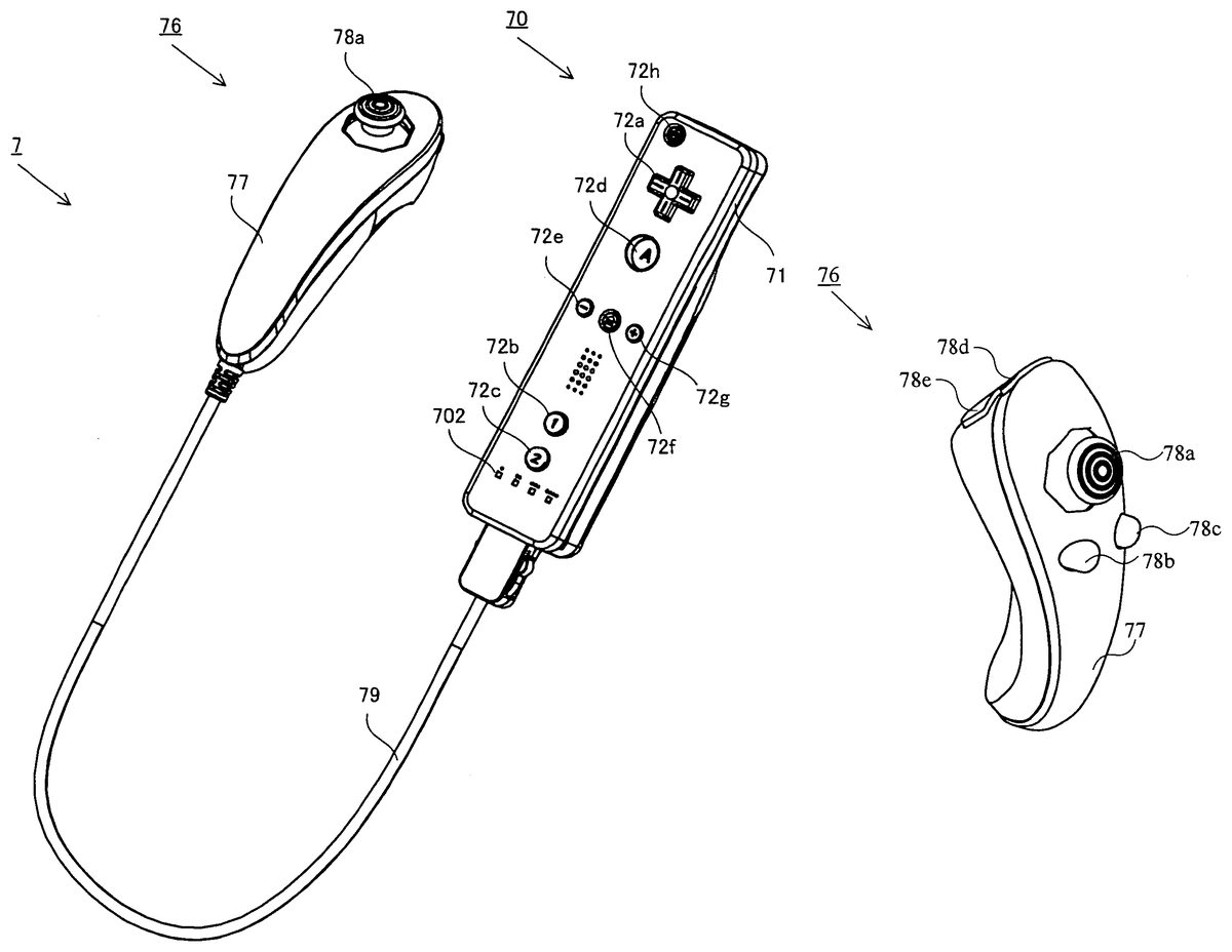
As shown inFIG. 3, the controller7includes the core unit70and the subunit76connected to each other by the connecting cable79. The core unit70has a housing71including a plurality of operation sections72. The subunit76has a housing77including a plurality of operation sections78. The core unit70and the subunit76are connected to each other by the connecting cable79.
As shown inFIG. 4, the connecting cable79has a connector791detachably connected to the connector73of the core unit70at one end thereof, and the connecting cable79is fixedly connected to the subunit76at the other end thereof. The connector791of the connecting cable79is engaged with the connector73provided at the rear surface of the core unit70so as to connect the core unit70and the subunit76to each other by the connecting cable79.
With reference toFIGS. 5 and 6, the core unit70will be described.FIG. 5is a perspective view of the core unit70as seen from the top rear side thereof.FIG. 6is a perspective view of the core unit70as seen from the bottom front side thereof.
As shown inFIGS. 5 and 6, the core unit70includes the housing71formed by plastic molding or the like. The housing71has a generally parallelepiped shape extending in a longitudinal direction from front to rear. The overall size of the housing71is small enough to be held by one hand of an adult or even a child.
At the center of a front part of a top surface of the housing71, a cross key72ais provided. The cross key72ais a cross-shaped four-direction push switch. The cross key72aincludes operation portions corresponding to the four directions (front, rear, right and left) represented by arrows, which are respectively located on cross-shaped projecting portions arranged at intervals of 90 degrees. The player selects one of the front, rear, right and left directions by pressing one of the operation portions of the cross key72a. Through an operation on the cross key72a, the player can, for example, instruct a direction in which a player character or the like appearing in a virtual game world is to move or a direction in which the cursor is to move.
Although the cross key72ais an operation section for outputting an operation signal in accordance with the aforementioned direction input operation performed by the player, such an operation section may be provided in another form. For example, the cross key72amay be replaced with a composite switch including a push switch including a ring-shaped four-direction operation section and a center switch provided at the center thereof. Alternatively, the cross key72amay be replaced with an operation section which includes an inclinable stick projecting from the top surface of the housing71and outputs an operation signal in accordance with the inclining direction of the stick. Still alternatively, the cross key72amay be replaced with an operation section which includes a disc-shaped member horizontally slidable and outputs an operation signal in accordance with the sliding direction of the disc-shaped member. Still alternatively, the cross key72amay be replaced with a touch pad. Still alternatively, the cross key72amay be replaced with an operation section which includes switches representing at least four directions (front, rear, right and left) and outputs an operation signal in accordance with the switch pressed by the player.
Behind the cross key72aon the top surface of the housing71, a plurality of operation buttons72b,72c,72d,72e,72fand72gare provided. The operation buttons72b,72c,72d,72e,72fand72gare each an operation section for outputting a respective operation signal assigned to the operation buttons72b,72c,72d,72e,72for72gwhen the player presses a head thereof. For example, the operation buttons72b,72c, and72dare assigned with functions of a first button, a second button, and an A button. Further, the operation buttons72e,72fand72gare assigned with functions of a minus button, a home button and a plus button, for example. The operation buttons72b,72c,72d,72e,72fand72gare assigned with respective functions in accordance with the game program executed by the game apparatus3, but this will not be described in detail because the functions are not directly relevant to the present invention. In an exemplary arrangement shown inFIG. 5, the operation buttons72b,72cand72dare arranged in a line at the center in the front-rear direction on the top surface of the housing71. The operation buttons72e,72fand72gare arranged in a line in the left-right direction between the operation buttons72band72don the top surface of the housing71. The operation button72fhas a top surface thereof buried in the top surface of the housing71, so as not to be inadvertently pressed by the player.
In front of the cross key72aon the top surface of the housing71, an operation button72his provided. The operation button72his a power switch for remote-controlling the power of the game apparatus3to be on or off. The operation button72halso has a top surface thereof buried in the top surface of the housing71, so as not to be inadvertently pressed by the player.
Behind the operation button72con the top surface of the housing71, a plurality of LEDs702are provided. The controller7is assigned a controller type (number) so as to be distinguishable from the other controllers7. For example, the LEDs702are used for informing the player of the controller type which is currently set to controller7that he or she is using. Specifically, when the core unit70transmits the transmission data to the receiving unit6, one of the plurality of LEDs702corresponding to the controller type is lit up.
On the top surface of the housing71, a sound hole for externally outputting a sound from a speaker706shown inFIG. 7, which will be described below, is provided between the operation buttons72e,72f, and72gand the operation button72b.
On a bottom surface of the housing71, a recessed portion is formed. As described later in detail, the recessed portion is formed at a position at which an index finger or middle finger of the player is located when the player holds the core unit70. On a rear slope surface of the recessed portion, an operation button72iis provided. The operation button72iis an operation section acting as, for example, a B button. The operation button72iis used, for example, as a trigger switch in a shooting game, or for attracting attention of a player object to a predetermined object.
On a front surface of the housing71, an image pickup element743included in the imaging information calculation section74is provided. The imaging information calculation section74is a system for analyzing image data taken by the core unit70and detecting for the centroid, the size and the like of an area having a high brightness in the image data. The imaging information calculation section74has, for example, a maximum sampling period of about 200 frames/sec., and therefore can trace and analyze even a relatively fast motion of the core unit70. The imaging information calculation section74will be described later in detail. On a rear surface of the housing71, the connector73is provided. The connector73is, for example, a 32-pin edge connector, and is used for engaging and connecting the core unit70with the connector791of the connecting cable79.
With reference toFIGS. 7 and 8, an internal structure of the core unit70will be described.FIG. 7is a perspective view illustrating, as seen from the rear side of the core unit70, a state where an upper casing (a part of the housing71) of the core unit70is removed.FIG. 8is a perspective view illustrating, as seen from the front side of the core unit70, a state where a lower casing (a part of the housing71) of the core unit70is removed.FIG. 8is a perspective view illustrating a reverse side of a substrate700shown inFIG. 7.
As shown inFIG. 7, the substrate700is fixed inside the housing71. On a top main surface of the substrate700, the operation buttons72a,72b,72c,72d,72e,72f,72gand72h, an acceleration sensor701, the LEDs702, an antenna754and the like are provided. These elements are connected to a micro computer751(seeFIGS. 8 and 17) and the like via lines (not shown) formed on the substrate700and the like. The wireless module753not shown (seeFIG. 17) and the antenna754allow the core unit70to act as a wireless controller. The quartz oscillator703not shown, which is provided in the housing71, generates a reference clock of the micro computer751described later. On the top main surface of the substrate700, the speaker706and an amplifier708are provided. The acceleration sensor701is provided near the edge of the substrate700offset from the center thereof. Therefore, a change of a direction of the gravitational acceleration and an acceleration containing a centrifugal force component can be detected based on a rotation of the core unit70about the longitudinal direction thereof, so that a predetermined calculation is used to determine the rotation of the core unit70with favorable accuracy based on the acceleration data having been detected.
As shown inFIG. 8, at a front edge of a bottom main surface of the substrate700, the imaging information calculation section74is provided. The imaging information calculation section74includes an infrared filter741, a lens742, the image pickup element743and an image processing circuit744located in this order from the front surface of the core unit70on the bottom main surface of the substrate700. At a rear edge of the bottom main surface of the substrate700, the connector73is attached. Further, a sound IC707and the micro computer751are provided on the bottom main surface of the substrate700. The sound IC707, which is connected to the micro computer751and the amplifier708via lines formed on the substrate700and the like, outputs a sound signal to the speaker706via the amplifier708based on the sound data transmitted from the game apparatus3. On the bottom main surface of the substrate700, a vibrator704is provided. The vibrator704is, for example, a vibration motor or a solenoid. The core unit70is vibrated by an actuation of the vibrator704, and the vibration is conveyed to the player's hand holding the core unit70. Thus, a so-called vibration-feedback game is realized. The vibrator704is disposed slightly toward the front of the housing71, thereby allowing the housing71held by the player to strongly vibrate, that is, allowing the player to easily feel the vibration.
With reference toFIGS. 9 to 12, the subunit76will be described.FIG. 9is a perspective view illustrating a first example of the subunit76.FIG. 10is a perspective view illustrating a state where an upper casing (a part of the housing77) of the subunit76shown inFIG. 9is removed.FIG. 11Ais a top view illustrating a second example of the subunit76.FIG. 11Bis a bottom view illustrating the second example of the subunit76.FIG. 11Cis a left side view illustrating the second example of the subunit76.FIG. 12is a perspective view illustrating the second example of the subunit76as seen from the top front side thereof.
As shown inFIG. 9, the subunit76includes the housing77formed by, for example, plastic molding. The housing77extends in a longitudinal direction from front to rear, and has a streamline solid shape including a head which is a widest portion in the subunit76. The overall size of the subunit76is small enough to be held by one hand of an adult or even a child.
In the vicinity of the widest portion on the top surface of the housing77, a stick78ais provided. The stick78ais an operation section which includes an inclinable stick projecting from the top surface of the housing77and outputs an operation signal in accordance with the inclining direction of the stick. For example, a player can arbitrarily designate a direction and a position by inclining a tip of the stick in any direction of 360 degrees, whereby the player can instruct a direction in which a player character or the like appearing in a virtual game world is to move, or can instruct a direction in which a cursor is to move.
In front of the housing77of the subunit76, a plurality of operation buttons78dand78eare provided. The operation buttons78dand78eare each an operation section for outputting a respective operation signal assigned to the operation buttons78dand78ewhen the player presses a head thereof. For example, the operation buttons78dand78eare assigned with functions of an X button and a Y button, for example. Although the operation buttons78dand78eare assigned with respective functions in accordance with the game program executed by the game apparatus3, this will not be described in detail because the functions are not directly relevant to the present invention. In an exemplary arrangement shown inFIG. 9, the operation buttons78dand78eare aligned from the top to bottom on the front surface of the housing77.
InFIG. 10, a substrate is fixed in the housing77. The stick78a, an acceleration sensor761and the like are provided on the top main surface of the substrate. The stick78a, the acceleration sensor761and the like are connected to the connecting cable79via lines (not shown) formed on the substrate and the like.
As shown inFIGS. 11A,11B,11C and12, the subunit76of the second example includes the housing77, the stick78a, the operation buttons78dand78eas in the case of the subunit76of the first example, and the subunit76of the second example has the operation buttons78band78con the top surface of the housing77.
Behind the stick78aon the top surface of the housing77, the subunit76of the second example has a plurality of operation buttons78band78c. The operation buttons78band78care each an operation section for outputting a respective operation signal assigned to the operation buttons78band78cwhen the player presses a head thereof. The operation buttons78band78care assigned with respective functions in accordance with the game program executed by the game apparatus3. However, this will not be described in detail because the functions are not directly relevant to the present invention. In an exemplary arrangement shown inFIGS. 11A,11B, and11C and12, the operation buttons78band78care arranged in a line at the center of the top surface of the housing77in the left-right direction.
Although the stick78ais an operation section for outputting an operation signal in accordance with a direction input operation performed by the player as described above, such an operation section may be provided in another form. Hereinafter, with reference toFIGS. 13 to 16, a first through a fifth exemplary modifications, each of which includes the subunit76of the second example having an operation section for outputting an operation signal in accordance with the direction input operation, will be described.
As the first exemplary modification, as shown inFIG. 13, the subunit76may include a cross key78fsimilar to the cross key72aof the core unit70instead of the stick78a. As the second exemplary modification, as shown inFIG. 14, the subunit76may include a slide pad78gwhich includes a disc-shaped member horizontally slidable and outputs an operation signal in accordance with the sliding direction of the disc-shaped member, instead of the stick78a. As the third exemplary modification, as shown inFIG. 15, the subunit76may include a touch pad78hinstead of the stick78a. As the fourth exemplary modification, as shown inFIG. 16, the subunit76may include an operation section which has buttons78i,78j,78k, and78lrepresenting at least four directions (front, rear, right and left), respectively, and outputs an operation signal in accordance with the button (78i,78j,78k, or78l) pressed by a player, instead of the stick78a. As the fifth exemplary modification, the subunit76may include a composite switch including a push switch having a ring-shaped four-direction operation section and a center switch provided at the center thereof, instead of the stick78a.
Next, with reference toFIG. 17, an internal structure of the controller7will be described.FIG. 17is a block diagram illustrating the structure of the controller7.
As shown inFIG. 17, the core unit70includes the communication section75in addition to the operation section72, the imaging information calculation section74, the acceleration sensor701, the speaker706, the sound IC707, and the amplifier708as described above. Further, the subunit76, which has the operation section78and the acceleration sensor761as described above, is connected to the micro computer751via the connecting cable79and the connectors791and73.
The imaging information calculation section74includes the infrared filter741, the lens742, the image pickup element743and the image processing circuit744. The infrared filter741allows only infrared light to pass therethrough, among light incident on the front surface of the core unit70. The lens742collects the infrared light which has passed through the infrared filter741and outputs the infrared light to the image pickup element743. The image pickup element743is a solid-state imaging device such as, for example, a CMOS sensor or a CCD. The image pickup element743takes an image of the infrared light collected by the lens742. Accordingly, the image pickup element743takes an image of only the infrared light which has passed through the infrared filter741and generates image data. The image data generated by the image pickup element743is processed by the image processing circuit744. Specifically, the image processing circuit744processes the image data obtained from the image pickup element743, identifies a spot thereof having a high brightness, and outputs process result data representing the identified position coordinates and size of the area to the communication section75. The imaging information calculation section74is fixed to the housing71of the core unit70. The imaging direction of the imaging information calculation section74can be changed by changing the direction of the housing71. The housing71is connected to the subunit76by the flexible connecting cable79, and therefore the imaging direction of the imaging information calculation section74is not changed by changing the direction and position of the subunit76. As described later in detail, a signal can be obtained in accordance with the position and the motion of the core unit70based on the process result data outputted by the imaging information calculation section74.
The core unit70preferably includes a three-axis acceleration sensor701. Further, the subunit76preferably includes a three-axis acceleration sensor761. The three axis acceleration sensors701and761each detects for a linear acceleration in three directions, i.e., the up/down direction, the left/right direction, and the forward/backward direction. Alternatively, a two axis acceleration detection means which detects for only a linear acceleration along each of the up/down and left/right directions (or other pair of directions) may be used in another embodiment depending on the type of control signals used in the game process. For example, the three axis acceleration sensors701and761or the two axis acceleration sensors701and761may be of the type available from Analog Devices, Inc. or STMicroelectronics N.V. Preferably, each of the acceleration sensors701and761is of an electrostatic capacitance (capacitance-coupling) type that is based on silicon micro-machined MEMS (Micro Electro Mechanical Systems) technology. However, any other suitable acceleration detection technology (e.g., piezoelectric type or piezoresistance type) now existing or later developed may be used to provide the three axis acceleration sensors701and761or two axis acceleration sensors701and761.
As one skilled in the art understands, the acceleration detection means, as used in the acceleration sensors701and761, are capable of detecting for only acceleration (linear acceleration) along a straight line corresponding to each axis of the acceleration sensor. In other words, each of the direct outputs of the acceleration sensors701and761is limited to signals indicative of linear acceleration (static or dynamic) along each of the two or three axes thereof. As a result, the acceleration sensors701and761cannot directly detect movement along a non-linear (e.g. arcuate) path, rotation, rotational movement, angular displacement, tilt, position, attitude or any other physical characteristic.
However, through additional processing of the acceleration signals output from each of the acceleration sensors701and761, additional information relating to the core unit70and the subunit76can be inferred or calculated, as one skilled in the art will readily understand from the description herein. For example, by detecting static acceleration (i.e., gravity), the outputs of the acceleration sensors701and761can be used to infer tilt of the object (core unit70or subunit76) relative to the gravity vector by correlating tilt angles with detected acceleration. In this way, the acceleration sensors701and761can be used in combination with the micro computer751(or another processor) to determine tilts, attitudes or positions of the core unit70and the subunit76. Similarly, various movements and/or positions of the core unit70and the subunit76can be calculated or inferred through processing of the acceleration signals generated by the acceleration sensors701and761when the core unit70containing the acceleration sensor701or the subunit76containing the acceleration sensor761is subjected to dynamic accelerations by, for example, the hand of a user, as described herein. In another embodiment, each of the acceleration sensors701and761may include an embedded signal processor or other type of dedicated processor for performing any desired processing of the acceleration signals outputted from the acceleration detection means prior to outputting signals to micro computer751. For example, the embedded or dedicated processor could convert the detected acceleration signal to a corresponding tilt angle when the acceleration sensor is intended to detect static acceleration (i.e., gravity). Data representing the acceleration detected by each of the acceleration sensors701and761is outputted to the communication section75.
In another exemplary embodiment, at least one of the acceleration sensors701and761may be replaced with a gyro-sensor of any suitable technology incorporating, for example, a rotating or vibrating element. Exemplary MEMS gyro-sensors that may be used in this embodiment are available from Analog Devices, Inc. Unlike the acceleration sensors701and761, a gyro-sensor is capable of directly detecting rotation (or angular rate) around at least one axis defined by the gyroscopic element therein. Thus, due to the fundamental differences between a gyro-sensor and an acceleration sensor, corresponding changes need to be made to the processing operations that are performed on the output signals from these devices depending on which device is selected for a particular application.
More specifically, when the tilt or attitude is calculated using a gyro-sensor instead of the acceleration sensor, significant changes are necessary. Specifically, when using a gyro-sensor, the value of the tilt is initialized at the start of the detection. Then, data on the angular rate which is output from the gyro-sensor is integrated. Next, a change amount in tilt from the value, of the tilt initialized is calculated. In this case, the calculated tilt corresponds to an angle. In contrast, when the acceleration sensor calculates the tilt, the tilt is calculated by comparing the value of the gravitational acceleration of each axial component with a predetermined reference. Therefore, the calculated tilt can be represented as a vector. Thus, without initialization, an absolute direction can be determined with an acceleration detection means. The type of the value calculated as the tilt is also very different between a gyro sensor and an acceleration sensor; i.e., the value is an angle when a gyro sensor is used and is a vector when an acceleration sensor is used. Therefore, when a gyro sensor is used instead of an acceleration sensor or vice versa, data on tilt also needs to be processed through a predetermined conversion taking into account the fundamental differences between these two devices. Due to the fact that the nature of gyroscopes is known to one skilled in the art, as well as the fundamental differences between the acceleration detection means and the gyroscope, further details are not provided herein. While a gyro-sensor is advantageous in that a rotation can be directly detected, an acceleration sensor is generally more cost effective when used in connection with the controller described herein.
The communication section75includes the microcomputer751, a memory752, the wireless module753and the antenna754. The micro computer751controls the wireless module753for wirelessly transmitting the transmission data while using the memory752as a storage area during the process. Further, the micro computer751controls the sound IC707and the vibrator704based on data from the game apparatus3having been received by the wireless module753via the antenna754. The sound IC707processes sound data transmitted from the game apparatus3via the communication section75, and the like.
Data from the core unit70including an operation signal (core key data) from the operation section72, acceleration signals (core acceleration data) from the acceleration sensor701, and the process result data from the imaging information calculation section74are outputted to the micro computer751. An operation signal (sub key data) from the operation section78of the subunit76and acceleration signals (sub acceleration data) from the acceleration sensor761are outputted to the micro computer751via the connecting cable79. The micro computer751temporarily stores the input data (core key data, sub key data, core acceleration data, sub acceleration data, and process result data) in the memory752as the transmission data which is to be transmitted to the receiving unit6. The wireless transmission from the communication section75to the receiving unit6is performed periodically at a predetermined time interval. Since game process is generally performed at a cycle of 1/60 sec., data needs to be collected and transmitted at a cycle of a shorter time period. Specifically, the game process unit is 16.7 ms ( 1/60 sec.), and the transmission interval of the communication section75structured using the Bluetooth (registered trademark) technology is 5 ms. At the transmission timing to the receiving unit6, the micro computer751outputs the transmission data stored in the memory752as a series of operation information to the wireless module753. The wireless module753uses, for example, the Bluetooth (registered trademark) technology to modulate the operation information onto a carrier wave of a predetermined frequency, and radiates the low power radio wave signal from the antenna754. Thus, the core key data from the operation section72included in the core unit70, the sub key data from the operation section78included in the subunit76, the core acceleration data from the acceleration sensor701included in the core unit70, the sub acceleration data from the acceleration sensor761included in the subunit76, and the process result data from the imaging information calculation section74are modulated onto the low power radio wave signal by the wireless module753and radiated from the core unit70. The receiving unit6of the game apparatus3receives the low power radio wave signal, and the game apparatus3demodulates or decodes the low power radio wave signal to obtain the series of operation information (the core key data, the sub key data, the core acceleration data, the sub acceleration data and the process result data). Based on the obtained operation information and the game program, the CPU30of the game apparatus3performs the game process. In the case where the communication section75is structured using the Bluetooth (registered trademark) technology, the communication section75can have a function of receiving transmission data which is wirelessly transmitted from other devices.
As shown inFIG. 18, in order to play a game using the controller7with the game system1, a player holds the core unit70with one hand (for example, a right hand) (seeFIGS. 19 and 20), and holds the subunit76with the other hand (for example, a left hand) (seeFIG. 22). The player holds the core unit70so as to point the front surface of the core unit70(that is, a side having an entrance through which light is incident on the imaging information calculation section74taking an image of the light) to the monitor2. On the other hand, two LED modules8L and8R are provided in the vicinity of the display screen of the monitor2. The LED modules8L and8R each outputs infrared light forward from the monitor2.
When a player holds the core unit70so as to point the front surface thereof to the monitor2, infrared lights outputted by the two LED modules8L and8R are incident on the imaging information calculation section74. The image pickup element743takes images of the infrared lights incident through the infrared filter741and the lens742, and the image processing circuit744processes the taken images. The imaging information calculation section74detects infrared components outputted by the LED modules8L and8R so as to obtain positions and area information of the LED modules8L and8R. Specifically, the imaging information calculation section74analyzes image data taken by the image pickup element743, eliminates images which do not represent the infrared lights outputted by the LED modules8L and8R from the area information, and identifies points each having a high brightness as positions of the LED modules8L and8R. The imaging information calculation section74obtains position coordinates, coordinates of the centroid, and the like of each of the identified points having the high brightness and outputs the same as the process result data. When such process result data is transmitted to the game apparatus3, the game apparatus3can obtain, based on the position coordinates and the coordinates of the centroid, operation signals relating to the motion, attitude, position and the like of the imaging information calculation section74, that is, the core unit70, with respect to the LED modules8L and8R. Specifically, the position having a high brightness in the image obtained through the communication section75is changed in accordance with the motion of the core unit70, and therefore a direction input or coordinate input is performed in accordance with the position having the high brightness being changed, thereby enabling a direction input or a coordinate input to be performed along the moving direction of the core unit70.
Thus, the imaging information calculation section74of the core unit70takes images of stationary markers (infrared lights from the two LED modules8L and8R in the present embodiment), and therefore the game apparatus3can use the process result data relating to the motion, attitude, position and the like of the core unit70in the game process, whereby an operation input, which is different from an input made by pressing an operation button or using an operation key, is further intuitively performed. As described above, since the markers are provided in the vicinity of the display screen of the monitor2, the motion, attitude, position and the like of the core unit70with respect to the display screen of the monitor2can be easily calculated based on positions from the markers. That is, the process result data used for obtaining the motion, attitude, position and the like of the core unit70can be used as operation input immediately applied to the display screen of the monitor2.
With reference toFIGS. 19 and 20, a state of a player holding the core unit70with one hand will be described.FIG. 19shows an exemplary state of a player holding the core unit70with a right hand as seen from the front surface side of the core unit70.FIG. 20shows an exemplary state of a player holding the core unit70with a right hand as seen from the left side of the core unit70.
As shown inFIGS. 19 and 20, the overall size of the core unit70is small enough to be held by one hand of an adult or even a child. When the player puts a thumb on the top surface of the core unit70(for example, near the cross key72a), and puts an index finger in the recessed portion on the bottom surface of the core unit70(for example, near the operation button72i), the light entrance of the imaging information calculation section74on the front surface of the core unit70is exposed forward to the player. It should be understood that also when the player holds the core unit70with a left hand, the holding state is the same as that described for the right hand.
Thus, the core unit70allows a player to easily operate the operation section72such as the cross key72aor the operation button72iwhile holding the core unit70with one hand. Further, when the player holds the core unit70with one hand, the light entrance of the imaging information calculation section74on the front surface of the core unit70is exposed, whereby the light entrance can easily receive infrared lights from the aforementioned two LED modules8L and8R. That is, the player can hold the core unit70with one hand without preventing the imaging information calculation section74from functioning. That is, when the player moves his or her hand holding the core unit70with respect to the display screen, the core unit70can further perform an operation input enabling a motion of the player's hand to directly act on the display screen.
As shown inFIG. 21, the LED modules8L and8R each has a viewing angle θ1. The image pickup element743has a viewing angle θ2. For example, the viewing angle θ1of the LED modules8L and8R is 34 degrees (half-value angle), and the viewing angle θ2of the image pickup element743is 41 degrees. When both the LED modules8L and8R are in the viewing angle θ2of the image pickup element743, and the image pickup element743is in the viewing angle θ1of the LED module8L and the viewing angle θ1of the LED module8R, the game apparatus3determines a position of the core unit70using positional information relating to the point having high brightness of the two LED modules8L and8R.
When either the LED module8L or LED module8R is in the viewing angle θ2of the image pickup element743, or when the image pickup element743is in either the viewing angle θ1of the LED module8L or the viewing angle θ1of the LED module8R, the game apparatus3determines a position of the core unit70using the positional information relating to the point having high brightness of the LED module8L or the LED module8R.
As described above, the tilt, attitude or position of the core unit70can be determined based on the output (core acceleration data) from the acceleration sensor701of the core unit70. That is, the core unit70functions as an operation input means for performing an operation in accordance with a player moving a hand holding the core unit70, for example, upward, downward, leftward, or rightward.
Next, with reference toFIG. 22, a state of a player holding the subunit76with one hand will be described.FIG. 22shows an exemplary state of a player holding the subunit76with a left hand as seen from the right side of the subunit76.
As shown inFIG. 22, the overall size of the subunit76is small enough to be held by one hand of an adult or even a child. For example, a player can put a thumb on the top surface of the subunit76(for example, near the stick78a), put an index finger on the front surface of the subunit76(for example, near the operation buttons78dand78e), and put a middle finger, a ring finger and a little finger on the bottom surface of the subunit76so as to hold the subunit76. It should be understood that also when the player holds the subunit76with a right hand, the holding state is similar to that described for the left hand. Thus, the subunit76allows the player to easily operate the operation section78such as the stick78aand the operation buttons78dand78ewhile holding the subunit76with one hand.
As described above, the tilt, attitude or position of the subunit76can be determined based on the output (sub acceleration data) from the acceleration sensor761of the subunit76. That is, the subunit76functions as an operation input means for performing an operation in accordance with the player moving a hand holding the subunit76, for example, upward, downward, leftward, and rightward.
Here, an exemplary game played using the aforementioned controller7will be described. As a first example, a shooting game played using the controller7will be described.FIG. 23is a diagram illustrating an exemplary game image displayed on the monitor2when the game apparatus3executes the shooting game.
As shown inFIG. 23, a portion of a three-dimensional virtual game space S is displayed on the display screen of the monitor2. As a game object acting in accordance with an operation of the controller7, a portion of the player character P and a portion of a gun G held by the player character P are displayed on the display screen. Moreover, the virtual game spaces displayed on the display screen represents a field of front vision of the player character P, and for example an opponent character E is displayed as a shooting target inFIG. 23. A target indicating a position at which the player character P shoots the gun G is displayed on the display screen as the target cursor T.
In the shooting game having such a game image displayed on the monitor2, a player operates the core unit70with one hand and operates the subunit76with the other hand as shown inFIG. 18so as to play the game. For example, when the player inclines the stick78a(seeFIGS. 11A,11B,11C and12) on the subunit76, the player character P is moved in the virtual game space S in accordance with the inclining direction. Further, when the player moves his or her hand holding the core unit70with respect to the display screen, the target cursor T is moved in accordance with the motion, attitude, position and the like of the core unit70with respect to the monitor2(LED modules8L and8R). When the player presses the operation button72i(shown inFIG. 6) on the core unit70, the player character P shoots the gun G at the target cursor T.
That is, while the player uses the stick78aon the subunit76so as to instruct the player character P to move, the player can operate the core unit70as if the core unit70is a gun for the shooting game, thereby enhancing enjoyment in playing a shooting game. The player can perform an operation of moving the player character P and an operation of moving the target cursor T by using respective units held by different hands, whereby the player can perform the respective operations as independent ones. For example, since the virtual game space S displayed on the display screen is changed in accordance with the movement of the player character P, it is sometimes difficult to keep the target positioned near a position observed by the player in the virtual game space S because, for example, the player may be paying attention to the opponent character E suddenly jumping into the virtual game space S. However, while the player is moving the player character P with one hand (for example, a thumb of a left hand), the player can control a motion of the arm (for example, a right arm) which is not used for moving the player character P such that the core unit70has its front surface pointed to the observed position, thereby substantially enhancing flexibility for operating the controller7and increasing the reality of the shooting game. Further, in order to move the target cursor T, the player moves the controller. However, the operation of moving the controller does not hinder the player from performing a direction instruction operation for moving the player character P, thereby enabling the player to stably perform the two direction instruction operations. That is, by using the controller7, the player can freely use his or her left and right hands and can perform a new operation having increased flexibility, which cannot be achieved using a physically single controller.
In a second example, a player inclines the stick78aon the subunit76so as to move the player character P in the virtual game space S in accordance with the inclining direction as in the first example. The player moves a hand holding the core unit70with respect to the display screen so as to move a sight point of a virtual camera in accordance with a position of the core unit70with respect to the monitor2(LED modules8L and8R). These operations allow the player to observe a position to which the core unit70is pointed in the virtual game space S while operating the stick78aon the subunit76so as to instruct the player character P to move.
In the above description, the controller7and the game apparatus3are connected to each other by wireless communication. However, the controller7and the game apparatus3may be electrically connected to each other by a cable. In this case, the cable connected to the core unit70is connected to a connection terminal of the game apparatus3.
Moreover, in the present embodiment, only the core unit70among the core unit70and the subunit76of the controller7has the communication section75. However, the subunit76may have the communication section for wirelessly transmitting the transmission data to the receiving unit6. Further, both the core unit70and the subunit76may have the respective communication sections. For example, the respective communication sections included in the core unit70and the subunit76may wirelessly transmit the transmission data to the receiving unit6, or the communication section of the subunit76may wirelessly transmit the transmission data to the communication section75of the core unit70, and the communication section75of the core unit70may wirelessly transmit, to the receiving unit6, the received transmission data from the subunit76and the transmission data of the core unit70. In these cases, the connecting cable79for electrically connecting between the core unit70and the subunit76can be eliminated.
In the above description, the receiving unit6connected to the connection terminal of the game apparatus3is used as a receiving means for receiving transmission data which is wirelessly transmitted from the controller7. Alternatively, the receiving means may be a receiving module built in the game apparatus3. In this case, the transmission data received by the receiving module is outputted to the CPU30via a predetermined bus.
Although in the present embodiment the imaging information calculation section74included in the core unit70is described as an example of a determining section for outputting a signal (process result data) in accordance with a motion of the core unit70body, the imaging information calculation section74may be provided in another form. For example, the core unit70may include the acceleration sensor701as described above, or may include a gyro sensor. The acceleration sensor or the gyro sensor can be used to determine a motion or attitude of the core unit70, and, therefore, can be used as a determining section for outputting a signal in accordance with the motion of the core unit70body using the detection signal for the motion or attitude. In this case, the imaging information calculation section74may be eliminated from the core unit70, or sensor and the imaging information calculation section can be used in combination.
Further, although in the present embodiment only the core unit70includes the imaging information calculation section74, the subunit76may also include a similar imaging information calculation section.
Further, when the controller7includes a plurality of units, each of which may have a plurality of operation means such as the imaging information calculation section, the acceleration sensor, the gyro sensor, the stick, the cross key, and the operation button, various combination of the operation means can realize various controllers. Here, the operation means included in the core unit70and the subunit76are classified into an operation means A and an operation means B. The operation means A, such as the imaging information calculation section74, the acceleration sensors701and761, and the gyro sensor, outputs a signal in accordance with the movement of the unit body. The operation means B, such as the stick, the cross key, the operation button, the touch pad, outputs a signal in accordance with the player pressing a button, tilting a component or touching the same.
When the core unit70includes the operation means A and the subunit76includes the operation means B, the player can move one hand holding the core unit70while the player makes an input with a finger of the other hand holding the subunit76as in the case of a conventional controller. That is, the player can perform different operations with a right and a left hands, respectively, thereby realizing a new operation which cannot be performed by a conventional controller. In this case, according to the present invention, operation data outputted by the operation means A corresponds to first operation data, and operation data outputted by the operation means B corresponds to second operation data. Further, the controller may be constructed such that the subunit76may include the operation means A, the core unit70may include the operation means A, and the subunit76may include the operation means A and the operation means B. In this manner, the player can move both hands individually, thereby realizing an increasingly improved operation. In this case, according to the present invention, operation data outputted by the operation means A of the subunit76corresponds to third operation data.
Further, when the core unit70and the subunit76each includes the operation means A, the player can move one hand holding the core unit70while the player can move the other hand holding the subunit76so as to make an input. That is, the player can move a right and a left hands individually, thereby realizing a new operation which cannot be performed by a conventional controller. In this case, according to the present invention, operation data outputted by the respective operation means A of the core unit70and the subunit76correspond to first operation data and second operation data. Further, each of the core unit70and the subunit76may include both the operation means A and the operation means B. In this manner, the player can perform operations by moving both hands and using fingers of both hands, thereby realizing a new operation. In this case, according to the present invention, operation data outputted by the operation means B of the core unit70corresponds to first key operation data, and operation data outputted by the operation means B of the subunit76corresponds to second key operation data.
Furthermore, when each of the core unit70and the subunit76includes the operation means A, one of the core unit70or the subunit76may include various types of operation means A. As described above, when the operation means A includes the imaging information calculation section, a direction, a position and the like of the unit with respect to the imaging target (marker) can be calculated, thereby enabling an operation based on the direction and the position of the unit with respect to the monitor2. On the other hand, when the operation means A includes the acceleration sensor or the gyro sensor, a tilt, an attitude, a position and the like of the unit itself can be calculated, thereby enabling an operation based on the attitude and the position of the unit. Accordingly, when the core unit70includes the imaging information calculation section and one of the acceleration sensor or the gyro sensor, and the subunit76includes the acceleration sensor or the gyro sensor, the core unit70can perform the aforementioned two operations. In this case, according to the present invention, operation data outputted by the imaging information calculation section of the core unit70corresponds to first operation data, operation data outputted by the acceleration sensor or the gyro sensor of the subunit76corresponds to second operation data, and operation data outputted by the acceleration sensor or the gyro sensor of the core unit70corresponds to third operation data.
In the present embodiment, image data taken by the image pickup element743is analyzed so as to obtain position coordinates and the like of an image of infrared lights from the LED modules8L and8R, and the core unit70generates process result data from the obtained coordinates and the like and transmits the process result data to the game apparatus3. However, the core unit70may transmit data obtained in another process step to the game apparatus3. For example, the core unit70transmits to the game apparatus3image data taken by the image pickup element743, and the CPU30may perform the aforementioned analysis so as to obtain process result data. In this case, the image processing circuit744can be eliminated from the core unit70. Alternatively, the core unit70may transmit, to the game apparatus3, the image data having been analyzed halfway. For example, the core unit70transmits to the game apparatus3data indicating a brightness, a position, an area size and the like obtained from the image data, and the CPU30may perform the remaining analysis so as to obtain process result data.
Although in the present embodiment infrared lights from the two LED modules8L and8R are used as imaging targets of the imaging information calculation section74in the core unit70, the imaging target is not restricted thereto. For example, infrared light from one LED module or infrared lights from at least three LED modules provided in the vicinity of the monitor2may be used as the imaging target of the imaging information calculation section74. Alternatively, the display screen of the monitor2or another emitter (room light or the like) can be used as the imaging target of the imaging information calculation section74. When the position of the core unit70with respect to the display screen is calculated based on the positional relationship between the imaging target and the display screen of the monitor2, various emitters can be used as the imaging target of the imaging information calculation section74.
The aforementioned shapes of the core unit70and the subunit76are merely examples. Further, the shape, the number, setting position and the like of each of the operation section72of the core unit70and the operation section78of the subunit76are merely examples. Needless to say, even when the shape, the number, the setting position and the like of each of the core unit70, the subunit76, the operation section72, and the operation section78are different from those described in the embodiment, the present invention can be realized. Further, the imaging information calculation section74(light entrance of the imaging information calculation section74) of the core unit70may not be positioned on the front surface of the housing71. The imaging information calculation section74may be provided on another surface at which light can be received from the exterior of the housing71.
Further, although the speaker706, the sound IC707, and the amplifier708as described above are included in the core unit70, any devices at hand capable of outputting a sound may be included in either the subunit76or the core unit70.
Thus, the controller of the present invention allows a player to operate both the core unit70and the subunit76included therein so as to enjoy a game. For example, the core unit70has a function of outputting a signal in accordance with a motion of the unit body including the imaging information calculation section74and the accelerator sensor701, and the subunit76has a function of outputting a signal in accordance with a direction input operation performed by the player. For example, when used is a controller into which the core unit70and the subunit76are integrated, the whole controller has to be moved so as to output a signal in accordance with the motion of the unit body, thereby exerting some influence on the direction input operation. Further, the integration of the core unit70and the subunit76causes the opposite influence, that is, flexibility, which is realized by separation between the core unit70and the subunit76, is substantially reduced. As another example, the core unit70may have a function of outputting a signal in accordance with a motion of the unit body including the imaging information calculation section74and the acceleration sensor701, and the subunit76may have a function of outputting a signal in accordance with the motion of the unit body including the acceleration sensor761. Therefore, the player can move both hands holding the different units individually so as to make an input. Accordingly, the core unit70and the subunit76can be separated into a right unit and a left unit as in the case of a conventional controller for the game apparatus, and simultaneously the core unit70and the subunit76allow the player to freely use his or her right and left hands, thereby providing the player with a new operation, which cannot be performed by the integrated controller. Further, the controller can be operated with substantially enhanced flexibility, thereby providing a player with a game operation having increased reality.
The game controller and the game system according to the present invention can realize an operation having increased flexibility, and are useful as a game controller which includes two independent units and is operated by a player holding the two independent units, a game system including the game controller, and the like.
While the invention has been described in detail, the foregoing description is in all aspects illustrative and not restrictive. It is understood that numerous other modifications and variations can be devised without departing from the scope of the invention.
Claims
- An ergonomic controller configured to be grasped by a hand of a user, the controller comprising: a symmetrical housing having an elongated shape comprising: a convex curved surface structurally dimensioned and shaped to contact a palm of a partially closed hand grasping and supporting the housing, a complex curved surface that is simultaneously convex in one dimension and concave in another dimension to define a saddle surface, the complex curved surface dimensioned, curved, and configured to trap and be supported by at least a middle finger of the grasping hand contacting the saddle surface, and a forward surface disposed between the convex curved surface and the complex curved surface, the forward surface being dimensioned and shaped to be reachable by an index finger of the grasping hand;an operation section positioned on the forward surface to be operated by at least the index finger of the grasping hand;and an output device disposed within the housing and operatively connected to the operation section, the output device outputting signals responsive at least to operation of the operation section.
- The controller of claim 1 , wherein the operation section includes at least a first operation button on the forward surface configured to output operation data based on operation of the first operation button.
- The controller of claim 1 , further comprising an operation control provided on the convex curved surface of the housing.
- The controller of claim 1 , further comprising a direction input section comprising a stick projecting from the convex curved surface, direction being designated by inclining the stick.
- The controller of claim 4 , wherein an octagonal opening for allowing the stick to project from the convex curved surface is formed on the convex curved surface of the housing.
- The controller of claim 4 , wherein the direction input section includes four independent operation buttons provided in a forward direction, a backward direction, a rightward direction, and a leftward direction.
- The controller of claim 1 , further comprising a direction input section comprising a cross-shaped switch.
- The controller of claim 1 , further comprising a direction input section comprising at least one of a slide pad and a touch pad, the at least one of the slide pad and the touch pad configured to designate a direction.
- The controller of claim 1 , further comprising an inertial sensor disposed in the housing to sense and output data based on aspects of orientation.
- The controller of claim 9 , wherein the inertial sensor is at least one of an accelerometer and/or a gyro sensor.
- The controller of claim 1 , wherein the output device comprising: a transceiver configured to send/receive data;a speaker;and a sound controller configured to generate sound.
- The controller of claim 1 , wherein the complex curved surface comprises a latitudinal convex curvature and a longitudinal concave curvature.
- The controller of claim 1 , wherein the forward surface and the convex surface meet at an edge.
- The controller of claim 1 , wherein the complex curved surface further conformed to engage a ring finger and a little finger of the grasping hand.
- The controller of claim 1 , wherein the forward surface intersects a curve defined by the convex surface such that the index finger of the grasping hand can move directly from the forward surface to the convex surface without removing the index finger from the housing of the controller.
- A controller, comprising: an elongated housing including a head portion and a body portion adjacent to the head portion, the housing further including a top curved surface having a convex curvature, a bottom curved surface opposed to the top curved surface and having a convex curvature and a concave curvature, and a front curved surface substantially perpendicular to the top and bottom surfaces in the head portion of the housing and having a convex curvature;a first operation button section provided on the front curved surface of the housing, the first operation button section outputs, as operation data, data based on an operation performed through the first operation button section;and an output device disposed within the housing and operatively connected to the first operation button section, the output device outputting signals responsive at least to operation of the first operation button section, the concave curvature and the convex curvature of the bottom curved surface sharing a saddle point of the bottom curved surface and being bisected by a plane of symmetry, and the front curved surface meeting the bottom curved surface at a first edge and the front curved surface meeting the top curved surface at a second edge oppositely located to the first edge.
- The controller of claim 16 , further comprising: a direction input section provided at the head portion of the top curved surface of the housing and configured to allow the user to designate a direction, the direction input section outputs, as the operation data, data based on the direction designated by the user.
- The controller according to claim 17 , wherein the direction input section is a stick which projects from the top curved surface of the housing, the direction input section configured to designate a direction by inclining the stick.
- The controller according to claim 18 , wherein an octagonal opening for allowing the stick to project from the top curved surface of the housing is formed on the top curved surface of the housing.
- The controller according to claim 17 , wherein the direction input section includes four independent operation buttons provided in a forward direction, a backward direction, and a rightward direction, and a leftward direction, respectively.
- The controller according to claim 17 , wherein the direction input section is a cross-shaped switch.
- The controller according to claim 17 , wherein the direction input section is one of a slide pad and a touch pad, the one of the slide pad and the touch pad being capable of allowing a direction to be designated.
- The controller according to claim 16 , further comprising one of an acceleration sensor and a gyro sensor, the one of the acceleration sensor and the gyro sensor being incorporated in the housing so as to output data based on a motion of the housing, wherein the operation data further includes output data from one of the acceleration sensor and the gyro sensor.
- The controller according to claim 16 , further comprising: a transceiver configured to send/receive data;a speaker;and a sound controller configured to generate sound from the speaker.
- The controller according to claim 16 , wherein the convex curvature being a latitudinal convex curvature and the concave curvature being a longitudinal concave curvature.
- The controller according to claim 16 , wherein the concave curvature of the bottom curved surface being in the head portion of the elongated housing and the convex curvature of the bottom curved surface being in the body portion of the elongated housing.
- The controller according to claim 16 , wherein the second edge of the front curved surface intersecting a curve defined by the top curved surface.
- A controller arrangement, comprising: a core unit, comprising: a housing having a parallelepiped shape extending in a longitudinal direction, the housing having a top surface and a bottom surface, and an operation section having at least a direction input section provided at a front part of the top surface of the housing, for allowing a user to designate a direction and outputs, as the operation data, at least data based on the direction designated through the direction input section;and a sub unit operatively coupled to the core unit, the sub unit comprising: an elongated housing including a head portion and a body portion adjacent to the head portion, the housing further including a top curved surface having a convex curvature, a bottom curved surface opposed to the top curved surface and having a convex curvature and a concave curvature, and a front curved surface substantially perpendicular to the top and bottom surfaces in the head portion of the housing and having a convex curvature;a first operation button section provided on the front curved surface of the housing, the first operation button section outputs, as operation data, data based on an operation performed through the first operation button section;and an output device disposed within the housing and operatively connected to the first operation button section, the output device outputting signals responsive at least to operation of the first operation button section, the concave curvature and the convex curvature of the bottom curved surface sharing a saddle point of the bottom curved surface and being bisected by a plane of symmetry, and the front curved surface meeting the bottom curved surface at a first edge and the front curved surface meeting the top curved surface at a second edge oppositely located to the first edge.
Disclaimer: Data collected from the USPTO and may be malformed, incomplete, and/or otherwise inaccurate.