U.S. Pat. No. 8,817,078
AUGMENTED REALITY VIDEOGAME BROADCAST PROGRAMMING
AssigneeDisney Enterprises, Inc.
Issue DateNovember 30, 2009
Illustrative Figure
Abstract
There is provided a system and method for integrating a virtual rendering system and a video capture system using flexible camera control to provide an augmented reality. There is provided a method comprising receiving input data from a plurality of clients for modifying a virtual environment presented using the virtual rendering system, obtaining, from the virtual rendering system, a virtual camera configuration of a virtual camera in the virtual environment, programming the video capture system using the virtual camera configuration to correspondingly control a robotic camera in a real environment, capturing a video capture feed using the robotic camera, obtaining a virtually rendered feed using the virtual camera showing the modifying of the virtual environment, rendering the composite render by processing the feeds, and outputting the composite render to the display.
Description
DETAILED DESCRIPTION OF THE INVENTION The present application is directed to a system and method for integrating a virtual rendering system and a video capture system using flexible camera control to provide an augmented reality for videogame broadcast programming. The following description contains specific information pertaining to the implementation of the present invention. One skilled in the art will recognize that the present invention may be implemented in a manner different from that specifically discussed in the present application. Moreover, some of the specific details of the invention are not discussed in order not to obscure the invention. The specific details not described in the present application are within the knowledge of a person of ordinary skill in the art. The drawings in the present application and their accompanying detailed description are directed to merely exemplary embodiments of the invention. To maintain brevity, other embodiments of the invention, which use the principles of the present invention, are not specifically described in the present application and are not specifically illustrated by the present drawings. FIG. 1presents a system for integrating a virtual rendering system and a video capture system using flexible camera control to provide an augmented reality for videogame broadcast programming, according to one embodiment of the present invention. Diagram100ofFIG. 1includes virtual rendering system110, video capture system130, master controller150, composite render155, live broadcast link156, and displays157-159. Virtual rendering system110includes rendering engine controller111, auxiliary rendering engine112, slave rendering engines113a-113b, input devices114a-114b, and virtual environment120. Virtual environment120includes virtual cameras121a-121b. Virtual camera121aincludes data122a. Virtual camera121bincludes data122b. Video capture system130includes camera motion controller131and real environment140. Real environment140includes robotic cameras141a-141b. Robotic camera141aincludes data142a. Robotic camera141bincludes data142b. Rendering engine controller111, auxiliary rendering engine112, slave rendering engine113a, and slave rendering engine113bmay each execute on several separate servers, each comprising standard commodity PC hardware or a videogame console ...
DETAILED DESCRIPTION OF THE INVENTION
The present application is directed to a system and method for integrating a virtual rendering system and a video capture system using flexible camera control to provide an augmented reality for videogame broadcast programming. The following description contains specific information pertaining to the implementation of the present invention. One skilled in the art will recognize that the present invention may be implemented in a manner different from that specifically discussed in the present application. Moreover, some of the specific details of the invention are not discussed in order not to obscure the invention. The specific details not described in the present application are within the knowledge of a person of ordinary skill in the art. The drawings in the present application and their accompanying detailed description are directed to merely exemplary embodiments of the invention. To maintain brevity, other embodiments of the invention, which use the principles of the present invention, are not specifically described in the present application and are not specifically illustrated by the present drawings.
FIG. 1presents a system for integrating a virtual rendering system and a video capture system using flexible camera control to provide an augmented reality for videogame broadcast programming, according to one embodiment of the present invention. Diagram100ofFIG. 1includes virtual rendering system110, video capture system130, master controller150, composite render155, live broadcast link156, and displays157-159. Virtual rendering system110includes rendering engine controller111, auxiliary rendering engine112, slave rendering engines113a-113b, input devices114a-114b, and virtual environment120. Virtual environment120includes virtual cameras121a-121b. Virtual camera121aincludes data122a. Virtual camera121bincludes data122b. Video capture system130includes camera motion controller131and real environment140. Real environment140includes robotic cameras141a-141b. Robotic camera141aincludes data142a. Robotic camera141bincludes data142b.
Rendering engine controller111, auxiliary rendering engine112, slave rendering engine113a, and slave rendering engine113bmay each execute on several separate servers, each comprising standard commodity PC hardware or a videogame console system. Alternatively, the engines of virtual rendering system110may be consolidated into a single server, or distributed remotely across a network to minimize the amount of necessary on-site hardware. Rendering engine controller111may coordinate control and data sharing between the different rendering subsystems, as shown inFIG. 1. Thus, rendering engine controller111may represent a shared server used by slave rendering engines113a-113b, which represent player clients. Auxiliary rendering engine112may provide static graphics overlays and other graphical effects and assets that do not require input from virtual environment120. Slave rendering engines113a-113beach control virtual cameras121a-121brespectively to receive a virtually rendered feed of virtual environment120.
Furthermore, slave rendering engine113amay output a view of virtual environment120defined by virtual camera121ato display158, whereas slave rendering engine113bmay output a view of virtual environment120defined by virtual camera121bto display159. As a result, a first user client or player may use display158to react to virtual environment120using input device114a, whereas a second user client or player may use display159to react to virtual environment120using input device114b. Input devices114a-114bmay comprise, for example, a joystick, a mouse, a keyboard, or a combination of such input devices. After slave rendering engines receive user input from input devices114a-114b, modifications to virtual environment120may be made, such as the movement of virtual objects like virtual players or virtual balls.
Data122a-122bdescribing the configuration of virtual cameras121a-121bwithin virtual environment120may each include, for example, position data such as three-dimensional coordinates, camera field of view orientation data such as camera angle, focal length and focus distance, movement data such as a motion path or velocity and acceleration, and camera characteristics such as lens parameters, camera size, center of lens, and other camera modeling details. Three-dimensional coordinates between virtual environment120and real environment140may be defined using a common frame of reference, such as setting a particular corner of a field or a particular landmark as a common (0, 0, 0) coordinate. The motion path may then describe the changing of the above data parameters with respect to time, such as the three-dimensional coordinates with respect to time or the camera field of view with respect to time. Slave rendering engines113a-113bmay then modify data122a-122brespectively to control camera paths for respective virtual cameras121a-121b.
Although virtual rendering system110ofFIG. 1depicts only two slave rendering engines each controlling exactly one virtual camera, alternative embodiments may use any arbitrary number of slave rendering engines to control any arbitrary number of virtual cameras. More specifically, each slave rendering engine may control more than one virtual camera. Similarly, although video capture system130ofFIG. 1only depicts two robotic cameras, alternative embodiments may use any arbitrary number of robotic cameras to be controlled by camera motion controller131of video capture system130. In this manner, the composite rendering system shown inFIG. 1can be scaled to as many camera angles and viewpoints as desired, in either virtual environment120or real environment140.
Real environment140corresponds to an actual physical environment represented by virtual environment120. For example, real environment140might comprise an indoor or outdoor sports field or stadium, a golf course, a natural environment, an urban environment, or any other locale. Although examples have so far focused on sports entertainment applications, other focuses such as educational or informational applications may also benefit from this use of augmented reality. Virtual environment120may then be created using manual three-dimensional environmental modeling, automated photographic or video extrapolation, or some other manual or automated method.
Master controller150may direct virtual rendering system110to control virtual cameras121a-121baccording to particular parameters, and also direct video capture system130to control robotic cameras141a-141busing the same parameters. The particular parameters of camera behavior might be dictated by manual control, by tracking the motion of a particular object or focusing on a particular scene in either virtual environment120or real environment140, by replaying a previously recorded pattern of movement or another predetermined path, or by using some other criteria. Tracked objects may include, for example, a ball or a participating player of a game such as a sports match, and may be virtual or real. Once the virtual and robotic cameras are properly configured by appropriately programming the motion paths of data122a-122band142a-142b, master controller150may then query virtual rendering system110for virtually rendered feeds and video capture system130for video capture feeds. Master controller150may then act as a rendering controller by combining the feeds smoothly using standard broadcast key technology such as chroma key or key/fill to generate composite render155, which includes real and virtual feed elements arranged in a specific desired manner for broadcast over live broadcast link156to display157. Live broadcast link156may comprise, for example, a satellite uplink to a television studio, from where the broadcasted material is disseminated to the general public. Display157may then represent, for example, a television of a viewer watching the broadcast.
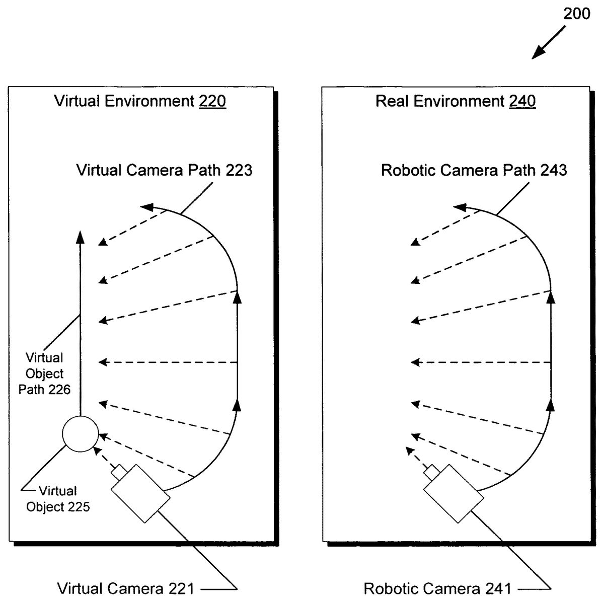
FIG. 2presents a diagram of a robotic camera path configured to match a virtual camera path, according to one embodiment of the present invention. Diagram200ofFIG. 2includes virtual environment220and real environment240. Virtual environment220includes virtual camera221, virtual camera path223, virtual object225, and virtual object path226. Real environment240includes robotic camera241and robotic camera path243. With regards toFIG. 2, it should be noted that virtual environment220corresponds to virtual environment120fromFIG. 1and that real environment240corresponds to real environment140fromFIG. 1. Moreover, althoughFIG. 2only depicts a single virtual camera and a single robotic camera for simplicity, alternative embodiments may use multiple virtual cameras and multiple robotic cameras.
As previously discussed inFIG. 1, master controller150may direct video capture system130to control robotic cameras similarly to virtual cameras in virtual rendering system110.FIG. 2shows an example of this manner of control, where robotic camera241is programmed to follow the movements of virtual camera221. For example, virtual camera221may be programmed to focus on the movement of virtual object225following virtual object path226. Thus, virtual camera221may follow virtual camera path223, with camera orientation following virtual object path226as indicated by the dotted arrows. Virtual camera path223may then be recorded and programmed into robotic camera241of real environment240, so that robotic camera241can follow robotic camera path243mirroring virtual camera path223. Robotic camera241may comprise, for example, a gantry supported fly-by camera, a programmable motion control camera, or another camera system supporting programmable movement.
As shown inFIG. 2, the camera orientation of robotic camera241moves as if it were following virtual object path226within real environment240, even though there is no corresponding real object for virtual object225in real environment240. By using the system described above inFIG. 1, robotic camera241can thus be synchronized to the camera movements of virtual camera221. Composite rendering of real and virtual environments, also known as “augmented reality”, is thus facilitated, as the camera views in virtual environment220and real environment240can be matched according to any desired virtual camera path, opening up limitless possibilities for dynamic camerawork.
The example shown inFIG. 2might be used, for example, to present a dynamic panning camera view showing a hypothetical ball pass defined by virtual object225following virtual object path226, even though such a ball pass never happened in real environment240. The ball pass might be initiated, for example, by a user input originating from input device114aor114binFIG. 1. Thus, a composite render might show a real sports field or stadium background in a video feed captured from real environment240, but with virtual players and a virtual ball rendered in virtual environment220. Thus, the composite render can provide a realistic camera fly-by with photo-realistic background elements from real environment240and a virtual players and a virtual ball rendered from virtual environment220. In this manner, a three-dimensional composite render appearing to have largely photo-realistic quality can be provided to viewers even within the constraints of real-time computer rendering.
FIG. 3presents a diagram of a composite render being generated, according to one embodiment of the present invention. Diagram300ofFIG. 3includes virtual rendering system310, virtually rendered feeds315a-315b, video capture system330, video capture feeds335a-335b, master controller350, composite render355, live broadcast link356, and display357. With regards toFIG. 3, it should be noted that virtual rendering system310corresponds to virtual rendering system110fromFIG. 1, that video capture system330corresponds to video capture system130, that master controller350corresponds to master controller150, that composite render355corresponds to composite render155, that live broadcast link356corresponds to live broadcast link156, and that display357corresponds to display157.
As shown inFIG. 3, virtual rendering system310provides master controller350with virtually rendered feeds315a-315b, while video capture system330provides master controller350with video capture feeds335a-335b. For example, video capture feed335amight correspond to a feed generated by robotic camera241inFIG. 2, whereas virtually rendered feed315amight correspond to a feed generated by virtual camera221inFIG. 2. Virtually rendered feed315bmay correspond to a feed created by an overhead virtual camera providing a bird's eye overview of virtual environment220fromFIG. 2, whereas video capture feed335bmay correspond to a feed created by an overhead robotic camera providing a bird's eye overview of real environment240fromFIG. 2.
Master controller350may then combine virtually rendered feed315aand video capture feed335afor an augmented reality fly-by scene and also combine virtually rendered feed315band video capture feed335bfor an augmented reality bird's eye overview scene. As previously discussed, master controller350may use standard broadcast key technologies to combine the different feeds smoothly so that the juxtaposition of real and virtual elements is visually unobtrusive. Master controller350may then use these combined scenes in composite render355through various presentation methods such as split screen, cascaded or tiled frames, “picture-in-picture”, three-dimensional surfaces, and other formatted layouts. Master controller350may then forward composite render355over live broadcast link356for showing on display357. Master controller350may repeat the above process of generating composite render355in a periodic manner, such as 24, 30, or 60 times per second or higher in order to accommodate a desired video broadcasting framerate.
AlthoughFIG. 3only shows a single composite render355, alternative embodiments may use several composite renders. For example, master controller350may generate multiple composite renders to provide different camera views for multiple broadcast channels, to customize based on a target broadcast region or audience demographics, to focus on a particular team in a sports match, or to support any other broadcasting application that may require multiple concurrent video streams. By adding additional slave rendering engines and robotic cameras, augmented reality rendering systems can be readily scaled and configured to support large-scale projects.
FIG. 4shows a flowchart describing the steps, according to one embodiment of the present invention, by a virtual rendering system and a video capture system may be integrated for outputting a composite render of an augmented reality to a display for videogame broadcast programming. Certain details and features have been left out of flowchart400that are apparent to a person of ordinary skill in the art. For example, a step may comprise one or more substeps or may involve specialized equipment or materials, as known in the art. While steps410through470indicated in flowchart400are sufficient to describe one embodiment of the present invention, other embodiments of the invention may utilize steps different from those shown in flowchart400.
Referring to step410of flowchart400inFIG. 4and diagram100ofFIG. 1, step410of flowchart400comprises receiving input data from a plurality of clients using input devices114a-114bfor modifying virtual environment120presented on displays158-159using slave rendering engines113a-113bof virtual rendering system110. For example, a player for the offense of a sports game may react to display158using input device114ato provide input data, whereas a player for the defense of a sports game may react to display159using input device114b. Slave rendering engines113a-113bmay then interpret the received user input to modify virtual environment120, for example by setting into motion virtual players and a virtual ball as virtual objects within virtual environment120. Additionally, data122aand data122bmay be updated so that virtual cameras121a-121bfollow the focus of the user-initiated actions within virtual environment120.
Referring to step420of flowchart400inFIG. 4and diagram100ofFIG. 1, step420of flowchart400comprises obtaining, from virtual rendering system110, data122aof virtual camera121ain virtual environment120. As shown inFIG. 1, master controller150may query rendering engine controller111for a virtual camera configuration concerning virtual camera121a. Rendering engine controller111may then determine that slave rendering engine113acontrols virtual camera121a, and correspondingly send a request to slave rendering engine113ato retrieve data122a. Data122amay then be retrieved by slave rendering engine113a, for relay back to master controller150via rendering engine controller111. As previously described, data122amay contain various information concerning the configuration of virtual camera121asuch as three-dimensional position and movement, camera focus and view, camera model parameters, and other details.
Referring to step430of flowchart400inFIG. 4and diagram100ofFIG. 1, step430of flowchart400comprises programming video capture system130using data122aobtained from step420to correspondingly control robotic camera141ain real environment140. For example, master controller150may instruct camera motion controller131to program values into data142ato match data122aas closely as possible. As previously discussed, data122amay include three-dimensional coordinates and camera field of view with respect to time. Assuming virtual camera221and robotic camera241correspond to virtual camera121aand robotic camera141a, the result of setting data142ato match data122amay be manifested by robotic camera path243mimicking virtual camera path223, as shown inFIG. 2.
Referring to step440of flowchart400inFIG. 4, diagram200ofFIG. 2, and diagram300ofFIG. 3, step440of flowchart400comprises capturing, from video capture system330, video capture feed335aof real environment240using robotic camera241. Since the motion path of robotic camera241was previously programmed in step430, step430results in master controller350receiving video capture feed335acomprising fly-by footage according to robotic camera path243.
Referring to step450of flowchart400inFIG. 4, diagram200ofFIG. 2, and diagram300ofFIG. 3, step450of flowchart400comprises obtaining, from virtual rendering system310, virtually rendered feed315aof virtual environment220using virtual camera221and showing the modifying of virtual environment220in step410. As previously discussed, user input from step410may affect data122a-122b, which may in turn affect the movement of the virtual cameras and thus virtual camera path223. As shown inFIG. 2, virtual camera path223is defined as an arc with the camera field of view following virtual object225as it progresses through virtual object path226. For example, by a user may initiate the movement of virtual object225by pressing a button mapped to “pass ball” on input device114a. Thus, master controller350may receive virtually rendered feed315acomprising fly-by footage according to virtual camera path223, wherein the feed includes a rendering of virtual object225moving through virtual environment220as initiated by the input data of step410.
Referring to step460of flowchart400inFIG. 4and diagram300ofFIG. 3, step460of flowchart400comprises rendering composite render355by processing video capture feed335afrom step440and virtually rendered feed315afrom step450. As previously discussed, master controller350may accomplish step460using standard broadcast key technology such as chroma key or key/fill techniques to isolate and combine components from each feed to produce a result with a smooth visual juxtaposition of real and virtual elements.
Referring to step470of flowchart400inFIG. 4and diagram300ofFIG. 3, step470of flowchart400comprises outputting composite render355from step460to display357. As shown inFIG. 3, master controller350may send composite render355using live broadcast link356, which might comprise a satellite uplink to a broadcast station for public dissemination. Eventually, composite render355shows on display357, which might comprise the television of a viewer at home.
While the above steps410-470have been described with respect to a single virtual camera, a single robotic camera, and a single composite render, steps410-460may also be repeated as necessary to support multiple virtual cameras, multiple robotic cameras, and multiple composite renders, as previously described. Moreover, more than two input devices might be supported for games having more than two concurrent players. In this manner, the described rendering system can be flexibly scaled to larger projects by increasing the number of slave rendering systems and robotic cameras to handle additional feeds in real-time.
In this manner, virtual games such as competitive sports games can be enhanced with high-impact augmented reality segments by leveraging real environmental footage from synchronized motion control camera systems. This can provide networks with a competitive advantage by drawing in and retaining greater viewership by providing compelling augmented reality content while requiring only minor additional infrastructure outlays over standard rendering systems. Since commodity hardware parts are used, expensive proprietary systems and vendor lockout may be avoided, further reducing total cost of ownership.
From the above description of the invention it is manifest that various techniques can be used for implementing the concepts of the present invention without departing from its scope. Moreover, while the invention has been described with specific reference to certain embodiments, a person of ordinary skills in the art would recognize that changes can be made in form and detail without departing from the spirit and the scope of the invention. As such, the described embodiments are to be considered in all respects as illustrative and not restrictive. It should also be understood that the invention is not limited to the particular embodiments described herein, but is capable of many rearrangements, modifications, and substitutions without departing from the scope of the invention.
Claims
- A method for integrating a virtual rendering system and a video capture system for outputting a composite render to a display, the method comprising: receiving input data from a plurality of clients for modifying a virtual environment presented using the virtual rendering system;obtaining, from the virtual rendering system, a first virtual camera configuration of a first virtual camera in the virtual environment, wherein the first virtual camera configuration includes camera position data, camera field of view orientation data, camera movement data and camera characteristics data;programming the video capture system using the first virtual camera configuration to correspondingly control a first robotic camera in the real environment;capturing, from the video capture system, a first video capture feed of the real environment using the first robotic camera;obtaining, from the virtual rendering system, a first virtually rendered feed of the virtual environment using the first virtual camera, wherein the first virtually rendered feed shows the modifying of the virtual environment;rendering the composite render, based on a target broadcast region, by processing the first video capture feed and the first virtually rendered feed, wherein the composite render includes at least one other scene in a formatted layout, and wherein the composite render further includes a real sports field with at least one virtual player of a virtual game;and outputting the composite render to the display.
- The method of claim 1 , wherein the first virtual camera configuration further includes a first motion path of the first virtual camera in the virtual environment from the common coordinate, and wherein the control of the first robotic camera uses the first motion path from the common coordinate in the real environment.
- The method of claim 2 , wherein the first motion path includes a three-dimensional position with respect to time.
- The method of claim 2 , wherein the first motion path includes a camera orientation or field of view with respect to time.
- The method of claim 1 , wherein the camera characteristics data includes camera lens parameters.
- The method of claim 2 , wherein the first motion path tracks a path of a virtual object.
- The method of claim 6 , wherein the virtual object comprises a virtual ball of a virtual game.
- The method of claim 6 , wherein the virtual object comprises the at least one virtual player.
- The method of claim 2 , wherein the first motion path is based on a predetermined path.
- The method of claim 1 further comprising prior to the rendering of the composite render: obtaining, from the virtual rendering system, a second virtual camera configuration of a second virtual camera in the virtual environment;programming the video capture system using the second virtual camera configuration to correspondingly control a second robotic camera in the real environment;capturing, from the video capture system, a second video capture feed of the real environment using the second robotic camera;and obtaining, from the virtual rendering system, a second virtually rendered feed of the virtual environment using the second virtual camera;wherein the rendering of the composite render further processes the second video capture feed and the second virtually rendered feed.
- A rendering controller for outputting a composite render to a display, the rendering device comprising: a processor configured to: receive input data from a plurality of clients for modifying a virtual environment presented using a virtual rendering system;obtain, from the virtual rendering system, a virtual camera configuration of a first virtual camera in the virtual environment, wherein the first virtual camera configuration includes camera position data, camera field of view orientation data, camera movement data and camera characteristics data;program a video capture system using the virtual camera configuration to correspondingly control a first robotic camera in the real environment;capture, from the video capture system, a first video capture feed of the real environment using the first robotic camera;obtain, from the virtual rendering system, a first virtually rendered feed of the virtual environment using the first virtual camera, wherein the first virtually rendered feed shows the modifying of the virtual environment;render the composite render, based on a target broadcast region, by processing the first video capture feed and the first virtually rendered feed, wherein the composite render includes at least one other scene in a formatted layout, and wherein the composite render further includes a real sports field with at least one virtual player of a virtual game;and output the composite render to the display.
- The rendering controller of claim 11 , wherein the first virtual camera configuration further includes a first motion path of the first virtual camera in the virtual environment from the common coordinate, and wherein the control of the first robotic camera uses the first motion path from the common coordinate in the real environment.
- The rendering controller of claim 12 , wherein the first motion path includes a three-dimensional position with respect to time.
- The rendering controller of claim 12 , wherein the first motion path includes a camera orientation or field of view with respect to time.
- The rendering controller of claim 11 , wherein the camera characteristics data includes camera lens parameters.
- The rendering controller of claim 12 , wherein the first motion path tracks a path of a virtual object.
- The rendering controller of claim 16 , wherein the virtual object comprises a virtual ball of a virtual game.
- The rendering controller of claim 16 , wherein the virtual object comprises the at least one virtual player.
- The rendering controller of claim 12 , wherein the first motion path is based on a predetermined path.
- The rendering controller of claim 11 , wherein prior to the rendering of the composite render the processor is further configured to: obtain, from the virtual rendering system, a second virtual camera configuration of a second virtual camera in the virtual environment;program the video capture system using the second virtual camera configuration to correspondingly control a second robotic camera in the real environment;capture, from the video capture system, a second video capture feed of the real environment using the second robotic camera;and obtain, from the virtual rendering system, a second virtually rendered feed of the virtual environment using the second virtual camera;wherein the processor is configured to render the composite render by further processing the second video capture feed and the second virtually rendered feed.
Disclaimer: Data collected from the USPTO and may be malformed, incomplete, and/or otherwise inaccurate.