U.S. Pat. No. 8,784,171
Method and apparatus for modeling a track in video games using arcs and splines that enables efficient collision detection
AssigneeNintendo Co., Ltd.
Issue DateAugust 8, 2003
Illustrative Figure
Abstract
A method and apparatus for modeling a track in video games that enables efficient collision detection between a game object (such as a racecar wheel) and the track. The invention provides an infinitely smooth track for use in collision detection through the novel use of arcs and splines. The invention enables relatively small amounts of data to be used to model and express relatively large gameplay courses, such as race tracks and the like. The arcs and splines enables quick and efficient look-up of the location of the tire on the track and calculation of the distance from the wheel to the track for loading purposes.
Description
DETAILED DESCRIPTION OF THE PREFERRED EMBODIMENTS In accordance with the instant invention, arcs are used to represent the curved sections of a track, and splines (e.g., one-dimensional Hermite Splines) are defined around the arcs to specify the height changes for each arc (e.g., each side of the road), thereby enabling complex roads (or other tracks) to be modeled in a very efficient and smooth manner, as compare to prior art techniques. The invention defines a track by defining straight track sections (defined by length) and arced track sections (defined by radius and angles). As explained is greater detail below, splines are defined through the arcs for use in defining the track height through the arc. The length and angles of the arced sections can vary such that any desired type of curved section can be defined for the track.FIG. 7shows an exemplary arc section240as used in accordance with the instant invention. A radius242is defined together with an angle250for the arc. In this way an arc section is defined. Within that arc section, a maximum radius246and minimum radius248are defined in order to define a track section244between arcs268and270. Other arc sections, like252and256can also be defined in this manner to express banks, grassy areas or any other outer or inner section for the track244. These outer or inner sections are not required, but can be used to provide additional features for the track, such as off-road sections. The track section244includes four end points258,260,264and262that represent the end points of the arcs268and270and define an arc section for the track. In accordance with the invention, a complete track is made by defining a plurality of these arc sections244, each with a different radius (and min. and max.) and angle and then connecting the arcs together to form the track. The track can also include straight sections. ...
DETAILED DESCRIPTION OF THE PREFERRED EMBODIMENTS
In accordance with the instant invention, arcs are used to represent the curved sections of a track, and splines (e.g., one-dimensional Hermite Splines) are defined around the arcs to specify the height changes for each arc (e.g., each side of the road), thereby enabling complex roads (or other tracks) to be modeled in a very efficient and smooth manner, as compare to prior art techniques. The invention defines a track by defining straight track sections (defined by length) and arced track sections (defined by radius and angles). As explained is greater detail below, splines are defined through the arcs for use in defining the track height through the arc. The length and angles of the arced sections can vary such that any desired type of curved section can be defined for the track.FIG. 7shows an exemplary arc section240as used in accordance with the instant invention. A radius242is defined together with an angle250for the arc. In this way an arc section is defined. Within that arc section, a maximum radius246and minimum radius248are defined in order to define a track section244between arcs268and270. Other arc sections, like252and256can also be defined in this manner to express banks, grassy areas or any other outer or inner section for the track244. These outer or inner sections are not required, but can be used to provide additional features for the track, such as off-road sections. The track section244includes four end points258,260,264and262that represent the end points of the arcs268and270and define an arc section for the track. In accordance with the invention, a complete track is made by defining a plurality of these arc sections244, each with a different radius (and min. and max.) and angle and then connecting the arcs together to form the track. The track can also include straight sections.
FIG. 10shows an exemplary track280defined in accordance with the present invention. The track280is defined as a series of straight sections (282,284,285,286) and a series of different arced sections (288,290,292,294,296). In accordance with the invention, the track (straights and arcs) are first defined in top-down, plan 2D manner and then the height of the track is applied later. As a result, one can use aerial maps of real racetracks and then lay out the series of straights and arcs in a manner that corresponds to the real track. All real-world tracks have turns defined by the number of degrees and the meter radius of the corner. Thus, the invention is very applicable to real-world modeling of tracks. In addition to the track itself, medians, grass areas, banks and/or other inner or outer arced sections can be defined for each arced road section.FIG. 10shows these additional outer arched sections (300,302,304) for arc section292only. Each of these outer arc sections (300,302,304) can then be defined with a different texture to represent various off road terrain or the like. As can be seen inFIG. 10, the radius and angle for each arc is different, thereby providing a different type of road section. Once the various arcs are defined, they can be combined and repeated to define a very long and complex track. As indicated on track sections282and292, any specific location on the track can be defined by the normalized values U and V, wherein V represents the normalized distance from the origin and U represents the distance along the track section.
Once the 2-D arcs are defined, as explained in connection withFIGS. 7 and 10, the splines are then defined to add height to each road section. The spline data can also be used to, for example, add objects to the track, like a fence. In other words, the spline data can be used to generate graphics for the track. As a result, the invention provides the option of having an artist first lay out the track and then apply the straights and arcs thereon, or, alternatively, having the graphics generated directly from the defined arcs and straights. The inventor has developed a test track using the instant invention wherein sixty random arcs are joined together to define a five mile course. Thus, the invention makes it very easy to create very long and interesting courses with many objects, such as trees, and using far less resources as compared to the polygon method.
In accordance with the invention, the elevation of the arcs are defined by specifying an elevation (e.g., in meters) and a height change for the start and the end points of the arc. Specifically, with reference toFIG. 7, the height and height change at each of the end points258,260,262and264are defined. Then the spline data is generated using a Hermite Spline interpolation. As one skilled in the art understands, a spline is a parametric curve defined by some control points. A Hermite Spline is known as a curve (typically cubic) for which the user provides the end points of the curve and the parametric derivatives of the curve at the end points. A point on a Hermite curve can be obtained, in a known manner, by multiplying each control point by some function and summing. In other words, in the instant invention, the height and the height change is blended from one end point (e.g.,262) to the other end point (258) over the arc270, thereby defining the Hermite Spline data for the arc270.FIG. 13provides a simplified view of this spline generation. A height and rate of height change are defined for both end points262and258, and then the Hermite Spline interpolation is used to determine the spline304therebetween.
In accordance with the invention, a bounding box is defined for each arc and straight section of the track. For an arc section the bounding box is preferably a box that encompasses the four end points of the track section. An exemplary bounding box320is shown inFIG. 12for arc section322. For straight track sections, the bounding box simply conforms to the track section. The bounding boxes are used to quickly determine if a wheel is anywhere within the area defined by the bounding box. For example, as shown inFIG. 12, the bounding box320is tested to see if the wheel324is within the bounding box. This simplifies testing for the location of the wheels by doing a rough test first in order to eliminate many bounding boxes (and the corresponding sections of track) as possibilities for the location of the wheels. Once it is determined that a wheel is in a bounding box, a 2D test is run to determine whether the wheel in the bounding box is within the minimum and maximum radius of the arc segment. For example, when the bounding box320ofFIG. 12is checked, it is determined that the wheel324is within the box. Obviously, if the wheel324is not in the bounding box320, the wheel cannot be within the arc section322. On the other hand, if the wheel is in the bounding box and the wheel is within the arc segment, a calculation is done to determine how far the wheel is around the arc (arc angle U), in order to determine how the spline is interpolating at that point. Thus, normalized U and V distance values (0 to 1 values) are obtained. With these values, the height and elevation change of the arc at the determined points can be determined, thereby providing the data for the Hermite Spline. Next, a temporary plane is found for arc angle U, which is the plane in which the collision may occur. The temporary plane is defined by the normal perpendicular to the road at angle U and the distance from the origin. Then, a calculation is performed to find the distance between the wheel (modeled as a sphere) and that plane. In advantage of the invention is that the above process only needs to be done once per arc segment which is much more efficient than a polygon technique. Once the distance is obtained, it is known how far the tire has embedded itself into the road, thereby enabling a corresponding force to be applied to the tire. This process simulates the compression of the tire under weight. This process is also illustrated inFIG. 8, wherein the tire206is shown as being embedded into the road224by distance D. This distance D determines how much force is being applied to the tire at that time. Also, as shown inFIG. 9, because the angle of the temporary plane is known, the camber angle of the tire206relative to the normal for the road224can also be determined for simulation purposes (e.g., adjusting frictional values). The force on the tire206caused by the distance D can be changed to simulate tire air pressure. Once the force is applied to the tire, the car modeling causes resulting forces to the car through the car suspension and body modeling (seeFIGS. 4 and 6), thereby providing a very realistic auto racing game or the like.
FIG. 11shows a simplified flow chart of the main steps performed in accordance with the preferred embodiment of the instant invention in order to perform collision detection for an arced section of track (e.g., section292ofFIG. 10). As explained above, the first step (400) involves checking the bounding boxes for the track sections to see if a wheel is within the bounding box. In the next step (402), the minimum and maximum radius of the arc segment is checked to see if the wheel is within the arc segment. If the wheel is in the arc segment, the distance V (normalized) from the origin is calculated. Then, the normalized arc angle U is calculated (step404), thereby indicating how far the wheel is around the arc. Then in step406, the spline height and change is calculated for arc angle U. The temporary plane is then defined for arc angle U (step408). Finally, the distance D to the sphere (wheel) from the track is determined (step410). This distance D is then used in the manner described above for tire load modeling and effect.
FIG. 14shows a simplified flow chart of the main steps performed in accordance with the preferred embodiment of the instant invention in order to perform collision detection for a straight section of track (e.g., section282ofFIG. 10). The first step (500) involves checking the bounding boxes for the track sections to see if a wheel is within the bounding box. Of course, for a straight section of track this step determines if the wheel is within the track section, due to the fact that the bounding box preferably matches the track section. In the next step (502), the minimum and maximum width boundaries are checked (optional) to confirm if the wheel is within the segment and then the normalized distance (V) that the wheel is from the lower edge of the track is determined. Then, the distance U is calculated (step504), thereby indicating how far the wheel is along the straight section. Then in step506, the spline height and change is calculated for distance U. The temporary plane is then defined for distance U (step508). Finally, the distance D to the sphere (wheel) from the track is determined (step510). This distance D is then used in the manner described above for tire load modeling and effect.
FIG. 15shows a screen shot of an exemplary track showing polygons and normals of a type in which the instant invention can be used. In order to further illustrate and exemplary embodiment of the invention,FIG. 16provides a screen shot of an exemplary track having arc sections defined in accordance with the instant invention.FIG. 17provides another screen shot of an exemplary track having arc sections defined in accordance with the instant invention. Finally,FIG. 18is a screen shot of an exemplary track showing the bounding boxes defined for each track section in accordance with the instant invention.
Example Illustrative Implementation
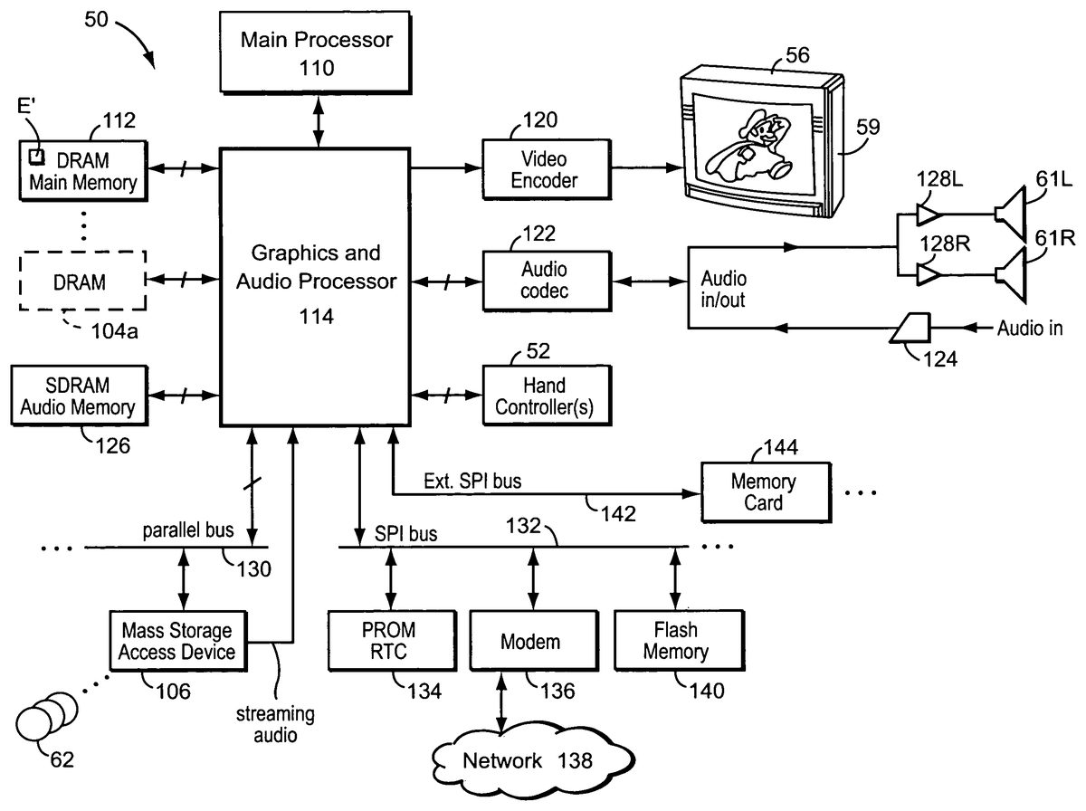
FIG. 19shows an example interactive 3D computer graphics system50. System50can be used to play interactive 3D video games with interesting animation and collision detection provided by a preferred embodiment of this invention. System50can also be used for a variety of other applications.
In this example, system50is capable of processing, interactively in real time, a digital representation or model of a three-dimensional world. System50can display some or the entire world from any arbitrary viewpoint. For example, system50can interactively change the viewpoint in response to real time inputs from handheld controllers52a,52bor other input devices. This allows the game player to see the world through the eyes of someone within or outside of the world. System50can be used for applications that do not require real time 3D interactive display (e.g., 2D display generation and/or non-interactive display), but the capability of displaying quality 3D images very quickly can be used to create very realistic and exciting game play or other graphical interactions.
To play a video game or other application using system50, the user first connects a main unit54to his or her color television set56or other display device by connecting a cable58between the two. Main unit54produces both video signals and audio signals for controlling color television set56. The video signals are what controls the images displayed on the television screen59, and the audio signals are played back as sound through television stereo loudspeakers61L,61R.
The user also needs to connect main unit54to a power source. This power source may be a conventional AC adapter (not shown) that plugs into a standard home electrical wall socket and converts the house current into a lower DC voltage signal suitable for powering the main unit54. Batteries could be used in other implementations.
The user may use hand controllers52a,52bto control main unit54. Controls60can be used, for example, to specify the direction (up or down, left or right, closer or further away) that a character or other object (such as a racecar) displayed on television56should move within a 3D world. Controls60also provide input for other applications (e.g., menu selection, pointer/cursor control, etc.). Controllers52can take a variety of forms. In this example, controllers52shown each include controls60such as joysticks, push buttons and/or directional switches. Controllers52may be connected to main unit54by cables or wirelessly via electromagnetic (e.g., radio or infrared) waves.
To play an application such as a game, the user selects an appropriate storage medium62storing the video game or other application he or she wants to play, and inserts that storage medium into a slot64in main unit54. Storage medium62may, for example, be a specially encoded and/or encrypted optical and/or magnetic disk. T the user may operate a power switch66to turn on main unit54and cause the main unit to begin running the video game or other application based on the software stored in the storage medium62. The user may operate controllers52to provide inputs to main unit54. For example, operating a control60may cause the game or other application to start. Moving other controls60can cause controlled objects to move in different directions or change the user's point of view in a 3D world. Depending upon the particular software stored within the storage medium62, the various controls60on the controller52can perform different functions at different times.
As also shown inFIG. 19, mass storage device62stores, among other things, the collision detection engine E used to perform the collision detection and other features described in detail herein. The collision detection engine E in the preferred embodiment makes use of various components of system50shown inFIG. 10Bincluding:a main processor (CPU)110,a main memory112, anda graphics and audio processor114.
In this example, main processor110(e.g., an enhanced IBM Power PC750) receives inputs from handheld controllers52(and/or other input devices) via graphics and audio processor114. Main processor110interactively responds to user inputs, and executes a video game or other program supplied, for example, by external storage media62via a mass storage access device106such as an optical disk drive. As one example, in the context of video game play, main processor110can perform collision detection and animation processing in addition to a variety of interactive and control functions.
In this example, main processor110generates 3D graphics and audio commands and sends them to graphics and audio processor114. The graphics and audio processor114processes these commands to generate interesting visual images on display59and interesting stereo sound on stereo loudspeakers61R,61L or other suitable sound-generating devices. Main processor110and graphics and audio processor114also perform functions to support and implement the preferred embodiment collision detection engine E based on instructions and data E′ relating to the engine that is stored in DRAM main memory112and mass storage device62.
As further shown inFIG. 20, example system50includes a video encoder120that receives image signals from graphics and audio processor114and converts the image signals into analog and/or digital video signals suitable for display on a standard display device such as a computer monitor or home color television set56. System50also includes an audio codec (compressor/decompressor)122that compresses and decompresses digitized audio signals and may also convert between digital and analog audio signaling formats as needed. Audio codec122can receive audio inputs via a buffer124and provide them to graphics and audio processor114for processing (e.g., mixing with other audio signals the processor generates and/or receives via a streaming audio output of mass storage access device106). Graphics and audio processor114in this example can store audio related information in an audio memory126that is available for audio tasks. Graphics and audio processor114provides the resulting audio output signals to audio codec122for decompression and conversion to analog signals (e.g., via buffer amplifiers128L,128R) so they can be reproduced by loudspeakers61L,61R.
Graphics and audio processor114has the ability to communicate with various additional devices that may be present within system50. For example, a parallel digital bus130may be used to communicate with mass storage access device106and/or other components. A serial peripheral bus132may communicate with a variety of peripheral or other devices including, for example:a programmable read-only memory and/or real time clock134,a modem136or other networking interface (which may in turn connect system50to a telecommunications network138such as the Internet or other digital network from/to which program instructions and/or data can be downloaded or uploaded), andflash memory140.
A further external serial bus142may be used to communicate with additional expansion memory144(e.g., a memory card) or other devices. Connectors may be used to connect various devices to busses130,132,142.
Collision detection engine E may be implemented for example by software executing on main processor110.
As will be understood by one skilled in the art, various changes and modifications may be made in accordance with the invention. Thus, the above description is meant to be exemplary only and is not meant to limit the invention to the specific embodiments disclosed. The invention is not limited to race tracks or other road-like courses, but can be applied to any suitable gaming environment where smooth surface and efficient collision detection are desired.
Claims
- A computer-implemented method for modeling a track, the method being performed using a computer including at least one processor to execute instructions tangibly stored on a computer readable storage medium, the method comprising: defining, using the computer, a curved outer arc and an inner arc which together define an arc track section therebetween, and using splines to define height data for the arc track section, wherein a plurality of straight track sections are defined, each said straight track section being defined by a length and a width, and wherein each of the outer arc, the inner arc, and the curved arc track section is not defined using a plurality of straight track sections.
- The method of claim 1 , further including defining a plurality of said arc track sections and connecting the plurality of arc track sections together to form a continuous track.
- The method of claim 1 , further including defining an additional curved arc outside the outer arc to define an outer section of the arc track section and applying a different texture to the arc track section and the outer section.
- A computer-implemented method for modeling a track, the method being performed using a computer including at least one processor to execute instructions tangibly stored on a computer readable storage medium, the method comprising: defining, using the computer, a curved outer arc and an inner arc which together define an arc track section therebetween, and using splines to define height data for the arc track section, wherein the splines are one-dimensional Hermite Splines.
- A computer-implemented method for modeling a track, the method being performed using a computer including at least one processor to execute instructions tangibly stored on a computer readable storage medium, the method comprising: defining, using the computer, a plurality of curved arc track sections, wherein each arc track section is defined by an outer arc and an inner arc which together define the arc track section therebetween, and further wherein each arc track section uses splines to define height data for the arc track section;defining, using the computer, a plurality of straight track sections, wherein each straight track section is defined by a length and width;and connecting the plurality and arc track sections and straight track sections together to form a continuous track, using the computer, wherein each said outer arc, inner arc, and curved arc track section is not defined using a plurality of straight track sections.
- The method of claim 5 , wherein the height of the arcs are defined by specifying an elevation and a height change for a starting point and an ending point of the arc and generating a spline using interpolation.
- A computer-implemented for modeling a track for a video game, the method being performed using a computer including at least one processor to execute instructions tangibly stored on a computer readable storage medium, the method comprising: defining, using a computer, a curved outer arc and an inner arc which together define an arc track section therebetween, using splines to define height data for the arc track section, and using the splines to add graphics to the track, wherein a plurality of straight track sections are defined, each said straight track section being defined by a length and a width, and wherein each of the outer arc, the inner arc, and the curved arc track section is not defined using a plurality of straight track sections.
- A computer-implemented method of making track for use in a video game, the method being performed using a computer including at least one processor to execute instructions tangibly stored on a computer readable storage medium, the method comprising: defining, using the computer, a plurality of curved arcs, wherein each arc is defined by a common origin and angle and a different radius and arc sections are defined between adjacent arcs, applying a different texture to each arc section, and using splines to add height information to each arc section, wherein a plurality of straight track sections are defined, each said straight track section being defined by a length and a width, and wherein each said arc and arc section is not defined using a plurality of straight track sections.
- The method of claim 8 , wherein the height information for each arc section is defined by specifying an elevation and a height change for a starting point and an ending point of the respective arc and generating a spline using interpolation.
Disclaimer: Data collected from the USPTO and may be malformed, incomplete, and/or otherwise inaccurate.