U.S. Pat. No. 8,753,208
SEQUENTIAL MODE AND MANUAL MODE SPEED CONTROLLER FOR VIDEO GAMES
AssigneeGuillemot Corporation
Issue DateJune 3, 2011
Illustrative Figure
Abstract
The invention relates to a speed controller, in particular for video games, capable of operating according to a sequential mode and a manual mode comprising: a support casing (1), a lever (2) hingeably mounted on said support casing and capable of pivoting from a neutral position, in a longitudinal direction around a transversal axis and in a transversal direction around a longitudinal axis, and detection means for detecting, in the manual mode, at least two different positions of the lever obtained by the pivoting thereof in at least the longitudinal direction from the neutral position and, in the sequential mode, at least two different positions of the lever, characterized in that the detection means are capable of detecting, in the sequential mode, at least two different positions of the lever obtained by the pivoting thereof in the transversal direction from the neutral position.
Description
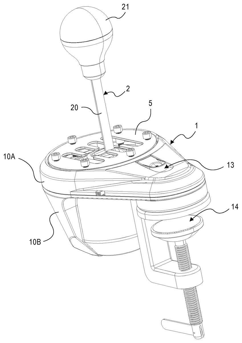
DETAILED DESCRIPTION The invention relates to a speed controller for video games which may operate in a manual mode, also called H mode, and a sequential mode, also called automatic mode. The term “video game” in particular encompasses recreational video games, serious games and vehicle driving or piloting simulator software. With reference toFIGS. 1 to 4, the speed controller comprises:a support casing1,a lever2comprising a rod20equipped at its upper free end with a preferably removable knob21,means3for articulating the speed controller lever to make it possible to pivot the lever2, from a neutral position, in a longitudinal direction around a transversal axis Y and in a transversal direction around a longitudinal axis X, anddetection means4capable of detecting, in the manual mode, the neutral position and eight different positions of the lever2obtained by pivoting the lever2in the longitudinal direction and the transversal direction from the neutral position and, in the sequential mode, the neutral position and two different positions of the lever2transversally shifted with respect to the neutral position and obtained by pivoting the lever2in said transversal direction from the neutral position. Thus, in the sequential mode, the user moves the speed controller lever along the neutral row of the lever2. As will be seen further down, this new configuration particularly makes it possible to use already-existent transversal elastic return means of the speed controller to bring back, in the sequential mode, the lever2towards the neutral position. The different positions of the speed controller lever in the manual mode and in the sequential mode are illustrated byFIGS. 5 and 6. In addition to the neutral position referenced N, the sequential mode comprises two positions, referenced S1and S2, arranged on either side of the neutral position N, and the manual mode comprises eight positions referenced M1to M8, each two facing each other with respect ...
DETAILED DESCRIPTION
The invention relates to a speed controller for video games which may operate in a manual mode, also called H mode, and a sequential mode, also called automatic mode.
The term “video game” in particular encompasses recreational video games, serious games and vehicle driving or piloting simulator software.
With reference toFIGS. 1 to 4, the speed controller comprises:a support casing1,a lever2comprising a rod20equipped at its upper free end with a preferably removable knob21,means3for articulating the speed controller lever to make it possible to pivot the lever2, from a neutral position, in a longitudinal direction around a transversal axis Y and in a transversal direction around a longitudinal axis X, anddetection means4capable of detecting, in the manual mode, the neutral position and eight different positions of the lever2obtained by pivoting the lever2in the longitudinal direction and the transversal direction from the neutral position and, in the sequential mode, the neutral position and two different positions of the lever2transversally shifted with respect to the neutral position and obtained by pivoting the lever2in said transversal direction from the neutral position.
Thus, in the sequential mode, the user moves the speed controller lever along the neutral row of the lever2. As will be seen further down, this new configuration particularly makes it possible to use already-existent transversal elastic return means of the speed controller to bring back, in the sequential mode, the lever2towards the neutral position.
The different positions of the speed controller lever in the manual mode and in the sequential mode are illustrated byFIGS. 5 and 6. In addition to the neutral position referenced N, the sequential mode comprises two positions, referenced S1and S2, arranged on either side of the neutral position N, and the manual mode comprises eight positions referenced M1to M8, each two facing each other with respect to the neutral position N. Each one of these positions corresponds to a particular position of the lower end of the speed controller lever2.
The support casing1is provided, in its upper portion, with a preferably removable gate5, for guiding the travel of the speed controller lever between the neutral position and the different positions of the speed controller lever in both manual and sequential modes. It also comprises an upper cover10A and a lower cover10B assembled by clipping or screwing.
Gate5is mounted on the support casing1and comprises, for the passage of the lever2, a transversal slot51and eight longitudinal slots52each opening into the transversal slot as illustrated onFIG. 7. The transversal slot51is positioned and sized in order to guide the travel of the lower free end of the lever2between the neutral position N and the two positions S1and S2of the sequential mode. Likewise, each one of the longitudinal slots52is positioned and sized in order to guide the travel of the lower free end of the speed controller lever between the transversal slot51and one of the positions M1to M8of the manual mode.
These positions are detected by the detection means4. These detection means comprise a three-axis Hall-effect sensor41associated to a magnet42. A three-axis Hall-effect sensor provides great precision typically greater than that of a potentiometer or an optical encoder. Its encumbrance is also lower. The three-axis Hall-effect sensor41is mounted on a printed circuit board43, itself mounted on a stationary portion of the support casing, and the magnet42is mounted on the lower free end of the lever2opposite to the Hall-effect sensor.
According to an alternative, the Hall-effect sensor41is mounted on the lower free end of the lever2and the magnet42is mounted opposite to the Hall-effect sensor on a stationary portion of the support casing.
Advantageously, the speed controller comprises a second removable gate6which may be mounted on the support casing1over gate5or to replace gate5, this second gate being specifically designed for the sequential mode to guide the travel of the lower free end of the lever2between the neutral position N and the two positions S1and S2of the sequential mode. As illustrated inFIG. 8, the gate6only comprises a transversal slot61sized in order to allow for the travel of the speed controller lever lower free end only between neutral position N and positions S1and S2in the sequential mode.
Advantageously, the length of the transversal slot61is lower than the length of the transversal slot51to reduce the travel of the speed controller lever in the sequential mode, the positions S1and S2thus being reached when the speed controller lever2is in abutment against the ends of the transversal slot61.
Alternatively, instead of gate6, shutters which may cover at least partially the longitudinal slots52of the gate5in order to guide the speed controller lever in the sequential mode may be provided.
In order to modify the orientation of the neutral row and improve the ergonomics of the speed controller, the support casing1comprises a stationary set11and a movable set12whereon the speed controller lever is hingeably mounted. The movable set12is mounted movable in rotation on the stationary set around a rotational axis Z which is substantially perpendicular to axes X and Y as illustrated inFIG. 9.
The stationary set11comprises a support plate111provided with a circular opening112through which the movable set12is mounted movable in rotation. This plate is shown on its own inFIG. 10. In this figure, the external outline of the support plate111is oval such that the support plate11is rotationally locked with respect to the upper cover10A and/or the lower cover10B. It could be of different shape.
The movable set12comprises a circular-shaped rim120, movable in rotation around axis Z in the opening112and a support frame121fastened to the lower wall of the rim. The rim defines an inner passage traversed by the speed controller lever.
As illustrated inFIG. 11, the rim120is made of an upper rim120A and a lower rim120B. The lower rim120B is provided for rotating around axis Z inside the opening112. To this end, the external diameter of the lower rim120B is substantially equal to the diameter of the opening112. The upper rim120A rests upon studs122on the lower rim120B.
The gate5is mounted on the upper wall of the upper rim120A. Fixing screws123are provided for fixing gate5, and/or if necessary gate6, on the upper rim120A. These screws also serve for fixing upper rim120A on the lower rim120B.
As shown in theFIGS. 3 and 4, the support frame121is generally U shaped. It comprises a base124and two parallel lateral branches125extending from the base. The printed circuit board43supporting the three-axis Hall-effect sensor41is mounted on the upper side of the base124. Furthermore, the means3for articulating the speed controller lever are placed between the two lateral branches125.
As specifically shown inFIG. 4the means3for articulating the speed controller lever comprise a casing31pivotally mounted between the two lateral branches125by means of two pivots32and33arranged on two lateral walls of the casing31. These two pivots are placed on the longitudinal axis X and are provided to cause the casing31to pivot around the axis X. These two pivots are rotatably mounted within the openings126provided in the lateral branches125. The casing31further comprises a shaft34defining the transversal axis Y. This shaft is mounted between two longitudinal walls of the casing. The shaft34is provided to pivot within openings provided in the longitudinal walls of the casing. This pivoting assembly is known per se. The casing31also comprises known means (not shown) capable of maintaining the speed controller lever in one of the positions M1to M8in the manual mode.
Elastic return means7are mounted between the casing31and the support frame121to elastically bring the speed controller lever towards the neutral position. Such transversal elastic return means already exist in current gear shift boxes to return a gear shift lever back towards the neutral position along a transversal direction. Usually, they are only useful in the manual mode. According to the invention, they are also useful in the sequential mode.
The support casing1also comprises means13for locking in rotation the movable set12onto the stationary set11. The locking means13are able to lock the movable set in at least two locking positions, namely a so-called manual position for the manual mode and a so-called sequential position for the sequential mode, angularly shifted by 90° from each other.
To this end, the locking means13comprises a catch131mounted movable in translation on a support plate111and capable of cooperating with at least two recesses132and133provided in the external wall of the upper rim120A to lock the rotation of the rim. Recesses132and133are angularly shifted by 90°. The catch131is provided with a spur131A capable of being engaged in recess132in order to lock the movable set in the manual position. The spur131A further engages into the recess133in order to lock the movable set in the sequential position. Additional recesses134are also provided in the upper rim to rotationally lock the movable set into other angular positions. A return spring136is provided to maintain the catch131in recesses132,133or134.
Alternatively, the catch131is cancelled so as to avoid the mechanical looseness caused by such a locking means. It is replaced by another locking means for example, by a tightening carried out by two screws acting between the upper rim120A and the lower rim which is secured to the support frame121. After tightening, the screw heads are located in housings made in the upper rim such as not to overlap the upper surface thereof. These screws cross the opening112of the support plate111. The upper rim and the lower rim are thus provided to rotate around axis Z. In this alternative, the external diameter of the upper rim and lower rim is substantially higher than the diameter of the opening112. Consequently, by tightening these screws, the upper rim120A (the studs of the upper rim) and the lower rim tightly press the support plate111between them. It is thus understood that after having loosened these screws, the upper rim and the support frame121may pivot with respect to the support plate111. The advantage of such a locking means is that it does not restrict the number of angular positions that may be adopted by the movable set.
The support casing1also comprises U-bolt type or clamp type fixing means14for attachment to a piece of furniture, such as a table, a desk or any support inside a cockpit/driver compartment/pilot house. These fixing means make it possible to easily modify the location of the speed controller by loosening the means14.
In order to prevent foreign bodies from entering the speed controller mechanism, means for shutting-off opening112are advantageously provided, for example rubber bellows comprising an opening for the rod20or two thin brushes arranged on either side of the neutral row. These shut-off means become deformed when the lever2substantially leaves the rest position and resume their form when the lever2returns to the rest position.
Advantageously, the area of the rod20which may contact gates5and/or6is covered with a Teflon ring to limit friction between these pieces.
In a particular embodiment, the rod21is hollow and the knob21houses a known device for generating vibrations or shocks consisting for example, in a movable mass and an electric motor supplied in power and controlled by the processing circuit or an external device for processing data. The aim of this vibration or shock generating device is to cause a user to feel the vibrations of the simulated vehicle when he/she is holding the lever, for example vibrations corresponding to a sub-regime or a shock corresponding to the shifting of a gear, or even vibrations simulating the implementation of an anti lock brake system, etc.
A mode selector button113is provided at the support plate so that the user may select the operating mode of the speed controller: manual mode or sequential mode.
Alternatively, a device for automatically detecting the rotation of the movable set12to change from the manual mode to the sequential mode or vice versa may be provided.
According to another alternative, instead of or in addition to a device for automatically detecting the rotation of the movable set12, a device for automatically detecting the presence or absence of a gate that is specific to a speed controller mode may be provided in order to change automatically from one mode to another. To this end, one or several presence sensors for example, of push button type or rubber carbon-contact dome type, may be housed in the rim120. Each presence sensor opens or closes a circuit according to whether an object of the gate, for example a protrusion positioned at a specific location on the gate, exerts pressure on the sensitive portion of the presence sensor and thus sufficiently deforms a flexible blade or the rubber dome to change the status of the sensor, thus making it change from an open status to a closed status or vice versa.
Furthermore, the signals issued from the Hall-effect sensor41and the selector button113are transmitted towards a processing circuit that is not shown which can be embedded or not within the speed controller. The Hall-effect sensor41may also be integrated within the processing circuit.
The speed controller has been described above as a speed selecting apparatus capable of operating according to a manual mode and a sequential mode.
According to another application, the speed controller of the invention is used to simulate a hand brake. In this application, the lever2pivots around the longitudinal axis X, in a transversal direction between two different positions, a first position corresponding to the absence of braking and a second position transversally shifted from the first position corresponding to a maximum braking. The first position advantageously corresponds to the neutral position of the speed controller when it operates as a speed selecting apparatus.
In this application, the user moves the lever in the transversal slot (neutral row) to control the braking and, if the first position corresponds to the previously defined neutral position N, the lever pivots in the transversal slot only on one side of the neutral position.
In another application, the speed controller may be used both as a hand brake and a manual accelerator. In this application, the user also preferably uses the neutral row of the manual mode for the travel of the lever2. The lever2pivots around the longitudinal axis X, in a transversal direction, between two positions on either side of the neutral position. A first position is the maximum speed control position and the second position is the maximum braking control position. Preferably, the second position is opposed to the first position with respect to the neutral position. Thus, in this application, the lever pivots in the transversal slot on either side of the neutral position.
Whether it be to simulate a speed selecting apparatus, an accelerator or a brake (hand brake, for example), the speed controller is used for detecting at least two different positions of the speed controller lever and these positions correspond to a speed parameter of the simulated vehicle. In these different applications, the speed controller such as previously described acts to control the speed. In the first application, the speed controller is used to select a gear. In the handbrake application, the speed controller is used to select the braking force to be opposed to the rotation of the vehicle wheels, which is also equivalent to controlling the speed of this vehicle. In the brake and accelerator application, the speed controller is used to select the required motor power, which is also equivalent to controlling the vehicle speed.
The selector button113is used to select the required operating mode: speed selection manual mode, speed selection sequential mode, hand-brake only mode or hand brake and accelerator mode.
Hereinafter, the use of the speed controller of the invention in the hand brake application as well as the possible modifications which may be brought to it for this application will be described.
In this application, the lever2travels in the transversal slot (neutral row of the manual mode). The transversal elastic return means7are used to bring the lever2towards the neutral position corresponding to the absence of braking. It is worth noting that it is not necessary to provide means for locking the lever2in its brake position in this hand brake application. In fact, the usefulness of a parking position, wherein the lever2is locked into maximum brake position, is low for most video games.
The rest position of the lever2(when the user is not exerting action on the lever) is located in the neutral row at the intersection with the longitudinal direction corresponding to referenced positions M3and M4. InFIGS. 1 and 3, the lever2is represented in the rest position. The rest position of lever2is thus shifted with respect to the middle of the neutral row. When the speed controller is used as hand brake, the user moves the lever2along the neutral row of the speed controller. The shifting of the rest position with respect to the middle of the neutral row makes it possible to obtain a greater travel of the lever on one side of the rest position. When the speed controller is used as a hand brake, the lever2thus travels on the side of the rest position which offers a longer clearance for the lever, thus allowing a more precise selection of the braking force.
For this application, the speed controller comprises a third removable gate which may be mounted on the support casing1, instead of gate5, or over gate5, this third gate being specifically designed to guide the travel of the lower free end of the lever2between the neutral position N (position of the lever2in abutment against a first end of the slot, and substantially corresponding to the rest position of the lever2) and the maximum braking position (position of the lever2in abutment against the other end of the slot). This third gate solely comprises a transversal slot sized to allow, in the hand-brake only mode, the travel of the lower free end of the speed controller lever only between these two positions. Advantageously, the length of the slot of this third gate is comprised between the length of slot51and the length of the slot61. However, the slot of this third gate may be longer than slot51in order to give the lever2a greater travel.
It is possible to provide, at the end of the transversal slot of the third gate, a longitudinal slot opening into the transversal slot in order to lock the lever2thereto in the maximum braking position. This longitudinal slot makes it possible to simply create a parking position for the simulated vehicle.
When the lever2of the speed controller is used as a speed selecting lever, the speed controller provides digital information. In other words, when the lever2is used as a gear shift lever, the speed controller provides information on the state (1 or 0) corresponding to each position N and M1to M8in the manual mode or to each position N and S1to S2in the sequential mode. For example, if lever2is used as a gear shift lever in the sequential mode, and when the speed controller lever is in the position corresponding to S1, the speed controller provides the information S1=1, N=0 and S2=0.
Preferably, when the speed controller is used as a hand brake, the speed controller provides analog information to have more precision as to the braking force required by the user. In other words, when the lever2is used as a hand brake lever, the speed controller provides a value comprised in an interval, for example a value ranging between 0 and 256, corresponding to the angular position of the lever2, the value 0 corresponding for example to the neutral position of the lever (no braking of the wheels of the simulated vehicle) and the value 256 corresponding to the position of the lever2in abutment against the end which is opposite from the neutral position (maximum braking of the wheel speed of the simulated vehicle).
Advantageously, the speed controller is provided with an ergonomic accessory that substantially reproduces the shape of the hand brake lever and is placed on the rod20instead of the knob21for this hand brake application.
In a particular embodiment, the presence of this accessory is detected by the presence sensors of the automatic detection device to switch automatically to the hand-brake only mode.
It has to be noted that the speed controller may also provide additional information such as the rotation speed of lever2. This information may be used by the video game to generate particular effects (for example, a vibration effect and the sound of the creaking of a gearbox) more or less loud depending on the rotation speed of the lever (and the stroke measured on the clutch pedal for example).
Whatever the use mode of the speed controller, the signals generated from the Hall-effect sensor41, are translated by the processing circuit with its firmware into output signals comprising information or parameters that can be used by a game console, a computer or another external data-processing device. The nature and number of parameters that can be used depend in particular on the video game. Based on the information generated from the Hall-effect sensor41, the firmware determines the characteristics of the lever2travel with respect to the three-axis Hall-effect sensor41(angular values, speeds, etc.) and thus with respect to the support frame121. According to the operating mode of the speed controller, it converts certain of these characteristics by attributing to the lever2a lever position in the manual mode (M1-M8or N) or a position in the sequential mode (S1-S2or N) or a value corresponding to a predetermined integer.
Advantageously, a firmware may be updated. To this end, the processing circuit comprises a reprogrammable and erasable non-volatile memory.
The firmware makes it possible to calibrate each position of the speed controller lever. More precisely, it makes it possible to attribute to a detected or computed data range (such as angular values according to axes X and Y, speeds of rotation, etc.) a position of the speed controller lever. For example, it determines that the lever is in the M3position when the detected angular value ranges between the predetermined angular values A1and A2, that it is in the neutral position when the detected angular value ranges between predetermined angular values A2and A3, and it is in position M4when the detected angular value ranges between predetermined angular values A3and A4. The firmware may thus be adjusted to particularly simulate shorter gears and faster gear shifting. In fact, it is understood that a relatively small travel of lever2is sufficient to modify the detected angular value and cause it to change the range, and consequently, it is sufficient to choose bounds [A1,A2], [A2,A3] or [A3,A4] of the detected value range according to the location from which, over the travel stroke of the lever, the gear changing is to be activated. It is also understood that, likewise, in the hand-brake only mode, the firmware makes it possible to calibrate the neutral position and the opposite position (maximum braking position). This makes it possible to determine from which angular position a braking starts to be exerted and from which angular position the braking is at its maximum.
The speed controller may be provided with a configuration program particularly for updating the firmware. This program may also be transmitted to video game software editors so that it is embedded in their video game software. This configuration program comprises for example boxes to tick in order to activate, for example a hand brake mode, a short gear manual mode, or even short gears sequential mode.
Although the invention has been described in connection with a particular embodiment, it is to be understood that it is in no way limited thereto and that it includes all the technical equivalents of the means described as well as their combinations should these fall within the scope of the invention.
Claims
- A speed controller, in particular for video games, capable of operate according to at least a sequential mode and a manual mode comprising: a support casing ( 1 ), a lever ( 2 ) hingeably mounted on said support casing and capable of pivoting, from a neutral position (N), around a first axis (Y) and around a second axis (X), the second axis (X) being substantially right angled with respect to the first axis (Y), and detection means ( 4 ) capable of detecting, in the manual mode, at least two different positions (M 1 -M 8 ) of the speed controller lever obtained by pivoting the speed controller lever around at least said first axis (Y) from the neutral position in a manual mode shifting direction in which the speed controller lever moves substantially at right angle to a manual mode neutral row, and, said detection means ( 4 ) being capable of detecting, in the sequential mode, at least two different positions (S 1 , S 2 ) of the speed controller lever, characterized in that the detection means ( 4 ) are capable of detecting, in the sequential mode, at least two different positions of the speed controller lever obtained by pivoting the speed controller lever around said second axis (X) in a sequential mode shifting direction from the neutral position, in such a way that, in said sequential mode shifting direction, the speed controller lever moves substantially along said manual mode neutral row.
- The speed controller according to claim 1 , characterized in that it comprises a first gate ( 5 ) mounted or capable of being mounted on said support casing, said first gate comprising, for the passage of the speed controller lever, a first slot ( 51 ) and at least two slots ( 52 ), each of the slots ( 52 ) being substantially right angled with respect to the first slot ( 51 ) and opening into said first slot, said first slot ( 51 ) being positioned and sized to guide the speed controller lever between the neutral position and said at least two different positions (S 1 , S 2 ) of the sequential mode and said slots ( 52 ) being positioned and sized to guide the speed controller lever between the first slot and said at least two positions (M 1 -M 8 ) of the manual mode.
- The speed controller according to claim 2 , characterized in that it further comprises a second removable gate ( 6 ) capable of being mounted on the support casing or, alternatively, on said first gate, said second gate ( 6 ) comprising a slot ( 61 ) for the passage of the speed controller lever, the slot ( 61 ) of said second gate being sized such that, the speed controller lever having in the sequential mode two different positions arranged on either side of the neutral position, said two different positions are reached by moving the speed controller lever in the sequential mode shifting direction towards the ends of said slot ( 61 ).
- The speed controller according to claim 3 , characterized in that the length of the slot ( 61 ) of the second gate is lower than the length of the first slot ( 51 ) of the first gate, said two different positions of the sequential mode being reached when the speed controller lever abuts against the ends of the slot ( 61 ) of the second gate.
- The speed controller according to claim 1 , characterized in that the support casing comprises: a stationary set ( 11 ) to be fixedly mounted on a support such as a table, and a movable set ( 12 ) on which said speed controller lever ( 2 ) is hingeably mounted, said movable set ( 12 ) being movable in rotation on said stationary set around a rotational axis (Z) substantially perpendicular to said first axis (Y) and said second axis (X).
- The speed controller according to claim 5 , characterized in that said stationary set ( 11 ) comprises a support plate ( 111 ) provided with a substantially circular opening ( 112 ) through which said movable set is mounted movable in rotation.
- The speed controller according to claim 6 , characterized in that said movable set comprises: a rim ( 120 ) movable in rotation around said rotational axis (Z) in the opening ( 112 ) of the support plate, the inner passage of said rim being traversed by the speed controller lever, and a support frame ( 121 ), fixed to the lower wall of said rim, the speed controller lever being pivotally hinged around said first axis and said second axis via articulation means ( 3 ).
- The speed controller according to claim 7 , characterized in that the support frame ( 121 ) is U shaped and comprises a base ( 124 ) and two parallel lateral branches ( 125 ) extending from said base and in that said articulation means ( 3 ) are mounted between the lateral branches of the support frame.
- The speed controller according to claim 2 , characterized in that the first gate ( 5 ) is mounted on the upper wall of a rim.
- The speed controller according to claim 5 , characterized in that the support casing ( 1 ) comprises means ( 13 ) for rotationally locking said movable set with respect to the stationary set.
- The speed controller according to claim 10 , characterized in that the rotationally locking means ( 13 ) are capable of locking said movable set ( 12 ) in at least a manual position and a sequential position angularly shifted by 90° from each other.
- The speed controller according to claim 1 , characterized in that said detection means ( 4 ) comprise a Hall-effect sensor ( 41 ) associated to a magnet, said Hall-effect sensor ( 41 ) being mounted on a member among the lower free end of the speed controller lever and the support casing, said magnet being mounted facing said Hall-effect sensor on the other of the lower free end of the speed controller and the support casing.
- The speed controller according to claim 5 , characterized in that a Hall-effect sensor ( 41 ) is mounted on the movable set ( 12 ) and a magnet ( 42 ) is mounted facing said Hall-effect sensor on the lower end of the speed controller lever.
- The speed controller according to claim 1 , characterized in that said support casing comprises fixing means ( 14 ), of U-bolt type or clamp type for example, for fixing said support casing to a piece of furniture such as a table or a desk.
Disclaimer: Data collected from the USPTO and may be malformed, incomplete, and/or otherwise inaccurate.