U.S. Pat. No. 8,740,708
GUN HANDLE ATTACHMENT FOR GAME CONTROLLER
AssigneePerformance Designed Products LLC
Issue DateMay 27, 2011
Illustrative Figure
Abstract
According to one embodiment, a controller attachment apparatus is provided configured to adapt a game controller having a battery compartment with a cover into a firearm-shaped game controller, the controller attachment apparatus comprising: a body; and a grip attached to and extending away from a rear section of the body; wherein the body comprises a cradle having a clip, the cradle configured to accept the game controller, the clip configured to selectively retain the game controller, and the cradle and clip further configured to attach to the game controller in place of the cover.
Description
Other features and aspects of the invention will become apparent from the following detailed description, taken in conjunction with the accompanying drawings, which illustrate, by way of example, the features in accordance with embodiments of the invention. The summary is not intended to limit the scope of the invention, which is defined solely by the claims attached hereto. DETAILED DESCRIPTION OF THE EMBODIMENTS OF THE INVENTION The present invention is directed toward accessories and attachments for handheld controllers such as, for example, computer or video game controllers. For example, in a video game environment, a controller attachment apparatus according to the embodiment may include a handle; a coupling mechanism attached to the handle configured to accept a controller, the coupling mechanism designed to attach to a compartment of the controller and comprising a holding mechanism, the holding mechanism designed to selectively retain the compartment once the controller is attached to the coupling mechanism. The coupling mechanism may comprise a cradle, bay, cavity, recess or cut-away portion configured to hold a game controller (such as a Wii® motion controller). In some examples, the controller attachment apparatus may be fashioned in the shape of a weapon, such as a handgun, a shoulder-held/shoulder-fired firearm, a phaser, or a laser gun. By combining a controller with such an attachment apparatus, a firearm-shaped controller device is formed that not only gives the controller a firearm-like look and feel, but also allows a user to more naturally input vertical and horizontal and tilt information to a computer game or video game. For example, such an apparatus when combined with a controller can assist a user in properly aiming the controller like a firearm during a first-person shooter game. Before describing the invention in detail, it is useful to describe a few example environments with which the ...
Other features and aspects of the invention will become apparent from the following detailed description, taken in conjunction with the accompanying drawings, which illustrate, by way of example, the features in accordance with embodiments of the invention. The summary is not intended to limit the scope of the invention, which is defined solely by the claims attached hereto.
DETAILED DESCRIPTION OF THE EMBODIMENTS OF THE INVENTION
The present invention is directed toward accessories and attachments for handheld controllers such as, for example, computer or video game controllers. For example, in a video game environment, a controller attachment apparatus according to the embodiment may include a handle; a coupling mechanism attached to the handle configured to accept a controller, the coupling mechanism designed to attach to a compartment of the controller and comprising a holding mechanism, the holding mechanism designed to selectively retain the compartment once the controller is attached to the coupling mechanism. The coupling mechanism may comprise a cradle, bay, cavity, recess or cut-away portion configured to hold a game controller (such as a Wii® motion controller).
In some examples, the controller attachment apparatus may be fashioned in the shape of a weapon, such as a handgun, a shoulder-held/shoulder-fired firearm, a phaser, or a laser gun. By combining a controller with such an attachment apparatus, a firearm-shaped controller device is formed that not only gives the controller a firearm-like look and feel, but also allows a user to more naturally input vertical and horizontal and tilt information to a computer game or video game. For example, such an apparatus when combined with a controller can assist a user in properly aiming the controller like a firearm during a first-person shooter game.
Before describing the invention in detail, it is useful to describe a few example environments with which the invention an be implemented. One such example is that of a computing system, such as a gaming system, used by one or more participants, such as video game players (gamers) to participate in a group activity, such as playing a computer game or video game.
FIG. 1is a block diagram illustrating a generalized version of a gaming system100as one example of an environment with which the invention can be implemented. Referring now toFIG. 1, the example gaming system includes a gaming console102, a monitor106, and a variety of controllers such as a dance pad game controller110, and a musical-instrument game controller112, and a traditional game controller104. The illustrated example also includes an interface to a communication medium or communication network108such as, for example, the Internet or other communication channel.
In one environment, gaming console102might be implemented as a PlayStation®, XBOX 360®, Wii® or other like gaming console. In another implementation, gaming console102might be implemented as a personal computer or other like computing device. A gaming console102would typically include a processor or other computing device providing the ability to allow gaming applications, which are typically software applications, to be run thereon. A gaming application might be installed, for example, through the use of CD ROM drives, DVD drives, or other storage medium or communications interfaces. Typically, a gaming console102can be analogized to a computer or computing system to run the gaming software. In another environment, the gaming console102might be implemented as a personal computer.
A monitor106is typically provided to allow the gaming environment to be displayed to the gamer during game play. Monitor106can also be used to display menus and other features to the gamer to enhance the game play environment. Various interfaces might be provided between gaming console102and monitor106to provide the proper video signal to drive monitor106. For example, RGB, NTSC, VGA, and other signal types or specifications can be used to provide communications between gaming console102and monitor106. Alternatively, a video projector or other viewing mechanism (not shown) can be utilized in place of the monitor106to provide similar display functionality.
As illustrated, speakers can also be provided, separately or with monitor106, to provide audible information to the gamer during game play and setup. For example, in one embodiment, monitor106might be implemented as a television with built in speakers that is connected to the gaming console via a coaxial or other audio and video input.
Gaming controller104can be used to allow gamers to provide input to the game software as well as to receive feedback from the game software during setup and game play. As described above, controller104can include, for example, X, Y, A, B buttons, trigger buttons, analog joysticks, key pads, and other devices to allow the user to provide input to the game. By actuating these various buttons, switches or joysticks, the gamer can control the operation of the game, such as controlling characters or vehicles in the game. The interface between gaming console102and controller104, dance pad game controller110, and musical-instrument game controller112might be either wired or wireless interfaces as may be desired. Likewise, throughout this document, references to communication or signal interfaces can be implemented using wired or wireless interfaces, unless otherwise specified.
Also illustrated in the example ofFIG. 1is a communications connection to a network108. For example, a user may wish to connect the gaming console102to the internet or other communication medium whereby game information can be downloaded or uploaded to various websites, online services such as XBOX Live™, or other entities or services. In addition, through a communication medium108, gamers might compete amongst other garners at their gaming systems100, even if such other gainers at remote or distant locations. Note that depending on the gaming environment, remote gaming systems100might or might not have similar configurations to one another.
Although not depicted, game system100can have feedback devices, or stimulus, that can be used to provide sensory feedback from the gaming console to the user. The game system100can also have biosensors allowing for bioinformation (e.g., biometrics) regarding the user to provide to the console. Both the biosensors and feedback devices can communicate to the gaming console102via a separate communication path from the controllers104,110, and112. For example, feedback devices can communicate through the USB ports or like communication ports as those found on gaming consoles such as the XBOX 360®, PlayStation® and personal computing system. Biosensors and feedback devices can also be configured to connect through ports of handheld gaming consoles102, often referred to as expansion ports. As a further example, biosensors and feedback devices can communicate with gaming consoles102via wireless communication interfaces.
In yet another embodiment, feedback devices and biosensors can communicate with the gaming console via a communication path through the gaming controller104. For example, the communication controller can be equipped with another communication interface and the biosensors, feedback devices, or both are communicatively coupled (whether hard wired or wirelessly) to the gaming controller104. As one specific example of this case, a biosensor and feedback device can be configured for communicative coupling to a Wii® controller via the Wii® controller's Wii Nunchuck® pass-through port. As these examples illustrate, there are a number of mechanisms by which a biosensor or feedback device can be interfaced to a controller or to the gaming console.
It should be understood by those of ordinary skill in the art that environments described above allow the various features and embodiments of the invention to be portrayed in the context of an exemplary application. After reading this description, it will become apparent to one of ordinary skill in the art how embodiments of the invention can be implemented in different and alternative environments.
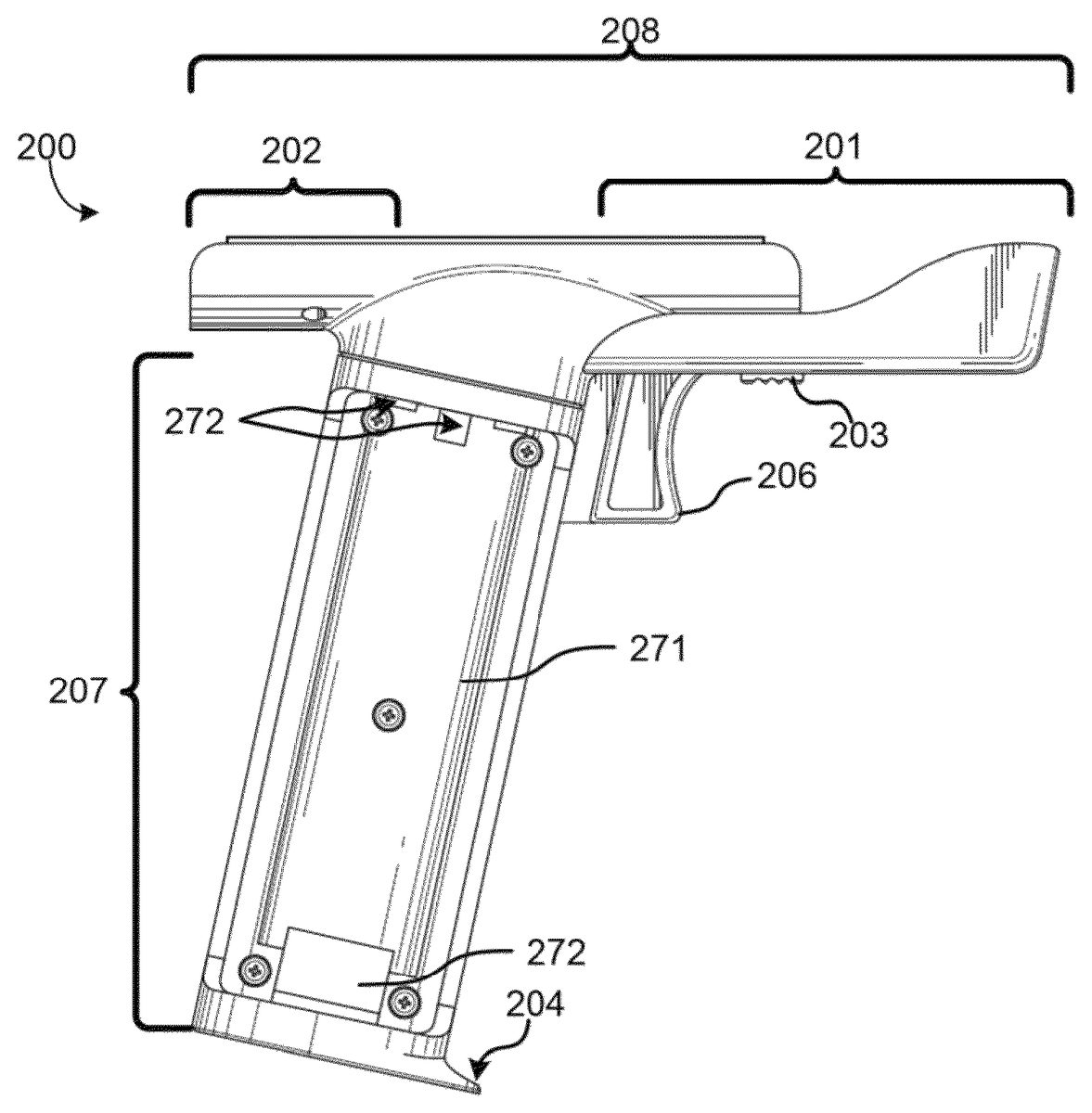
FIGS. 2A-2Eare diagrams illustrating an example controller attachment apparatus200in accordance with one embodiment of present invention. Referring now toFIG. 2A, a side view of the apparatus200is provided depicting a body208configured to receive a controller, a grip207attached to the body, a trigger206disposed where the grip207meets the body208and a controller release slider switch203located disposed on the body208. In whole, the apparatus200illustrated has shape substantially similar to a handheld firearm.FIGS. 2B and 2Cprovide additional front and bottoms views of the apparatus200.
As shown inFIGS. 2A-2C, the body208of the apparatus200is an elongated element with a front portion201resembling the barrel or the barrel support of a handheld firearm, and a back portion202resembling the section of a handheld firearm where the hammer is typically located. The trigger206extends from the body208and is positioned in front of the grip207of the apparatus200. Additionally, although not illustrated, for some embodiments a trigger guard may be positioned in front of the trigger to prevent unintentional actuation of the trigger, and to add to overall the realism of the apparatus200as being a firearm. The body208here is further equipped with a slide switch203that facilitates the release of a controller attached to the apparatus200, More with regard to releasing a controller will be described later with reference toFIGS. 2D and 2E.
As shown, the body208is configured to receive and retain a substantially rectangular-shaped controller that sits on top of the body208, such as a Wii® controller. From reading this description, one of ordinary skill in the art would appreciate and understand that other embodiments in accordance with the invention may be configured to attach to controllers having a form-factor different from those illustrated or described herein.
The grip207is shown to be extending from the body208at an angle common for handheld firearms, and has is configured with a socket portion271configured to receive, retain and store a controller's compartment panel. Typically, the panel stored by the socket271is that of the compartment to which the apparatus200attaches. In some embodiments, the grip207may be further configured with features commonly found on the grips equipped on handheld firearms. For example, the grip may have aesthetic features that give the grip a gun-like appearance, thereby adding to the realism of the apparatus. In the illustrated example, the grip is configured with a protrusion204that adds to the gun-like feel of the apparatus200.
For more detail regarding the body208, we now turn toFIGS. 2D and 2E, which respectively provide a top view and a perspective top view of apparatus200. As depicted, the top portion of body208depicted functions as a coupling mechanism and, in particular, is configured to attach to a controller by attaching to a compartment of a controller. As noted above, in some embodiments the coupling mechanism of the body208may be a cradle, cavity, bay, recess or cut-away configured to receive and hold a controller. One of ordinary skill in the art would appreciate that various embodiment may be equipped with alternative coupling mechanisms, which may vary in shape, without departing from the scope of the invention.
Continuing with reference toFIGS. 2D and 2E, the body208of apparatus200shown to be configured with a holding mechanism comprising clip features215and212. Although both clip features215and212are shaped such that each can mate with a corresponding structural feature of a controller's compartment, clip feature215is a static feature while clip feature212is a non-static feature, configured to be selectively displaced when a user wants to separate a controller from apparatus200. More with regard to clip feature212will be discussed later with respect toFIG. 3A. Although only clip features are depicted and described, it will be understood and appreciated by those of skill in the art that other means for holding a controller to the apparatus could be utilized in place of, or in addition to, the clip features without departing from the spirit of the present invention. For example, the body208could be configured with tab features that correspond to structural features of a controller, thereby assisting in securing the apparatus200to a controller. Further, though not shown, in other embodiments, the
Depending on the embodiment, the coupling mechanism of body208may be configured with a means for actuating a button or switch located in the compartment of a controller, thereby allowing a user to access a button or switch within the compartment that would otherwise be inaccessible once the apparatus200is attached to the controller. For example, a button means219may be disposed through the body208such that when a controller is attached to the apparatus, a user may actuate a button disposed within the controller's compartment without the need to detach the controller from the apparatus. Similarly, body208is also configured with a trigger means209that, once the apparatus200is attached to the controller, enables a user to actuate a trigger disposed on the controller. More with regard to trigger actuators is discussed with respect toFIG. 3B.
Referring now toFIG. 3A, the clip feature212is depicted in its selectively displaced orientation. In some embodiments, the clip feature212is controlled by the user using slider switch203. For example, when a user wants to release a controller form the apparatus200, the user would simply slide the slide switch203towards the rear of the apparatus200, thereby causing the clip feature212to move in the same direction backwards, as shown in view221. By doing so, the clip feature212detaches itself from those structure features of the controller utilized to secure the apparatus200to the controller.
In another example, an apparatus200may comprise a body208configured with tracks that cause a controller to attach to the apparatus when the controller is slid in a first direction with respect to the body (e.g.,208), and release from the apparatus when the controller is slid in a second (opposite) direction with respect to the body (e.g.,208). The body of this example apparatus may further comprise a locking mechanism that prevents the controller from sliding in the second direction with respect to the body once the controller is secured to the body by the sliding action in the first direction. For instance, a pin mechanism can be utilized to engage the controller once the controller is slid into place, and the pin mechanism may be controlled by the slider switch203. In alternative embodiments, the slider switch203may be replaced by other control mechanisms that can similarly control the release of the controller from the apparatus such as a button or a tab.
Similarly, with reference toFIG. 3b, trigger means209is depicted in its displaced position. In some embodiment, the trigger means209is controller by the user using the trigger206. In such embodiments, when the user wants to actuate the trigger of a controller attached to the apparatus, that user would simply pull back on the trigger causing the trigger means209to protrude, causing the trigger button on the underside of a controller to be actuated. View224provides a depiction of the trigger means209protruding.
FIG. 4is a diagram illustrating an exploded view of the controller attachment apparatus200, which provides a depiction of example implementations of the button means and trigger means. Specifically,FIG. 4shows the trigger means209, and how its attached to the trigger206; handle portion207comprising of a left half273and a right half270; and a clip feature212, which combines with slider switch203vis-à-vis component260to form a slider assembly263. Also illustrated is body208, comprising a cavity to contain trigger means209and slider assembly263; several openings (243,246, and249) for the various button actuating means (e.g., trigger means209, button means219); and a covering250having openings (256,253) that correspond to trigger means209and the slider assembly means263. Though the trigger means209is depicted a single piece that slides within the body when the trigger206is actuated, is should be understood by those of ordinary skill that the trigger means209may be implemented using multiple components that create a trigger means assembly. Additionally, although not shown, a resilient element, such as a spring, may be utilized in conjunction with the trigger means209or slider assembly263to assist a user in actuating the means causing them to slide).
In addition, the right half270of the handle207comprises a socket271configured to receive and retain a controller cover/panel280. In some embodiments, the cover/panel280received and retained by socket271is the cover/panel of the controller's compartment to which body208attaches. More with respect to cover/panel280is discussed with respect toFIGS. 5A-5D, which illustrate the use of the controller attachment apparatus200with an example game controller500.
Referring now toFIGS. 5A-5D, inFIG. 5Aa controller500is shown separated from its battery compartment panel280. Once separated, apparatus200attaches to the battery compartment of controller500and takes the place of panel280.FIG. 5Bshows how the controller500appears once it is successfully attached to apparatus200. It should be noted that although the illustrated embodiment depicts the apparatus200attached to the controller500at its battery compartment, one of ordinary skill in the art would understand and appreciate that other apparatuses in accordance with an embodiment of the invention can connect to other compartments on a controller and, optionally, have a socket on the handle configured to receive and retain the cover/panel of the compartment to which the apparatus attaches.
Continuing withFIG. 5C, the front and back of battery panel280is shown in greater detail. As depicted inFIG. 5D, the battery panel280, which is displaced by the attachment of apparatus200to the controller500, is attached to the handle vis-à-vis a properly configured socket.
FIG. 6is a diagram illustrating an example functional block diagram of a controller in accordance with one embodiment of the invention. Referring now toFIG. 6, the example controller includes a control module322, an input module326, a stimulus module328, and a biosensor module330. Also a communication interface module334is provided to enable communication between the controller attachment apparatus and other units, such as, the controller to which the controller attachment is attached or a gaming console. One or more biosensor modules330might be provided to receive data from the biological or physiological sensors and, either alone or in combination with control module322, convert those signals into appropriate data representations that can be properly interpreted by the game application or game driver to sense the biofeedback and operate on it accordingly. For example, a heart rate signal might be converted into an 8 bit PCM data stream that can be sent to the game application by way of communication interface module334.
Stimulus module328can be provided to provide the appropriate signals to drive electrodes or other contacts that might be installed on the controller attachment apparatus to provide the desired stimulus. For example, stimulus module328might be comprised for a TENS circuit driven by a game to provide the appropriate levels of current to the electrodes to provide the electro stimulus. Likewise, stimulus module328might be implemented as selectable drivers to provide the appropriate current in the desired polarity to Peltier devices to adjust the temperature that is experienced by the game while playing the game.
User input module326can also be implemented to include appropriate receivers, analog-to-digital converters to accept user input of buttons, joysticks and other switches that may be located on the controller attachment apparatus. Optionally, an auxiliary display module (not shown) may be included to implement the appropriate converters and drivers needed to provide a still or motion image signal to an optional auxiliary display that may be disposed on the controller attachment apparatus. An auxiliary display module might also be used to provide soft or hard menus and cursors to allow setup selection for game or controller operations locally to the controller. Thus, for example, the display module might be used to allow the gamer to reprogram or reconfigure the controller independently of a gaming application.
A control module322may be provided to control various operations of the controller. For example, a processor or processors system can be provided to control the various operations of controller.
As used herein, the term module is used to describe a given unit of functionality that can be performed in accordance with one or more embodiments of the present invention. As used herein, a module can be implemented utilizing any form of hardware, software, or a combination thereof. In implementation, the various modules described herein can be implemented as discrete modules or the functions and features described can be shared in part or in total among one or more modules. In other words, as would be apparent to one of ordinary skill in the art after reading this description, the various features and functionality described herein may be implemented in any given application can be implemented in one or more separate or shared modules in various combinations and permutations. Even though various features or elements of functionality may be individually described or claimed as separate modules, one of ordinary skill in the art will understand that these features and functionality can be shared among one or more common software and hardware elements, and such description shall not require or imply that separate hardware or software components are used to implement such features or functionality.
Although the invention is described above in terms of various exemplary embodiments and implementations, it should be understood that the various features, aspects and functionality described in one or more of the individual embodiments are not limited in their applicability to the particular embodiment with which they are described, but instead can be applied, alone or in various combinations, to one or more of the other embodiments of the invention, whether or not such embodiments are described and whether or not such features are presented as being a part of a described embodiment. Thus, the breadth and scope of the present invention should not be limited by any of the above-described exemplary embodiments.
Terms and phrases used in this document, and variations thereof, unless otherwise expressly stated, should be construed as open ended as opposed to limiting. As examples of the foregoing: the term “including” should be read as meaning “including, without limitation” or the like; the term “example” is used to provide exemplary instances of the item in discussion, not an exhaustive or limiting list thereof: the terms “a” or “an” should be read as meaning “at least one,” “one or more” or the like; and adjectives such as “conventional,” “traditional,” “normal,” “standard,” “known” and terms of similar meaning should not be construed as limiting the item described to a given time period or to an item available as of a given time, but instead should be read to encompass conventional, traditional, normal, or standard technologies that may be available or known now or at any time in the future. Likewise, where this document refers to technologies that would be apparent or known to one of ordinary skill in the art, such technologies encompass those apparent or known to the skilled artisan now or at any time in the future.
The presence of broadening words and phrases such as “one or more,” “at least,” “but not limited to” or other like phrases in some instances shall not be read to mean that the narrower case is intended or required in instances where such broadening phrases may be absent. The use of the term “module” does not imply that the components or functionality described or claimed as part of the module are all configured in a common package. Indeed, any or all of the various components of a module, whether control logic or other components, can be combined in a single package or separately maintained and can further be distributed in multiple groupings or packages or across multiple locations.
Claims
- A controller attachment apparatus configured to adapt a game controller having a battery compartment with a cover into a firearm-shaped game controller, the controller attachment apparatus comprising: a body;and a grip attached to and extending away from a rear section of the body;wherein the body comprises a cradle having a clip, the cradle configured to accept the game controller, the clip configured to selectively retain the game controller, and the cradle and clip further configured to attach to the game controller in place of the cover;and wherein the grip comprises a socket configured to accept and selectively retain the cover.
- The controller attachment apparatus of claim 1 , further comprising: a first trigger disposed on the grip near where the body attaches to the grip;and a means attached to the first trigger, the means configured to actuate a second trigger on the game controller when the first trigger is actuated.
- A controller attachment apparatus, comprising: a handle;and a coupling mechanism attached to the handle configured to accept a controller, the coupling mechanism designed to attach to a battery compartment with a panel of the controller and comprising a holding mechanism, the holding mechanism designed to selectively retain the battery compartment once the controller is attached to the coupling mechanism, wherein the coupling mechanism and holding mechanism are configured to attach to the battery compartment in place of the panel;wherein the coupling mechanism is designed to replace the panel of the compartment;and wherein the handle comprises a socket designed to accept and selectively retain the panel.
- The controller attachment apparatus of claim 3 , further comprising: a first button disposed on the handle;and a means for actuating a second button on the controller when the first button is actuated.
- The controller attachment apparatus of claim 4 , wherein the first button is a first trigger button.
- The controller attachment apparatus of claim 4 , wherein the second button is a second trigger button.
- The controller attachment apparatus of claim 3 , wherein the holding mechanism is designed to retain the compartment by way of structural features disposed within the compartment.
- The controller attachment apparatus of claim 3 , wherein the handle is oriented to the coupling mechanism such that when the controller is attached to the coupling mechanism, the controller attachment apparatus is shaped similar to a handheld firearm.
- The controller attachment apparatus of claim 3 , further comprising a biosensor module configured to sense a biological condition of a user of the controller attachment apparatus and to send an information representative of the biological condition to the controller via a communication interface.
- The controller attachment apparatus of claim 9 , wherein the biosensor module comprises a moisture sensor.
- The controller attachment apparatus of claim 9 , wherein the biosensor module comprises a plurality of electrodes disposed on the handle.
- The controller attachment apparatus of claim 9 , wherein the representative biological information comprises a heart rate or a temperature of the user of the game controller.
- The controller attachment apparatus of claim 9 , wherein the representative biological information comprises an amount of pressure the user of the game controller is exerting on the biosensor module.
- The controller attachment apparatus of claim 3 , further comprising a stimulus module configured to receive an instruction from the controller and to apply a sensory feedback to the user of the controller attachment apparatus.
- The controller attachment apparatus of claim 14 , wherein the sensory feedback is an electric shock or a change of temperature.
- The controller attachment apparatus of claim 14 , wherein the sensory feedback causes the controller attachment apparatus to recoil.
- The controller attachment apparatus of claim 3 , wherein the holding mechanism comprises a switch configured to selectively release the controller after the controller has been selectively retained by the holding mechanism.
- The controller attachment apparatus of claim 3 , wherein the coupling mechanism further comprises: a first button disposed on the coupling mechanism;and a means for actuating a second button within the compartment of the controller when the coupling, mechanism is attached to the compartment of the controller and the first button is actuated.
Disclaimer: Data collected from the USPTO and may be malformed, incomplete, and/or otherwise inaccurate.