U.S. Pat. No. 8,740,700
GAME SYSTEM, GAME PROCESSING METHOD, GAME APPARATUS, HANDHELD GAMING DEVICE, AND STORAGE MEDIUM
AssigneeNintendo Co Ltd
Issue DateJanuary 18, 2012
Illustrative Figure
Abstract
An object control section individually moves, in a virtual space, a plurality of first objects each associated to a direction input section among a plurality of direction input sections disposed on a first operating device, in accordance with directions inputted through the associated direction input sections. A virtual camera control section controls a first virtual camera in the virtual space. A game image generation section generates a first game image based on the first virtual camera. The virtual camera control section rotates the first virtual camera in accordance with the positions of the plurality of the first objects in the virtual space, such that a certain one of the first objects first game image is displayed on a predetermined side with regard to a displayed position of another one of the first objects.
Description
DETAILED DESCRIPTION OF NON-LIMITING EXAMPLE EMBODIMENTS A game system according to one embodiment will be described with reference toFIG. 1. As shown inFIG. 1, a game system1includes a household television receiver (hereinafter, referred to as a monitor)2, and a stationary game apparatus3connected to the monitor2via a connection cord. The monitor2includes loudspeakers2a. Furthermore, the game apparatus3includes an optical disc4, a game apparatus body5, a terminal device6, and controllers7a,7b,7c, and7d(hereinafter, described simply as a controller7when there is no particular need to distinguish these as the controllers7a,7b,7c, and7d). The optical disc4has stored therein an information processing program (typically, a game program) to be executed by the game apparatus body5. The monitor2displays a game image outputted from the game apparatus body5. The monitor2includes the loudspeakers2a, and each of the loudspeakers2aoutputs a game sound outputted from the game apparatus body5. The game apparatus body5executes a game process or the like based on a game program stored in the optical disc4. A plurality of operation sections (operation buttons) are provided on the controller7. The controller7transmits, to the game apparatus body5, operation data (controller operation data) representing input states (whether or not each of the operation buttons has been held down) of the operation sections by using, for example, Bluetooth (registered trademark) technology. Furthermore, the controller7includes an imaging section for taking images of a marker8having two LED modules (hereinafter, referred to as “markers”)8L and8R disposed in the vicinity (in the upper side of the screen inFIG. 1) of the display screen of the monitor2, and an imaging information calculation section for calculating positions of the markers within an image taken by the imaging section. The positions of the markers calculated by the imaging information calculation section are transmitted to the game apparatus body5as marker coordinate data. In the game apparatus body5, the movement, position, attitude, and the ...
DETAILED DESCRIPTION OF NON-LIMITING EXAMPLE EMBODIMENTS
A game system according to one embodiment will be described with reference toFIG. 1.
As shown inFIG. 1, a game system1includes a household television receiver (hereinafter, referred to as a monitor)2, and a stationary game apparatus3connected to the monitor2via a connection cord. The monitor2includes loudspeakers2a. Furthermore, the game apparatus3includes an optical disc4, a game apparatus body5, a terminal device6, and controllers7a,7b,7c, and7d(hereinafter, described simply as a controller7when there is no particular need to distinguish these as the controllers7a,7b,7c, and7d).
The optical disc4has stored therein an information processing program (typically, a game program) to be executed by the game apparatus body5.
The monitor2displays a game image outputted from the game apparatus body5. The monitor2includes the loudspeakers2a, and each of the loudspeakers2aoutputs a game sound outputted from the game apparatus body5.
The game apparatus body5executes a game process or the like based on a game program stored in the optical disc4.
A plurality of operation sections (operation buttons) are provided on the controller7. The controller7transmits, to the game apparatus body5, operation data (controller operation data) representing input states (whether or not each of the operation buttons has been held down) of the operation sections by using, for example, Bluetooth (registered trademark) technology.
Furthermore, the controller7includes an imaging section for taking images of a marker8having two LED modules (hereinafter, referred to as “markers”)8L and8R disposed in the vicinity (in the upper side of the screen inFIG. 1) of the display screen of the monitor2, and an imaging information calculation section for calculating positions of the markers within an image taken by the imaging section. The positions of the markers calculated by the imaging information calculation section are transmitted to the game apparatus body5as marker coordinate data. In the game apparatus body5, the movement, position, attitude, and the like can be calculated by the controller7based on the marker coordinate data.
Furthermore, the controller7is provided with an acceleration sensor and a gyro sensor. Acceleration data representing acceleration detected by the acceleration sensor and angular velocity data representing angular velocity detected by the gyro sensor are transmitted to the game apparatus body5. In the game apparatus body5, directions, movements, and behaviors of the controller7can be calculated based on the acceleration data and/or the angular velocity data.
The terminal device6is a portable device that is small enough to be held by a user, and the user is allowed to move the terminal device6with hands, or place the terminal device6at any location. Although the specific structure of the terminal device6will be described later, the terminal device6includes an LCD (Liquid Crystal Display)61as display means, and input means (a touch panel62, a gyro sensor604, and the like described later). The terminal device6and the game apparatus body5are communicable with each other wirelessly or via a cable. The terminal device6receives, from the game apparatus body5, data of an image (e.g., a game image) generated in the game apparatus body5, and displays the image represented by the data on an LCD61. Although in the exemplary embodiment, an LCD is used as a display device, the terminal device6may include any other display device, such as a display device utilizing EL (Electro Luminescence), for example. Further, the terminal device6transmits, to the game apparatus body5, operation data representing the content of an operation performed on the terminal device6.
Next, with reference toFIG. 2, an internal structure of the game apparatus body5will be described.FIG. 2is a block diagram illustrating an example of an internal structure of the game apparatus body5. The game apparatus body5includes a CPU (Central Processing Unit)10, a system LSI (Large Scale Integration)11, an external main memory12, a ROM/RTC (Read Only Memory/Real Time Clock)13, a disc drive14, an AV-IC (Audio Video-Integrated Circuit)15and the like.
In addition to the CPU10, the external main memory12, the ROM/RTC13, the disc drive14, and the AV-IC15are connected to the system LSI11. The external main memory12, which is a volatile memory, is used as a work region and a buffer region for the CPU10. The ROM/RTC13includes a ROM (so-called boot ROM) incorporating a program for booting the game apparatus body5, and a clock circuit (RTC) for counting time. The disc drive14reads, from the optical disc4, program data, texture data and the like, and writes the read data into an internal main memory35described below or the external main memory12.
The system LSI11includes an input/output processor (I/O processor)31, a GPU (Graphics Processor Unit)32, a DSP (Digital Signal Processor)33, a VRAM (Video RAM)34, and the internal main memory35.
The GPU32generates an image in accordance with a graphics command (draw command) supplied from the CPU10. In the exemplary embodiment, the game apparatus body5may generate both a game image to be displayed on the monitor2and a game image to be displayed on the terminal device6. Hereinafter, the game image to be displayed on the monitor2may be referred to as a “monitor game image,” and the game image to be displayed on the terminal device6may be referred to as a “terminal game image.”
The DSP33, serving as an audio processor, generates sound data by using sound data and sound waveform (tone quality) data stored in the internal main memory35and the external main memory12. In the exemplary embodiment, similarly to the game images, both a game sound to be outputted from the loudspeakers2aof the monitor2and a game sound to be outputted from the loudspeakers of the terminal device6may be generated. Hereinafter, the game sound to be outputted from the monitor2may be referred to as a “monitor game sound,” and the game sound to be outputted from the terminal device6may be referred to as a “terminal game sound.”
Among the image data and sound data generated by the game apparatus body5, the image data and sound data to be outputted to the monitor2are read by the AV-IC15. Through an AV connector16, the AV-IC15outputs the read image data to the monitor2and outputs the read sound data to the loudspeakers2aincluded in the monitor2. Thereby, an image is displayed on the monitor2, and sounds are outputted from the loudspeakers2a.
Further, among the image data and sound data generated by the game apparatus body5, the image data and sound data to be outputted to the terminal device6are transmitted to the terminal device6by the I/O processor31or the like. Data transmission to the terminal device6by the I/O processor31or the like will be described later.
The I/O processor31executes data reception and transmission with the components connected thereto, and download of data from an external apparatus. The I/O processor31is connected to a flash memory17, a network communication module18, a controller communication module19, an extension connector20, a memory card connector21, and a codec LSI27. The codec LSI27is connected to a terminal communication module28.
The game apparatus body5is connected to a network such as the Internet so as to communicate with external information processing apparatuses (for example, other game apparatuses or various servers). That is, the I/O processor31is connected to a network via the network communication module18and the antenna22so as to communicate with external information processing apparatuses connected to the network. The flash memory17may store not only the data transmitted and received between the game apparatus body5and the external information processing apparatuses, but also saved data (result data or progress data of the process) of the game played with the game apparatus body5. Further, the flash memory17may store programs such as a game program.
The game apparatus body5can receive operation data from the controller7. That is, the I/O processor31receives, via the antenna23and the controller communication module19, operation data or the like transmitted from the controller7, and stores (temporarily) the data in a buffer region of the internal main memory35or the external main memory12.
The game apparatus body5is capable of transmitting/receiving image data, sound data and the like to/from the terminal device6. The I/O processor31outputs data of a game image (terminal game image) generated by the GPU32to the codec LSI27. The codec LSI27performs a predetermined compression process on the image data supplied from the I/O processor31. The terminal communication module28performs wireless communication with the terminal device6. Accordingly, the image data compressed by the codec LSI27is transmitted by the terminal communication module28to the terminal device6via an antenna29. In the exemplary embodiment, the codec LSI27compresses the image data by using a highly efficient compression technique, for example, the H.264 standard. The codec LSI27may adopt other compression techniques. When the communication rate is sufficiently high, uncompressed image data may be transmitted. The terminal communication module28is, for example, a Wi-Fi certified communication module. The terminal communication module28may perform wireless communication with the terminal device6at a high speed by using, for example, the technique of MIMO (Multiple Input Multiple Output) adopted in the IEEE802.11n standard, or may use other communication techniques.
The game apparatus body5transmits, to the terminal device6, sound data as well as the image data. That is, the I/O processor31outputs sound data (terminal game sound) generated by the DSP33to the terminal communication module28via the codec LSI27. The codec LSI27performs a compression process on the sound data in a manner similar to that for the image data. Any compression technique may be adopted for the sound data. In another embodiment, uncompressed sound data may be transmitted. The terminal communication module28transmits the compressed image data and sound data to the terminal device6via the antenna29.
The game apparatus body5transmits, in addition to the image data and sound data, various control data to the terminal device6, according to need. The control data represent control instructions for the components included in the terminal device6, such as an instruction to control on/off of a marker section (a marker section65shown inFIG. 5), and an instruction to control image taking of a camera (a camera66shown inFIG. 5). The I/O processor31transmits the control data to the terminal device6in response to an instruction from the CPU10.
The game apparatus body5can receive various data from the terminal device6. Although details will be described later, in the exemplary embodiment, the terminal device6transmits operation data, image data, and sound data. The respective data transmitted from the terminal device6are received by the terminal communication module28via the antenna29. The image data and sound data transmitted from the terminal device6have been subjected to a compression process similar to that for the image data and sound data transmitted from the game apparatus body5to the terminal device6. Accordingly, these image data and sound data are transmitted from the terminal communication module28to the codec LSI27, and subjected to a decompression process by the codec LSI27. The decompressed data are outputted to the I/O processor31. The operation data, which has been received by the terminal communication module28, is outputted to the I/O processor31via the codec LSI27. The I/O processor31stores (temporarily) the data received from the terminal device6in the buffer region of the internal main memory35or the external main memory12.
The game apparatus body5is connectable to other devices and external storage media via the extension connector20and the memory card connector21.
The game apparatus body5includes (on the front main surface thereof, for example) a power button24, a reset button25, an insertion slot through which the optical disc4is inserted, an eject button26for ejecting the optical disc4from the insertion slot of the game apparatus body5, and the like.
In another embodiment, some of the components of the game apparatus body5may be constituted as an extension device separated from the game apparatus body5. At this time, the extension device may be connected to the game apparatus body5via the extension connector20, for example. Specifically, the extension device may include, for example, the codec LSI27, the terminal communication module28, and the antenna29, and may be detachably connected to the extension connector20. Thus, by connecting the extension device to the game apparatus body which does not have the above-mentioned, the game apparatus body can be made communicable with the terminal device6.
Next, a structure of the terminal device6will be described with reference toFIG. 3toFIG. 5.FIG. 3is a diagram illustrating an example of an external structure of the terminal device6. More specifically, (a) ofFIG. 3is a front view, (b) ofFIG. 3is a top view, (c) ofFIG. 3is a right side view, and (d) ofFIG. 3is a bottom view of the terminal device6.FIG. 4shows an example of a state in which a user holds the terminal device6with both hands.
As shown inFIG. 3, the terminal device6includes a housing60which generally has a horizontally long plate-like rectangular shape. The housing60is small enough to be held by the user.
The terminal device6includes the LCD61on a front surface of the housing60. The LCD61is provided near the center of the front surface of the housing60. Therefore, as shown inFIG. 4, the user, holding the housing60at portions to the right and left of the LCD61, is allowed to move the terminal device6while viewing a screen of the LCD61.
As shown in (a) ofFIG. 3, the terminal device6includes, as operation means, a touch panel62on the screen of the LCD61. In the exemplary embodiment, the touch panel62is, but is not limited to, a resistive film type touch panel, and a touch panel of any type, such as electrostatic capacitance type, may be used. The touch panel62may be of single touch type or multiple touch type. In the exemplary embodiment, the touch panel62has the same resolution (detection accuracy) as that of the LCD61. However, the resolution of the touch panel62and the resolution of the LCD61need not be the same. Since the terminal device6has the touch panel62, the user is allowed to operate the touch panel62while moving the terminal device6. That is, the user is allowed to directly (by using the touch panel62) perform an input onto the screen of the LCD61while moving the LCD61.
As shown inFIG. 3, the terminal device6has, as operation means, two analog sticks63A and63B, and a plurality of operation buttons64A to64L. The analog sticks63A and63B are each a device for designating a direction. The analog sticks63A and63B are each configured such that a stick part thereof to be operated by a finger of the user is slidable or tiltable in any direction (at any angle in any direction such as the upward, the downward, the rightward, the leftward, or the diagonal direction) with respect to the front surface of the housing60.
The respective operation buttons64A to64L are assigned functions, according to need, in accordance with a game program. For example, the cross button64A may be used for direction designation operation, selection operation, and the like; and the operation buttons64E to64H may be used for determination operation, cancellation operation, and the like.
As shown in (a) ofFIG. 3, the terminal device6includes a marker section (the marker section65shown inFIG. 5) including a marker65A and a marker65B, on the front surface of the housing60. The markers65A and65B are each constituted by one or more infrared LEDs. The marker section65is used, like the marker8, for causing the game apparatus body5to calculate a movement or the like of the controller7with respect to the marker section65. The game apparatus body5is capable of controlling the infrared LEDs of the marker section65to be turned on or off.
The terminal device6includes the camera66. The camera66is disposed on the surface of the housing60. Accordingly, the camera66is capable of taking an image of the face of the user holding the terminal device6. For example, the camera66can take an image of the user who is playing a game while viewing the LCD61.
The terminal device6has a microphone (a microphone609shown inFIG. 5) as sound input means. The microphone609is embedded in the housing60at a position inside the microphone hole60b. The microphone609detects for a sound, such as user's voice, around the terminal device6.
The terminal device6has loudspeakers (loudspeakers607shown inFIG. 5). Sound from the loudspeakers607is outputted from loudspeaker holes60aprovided on the lower side surface of the housing60.
The terminal device6includes an extension connector67for connecting other devices to the terminal device6.
In the terminal device6shown inFIG. 3, the shapes of the operation buttons and the housing60, the number of the respective components, and the positions in which the components are provided are merely examples. The shapes, numbers, and positions may be different from those described above.
Next, an internal structure of the terminal device6will be described with reference toFIG. 5.FIG. 5is a block diagram illustrating an example of an internal structure of the terminal device6. As shown inFIG. 5, the terminal device6includes, in addition to the components shown inFIG. 3, a touch panel controller601, a magnetic sensor602, an acceleration sensor603, the gyro sensor604, a user interface controller (UI controller)605, a codec LSI606, loudspeakers607, a sound IC608, a microphone609, a wireless module610, an antenna611, an infrared communication module612, a flash memory613, a power supply IC614, a battery615, and a vibrator619. These electronic components are mounted on an electronic circuit board and accommodated in the housing60.
The UI controller605is a circuit for controlling data input to various input/output sections and data output from various input/output sections. The UI controller605is connected to the touch panel controller601, an analog stick63(the analog sticks63A and63B), the operation button64(the operation buttons64A to64L), the marker section65, the magnetic sensor602, the acceleration sensor603, the gyro sensor604, and the vibrator619. Further, the UI controller605is connected to the codec LSI606and the extension connector67. The power supply IC614is connected to the UI controller605, so that power is supplied to the respective components through the UI controller605. The internal battery615is connected to the power supply IC614, so that power is supplied from the battery615. Further, a battery charger616or a cable, which is supplied with power from an external power supply, may be connected to the power supply IC614via a connector or the like. In this case, the terminal device6can be supplied with power and charged from the external power supply by using the battery charger616or the cable.
The touch panel controller601is a circuit which is connected to the touch panel62and controls the touch panel62. The touch panel controller601generates a predetermined form of touch position data, based on a signal from the touch panel62, and outputs the touch position data to the UI controller605. The touch position data represents coordinates of a position at which an input is performed on an input surface of the touch panel62. The touch panel controller601reads a signal from the touch panel62and generates touch position data every predetermined period of time. Further, various control instructions are outputted from the UI controller605to the touch panel controller601.
The analog stick63outputs, to the UI controller605, stick data representing an amount and direction of the sliding (or tilting) of the stick part. The operation button64outputs, to the UI controller605, operation button data representing an input status of each of the operation buttons64A to64L (whether or not the operation button is pressed).
The magnetic sensor602detects the magnitude and direction of a magnetic field to detect an orientation. Orientation data representing the detected orientation is outputted to the UI controller605. The UI controller605outputs, to the magnetic sensor602, a control instruction for the magnetic sensor602. Examples of the magnetic sensor602include: an MI (Magnetic Impedance) sensor, a fluxgate sensor, a Hall sensor, a GMR (Giant Magneto Resistance) sensor, a TMR (Tunneling Magneto Resistance) sensor, and an AMR (Anisotropic Magneto Resistance) sensor. However, any sensor may be adopted as long as the sensor can detect an orientation.
The acceleration sensor603is provided inside the housing60. The acceleration sensor603detects the magnitudes of linear accelerations in all three axial directions (xyz axial directions shown in (a) ofFIG. 3). Acceleration data representing the detected accelerations is outputted to the UI controller605. The UI controller605outputs, to the acceleration sensor603, a control instruction for the acceleration sensor603.
The gyro sensor604is provided inside the housing60. The gyro sensor604detects the angular velocities around all the three axes (the above-described xyz axes). Angular velocity data representing the detected angular velocities is outputted to the UI controller605. The UI controller605outputs, to the gyro sensor604, a control instruction for the gyro sensor604.
The vibrator619is, for example, a vibration motor or a solenoid, and the terminal device6is vibrated by actuating the vibrator619in accordance with a control instruction outputted from the UI controller605to the vibrator619.
The UI controller605outputs, to the codec LSI606, the operation data (hereinafter, referred to as terminal operation data) including the touch position data, the stick data, the operation button data, the orientation data, the acceleration data and the angular velocity data, which have been received from the respective components.
The codec LSI606is a circuit for performing a compression process on data to be transmitted to the game apparatus body5, and a decompression process on data transmitted from the game apparatus body5. The LCD61, the camera66, the sound IC608, the wireless module610, the flash memory613, and the infrared communication module612are connected to the codec LSI606. The codec LSI606includes a CPU617and an internal memory618. Although the terminal device6is configured not to perform a game process, the terminal device6may execute a program for managing the terminal device6or a program for communication. For example, a program stored in the flash memory613is loaded into the internal memory618and executed by the CPU617when the terminal device6is powered on, thereby starting up the terminal device6. A part of the area of the internal memory618is used as a VRAM for the LCD61.
The camera66takes an image in accordance with an instruction from the game apparatus body5, and outputs data of the taken image to the codec LSI606. The codec LSI606outputs, to the camera66, a control instruction for the camera66, such as an instruction to take an image. The camera66is also capable of taking a moving picture. That is, the camera66is capable of repeatedly performing image taking, and repeatedly outputting image data to the codec LSI606.
The sound IC608is a circuit for controlling input of sound data to the microphone609and output of sound data from the loudspeakers607.
The codec LSI606transmits the image data from the camera66, the sound data from the microphone609, and the terminal operation data from the UI controller605to the game apparatus body5via the wireless module610. In the exemplary embodiment, the codec LSI606subjects the image data and the sound data to a compression process similar to that performed by the codec LSI27. The compressed image data and sound data, and the terminal operation data are outputted to the wireless module610as transmission data. The antenna611is connected to the wireless module610, and the wireless module610transmits the transmission data to the game apparatus body5through the antenna611. The wireless module610has the same function as the terminal communication module28of the game apparatus body5. That is, the wireless module610has a function of connecting to a wireless LAN by a method based on, for example, the IEEE802.11n standard.
As described above, the transmission data transmitted from the terminal device6to the game apparatus body5includes the terminal operation data, the image data, and the sound data. If another device is connected to the terminal device6through the extension connector67, data received from the other device may be included in the transmission data. The infrared communication module612performs, with another device, infrared communication based on, for example, the IRDA standard. The codec LSI606may include, in the transmission data, data received by the infrared communication, and transmit the transmission data to the game apparatus body5, according to need.
As described above, the compressed image data and sound data are transmitted from the game apparatus body5to the terminal device6. These data are received by the codec LSI606through the antenna611and the wireless module610. The codec LSI606decompresses the received image data and sound data. The decompressed image data is outputted to the LCD61, and an image according to the image data is displayed on the LCD61. On the other hand, the decompressed sound data is outputted to the sound IC608, and a sound based on the sound data is outputted from the loudspeakers607.
When control data is included in the data received from the game apparatus body5, the codec LSI606and the UI controller605provide control instructions for the respective components, according to the control data. As described above, the control data represents control instructions for the respective components (in the exemplary embodiment, the camera66, the touch panel controller601, the marker section65, the sensors602to604, the vibrator619, and the infrared communication module612) included in the terminal device6. In the exemplary embodiment, the control instructions represented by the control data are considered to be instructions to start and halt (stop) the operations of the above-mentioned components. That is, some components which are not used for a game may be halted to reduce power consumption. In this case, data from the halted components are not included in the transmission data transmitted from the terminal device6to the game apparatus body5.
Next, a general outline of a game process executed by the game system1of the exemplary embodiment will be described with reference toFIG. 6toFIG. 12.
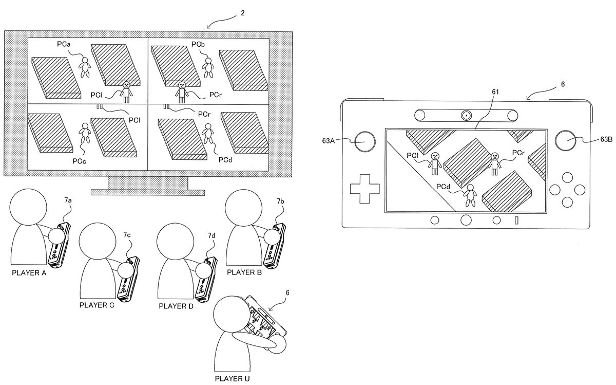
With the game system1, a plurality of players can play a game together by using the terminal device6and the controllers7a,7b,7c, and7d(as seen inFIG. 8). Here, a case will be described in which a game is played together by five players: player A, player B, player C, player D, and player U.
FIG. 6shows an appearance of a virtual space used in the game. Arranged on a game field in the virtual space are six player characters PCa, PCb, PCc, PCd, PCl, and PCr, and a plurality of obstacles. In addition, fruits, which are not shown, are also arranged on the game field.
The player characters PCa, PCb, PCc, and PCd are associated to the controllers7a,7b,7c, and7d, respectively. Here, the player A moves the player character PCa by operating a cross button disposed on a controller7a; the player B moves the player character PCb by operating a cross button disposed on a controller7b; the player C moves the player character PCc by operating a cross button disposed on a controller7c; and the player D moves the player character PCd by operating a cross button disposed on a controller7d.
The player character PCl is associated to the analog stick63A of the terminal device6, and the player character PCr is associated to the analog stick63B of the terminal device6. In this case, the player U moves the two player characters PCl and PCr by operating two direction input sections (the analog sticks63A and63B) disposed on the terminal device6.
An objective for the players A to D is to collect a prescribed number of fruits (not shown) arranged on the game field by moving the player characters PCa, PCb, PCc, and PCd. An objective for the player U is to move the player characters PCl and PCr to catch the other player characters PCa, PCb, PCc, and PCd for three times or more. Therefore, if the players A to D collect the prescribed number of the fruits, it is a victory for the players A to D; and if the player U catches the player characters PCa, PCb, PCc, and PCd for three times or more before the players A to D collect the prescribed number of the fruits, it is a victory for the player U.
It should be noted that movement velocities of the player characters PCl and PCr and the player characters PCa, PCb, PCc, and PCd are configured to be about the same. Therefore, if only either one of the player characters PCl and PCr were to chase the player character PCa, PCb, PCc, or PCd, it is difficult to catch the player character PCa, PCb, PCc, or PCd, and a long time will be required. However, it is possible to efficiently catch the player character PCa, PCb, PCc, or PCd by simultaneously moving the two player characters PCl and PCr so as to perform a pincer approach on the player character PCa, PCb, PCc, or PCd by using the two player characters PCl and PCr.
FIG. 7shows a game image (terminal game image) displayed on the LCD61of the terminal device6when the player characters PCa, PCb, PCc, PCd, PCl, and PCr are located at positions shown inFIG. 6. The player characters PCl and PCr are displayed in the terminal game image such that the halfway point between the player characters PCl and PCr is located almost at the center of the screen. Furthermore, in the terminal game image, the player character PCl is displayed on the left side with regard to a displayed position of the player character PCr (in other words, the player character PCr is displayed on the right side with regard to a displayed position of the player character PCl). The player U moves the player characters PCl and PCr by operating the analog sticks63A and63B while looking at the terminal game image.
As previously described, the player character PCl is associated to the analog stick63A, and the player character PCr is associated to the analog stick63B. Therefore, as a result of having the player character PCl displayed on the left side with regard to the displayed position of the player character PCr in the terminal game image, the player U can easily and intuitively understand respective associative relationships between the analog sticks63A,63B and the player characters PCl, PCr.
FIG. 8shows a game image (monitor game image) displayed on the monitor2when the player characters PCa, PCb, PCc, PCd, PCl, and PCr are located at positions shown inFIG. 6. In the exemplary embodiment, the monitor game image consists of four sub images for the players A to D. A sub image for the player A is displayed on the upper left area of the screen, a sub image for the player B is displayed on the upper right area of the screen, a sub image for the player C is displayed on the lower left area of the screen, and a sub image for the player D is displayed on the lower right area of the screen. The respective player characters PCa, PCb, PCc, and PCd are displayed at almost at the centers of the respective sub images.
When the game advances from the point in time inFIG. 6and when the player characters PCa, PCb, PCc, PCd, PCl, and PCr move to positions shown inFIG. 9, a terminal game image as shown inFIG. 10is displayed on the LCD61of the terminal device6. Also inFIG. 10, the player characters PCl and PCr are displayed in the terminal game image such that the halfway point between the player characters PCl and PCr is located almost at the center of the screen. Furthermore, in the terminal game image, the player character PCl is displayed on the left side with regard to the displayed position of the player character PCr. Such manner of displaying is achieved by rotating the virtual camera in accordance with the movements of the player characters PCl and PCr. A method for controlling the virtual camera will be described in detail later.
When the game advances from the point in time inFIG. 9and when the player characters PCa, PCb, PCc, PCd, PCl, and PCr move to positions shown inFIG. 11, a terminal game image as shown inFIG. 12is displayed on the LCD61of the terminal device6. Also inFIG. 12, the player characters PCl and PCr are displayed in terminal game image such that the halfway point between the player characters PCl and PCr is located almost at the center of the screen. Furthermore, in the terminal game image, the player character PCl is displayed on the left side with regard to the displayed position of the player character PCr.
As described above, in the exemplary embodiment, the player character PCl is displayed in the terminal game image on the left side with regard to the displayed position of the player character PCr regardless of the positions of the player characters PCl and PCr, through a rotation of the virtual camera in accordance with the movements of the player characters PCl and PCr. Therefore, no matter where the player characters PCl and PCr move, the player character PCl associated with the analog stick63A disposed on the left side of the LCD61is displayed at a position closer to the left end of the screen, and the player character PCr associated with the analog stick63B disposed on the right side of the LCD61is displayed at a position closer to the right end of the screen. Therefore, the player U can easily and intuitively understand the respective associative relationships between the analog sticks63A,63B and the player characters PCl, PCr, no matter where the player characters PCl and PCr move.
As a comparative example for describing the advantageous effect of the exemplary embodiment,FIG. 13shows a terminal game image in a case where the virtual camera is not rotated in a situation corresponding to that inFIG. 11. In the terminal game image inFIG. 13, the player character PCl associated to the analog stick63A disposed on the left side of the LCD61is displayed at a position closer to the right end of the screen, and the player character PCr associated with the analog stick63B disposed on the right side of the LCD61is displayed at a position closer to the left end of the screen. Therefore, the player U cannot intuitively understand the respective associative relationships between the analog sticks63A,63B and the player characters PCl, PCr; and thereby it becomes difficult to move the player characters PCl and PCr to desired locations. On the other hand, according to the exemplary embodiment, operability can be improved through a rotation of the virtual camera in accordance with the movements of the player characters PCl and PCr.
Next, detailed action of the game system1to achieve the game will be described with reference toFIG. 14toFIG. 19.
FIG. 14shows examples of various data stored in the external main memory12of the game apparatus body5when the game is executed.
A game program D1is a program that causes the CPU10of the game apparatus body5to execute a game process for achieving the game. The game program D1is loaded, for example, from the optical disc4to the external main memory12.
Game field data D2is data representing the game field, and patterns and shapes of obstacles arranged on the game field.
Player character data D3is data related to the play characters PCa, PCb, PCc, PCd, PCl, and PCr, and is data representing a shape, pattern, position, attitude, and the like of each of the player characters.
Virtual camera data D4is data related to virtual cameras (a virtual camera VC1for generating the terminal game image, and virtual cameras VC2a, VC2b, VC2c, and VC2dfor generating four sub images consisting the monitor game image) used for generating the game image. The camera data D4is data representing a position, attitude, angle of view, and the like of each of the virtual cameras. It should be noted that, as it will be described later, the positions and attitudes of the virtual cameras may be represented by, for example, a coordinate value of a gazing point P, an azimuth angle θ, an elevation/depression angle φ, and a camera distance d (FIG. 17).
Operation data D5is operation data that is periodically transmitted from each of the terminal device6and the controllers7a,7b,7c, and7d.
Next, with reference to flowcharts inFIG. 15andFIG. 16, a flow of the game process executed based on the game program D1by the CPU10of the game apparatus body5will be described.
When execution of the game program D1is initiated, first, at step S10inFIG. 15, the CPU10configures initial settings. In the initial settings, a process for arranging the player characters PCa, PCb, PCc, PCd, PCl, and PCr to initial positions in the virtual space, and the like are conducted.
At step S11, the CPU10acquires the operation data D5from the terminal device6and the controllers7a,7b,7c, and7d.
At step S12, the CPU10updates the positions of the player characters PCa, PCb, PCc, PCd, PCl, and PCr in the virtual space based on the operation data D5(i.e., updates the player character data D3). Specifically, the CPU10moves the player character PCl in a direction in accordance with a direction inputted through the analog stick63A of the terminal device6. For example, when the stick part of the analog stick63A is slid or tilted in the rightward direction, the player character PCl is moved on the game field so as to head toward the rightward direction on the screen. Similarly, the CPU10moves the player character PCr in a direction in accordance with a direction inputted through the analog stick63B of the terminal device6. Furthermore, the CPU10moves the player character PCa in a direction in accordance with a direction inputted through a cross button of the controller7a, moves the player character PCb in a direction in accordance with a direction inputted through a cross button of the controller7b, moves the player character PCc in a direction in accordance with a direction inputted through a cross button of controller7c, and moves the player character PCd in a direction in accordance with a direction inputted through a cross button of controller7d.
At step S13, the CPU10performs a virtual camera VC1control process. The virtual camera VC1control process is a process for determining the position and attitude of the virtual camera VC1in order to generate a terminal game image (i.e., updating the virtual camera data D4). In the following, details of the virtual camera VC1control process will be described with reference to the flowchart inFIG. 16. In the exemplary embodiment, the position and attitude of the virtual camera VC1are determined by calculating the coordinate value of the gazing point P, the azimuth angle θ, the elevation/depression angle φ, and the camera distance d as shown inFIG. 17.
At step S20inFIG. 16, the CPU10calculates the coordinate value of the gazing point P. The gazing point P is preferably set at a halfway point between the position of the player character PCl and the position of the player character PCr.
At step S21, the CPU10calculates the camera distance d. The camera distance d is a distance from the virtual camera to the gazing point P. In order to have both the player characters PCl and PCr displayed on the screen even when the player characters PCl and PCr become distant from each other, the camera distance d is preferably set to be a value that becomes larger as the distance (a character distance D described later) between the player characters PCl and PCr becomes larger. As another technique for having both the player characters PCl and PCr displayed on the screen even when the player characters PCl and PCr become distant from each other, the angle of view of the virtual camera may be widened as the distance between the player characters PCl and PCr becomes larger.
At step S22, the CPU10calculates the elevation/depression angle φ. The elevation/depression angle φ is an angle between a line-of-sight direction of the virtual camera (i.e., a straight line connecting the virtual camera and the gazing point) and an XY plane (i.e., a horizontal plane in a virtual world, or a game field). The elevation/depression angle φ is set, for example, at a value larger than 0° but smaller than 90°, and is preferably set at a value that becomes larger as the distance (the character distance D) between the player characters PCl and PCr becomes larger.
At step S23, the CPU10determines whether or not the player characters PCl and PCr are being simultaneously operated. Specifically, the CPU10refers to operation data of the terminal device6included in the operation data D5, and determines that the player characters PCl and PCr are simultaneously being operated if directions are inputted from both of the analog sticks63A and63B, and determines that the player characters PCl and PCr are not simultaneously being operated if otherwise (e.g., if a direction is inputted from only either one of the analog sticks63A and63B). If it is determined that the player characters PCl and PCr are simultaneously being operated, the process advances to step S24, and if otherwise, the process advances to step S14inFIG. 15.
At step S24, the CPU10calculates a target azimuth angle θtarget. In order to avoid rapid changes to the azimuth angle θ of the virtual camera VC1, a technique of gradually bringing the azimuth angle θ of the virtual camera VC1close to the target azimuth angle θtargetis employed in the exemplary embodiment. The azimuth angle θ is an angle between a straight line obtained by projecting the line-of-sight direction (a straight line connecting the virtual camera and the gazing point) of the virtual camera onto the XY plane, and an YZ plane (i.e., a vertical plane in the virtual world). The target azimuth angle θtargetis calculated in accordance with the positions of the player characters PCl and PCr. Specifically, for example, when the angle between the YZ plane and the straight line connecting the player characters PCl and PCr is defined as θcas shown inFIG. 18, the CPU10calculates the θtargetas θc−90°.
At step S25, the CPU10calculates the azimuth angle θ of the virtual camera VC1in accordance with an azimuth angle θpre(an azimuth angle θ of the virtual camera VC1in an immediately preceding frame), the target azimuth angle θtarget, and a variable f(D) in a manner shown in formula (1) below.
θ=θpre+(θtarget−θpre)×f(D) (1)
The variable f(D) is a variable that changes in accordance with the distance between the player characters PCl and PCr (the character distance D shown inFIG. 18). For example, as shown inFIG. 19, the variable f(D) becomes V1(e.g., 0.01) when the character distance D is 0, shifts from 0.01 closer to 0.05 as the character distance D shifts from 0 closer to Dth, and becomes V2(e.g., 0.05) when the character distance D is Dth (e.g., 100) or larger.
As it is obvious from formula (I) described above, f(D) indicates a ratio at which the azimuth angle θ shifts from the azimuth angle θpreto the target azimuth angle θtarget. For example, when f(D) is 0.05, the azimuth angle θ shifts from the azimuth angle θprecloser to the target azimuth angle θtargetat 5% of the difference between the azimuth angle θpreand the target azimuth angle θtarget. Similarly, when f(D) is 0.01, the azimuth angle θ shifts from the azimuth angle θpreto the target azimuth angle θtargetat 1% of the difference between the azimuth angle θpreand the target azimuth angle θtarget.
As shown inFIG. 19, the ratio at which the azimuth angle θ shifts from the azimuth angle θprecloser to the target azimuth angle θtargetbecomes smaller as the character distance D becomes smaller, since f(D) becomes a smaller value. This is set in such a manner because, when the character distance D is small, the direction of the straight line connecting the player characters PCl and PCr rapidly changes in association with the movements of the player characters PCl and PCr, and thereby resulting in a rapid change in the target azimuth angle θtarget. When the target azimuth angle θtargetrapidly changes, if a large value is set for the ratio at which the azimuth angle θ shifts from the azimuth angle θprecloser to the target azimuth angle θtarget, the operation becomes difficult since the azimuth angle θ also rapidly changes and the game field viewed by the player U rapidly rotates. Therefore, in the exemplary embodiment, such a problem is prevented by setting f(D) at a smaller value as the character distance D becomes smaller.
When the virtual camera VC1control process ends, the process advances to step S14inFIG. 15.
At step S14, the CPU10generates the terminal game image by using the virtual camera VC1. For example, a view matrix corresponding to the virtual camera VC1is generated and the virtual space is rendered by using the view matrix based on the coordinate value of the gazing point P, the azimuth angle θ, the elevation/depression angle φ, and the camera distance d determined at step S13. One portion or all of the processes for generating the terminal game image may be conducted on the GPU32in accordance with an instruction from the CPU10. The generated terminal game image is transmitted from the game apparatus body5to the terminal device6and displayed on the LCD61.
At step S15, the CPU10determines the positions of the four virtual cameras VC2a, VC2b, VC2c, and VC2dto generate the monitor game image (i.e., updates the virtual camera data D4). Specifically, the position of the virtual camera VC2ais determined in accordance with the position of the player character PCa, such that the player character PCa is located almost at the center of the field of view of the virtual camera VC2a. Similarly, the position of the virtual camera VC2bis determined in accordance with the position of the player character PCb, such that the player character PCa is located almost at the center of the field of view of the virtual camera VC2b. Similarly, the position of the virtual camera VC2cis determined in accordance with the position of the player character PCc, and the position of the virtual camera VC2dis determined in accordance with the position of the player character PCd. In the exemplary embodiment, the attitudes of the virtual cameras VC2a, VC2b, VC2c, and VC2dare fixed (i.e., the line-of-sight directions of the virtual cameras VC2a, VC2b, VC2c, and VC2dis a constant direction).
At step S16, the CPU10generates the monitor game image by using the four virtual cameras VC2a, VC2b, VC2c, and VC2d. Specifically, the sub image for the player A is generated by using the virtual camera VC2a, the sub image for the player B is generated by using the virtual camera VC2b, the sub image for the player C is generated by using the virtual camera VC2c, and the sub image for the player D is generated by using the virtual camera VC2d. Then, these 4 sub images are combined to generate the monitor game image. One portion or all of the processes for generating the monitor game image may be conducted on the GPU32in accordance with an instruction from the CPU10. The generate monitor game image is transmitted from the game apparatus body5to the monitor2and displayed on the monitor2.
At step S17, the CPU10determines whether the game has ended. If the game has not ended, the process returns to step S10, and if the game has ended, the execution of the game program D1ends.
As described above, in the exemplary embodiment, the virtual camera VC1is rotated in accordance with the positions of the player characters PCl and PCr, such that the player character PCr is displayed on the right side with regard to the displayed position of the player character PCl in the terminal game image (i.e., the virtual camera VC1is rotated about a vertical line that passes through the gazing point P). Therefore, since the player character PCr is displayed on the right side with regard to the displayed position of the player character PCl in the terminal game image, the player U can easily and intuitively understand that the player character PCl is associated with the analog stick63A and that the player character PCr is associated with the analog stick63B.
The advantageous effect as described above becomes particularly significant in a game in which the player characters PCl and PCr can individually (i.e., independent from each other) move in any direction in the game field, and in which a game image looking down on the player characters PCl and PCr from the sky of the game field is displayed, as in the exemplary embodiment. This is because, in such a game, the respective associative relationships between the analog sticks63A,63B and the player characters PCl, PCr often becomes difficult to understand in mid-course of playing the game.
In addition, in the exemplary embodiment, since the player character PCr is displayed on the right side with regard to the displayed position of the player character PCl in the terminal game image, the player U can bring the player characters PCl and PCr close together by sliding or tilting the analog stick63A in the right direction and sliding or tilting the analog stick63B in the left direction, regardless of the positions of the player characters PCl and PCr. Therefore, an operation of bringing the two player characters PCl and PCr close to each other becomes easy, and thereby the player U can efficiently catch the player characters PCa, PCb, PCc, and PCd by performing a pincer approach on the player characters PCa, PCb, PCc, or PCd through the usage of the two player characters PCl and PCr.
Furthermore, in the exemplary embodiment, the virtual camera VC1is rotated in accordance with the positions of the player characters PCl and PCr when the player characters PCl and PCr are simultaneously being operated, but the virtual camera VC1is not rotated when only either one of the player characters PCl and PCr is being operated. This is because the possibility of misunderstanding the respective associative relationships between the analog sticks63A,63B and the player characters PCl, PCr is low in mid-course of operating only either one of the player characters PCl and PCr.
In addition, if the virtual camera VC1were to be rotated when only either one of the player characters PCl and PCr is being operated, it can become difficult to linearly move a player character to a desired point since the game field rotates in accordance with the movement of the player character that is being operated in the terminal game image. However, such problem can be prevented by rotating the virtual camera VC1when only either one of the player characters PCl and PCr is being operated, as in the exemplary embodiment.
It should be noted that the above described embodiment is merely one embodiment, and various modifications are conceivable.
For example, instead of the game system1shown inFIG. 1, a handheld gaming device91shown inFIG. 20may be used. The handheld gaming device91includes an LCD91S, and analog sticks91A and91B. A player can move the player character PCl by using the analog stick91A, and can move the player character PCr by using the analog stick91B. In addition, the virtual camera is rotated in accordance with the positions of the player characters PCl and PCr, such that the player character PCr is displayed on the right side with regard to the displayed position of the player character PCl in the game image displayed on the LCD91S.
Furthermore, for example, instead of the game system1shown inFIG. 1, a game system shown inFIG. 21may be used. A controller92connected to a game apparatus body includes a cross button92A and an analog stick92B. A player can move the player character PCl by using the cross button92A, and can move the player character PCr by using the analog stick92B. In addition, the virtual camera is rotated in accordance with the positions of the player characters PCl and PCr, such that the player character PCr is displayed on the right side with regard to the displayed position of the player character PCl in the game image displayed on a monitor. Also in this case, since the player character PCr associated with the analog stick92B operated by the right hand of the player is displayed on the right side with regard to the displayed position of the player character PCl associated with the cross button92A operated by the left hand of the player, the player can easily and intuitively understand the respective associative relationships between the player characters PCl, PCr, and the cross button92A and the analog stick92B.
Furthermore, in the embodiment described above, although the virtual camera VC1is not rotated when only either one of the player characters PCl and PCr is being operated, in another embodiment, the virtual camera VC1may be rotated also when only either one of the player characters PCl and PCr is being operated.
Furthermore, in the embodiment described above, although a technique of gradually bringing the azimuth angle θ of the virtual camera VC1close to the target azimuth angle θtargetis employed, in another embodiment, the azimuth angle θ of the virtual camera VC1may be set to constantly be identical to the target azimuth angle θtarget.
Furthermore, in the embodiment described above, although a single player (the player U) is operating the terminal device6, in another embodiment, the terminal device6may be operated by a plurality of players. Specifically, a certain player may move the player character PCl by operating the analog stick63A, and at the same time, another player may move the player character PCr by operating the analog stick63B.
Furthermore, in the embodiment described above, although the player U moves the two player objects PCl and PCr by using two direction input sections, in another embodiment, three player objects may be moved by using three direction input sections. In this case, the virtual camera VC1may be rotated in accordance with the positions of the three player objects.
Furthermore, in the embodiment described above, the player character PCl is moved by using the analog stick63A disposed on the left side of the LCD61, and the player character PCr is moved by using the analog stick63B disposed on the right side of the LCD61. However, in another embodiment, a certain player character (hereinafter, referred to as an upper player character) may be moved by using a direction input section disposed on the upper side of a display section, and another player character (hereinafter, referred to as a lower player character) may be moved by using a direction input section disposed on the lower side of the display section. In this case, the virtual camera VC1may be rotated in accordance with the positions of the upper player character and the lower player character, such that the upper player character is displayed on the upper side with regard to the displayed position of the lower player character in the game image displayed on the display section.
Furthermore, in the above described embodiment, although the multiple processes shown inFIG. 15andFIG. 16are executed on a single computer (the CPU10), in another embodiment, these multiple processes may be distributed and executed on multiple computers. Furthermore, in still another embodiment, one portion of these multiple processes may be achieved in a dedicated circuit.
Furthermore, in the above described embodiment, although the multiple processes shown inFIG. 15andFIG. 16are executed on a single information processing apparatus (the game apparatus body5), in another embodiment, these multiple processes may be distributed and executed on multiple information processing apparatuses (e.g., the game apparatus body5and a server device, or the game apparatus body5and the terminal device6).
Furthermore, in the above described embodiment, although the game program D1is provided to the game apparatus body5from the optical disc4, in another embodiment, the game program D1may be provided to the game apparatus body5from any other computer readable storage media (e.g., CD-ROM, semiconductor memory, and the like). Furthermore, in still another embodiment, the game program D1may be stored in advance in a nonvolatile memory (the ROM/RTC13, the flash memory17) inside the game apparatus body5. Furthermore, in still another embodiment, the game program D1may be supplied to the game apparatus body5from another information processing apparatus (game apparatus, server device).
The systems, devices and apparatuses described herein may include one or more processors, which may be located in one place or distributed in a variety of places communicating via one or more networks. Such processor(s) can, for example, use conventional 3D graphics transformations, virtual camera and other techniques to provide appropriate images for display. By way of example and without limitation, the processors can be any of: a processor that is part of or is a separate component co-located with the stationary display and which communicates remotely (e.g., wirelessly) with the movable display; or a processor that is part of or is a separate component co-located with the movable display and communicates remotely (e.g., wirelessly) with the stationary display or associated equipment; or a distributed processing arrangement some of which is contained within the movable display housing and some of which is co-located with the stationary display, the distributed portions communicating together via a connection such as a wireless or wired network; or a processor(s) located remotely (e.g., in the cloud) from both the stationary and movable displays and communicating with each of them via one or more network connections; or any combination or variation of the above.
The processors can be implemented using one or more general-purpose processors, one or more specialized graphics processors, or combinations of these. These may be supplemented by specifically-designed ASICs (application specific integrated circuits) and/or logic circuitry. In the case of a distributed processor architecture or arrangement, appropriate data exchange and transmission protocols are used to provide low latency and maintain interactivity, as will be understood by those skilled in the art.
Similarly, program instructions, data and other information for implementing the systems and methods described herein may be stored in one or more on-board and/or removable memory devices. Multiple memory devices may be part of the same device or different devices, which are co-located or remotely located with respect to each other.
While certain exemplary embodiments have been described in detail, the foregoing description is in all aspects illustrative and not restrictive. It will be understood that numerous other modifications and variations can be devised.
Claims
- A game system comprising: an object control section configured to individually move, in a virtual space, a plurality of first objects each associated to a direction input section among a plurality of direction input sections disposed on a first operating device, in accordance with directions inputted through the associated direction input sections;a virtual camera control section configured to control a first virtual camera in the virtual space in accordance with positions of the plurality of the first objects in the virtual space;and a game image generation section configured to generate a first game image based on the first virtual camera, wherein the virtual camera control section includes a rotation control section configured to automatically rotate the first virtual camera in accordance with the positions of the plurality of the first objects in the virtual space, such that a certain one of the first objects in the first game image is displayed on a predetermined side with regard to a displayed position of another one of the first objects irrespective of whether the positions of the plurality of objects in the virtual space are such that the certain one of the first objects is on the predetermined side with regard to the another one of the first objects, wherein the certain one of the first objects and the another one of the first objects are each associated to a respective one of the plurality of direction input sections.
- The game system according to claim 1 , wherein: the first operating device includes a first display section;the first game image is displayed on the first display section;the plurality of the direction input sections include a first direction input section disposed on a left side of the first display section and a second direction input section disposed on a right side of the first display section;the object control section moves a left object among the plurality of the first objects in accordance with a direction inputted through the first direction input section, and also moves a right object among the plurality of the first objects in accordance with a direction inputted through the second direction input section;and the rotation control section rotates the first virtual camera such that the right object is displayed in the first game image on a right side with regard to a displayed position of the left object.
- The game system according to claim 1 , wherein the virtual camera control section controls an angle of view or a position of the virtual camera such that the plurality of the first objects are all displayed.
- The game system according to claim 2 , wherein the first operating device further includes a reception section configured to receive the first game image from a game apparatus including the object control section, the virtual camera control section, and the game image generation section.
- The game system according to claim 4 , wherein: the object control section controls, in the virtual space, a plurality of second objects each associated to a second operating device among a plurality of second operating devices, in accordance with inputs from the associated second operating devices;the game image generation section generates a second game image including the plurality of the second objects based on at least one second virtual camera;and the game apparatus further includes an image output section configured to output the second game image to a display device.
- The game system according to claim 2 , wherein the first operating device is a handheld gaming device including the object control section, the virtual camera control section, and the game image generation section.
- The game system of claim 1 , wherein the positions of the plurality of the first objects in the virtual space are such that the certain one of the first objects not on the predetermined side with regard to the another one of the first objects.
- A game system comprising: an object control section configured to individual move, in virtual space, a plurality of first objects each associated to a direction input section among as plurality of direction input sections disposed on a first operating device, in accordance with directions inputted through the associated direct input sections;a virtual camera control section configured to control a first virtual camera in the virtual space in accordance with positions of the plurality of the first objects in the virtual space;and a game image generation configured to generate a first game image based on the first virtual camera, wherein the virtual camera control section includes a rotation control section configured to rotate the first virtual camera in accordance with the positions of the plurality of the first objects in the virtual space, such that a certain one of the first objects in the first game image is displayed on a predetermined side with regard to a displayed position of another one of the first objects, wherein the certain one of the first objects and another one of the first objects are each associated to a respective one of the plurality of direction input sections, wherein: the first operating device includes a first display section;the game image is displayed on the first display section;the plurality of the direction input sections include a first direction input section disposed on a left side of the first display section an a second direction input section disposed on a right side of the first display section;the object control section moves a left object among the plurality of the first objects in accordance with a direction inputted through the first direction input section, and also moves a right object among the plurality of the first objects in accordance with a direction inputted through the second direction input section;and the rotation control section rotates the first virtual camera such that the right object is displayed in the first game image on a right side with regard to a displayed position of the left object, and wherein the rotation control section adjusts a rotational velocity of the first virtual camera in accordance with a distance between the right object and the left object.
- A game system comprising: an object control section configured to individually move, in virtual space, a plurality of first objects each associated to direction input section among a plurality of direction input sections disposed on a first operating device, in accordance with directions inputted through the associated direction input sections;a virtual camera control section configured to control a first virtual camera in the virtual space in accordance with positions of the plurality of the first objects in the virtual space;and a game image generation section configured to generate a first game image based on the first virtual camera, wherein the virtual camera control section includes a rotation control section configured to rotate the first virtual camera in accordance with the positions of the plurality of the first objects in the virtual space, such that a certain one of the first objects in the first game image is displayed on a predetermined side with regard to a displayed position of another one of the first objects, wherein the certain one of the first objects and the another one of the first objects are each associated to a respective one of the plurality of direction input sections, wherein: the first operating device includes a first display section;the first game image is displayed on the first display section;the plurality of the direction input sections include a first direction input section disposed on a left side of the first display section and a second direction input section disposed on a right side of the first display section;the object control section moves a left object among the plurality of the first objects in accordance with a direction inputted through the first direction input section, and also moves a right object among the plurality of the first objects in accordance with a direction inputted through the second direction input section;and the rotation control section rotates the first virtual camera such that the right object is displayed in the first game image on a right side with regard to a displayed position of the left object, the game system, further comprising a simultaneous operation determination section configured to determine whether the right object and the left object are simultaneously in motion, wherein the rotation control section rotates the first virtual camera when the right object and the left object are simultaneously in motion, and does not rotate the first virtual camera when only either one of the right object and the left object is in motion.
- A game processing method executed by a computer, the method comprising: individually moving, in a virtual space, a plurality of first objects each associated to a direction input section among a plurality of direction input sections disposed on a first operating device, in accordance with directions inputted through the associated direction input sections;controlling a first virtual camera in the virtual space in accordance with positions of the plurality of the first objects in the virtual space;and generating a first game image based on the first virtual camera, wherein when the controlling of the first virtual camera is performed, automatically rotating of the first virtual camera is performed in accordance with the positions of the plurality of the first objects in the virtual space, such that a certain one of the first objects in the first game image is displayed on a predetermined side with regard to a displayed position of another one of the first objects irrespective of whether the positions of the plurality of objects in the virtual space are such that the certain one of the first objects is on the predetermined side with regard to the another one of the first objects, wherein the certain one of the first objects and the another one of the first objects are each associated to a respective one of the plurality of direction input sections.
- The game processing method according to claim 10 , wherein the first operating device includes a first display section;the first game image is displayed on the first display section;the plurality of the direction input sections include a first direction input section disposed on a left side of the first display section and a second direction input section disposed on a right side of the first display section;when the moving of the plurality of the first objects is performed, moving is performed on a left object among the plurality of the first objects in accordance with a direction inputted through the first direction input section, and moving is performed on a right object among the plurality of the first objects in accordance with a direction inputted through the second direction input section;and when the rotating of the first virtual camera is performed, rotating is performed on the first virtual camera such that the right object is displayed in the first game image on a right side with regard to a displayed position of the left object.
- The game processing method according to claim 10 , wherein when the controlling of the first virtual camera is performed, controlling of an angle of view of a position of the virtual camera is performed such that the plurality of the first objects are all displayed.
- The game processing method according to claim 11 , wherein the first operating device further includes a reception section for receiving the first game image from a game apparatus that includes the computer.
- The game processing method according to claim 13 , wherein when the controlling of the plurality of the first objects is performed, controlling is performed in the virtual space on a plurality of second objects each associated to a second operating device among a plurality of second operating devices, in accordance with inputs from the associated second operating devices;when the generating of the first game image is performed, generating of a second game image that includes the plurality of the second objects is performed based on at least one second virtual camera;and the game apparatus further includes an image output section for outputting the second game image to a display device.
- The game processing method according to claim 11 , wherein the first operating device is a handheld gaming device that includes the computer.
- A game processing method executed by a computer, the method comprising: individually moving, in virtual space, a plurality of first objects each associated to a direction input section moving a plurality of direction input sections disposed on a first operating device;in accordance with directions inputted through the associated direction input sections;controlling a first virtual camera in the virtual space in accordance with positions of the plurality of the first objects in virtual space;and generating a first game image based on the first virtual camera, wherein when the controlling of the first virtual camera is performed, rotating of the first virtual camera is performed in accordance with the positions of plurality of the first objects in the virtual space, such that a certain on of the objects in the first game image is displayed on a predetermined side with regard to a displayed position of another one of the first objects, wherein the certain one of the first objects and the another one of the first objects are each associated to a respective one of the plurality of direction input sections, wherein the first operating device includes a first display section;the first game image is displayed on the first display section;the plurality of direction input sections include first direction input section disposed on a left side of the first display section and a second direction input section disposed on a right side of the first display section;when the moving plurality of the first objects is performed, moving is performed on a left object among the plurality of the first objects in accordance with direction inputted through the first direction input section, and moving is performed on a right object among the plurality of the first objects in accordance with a direction inputted through the second direction input section;and when the rotating of the first virtual camera is performed, rotating is performed on the first virtual camera such that the right object is displayed in the first game image on a right side with regard to a displayed position of the left object, wherein when the rotating of the first virtual camera is performed, adjusting is performed for a rotational velocity of the first virtual camera in accordance with a distance between the right object and the left object.
- A game processing method executed by a computer, the method comprising: individually moving, in virtual space, a plurality of first objects each associated to a direction input section among a plurality of direction input sections disposed on a first operating device, in accordance with directions inputted through the associated direction input sections;controlling a first virtual camera in the virtual space in accordance with positions of the plurality of the first objects in the virtual space;and generating a first game image based on the first virtual camera, wherein when the controlling of the first virtual camera is performed, rotating of the first virtual camera is performed in accordance with the positions of the plurality of the first objects in the virtual space, such a that a certain one of the first objects in the first game image is displayed on a predetermined side with regard to a displayed position of another one of the first objects, wherein the certain one of the first objects and the another one of the first objects are each associated to a respective one of the plurality of direction input sections, wherein the first operating device includes a first display section;the first game image is displayed on the first section;the plurality of the direction input sections include a first direction input section disposed on a left side of the first display section and a second direction input section disposed on a right side of the first display section;when the moving of the plurality of the first objects is performed, moving is performed on a left object among the plurality of the first objects in accordance with a direction inputted through the first direction input section, and moving is performed on a right object among the plurality of the first objects in accordance with a direction inputted through the second direction input section;and when the rotating of the first virtual camera is performed, rotating is performed on the first virtual camera such that the right object is displayed in the first game image on a right side with regard to a displayed position of the left object, the game processing method further comprising determining whether the right object and the left object are simultaneously in motion, wherein with regard to the rotating of the first virtual camera, the rotating of the first virtual camera is performed when the right object and the left object are simultaneously in motion, and the rotating of the first virtual camera is not performed when only either one of the right object and the left object is in motion.
- A game apparatus comprising: an object control section configured to individually move, in a virtual space, a plurality of first objects each associated to a direction input section among a plurality of direction input sections disposed on a first operating device, in accordance with directions inputted through the associated direction input sections;a virtual camera control section configured to control a first virtual camera in the virtual space in accordance with positions of the plurality of the first objects in the virtual space;and a game image generation section configured to generate a first game image based on the first virtual camera, wherein the virtual camera control section includes a rotation control section configured to automatically rotate the first virtual camera in accordance with the positions of the plurality of the first objects in the virtual space, such that a certain one of the first objects in the first game image is displayed on a predetermined side with regard to a displayed position of another one of the first objects irrespective of whether the positions of the plurality of objects in the virtual space are such that the certain one of the first objects is on the predetermined side with regard to the another one of the first objects, wherein the certain one of the first objects and the another one of the first objects are each associated to a respective one of the plurality of direction input sections.
- A handheld gaming device comprising: a plurality of direction input sections;an object control section configured to individually move, in a virtual space, a plurality of first objects each associated to a direction input section among the plurality of the direction input sections, in accordance with directions inputted through the associated direction input sections;a virtual camera control section configured to control a first virtual camera in the virtual space in accordance with positions of the plurality of the first objects in the virtual space;a game image generation section configured to generate a first game image based on the first virtual camera;and a first display section configured to display the first game image, wherein the virtual camera control section includes a rotation control section configured to automatically rotate the first virtual camera in accordance with the positions of the plurality of the first objects in the virtual space, such that a certain one of the first objects in the first game image is displayed on a predetermined side with regard to a displayed position of another one of the first objects irrespective of whether the positions of the plurality of objects in the virtual space are such that the certain one of the first objects is on the predetermined side with regard to the another one of the first objects, wherein the certain one of the first objects and the another one of the first objects are each associated to a respective one of the plurality of direction input sections.
- A non-transitory computer-readable storage medium having stored thereon a game program executed by a computer, the computer being caused to function as: an object control section configured to individually move, in a virtual space, a plurality of first objects each associated to a direction input section among a plurality of direction input sections disposed on a first operating device, in accordance with directions inputted through the associated direction input sections;a virtual camera control section configured to control a first virtual camera in the virtual space in accordance with positions of the plurality of the first objects in the virtual space;and a game image generation section configured to generate a first game image based on the first virtual camera, wherein the virtual camera control includes a rotation control section configured to automatically rotate the first virtual camera in accordance with the positions of the plurality of the first objects in the virtual space, such that a certain one of the first objects in the first game image is displayed on a predetermined side with regard to a displayed position of another one of the first objects irrespective of whether the positions of the plurality of objects in the virtual space are such that the certain one of the first objects is on the predetermined side with regard to the another one of the first objects, wherein the certain one of the first objects and the another one of the first objects are each associated to a respective one of the plurality of direction input sections.
Disclaimer: Data collected from the USPTO and may be malformed, incomplete, and/or otherwise inaccurate.