U.S. Pat. No. 8,734,256
System and Method for Hosting Multiplayer Games
AssigneePanasonic Avionics Corp
Issue DateOctober 1, 2010
Illustrative Figure
Abstract
A multiplayer gaming system and methods for manufacturing and using same. The multiplayer game has game indicia and a plurality of game elements including one or more exposed game elements and at least one concealed game element associated with each player. Video interface systems are disposed at respective player seats and present different perspective views of the game indicia and the exposed game elements to the players. The multiplayer gaming system likewise includes a plurality of handheld player control devices that provide a customized game interface for presenting the concealed game element to the associated player while inhibiting other players from viewing the concealed game element and for enabling the player to actively control his participation in the multiplayer game. The multiplayer gaming system thereby simulates an experience of physically participating in a tangible game.
Description
DETAILED DESCRIPTION OF THE PREFERRED EMBODIMENTS Since currently-available vehicle information systems are complicated to operate and suffer from the awkward placement and operation of the user controls, an information system with a user interface that includes a portable control device can prove desirable and provide a basis for a wide range of system applications, such as vehicle information systems for use aboard automobiles, aircraft, and other types of vehicles during travel. This result can be achieved, according to one embodiment disclosed herein, by a personal (or portable) user control device200as illustrated inFIG. 1. Turning toFIG. 1, the personal user control device200is shown as being configured for use with an information system100. The personal user control device200can be provided as a single, handheld unit that advantageously integrates typical user control functions. When in communication with the information system100, the personal user control device200can automatically detect system status information from the information system100. The system status information can include, for example, system functionality available from the information system100, viewing content210(shown inFIGS. 2A-B) available from the information system100, and/or a current system operation mode of the information system100. The personal user control device200likewise provides a user interface system290(shown inFIG. 4B) that instinctively adapts to the detected system status information from the information system100. In other words, the user interface system290of personal user control device200preferably is fully customizable. The personal user control device200thereby provides a versatile and intuitive manner for interacting with the information system100. The personal user control device200supports a simple manner for permitting users (or passengers) to interact with the information system100using the user-friendly interface system290. Unlike conventional control devices that provide fixed user controls with dedicated control buttons, the user interface system290includes no (or a limited number of) dedicated buttons and enables the personal user control device200to provide a customizable environment ...
DETAILED DESCRIPTION OF THE PREFERRED EMBODIMENTS
Since currently-available vehicle information systems are complicated to operate and suffer from the awkward placement and operation of the user controls, an information system with a user interface that includes a portable control device can prove desirable and provide a basis for a wide range of system applications, such as vehicle information systems for use aboard automobiles, aircraft, and other types of vehicles during travel. This result can be achieved, according to one embodiment disclosed herein, by a personal (or portable) user control device200as illustrated inFIG. 1.
Turning toFIG. 1, the personal user control device200is shown as being configured for use with an information system100. The personal user control device200can be provided as a single, handheld unit that advantageously integrates typical user control functions. When in communication with the information system100, the personal user control device200can automatically detect system status information from the information system100. The system status information can include, for example, system functionality available from the information system100, viewing content210(shown inFIGS. 2A-B) available from the information system100, and/or a current system operation mode of the information system100. The personal user control device200likewise provides a user interface system290(shown inFIG. 4B) that instinctively adapts to the detected system status information from the information system100. In other words, the user interface system290of personal user control device200preferably is fully customizable. The personal user control device200thereby provides a versatile and intuitive manner for interacting with the information system100.
The personal user control device200supports a simple manner for permitting users (or passengers) to interact with the information system100using the user-friendly interface system290. Unlike conventional control devices that provide fixed user controls with dedicated control buttons, the user interface system290includes no (or a limited number of) dedicated buttons and enables the personal user control device200to provide a customizable environment for interacting with the information system100. As illustrated inFIG. 1, the personal user control device200can receive a control signal220identifying the current operation mode of the information system100and can adapt the appearance and/or operation of the user interface system290in accordance with the current operation mode of the information system100. The personal user control device200likewise can select desired system functionality, viewing content210, and/or system operation mode of the information system100via a control signal220. In other words, the personal user control device200can exchange control signals (or commands)220, such as user control signals (or user control instructions)230(shown inFIGS. 4A-B), with, and/or receive operating power220P (shown inFIG. 4B) from, the information system100.
When in communication with the information system100, the personal user control device200can be used in conjunction with a video presentation system362(shown inFIGS. 4A-B) and/or an audio presentation system364(shown inFIGS. 4A-B) of the information system100. The user interface system290of the personal user control device200likewise can include an integrated video display system240(shown inFIG. 4B) and/or audio system250(shown inFIG. 4B). System functionality, viewing content210, and/or system operation mode of the information system100thereby can be selected via the personal user control device200. The personal user control device200preferably becomes a seamless part of the information system100.
As desired, the personal user control device200can be provided as a handheld device, such as a personal media device, a laptop computer, a palmtop computer, a personal digital assistant (PDA), cellular telephone, and/or a MPEG Audio Layer 3 (MP3) device. Illustrative personal media devices are shown and described in the co-pending U.S. patent applications, entitled “SYSTEM AND METHOD FOR DOWNLOADING FILES,” Ser. No. 10/772,565, filed on Feb. 4, 2004; entitled “PORTABLE MEDIA DEVICE AND METHOD FOR PRESENTING VIEWING CONTENT DURING TRAVEL,” Ser. No. 11/154,749, filed on Jun. 15, 2005; and entitled “SYSTEM AND METHOD FOR RECEIVING BROADCAST CONTENT ON A MOBILE PLATFORM DURING INTERNATIONAL TRAVEL,” Ser. No. 11/269,378, filed on Nov. 7, 2005, which are assigned to the assignee of the present application and the respective disclosures of which are hereby incorporated herein by reference in their entireties.
The viewing content210can comprise any conventional type of audio and/or video viewing content, such as stored (or time-delayed) viewing content and/or live (or real-time) viewing content, in the manner set forth in the above-referenced co-pending U.S. patent applications, entitled “SYSTEM AND METHOD FOR DOWNLOADING FILES,” Ser. No. 10/772,565, filed on Feb. 4, 2004; entitled “PORTABLE MEDIA DEVICE AND METHOD FOR PRESENTING VIEWING CONTENT DURING TRAVEL,” Ser. No. 11/154,749, filed on Jun. 15, 2005; and entitled “SYSTEM AND METHOD FOR RECEIVING BROADCAST CONTENT ON A MOBILE PLATFORM DURING INTERNATIONAL TRAVEL,” Ser. No. 11/269,378, filed on Nov. 7, 2005. Exemplary viewing content210can include text messaging, electronic mail (or email), television programming content, music content, podcast content, photograph album content, audiobook content, movie content, and/or game content without limitation.
As desired, the viewing content210can include geographical information in the manner set forth in U.S. Pat. No. 6,661,353, entitled “METHOD FOR DISPLAYING INTERACTIVE FLIGHT MAP INFORMATION,” which is assigned to the assignee of the present application and the disclosure of which is hereby incorporated herein by reference in its entirety. Alternatively, and/or additionally, to entertainment content, such as live satellite television programming and/or live satellite radio programming, the viewing content likewise can include two-way communications, such as real-time access to the Internet310C (shown inFIG. 2B) and/or telecommunications in the manner set forth in U.S. Pat. No. 5,568,484, entitled “TELECOMMUNICATIONS SYSTEM AND METHOD FOR USE ON COMMERCIAL AIRCRAFT AND OTHER VEHICLES,” which is assigned to the assignee of the present application and the disclosure of which is hereby incorporated herein by reference in its entirety. It is understood that the exemplary viewing content as shown and described herein are not exhaustive and are provided herein for purposes of illustration only and not for purposes of limitation.
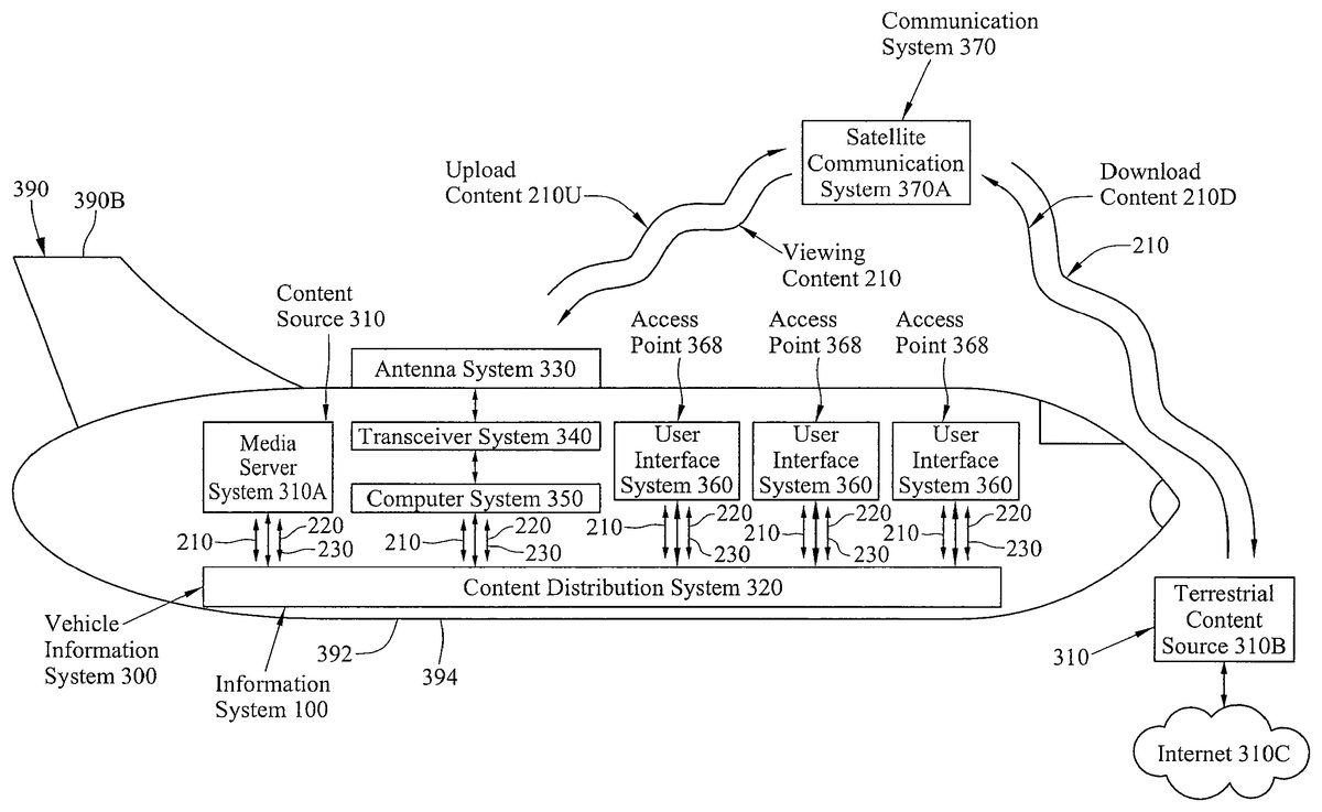
Although the information system100can be disposed in a fixed location, such as a building, the information system100likewise can advantageously be applied in portable system applications. Turning toFIGS. 2A-B, the information system100is shown as comprising a vehicle information system300that can be configured for installation aboard a wide variety of vehicles390. Exemplary types of vehicles can include an automobile390A (shown inFIG. 2A), an aircraft390B (shown inFIG. 2B), a bus, a recreational vehicle, a boat, and/or a locomotive, or any other type of passenger vehicle without limitation. If installed on an aircraft390B as illustrated inFIG. 2B, for example, the vehicle information system300can comprise a conventional aircraft passenger in-flight entertainment system, such as the Series 2000, 3000, eFX, and/or eX2 in-flight entertainment system as manufactured by Panasonic Avionics Corporation (formerly known as Matsushita Avionics Systems Corporation) of Lake Forest, Calif.
As shown inFIGS. 2A-B, the vehicle information system300comprises at least one conventional content source310and one or more user (or passenger) interface systems360that communicate via a real-time content distribution system320. Each content source310can be provided in the manner set forth in the co-pending U.S. patent applications, entitled “SYSTEM AND METHOD FOR DOWNLOADING FILES,” Ser. No. 10/772,565, filed on Feb. 4, 2004; entitled “SYSTEM AND METHOD FOR MANAGING CONTENT ON MOBILE PLATFORMS,” Ser. No. 11/123,327, filed on May 6, 2005; entitled “PORTABLE MEDIA DEVICE AND METHOD FOR PRESENTING VIEWING CONTENT DURING TRAVEL,” Ser. No. 11/154,749, filed on Jun. 15, 2005; entitled “SYSTEM AND METHOD FOR RECEIVING BROADCAST CONTENT ON A MOBILE PLATFORM DURING INTERNATIONAL TRAVEL,” Ser. No. 11/269,378, filed on Nov. 7, 2005; entitled “SYSTEM AND METHOD FOR INTERFACING A PORTABLE MEDIA DEVICE WITH A VEHICLE INFORMATION SYSTEM,” Ser. No. 12/210,624, filed on Sep. 15, 2008; entitled “PORTABLE USER CONTROL DEVICE AND METHOD FOR VEHICLE INFORMATION SYSTEMS,” Ser. No. 12/210,689, filed on Sep. 15, 2008; entitled “SYSTEM AND METHOD FOR RECEIVING BROADCAST CONTENT ON A MOBILE PLATFORM DURING TRAVEL,” Ser. No. 12/237,253, filed on Sep. 24, 2008; and entitled “SYSTEM AND METHOD FOR PRESENTING ADVERTISEMENT CONTENT ON A MOBILE PLATFORM DURING TRAVEL,” Ser. No. 12/245,521, filed on Oct. 3, 2008, which are assigned to the assignee of the present application and the respective disclosures of which are hereby incorporated herein by reference in their entireties.
The content sources310can include one or more internal content sources, such as server system310A, that are installed aboard the vehicle390and/or remote (or terrestrial) content sources310B that can be external from the vehicle390. The server system310A can be provided as an information system controller for providing overall system control functions for the vehicle information system300and/or at least one media (or file) server system, as illustrated inFIGS. 2A-B), for storing preprogrammed content and/or downloaded viewing content210D, as desired. The server system310A can include, and/or communicate with, one or more conventional peripheral media storage systems (not shown), including optical media devices, such as a digital video disk (DVD) system or a compact disk (CD) system, and/or magnetic media systems, such as a video cassette recorder (VCR) system or a hard disk drive (HDD) system, of any suitable kind, for storing the preprogrammed content and/or the downloaded viewing content210D.
Being configured to distribute and/or present the viewing content210provided by one or more selected content sources310, the vehicle information system300can communicate with the content sources310in real time and in any conventional manner, including via wired and/or wireless communications. The vehicle information system300and the terrestrial content source310B, for example, can communicate in any conventional wireless manner, including directly and/or indirectly via an intermediate communication system370, such as a satellite communication system370A. The vehicle information system300thereby can receive download viewing content210D from a selected terrestrial content source310B and/or transmit upload viewing content210U, including navigation and other control instructions, to the terrestrial content source310B. As desired, the terrestrial content source310B can be configured to communicate with other terrestrial content sources (not shown). The terrestrial content source310B is shown inFIG. 2Bas providing access to the Internet310C. Although shown and described as comprising the satellite communication system370A for purposes of illustration, it is understood that the communication system370can comprise any conventional type of wireless communication system, such as a cellular communication system (not shown) and/or an Aircraft Ground Information System (AGIS) communication system (not shown).
To facilitate communications with the terrestrial content sources310B, the vehicle information system300can include an antenna system330and a transceiver system340for receiving the viewing content from the remote (or terrestrial) content sources310B as shown inFIGS. 2A-B. The antenna system330preferably is disposed outside the vehicle390, such as an exterior surface394of a fuselage392of the aircraft390B. The antenna system330can receive viewing content210from the terrestrial content source310B and provide the received viewing content210, as processed by the transceiver system340, to a computer system350of the vehicle information system300. The computer system350can provide the received viewing content210to the media server system310A and/or to one or more of the user interfaces360, as desired. Although shown and described as being separate systems for purposes of illustration, the computer system350and the media server system310A can be at least partially integrated.
The vehicle information system elements, including the content sources310and the user interface systems360, are shown inFIGS. 2A-Bas communicating via the content distribution system320.FIG. 3illustrates an exemplary content distribution system320for the vehicle information system300. The content distribution system320ofFIG. 3couples, and supports communication between a headend system310H, which includes the content sources310, and the plurality of user interface systems360. The distribution system320as shown inFIG. 3is provided in the manner set forth co-pending U.S. patent application, entitled “SYSTEM AND METHOD FOR ROUTING COMMUNICATION SIGNALS VIA A DATA DISTRIBUTION NETWORK,” Ser. No. 11/277,896, filed on Mar. 29, 2006, and in U.S. Pat. Nos. 5,596,647, 5,617,331, and 5,953,429, each entitled “INTEGRATED VIDEO AND AUDIO SIGNAL DISTRIBUTION SYSTEM AND METHOD FOR USE ON COMMERCIAL AIRCRAFT AND OTHER VEHICLES,” which are assigned to the assignee of the present application and the respective disclosures of which are hereby incorporated herein by reference in their entireties. Alternatively, and/or additionally, the distribution system320can be provided in the manner set forth in the co-pending U.S. patent application “OPTICAL COMMUNICATION SYSTEM AND METHOD FOR DISTRIBUTING CONTENT ABOARD A MOBILE PLATFORM DURING TRAVEL,” Ser. No. 12/367,406, filed Feb. 6, 2009, which is assigned to the assignee of the present application and the disclosure of which is hereby incorporated herein by reference in its entirety.
As desired, the distribution system320likewise can include a network management system (not shown) provided in the manner set forth in co-pending U.S. patent applications, entitled “SYSTEM AND METHOD FOR IMPROVING NETWORK RELIABILITY,” Ser. No. 10/773,523, filed on Feb. 6, 2004, and entitled “SYSTEM AND METHOD FOR IMPROVING NETWORK RELIABILITY,” Ser. No. 11/086,510, filed on Mar. 21, 2005, which are assigned to the assignee of the present application and the respective disclosures of which are hereby incorporated herein by reference in their entireties.
As illustrated inFIG. 3, the distribution system320can be provided as a plurality of area distribution boxes (ADBs)322, a plurality of floor disconnect boxes (FDBs)323, and a plurality of seat electronics boxes (SEBs) (and/or premium seat electronics boxes (PSEBs))324being configured to communicate in real time via a plurality of wired and/or wireless communication connections325. The distribution system320likewise can include a switching system321for providing an interface between the distribution system320and the headend system310H. The switching system321can comprise a conventional switching system, such as an Ethernet switching system, and is configured to couple the headend system310H with the area distribution boxes322. Each of the area distribution boxes322is coupled with, and communicates with, the switching system321.
Each of the area distribution boxes322, in turn, is coupled with, and communicates with, at least one floor disconnect box323. Although the area distribution boxes322and the associated floor disconnect boxes323can be coupled in any conventional configuration, the associated floor disconnect boxes323preferably are disposed in a star network topology about a central area distribution box322as illustrated inFIG. 3. Each floor disconnect box323is coupled with, and services, a plurality of daisy-chains of seat electronics boxes324. The seat electronics boxes324, in turn, are configured to communicate with the user interface systems360. Each seat electronics box324can support one or more of the user interface systems360.
As desired, the floor disconnect boxes323advantageously can be provided as routing systems and/or interconnected in the manner set forth in the above-referenced co-pending U.S. patent application, entitled “SYSTEM AND METHOD FOR ROUTING COMMUNICATION SIGNALS VIA A DATA DISTRIBUTION NETWORK,” Ser. No. 11/277,896, filed on Mar. 29, 2006. The distribution system320can include at least one FDB internal port bypass connection325A and/or at least one SEB loopback connection325B. Each FDB internal port bypass connection325A is a communication connection325that permits floor disconnect boxes323associated with different area distribution boxes322to directly communicate. Each SEB loopback connection325B is a communication connection325that directly couples the last seat electronics box324in each daisy-chain of seat electronics boxes324for a selected floor disconnect box323as shown inFIG. 3. Each SEB loopback connection325B therefore forms a loopback path among the daisy-chained seat electronics boxes324coupled with the relevant floor disconnect box323.
Returning toFIGS. 2A-B, the user interface systems360are provided for selecting viewing content210and for presenting the selected viewing content210. As desired, the user interface systems360can comprise conventional passenger interfaces and can be provided in the manner set forth in the above-referenced co-pending U.S. patent application, entitled “PORTABLE MEDIA DEVICE AND METHOD FOR PRESENTING VIEWING CONTENT DURING TRAVEL,” Ser. No. 11/154,749, filed on Jun. 15, 2005, as well as in the manner set forth in the co-pending U.S. patent application, entitled “SYSTEM AND METHOD FOR PRESENTING HIGH-QUALITY VIDEO TO PASSENGERS ON A MOBILE PLATFORM,” Ser. No. 60/673,171, filed on Apr. 19, 2005, the disclosure of which is hereby incorporated herein by reference in its entirety.
FIG. 4Aprovides a view of a passenger cabin380of a passenger vehicle390, such as the automobile390A (shown inFIG. 2A) and/or the aircraft390B (shown inFIG. 2B), aboard which the vehicle information system300has been installed. The passenger cabin380is illustrated as including a plurality of passenger seats382, and each passenger seat382is associated with a selected user interface system360. Each user interface system360can include a video interface system362and/or an audio interface system364. Exemplary video interface systems362can include overhead cabin display systems362A with central controls, seatback display systems362B or armrest display systems (not shown) each with individualized controls, crew display panels, and/or handheld presentation systems. The audio interface systems364can be provided in any conventional manner, including an overhead speaker system364A, the handheld presentation systems, and/or headphones coupled with an audio jack provided, for example, at an armrest388of the passenger seat382. A speaker system likewise can be associated with the passenger seat382, such as a speaker system364B disposed within a base384B of the passenger seat382and/or a speaker system364C disposed within a headrest384C of the passenger seat382. In a preferred embodiment, the audio interface system364can include an optional noise-cancellation system for further improving sound quality produced by the audio interface system364.
The video interface systems362and the audio interface systems364can be installed at any suitable cabin surface, such as a seatback386, wall396, ceiling, and/or bulkhead, or an armrest388of a passenger seat382in any conventional manner including via a mounting system363provided in the manner set forth co-pending U.S. patent applications, entitled “SYSTEM AND METHOD FOR MOUNTING USER INTERFACE DEVICES,” Ser. No. 11/828,193, filed on Jul. 25, 2007, and entitled “USER INTERFACE DEVICE AND METHOD FOR PRESENTING VIEWING CONTENT,” Ser. No. 11/835,371, filed on Aug. 7, 2007, which are assigned to the assignee of the present application and the respective disclosures of which are hereby incorporated herein by reference in their entireties.
As shown inFIG. 4A, the user interface system360likewise can include an input system366for permitting the user (or passenger) to communicate with the vehicle information system300, such as via an exchange of control signals220. For example, the input system366can permit the user to enter one or more user instructions230for controlling the operation of the vehicle information system300. Illustrative user instructions230can include instructions for initiating communication with the content source310, instructions for selecting viewing content210for presentation, and/or instructions for controlling the presentation of the selected viewing content210. If a fee is required for accessing the viewing content210, payment information likewise can be entered via the input system366.
The input system366can be provided in any conventional manner and typically includes one or more switches (or pushbuttons), such as a keyboard or a keypad, and/or a pointing device, such as a mouse, trackball, or stylus. As desired, the input system366can be at least partially integrated with, and/or separable from, the associated video interface system362and/or audio interface system364. For example, the video interface system362and the input system366can be provided as a touchscreen display system. The input system366likewise can include one or more input ports (not shown) for coupling a peripheral input device (not shown), such as a full-size computer keyboard, an external mouse, and/or a game pad, with the vehicle information system300.
Preferably, at least one of the user interface systems360includes a wired and/or wireless access point368, such as a conventional communication port (or connector), for coupling a personal user control device200(shown inFIG. 4B) with the vehicle information system300. Passengers (not shown) who are traveling aboard the vehicle390thereby can enjoy personally-selected viewing content during travel. The access point368is located proximally to an associated passenger seat382and can be provided at any suitable cabin surface, such as a seatback386, wall396, ceiling, and/or bulkhead.
Turning toFIG. 4B, the personal user control devices200and the vehicle information system300are shown as communicating via respective access points368. Being provided in the manner set forth above with reference toFIG. 1, the illustrated personal user control devices200each include a user interface system290. The user interface systems290can comprise a video display system240for visually presenting the viewing content210and/or an audio system250for audibly presenting the viewing content210. Each user interface system290likewise can include a user control system260, which can be provided in any conventional manner and typically includes one or more switches (or pushbuttons), such as a keyboard or a keypad, and/or a pointing device, such as a mouse, trackball, or stylus. The personal user control devices200thereby can select desired viewing content210and control the manner in which the selected viewing content210is received and/or presented.
The personal user control devices200likewise include a communication port (or connector)270. The communication port270enables the personal user control devices200to communicate with the vehicle information system300via the access points368of the user interface systems360. As illustrated with personal user control device200A, the communication port270and the access points368can supported wireless communications; whereas, support for wired communications between the communication port270and the access points368via a communication cable assembly500is shown with personal user control device200B. When the communication port270and the access points368are in communication, the vehicle information system300supports a simple manner for permitting the associated personal user control device200to be integrated with the vehicle information system300using a user-friendly communication interface.
When the personal user control device200and the vehicle information system300are in communication, the vehicle information system300can perform a plurality of integration tasks simultaneously, enabling the personal user control device200to become fully integrated with the vehicle information system300via a selected access point368. The system elements of the vehicle information system300and the personal user control device200thereby become interchangeable. The personal user control device200likewise can receive control signals (or commands)220and/or operating power220P from the vehicle information system300. Thereby, the personal user control device200advantageously can become a seamless part of the vehicle information system300.
For example, user instructions230(shown inFIGS. 2A-B) for controlling the operation of the vehicle information system300can be provided via the input system366of the vehicle information system300and/or the user control system260of the personal user control device200. In other words, the input system366of the vehicle information system300and/or the user control system260of the personal user control device200can be used to select viewing content210and control the manner in which the selected viewing content210is received and/or presented. The selected viewing content210can be provided by a relevant content source310(shown inFIGS. 2A-B) of the vehicle information system300and/or by storage media (not shown) disposed within the personal user control device200. A video portion of the selected viewing content210thereby can be presented via the video presentation system362of the vehicle information system300and/or the video display system240of the personal user control device200. The audio presentation system364of the vehicle information system300and/or the audio system250of the personal user control device200can be used to present an audio portion of the selected viewing content210. If the video display system240of the personal user control device200is much smaller than the video presentation system362of the vehicle information system300, a passenger (or user) may prefer to view the selected viewing content210via the larger video presentation system362.
When no longer in use and/or direct physical contact with the personal user control device200is not otherwise required, the personal user control device200can be stored at the passenger seat382. For example, the passenger seat382can include a storage compartment389for providing storage of the personal user control device200. The storage compartment389can be provided in any conventional manner and at any suitable portion of the passenger seat382. As illustrated with passenger seat382B, the personal user control device200can be placed in a storage pocket389B formed in the armrest388of the passenger seat382B. The storage compartment389likewise can be provided on the seatback386and/or the headrest384of the passenger seat382. Storage compartment389A of passenger seat382A, for example, is shown as being formed on the lower seatback386of the passenger seat382A. As desired, the storage compartment389can comprise an overhead storage compartment, a door storage compartment, a storage compartment provided underneath the passenger seat382, or any other type of conventional storage compartment, such as a glove compartment, trunk, or closet, available in the passenger vehicle390.
As set forth above, the personal user control device200can support wired and/or wireless communications with the vehicle information system300.FIG. 5Aillustrates the personal user control device200communicating with the vehicle information system300via an exemplary communication cable assembly500. The communication cable assembly500can comprise a conventional communication assembly, such as a Universal Serial Bus (USB) cable assembly, having a communication cable510with a suitable cable length and being terminated with two or more communication connectors (or ports)520. As shown inFIG. 5A, the communication cable510is terminated with a system communication connector (or port)520A for removably coupling with the vehicle information system300and a device communication connector (or port)520B for removably coupling with the personal user control device200. The system communication connector520A and the device communication connector520B each can comprise any conventional type of connector system. Although shown and described as being provided on respective opposite end regions510A,510B of the communication cable assembly500for purposes of illustration only, the system and device communication connectors520A,520B can be provided the communication cable assembly500in any conventional manner.
The communication cable assembly500can be utilized to transmit a variety of diverse signal types, such as audio signals, video signals, data signals, control signals220, and operating power220P signals. The communication cable510preferably is provided in a manner to minimize interference (or crosstalk) among these diverse signals in the manner set forth in more detail in the above-referenced related nonprovisional patent application, “SYSTEM AND METHOD FOR INTERFACING A PORTABLE MEDIA DEVICE WITH A VEHICLE INFORMATION SYSTEM,” Ser. No. 12/210,624, filed Sep. 15, 2008. The access point368of the vehicle information system300can be provided as a communication connector (or port) that is configured to cooperate with the system communication connector520A. The access point368thereby can receive, and couple with, the system communication connector520A. As desired, the system communication connector520A likewise can be removed (or disconnected) from the access point368.
The device communication connector520B of the communication cable assembly500likewise can be received by, and removably couple with, the communication connector270of the personal user control device200. In other words, the device communication connector520B of the communication cable assembly500can cooperate with the communication connector270of the personal user control device200. The coupling between the system communication connector520A and the access point368and/or the coupling between the device communication connector520B and the communication connector270can be provided as a break-away communication connector system in the manner set forth in more detail in the above-referenced related nonprovisional patent application, “MEDIA DEVICE INTERFACE SYSTEM AND METHOD FOR VEHICLE INFORMATION SYSTEMS,” Ser. No. 12/210,636, filed Sep. 15, 2008, and “MEDIA DEVICE INTERFACE SYSTEM AND METHOD FOR VEHICLE INFORMATION SYSTEMS,” Ser. No. 12/210,652, filed Sep. 15, 2008.
The personal user control device200is shown as including a user interface system290that is disposed on (and/or within) a handheld case (or housing)280. The user interface system290can include a user control system260, a video display system240, and/or an audio system250each being provided in the manner set forth in more detail above with reference toFIG. 4B. Preferably including no (or a limited number of) dedicated buttons, the video display system240and the user control system260of the user interface system290can be provided as a touchscreen display system for interfacing with the vehicle information system300. If provided as the touchscreen display system, the video display system240can present a plurality of user-selectable icons260A that are associated with selected system features, viewing content210, and/or system operation mode associated with the vehicle information system300. The user interface system290thereby provides a simplified user interaction layout. As desired, the viewing content210can be presented via the video display system240and/or the audio system250of the personal user control device200and/or the video presentation system362(shown inFIGS. 4A-B) and/or the audio presentation system364(shown inFIGS. 4A-B) of the vehicle information system300(shown inFIGS. 2A-B). The viewing content210preferably can be viewed with special effects, such as three-dimensional (3D) viewing capabilities.
The audio system250of the personal user control device200can comprise any conventional type of audio presentation system and, as desired, can be provided as an internal speaker system (not shown) that is disposed on (and/or within) a handheld case (or housing)280. As shown inFIG. 5A, for example, the audio system250of the personal user control device200can include at least one audio connector system for coupling the personal user control device200with a peripheral audio presentation system (not shown). Exemplary peripheral audio presentation systems can include headphones, speakers, and/or amplifiers. In a preferred embodiment, the audio system250can provide operating power to the peripheral audio presentation system. Thereby, powered peripheral audio presentation devices, such as noise canceling headphones, can receive the operating power via the audio system250.
When coupled via the communication cable assembly500, the personal user control device200and the vehicle information system300can initiate, and maintain, communications. The viewing content210, including any onboard service and local viewing content, thereby can be selected by the user control system260of the personal user control device200for presentation on the video presentation system362(shown inFIGS. 4A-B) and/or the audio presentation system364(shown inFIGS. 4A-B) of the vehicle information system300. Alternatively, and/or additionally, the video display system240and/or the audio system250of the personal user control device200can be adapted to present the selected viewing content210. Since the personal user control device200can be advantageously configured to multitask, a first selection of viewing content210, such as a motion picture can be presented via the video presentation system362and the audio presentation system364of the vehicle information system300; while, the video display system240and/or the audio system250of the personal user control device200can present a second selection of viewing content210, such as viewing content210provided by the Internet310C (shown inFIG. 2B).
The personal user control device200and the vehicle information system300preferably communicate via a wireless communication system. As illustrated inFIG. 5B, the access point368of the vehicle information system300is shown as comprising a wireless access point; whereas, the communication port270of the personal user control device200is provided as a wireless communication port. When disposed within a predetermined range (or proximity) of the wireless access point368, the personal user control device200can communicate with the vehicle information system300via the wireless access point368. The personal user control device200thereby can automatically detect that it is in a “home” mode and/or can automatically detect a range and/or type of any compatible devices. Viewing content210and/or control signals (or commands)220can be exchanged between the wireless access point368of the vehicle information system300and the wireless communication port270of the personal user control device200. The vehicle information system300can support any conventional wireless communication protocol with the personal user control device200. Exemplary wireless protocols include a wireless fidelity (Wi-Fi) protocol in accordance with Institute of Electrical and Electronics Engineers (IEEE) Standard 802.11 and/or wireless metropolitan-area network (MAN) protocol, which also are known as a WiMax Wireless Broadband protocol, in accordance with IEEE Standard 802.16.
Turning toFIG. 6A, the user interface system290of the personal user control device200is shown with the video display system240and the user control system260being provided as a touchscreen display system to provide a rich user experience. The touchscreen display system, for example, can employ projected capacitive touchscreen technology. Being providing with a smooth, dead front display area, the touchscreen display system eliminates any ridges (or gaps) in the display area and thereby can be fairly spill-proof and easy to clean. Exemplary capacitive touchscreen display systems are manufactured by Trident Ltd. of Surrey, United Kingdom, Elo TouchSystems Inc., of Menlo Park, Calif., and TouchKO Inc., of Cedar Park, Tex. If the color mask of the touchscreen display system is disposed between the touchscreen panel and the display, a surface capacitive touchscreen display system may be employed. Although shown and described as comprising capacitive touchscreen technology for purposes of illustration only, the touchscreen display system can be provided using other touchscreen technologies, such as resistive touchscreen technology and/or infrared (IR) touchscreen technology.
The touchscreen display system can present the plurality of user-selectable icons260A in the manner set forth in more detail above with reference toFIGS. 5A-B. More specifically, the user interface system290is shown as presenting a main menu system262that includes basic control selections262A-E and that is part of an hierarchical menu system. One preferred embodiment of the main menu system262is illustrated inFIG. 6A. The user interface system290preferably presents the main menu system262upon being powered (or turned) on or otherwise initialized, and each basic control selection262A-E can be associated with subsequent tiers (or levels) of interactivity and/or control within the hierarchical menu system. Exemplary basic control selections262A-E can include a dining (or food service) control selection262A, a shopping control selection262B, a vehicle information system communication control selection262C, a music control selection262D, and/or a television (or movies) control selection262E. As desired, one or more of the user-selectable icons260A can be presented with special effects, such as a swirling icon.
Each of the basic control selections262A-E can be associated with identifying indicia264that identifies the relevant control selection. As shown inFIG. 6A, the identifying indicia264can identify the basic control selections262A-E in any conventional manner, including use of text264A, such as words or abbreviations, and/or at least one symbol (or icon)264B that identify the relevant control selection. The textual description264A can be provided in one or more relevant languages and preferably is changeable such that a suitable language is presented based upon the geographical location of the vehicle information system300. Each tier of interactivity and/or control within the hierarchical menu system likewise can be associated with identifying indicia264, such as a textual description264A as illustrated inFIG. 6A. Since the operation of the personal user control device200preferably is software programmable, each feature of the user interface system290can be customized as desired. For example, the identifying indicia264, including the textual descriptions264A and/or the symbols264B, the colors, the basic control selections262A-E, the main menu system262, and/or even the hierarchical menu system can be readily changed to suit the tastes of the user or, as relevant, the branding of the vehicle operator.
Alternate preferred embodiments of the main menu system262that can be presented by the user interface system290are shown inFIGS. 7A-F. As illustrated inFIGS. 7A-F, each level of the menu system262can include any suitable arrangement and/or number of control selections262A-E. The number of control selections262A-E for a selected level of the menu system262typically is based upon the number of control options associated with the menu system level. The identifying indicia264for the control selections262A-E likewise can be customized such that the identifying indicia264suit the tastes of the user or, as relevant, the branding of the vehicle operator. For example, the hierarchical menu system can include a setup menu level, which permits a user to select custom identifying indicia264and otherwise customize the presentation of one or more system levels of the hierarchical menu system. Although shown and described with reference to the main menu system262of the hierarchical menu system for purposes of illustration only, the discussion herein of the main menu system262can equally apply to any menu level within the hierarchical menu system.
Turning toFIG. 7A, for example, illustrative identifying indicia264for the control selections262A-E are shown. The control selections262A-E can be provided in any conventional manner and preferably identify the related system function of the vehicle information system300(shown inFIGS. 2A-B). As shown inFIG. 7A, the control selections262A-E can be provided in a horizontal arrangement, being aligned with a longer dimension of the video display system240of the personal user control device200. The control selections262A-E likewise can be provided in a vertical arrangement as illustrated inFIG. 7B.
If provided with at least one accelerometer (not shown), for example, the personal user control device200can detect an orientation of the personal user control device200and portray the control selections262A-E in either portrait mode or landscape mode, whichever is suitable. In other words, the at least one accelerometer can sense the orientation of the personal user control device200and adjust the presentation of the control selections262A-E, or any other viewing content210(shown inFIGS. 2A-B), in accordance with the orientation of the personal user control device200. The at least one accelerometer likewise can effect the manner in which the viewing content210is presented on the video presentation system362(shown inFIGS. 4A-B) and/or the audio presentation system364(shown inFIGS. 4A-B) of the vehicle information system300. For example, as the personal user control device200is moved closer to (or further from) the video presentation system362, the viewing content210as presented on the video presentation system362can become enlarged (or reduced). Similarly, the volume of the viewing content210as presented by the audio presentation system364can increase (or decrease) as the personal user control device200is moved closer to (or further from) the video presentation system362and/or the audio presentation system364.
FIG. 7Cshows that the user control system260of the user interface system290can be provided (or arranged) as a control system toolbar. The control system toolbar can be presented in any conventional manner and can include any suitable control system functions. As illustrated inFIG. 7C, control system toolbar can be disposed adjacent to the control selections262A-E of the main menu system262. To facilitate navigation of the hierarchical menu system, the control system functions of the control system toolbar is shown as including a main menu control function260H for directly returning to the main (or home) menu system262from any menu level within the hierarchical menu system. The control system functions of the control system toolbar likewise can include a previous level control function260R for directly returning to a previously-viewed menu level (or a higher/lower menu level) within the hierarchical menu system. An alternative embodiment of the identifying indicia264for the control selections262A-E and the control system toolbar of the user interface system290is illustrated inFIG. 7D.
As desired, the identifying indicia264for the control selections262A-E can be provided in a circular arrangement as illustrated inFIG. 7E. The control system toolbar is disposed adjacent to the circular arrangement of the control selections262A-E. Advantageously, the control system toolbar ofFIG. 7Eis shown as including selection information296, such as a brief summary or abstract, related to the control selections262A-E. The user interface system290likewise is shown as including specialized indicia292,294associated with the user or, as relevant, the branding of the vehicle operator. As illustrated inFIG. 7E, the specialized indicia292,294can include a stylized name and/or a logo, such as a trademarked name and/or logo, associated with the vehicle operator.FIG. 7Fillustrates that the identifying indicia264for the control selections262A-E can be fully customized to suit the tastes of the user or, as relevant, the branding of the vehicle operator.
Returning toFIG. 6A, the user control system260of the user interface system290can include one or more user controls266,268that are at least partially integrated with the touchscreen display system, as desired. Exemplary user controls can include an audio adjustment control system266and/or a menu selection system268. The audio adjustment control system266can be provided in any conventional manner and is shown inFIG. 6Aas having an audio volume increase control266U and an audio volume decrease control266D. As desired, the audio adjustment control system266can be included with the control system toolbar discussed above with reference toFIG. 7C. The menu selection system268likewise can be provided in any conventional manner and enables a user to view the basic control selections262A-E within the main menu system262. As illustrated inFIG. 6A, the menu selection system268can include a left scroll control268L and a right scroll control268R. Advantageously, the user interface system290can indicate the current basic control selection262C by highlighting or otherwise emphasizing the identifying indicia264associated with the current basic control selection262C. The current basic control selection262C ofFIG. 6Ahas been emphasized by enlarging the associated symbol264B; whereas, the current basic control selection262C ofFIG. 7Acan be identified via the term “select,” which is included within the identifying indicia264.
The personal user control device200can be disposed within a handheld case (or housing)280. The handheld housing280can be provided with any suitable shape, size, texture, and/or color and is illustrated inFIG. 6Aas having a rectangular shape. As desired, the personal user control device200can be disposed, partially and/or completely, within ergonomic (or protective) cover assembly282, such as a cast rubber, silicon, or plastic boot, as shown inFIG. 6B. The ergonomic cover assembly282forms a cover opening282A that is configured to receive the personal user control device200and that is defined by cover interior surfaces282B. Alternatively, or additionally, the handheld housing280can be formed with the shape, size, texture, and/or color of the ergonomic cover assembly282.
When the personal user control device200is received within the cover opening282A of the cover assembly282, the cover interior surfaces282B engages the handheld housing280of the personal user control device200such that the cover assembly282provides an ergonomic grip282D for the personal user control device200. The cover assembly282likewise can provide control interfaces282C for permitting a user to observe, activate, and otherwise interact with the user control system260through the cover assembly282. Preferably, the cover assembly282is formed from a translucent (or transparent) material and/or the user control system260is illuminated to facilitate interaction with the user control system260via the cover assembly282. In other words, the touchscreen display system can project colors, text, and/or symbols associated with the user control system260through the cover assembly282such that the user control system260is visible. As desired, the personal user control device200subsequently can be separated from the cover assembly282.
To further enhance the ergonomic form of the personal user control device200, the handheld housing280can be provided with one or more tapered (or contoured) housing regions284as illustrated inFIG. 6C. The tapered housing regions284can be provided on any suitable surface of the handheld housing280and are provided in a manner that makes the personal user control device200more comfortable to hold. For example, the handheld housing280is shown as having tapered opposite end regions284A,284B. The handheld housing280likewise can include at least one tapered side regions284C, as desired. The shape, size, texture, and/or color of the handheld housing280can be readily provided in a manner that suits the tastes of the user or, as relevant, the branding of the vehicle operator. The personal user control device200likewise can include identifying indicia, such as text and/or a symbol (or icon), on the handheld housing280. As shown inFIG. 6D, a colored band286can be disposed on a side region of the handheld housing280.
In the manner set forth above with reference toFIGS. 6A-D, the video display system240and the user control system260of the personal user control device200can be provided as a touchscreen display system that is disposed on (and/or within) the handheld housing280. Turning toFIG. 8A, a display overlay system400is shown for use in conjunction with the personal user control device200. The personal user control device200and the display overlay system400can be provided as separate systems, as illustrated inFIG. 8A, and/or can be at least partially integrated (or coupled). The display overlay system400includes an overlay housing420that is configured to cooperate with the handheld housing280of the personal user control device200. As shown inFIG. 8A, the overlay housing420forms an overlay opening (not shown) for receiving, and engaging, the handheld housing280. The display overlay system400and the personal user control device200thereby can couple. As desired, the overlay housing420subsequently can disengage the handheld housing280such that the display overlay system400and the personal user control device200are removably coupled.
The display overlay system400includes at least one user controller interface portion410. Each user controller interface portion410includes one or more button regions412that can be pressed by a user and that, if pressed, can contact corresponding locations of the touchscreen display system when the display overlay system400and the personal user control device200are coupled. The user thereby interacts with the touchscreen display system of the personal user control device200via the display overlay system400. By associating (or mapping) a predetermined function with each location of the touchscreen display system, activation of a selected button region412of a selected user controller interface portion410can initiate the predetermined function. The personal user control device200can be configured for use with a plurality of the display overlay systems400with different numbers, configurations, and/or arrangements of the user controller interface portion410such that the user interface system290(shown inFIG. 4B) of the personal user control device200can be readily customized. In other words, the personal user control device200can be customized via selection of an appropriate display overlay system400.
As shown inFIG. 8A, the display overlay system400can have two user controller interface portions410A,410B each including four button region412. Each controller interface portions410A,410B can include any suitable number, arrangement, and/or configuration of button regions412. The button region412ofFIG. 8Acan be flush with the overlay housing420and provide tactile feedback. Preferably, the button regions412are associated with identifying indicia414for identifying the functions associated with the button regions412. The identifying indicia414for the first user controller interface portion410A is shown as comprising directional arrows; whereas, the identifying indicia414for the second user controller interface portion410B can include text, numbers, or letters. Although shown and described as being button regions412for purposes of illustration only, the user controller interface portions410can comprise any conventional type of control interface, such as a pushbutton switch, a rocker switch, a slider switch (or game pad) (shown inFIG. 8B), a rotatable switch, and/or a toggle switch, without limitation.
The identifying indicia414can be associated with the button regions412in any conventional manner. For example, the identifying indicia414can be formed, or applied, on the overlay housing420. The identifying indicia414can be formed from cutout regions formed within the button regions412such that light from the touchscreen display system of the personal user control device200can pass through the cutout regions. The light from the touchscreen display system can be provided with any suitable color and/or luminance. As desired, the button regions412of the display overlay system400likewise can be formed from a translucent (or transparent) material. The identifying indicia414thereby can be presented as a display graphic by the touchscreen display system of the personal user control device200and seen through the translucent button regions412. The button regions412can be disposed within a user interface region450(shown inFIG. 8C) of the display overlay system400, and at least a portion of the user interface region450can be formed from a translucent (or transparent) material.
Preferably, the identifying indicia414illuminate or otherwise become visible only when the associated button regions412are active (or in use) and blend into the overlay housing420when the associated button regions412are not active. If a selected controller interface portion410is associated with a game controller, for example, the identifying indicia414associated with the selected controller interface portion410can illuminate when the personal user control device200(or the vehicle information system300) enters a game mode. For example,FIG. 8Bshows that the display overlay system400can include a switching system430for activating a game mode of the personal user control device200.
One manner for recessing the controller interface portion410within the overlay housing420of the display overlay system400is illustrated inFIG. 8B. As shown inFIG. 8B, the overlay housing420can provide a recessed (or dished-out) region422adjacent to an associated controller interface portion410. The recessed region422of the overlay housing420inhibits the associated controller interface portion410from extending beyond the surface of the overlay housing420. In other words, the recessed region422enables the controller interface portion410to be mounted flush with the overlay housing420.
The display overlay system400can be coupled with (or disposed on) the handheld housing280of the personal user control device200in any conventional manner. To facilitate customization of the user interface system290(shown inFIG. 4B) presented by the handheld housing280, the display overlay system400preferably is removably and/or adjustably coupled with the handheld housing280. Turning toFIG. 8C, for example, the display overlay system400can include an overlay magnetic coupling system440that is adapted to communicate with a device magnetic coupling system288of the personal user control device200. The overlay magnetic coupling system440can be provided at one or more suitable regions of the overlay housing420and can be disposed within (or on a surface of) the overlay housing420. Similarly, the device magnetic coupling system288can be provided at one or more suitable regions of the handheld housing280and can be disposed within (or on a surface of) the handheld housing280. Thereby, the display overlay system400can be provided as a removable face plate for the personal user control device200and can engage the personal user control device200.
Alternatively, and/or additionally, the display overlay system400can be rotatably coupled with the handheld housing280of the personal user control device200. As shown inFIG. 8D, for example, a hinge system460can couple the display overlay system400and the handheld housing280. The hinge system460can be provided in any conventional manner and can be connect to any suitable surface of the overlay housing420and/or the handheld housing280. The display overlay system400thereby can be rotated adjacent to the touchscreen display system of the personal user control device200to provide the user interface system290(shown inFIG. 4B). The display overlay system400likewise can be rotated away from the touchscreen display system when not in use. As shown inFIG. 8D, the handheld housing280can advantageously include a storage surface289, such as a back surface (or a surface opposite the touchscreen display system), of the handheld housing280. The hinge system460thereby can dispose the display overlay system400adjacent to the storage surface289when the display overlay system400is not in use. As desired, the storage surface289can form one or more recesses289A for receiving the user controller interface portion410when the display overlay system400adjacent to the storage surface289.
Turning toFIG. 8E, the display overlay system400can be provided as a plurality of separate display overlay subsystems400A,400B. The display overlay system400is shown inFIG. 8Eas comprising two overlay subsystems400A,400B. The overlay housing420of each overlay subsystems400A,400B forms an opening470for receiving a selected portion of the handheld housing280of the personal user control device200. The overlay subsystems400A,400B each can receive any suitable portion of the handheld housing280and are illustrated inFIG. 8Eas receiving opposite end regions of the handheld housing280. When coupled with the handheld housing280, the overlay subsystems400A,400B can extend partially, as shown inFIG. 8E, and/or completely over the touchscreen display system of the personal user control device200. At least a portion of the touchscreen display system between the overlay subsystems400A,400B can remain exposed if the overlay subsystems400A,400B extend partially over the touchscreen display system. The overlay subsystems400A,400B thereby can be formed as opaque rubber (or plastic) grips with one or more translucent (or transparent) plastic user controller interface portions410. After use, the overlay subsystems400A,400B can be stacked to save space.
When configured (or customized) for use as a game controller, the personal user control device200can provide a suitable number, configuration, and/or arrangement of the user controller interface portion410such that the user interface system290(shown inFIG. 4B) of the personal user control device200is customized for use with a selected game. In one preferred embodiment, the user interface system can have a game control system (not shown) built into the personal user control device200. The game control system is not presented until game mode is selected, and any relevant game parts are retracted from the personal user control device200.
The personal user control device200provides a versatile and intuitive user interface system290that can readily be customized for use in any conventional user environment, such as in the home. As desired, the personal user control device200can be provided as a telephone (not shown). When provided as a telephone, the personal user control device200can operate as a dual landline telephone and/or an Internet Protocol (IP) telephone. The user can select a telephone communication protocol, and/or a default telephone communication protocol can be identified during device setup. For emergency telephone calls, such as 9-1-1 calls, a landline telephone communication protocol is automatically selected. The personal user control device200thereby can provide standard home telephone capabilities, including advanced features such as photographs, text messaging, and/or video (or animated) caller identification. The personal user control device200likewise can provide customized user-specific capabilities when provided as a telephone. Exemplary customized user-specific capabilities can include an integrated soft-keyboard, a large text format for elderly (or vision-impaired) users, a baby-sitter mode for providing important telephone numbers, a fun, whimsical interface system290for children, and host (or bridge) contact information for electronic mail (and other) contacts and/or a wireless communication link to cellular data.
The personal user control device200advantageously provides a wide-ranging noise-canceling microphone (not shown) to facilitate state-of-the-art telephone and video conferencing. The personal user control device200can be coupled with an information system100(shown inFIG. 1) via Internet Protocol (IP) technology. A stereo and/or a television thereby can be used to enhance family and business conversations. The personal user control device200also supports a speakerphone mode for simple, hands-free communication.
If an enhanced user control system260(shown inFIG. 4B) is desired, the personal user control device200can dock with one or more peripheral user devices (not shown). The personal user control device200can dock with a specially-fitted keyboard system that can be used, for example, to access the Internet, to type a document, and/or to send an electronic mail (email) message. The personal user control device200thereby can be used as a feedback mechanism for the keyboard system. Preferably, the keyboard system is provided as a dumb device without a communication link and/or batteries such that the personal user control device200can be operated as a modem. The personal user control device200can dock with the keyboard system in any conventional manner, including via a magnetic coupling system.
When the personal user control device200is used in the home, the menu system can be used to control a home security system, including security devices, security lighting, and/or security blinds. The personal user control device200, for example, can continue to control the home security system remotely from outside the house, such as during travel aboard a passenger vehicle390(shown inFIGS. 2A-B). Home closed circuit television security footage likewise can be viewed via the personal user control device200before entering the home. As needed, the personal user control device200can remotely monitor the home security system and present a security alert if an alarm system has been activated.
The personal user control device200likewise can advantageously operate as a universal remote control system. The personal user control device200can be configured to be compatible with any conventional media system, such as an entertainment system. Thereby, the personal user control device200can provide remote control and otherwise interact with the media system. The personal user control device200, for example, can enable and remotely interact with an Internet Protocol television (IPTV) system, a conventional television system, and any other conventional entertainment system. As desired, the personal user control device200can provide remote command and control for an iPod® digital electronic media device and/or an iPhone® digital electronic media device each as manufactured by Apple Computer, Inc., of Cupertino, Calif. The personal user control device200thereby can control and manipulate a playlist of the iPod® digital electronic media device and/or the iPhone® digital electronic media device.
The versatile and intuitive user interface system290of the personal user control device200likewise can be customized for use in a vehicle390(shown inFIGS. 2A-B), such as an automobile390A (shown inFIG. 2A) and/or an aircraft390B (shown inFIG. 2B). Advantageously, the personal user control device200can provide a seamless experience between the home and the vehicle390. The personal user control device200, for example, can carry personalized data and authentication credentials and/or can extend a wireless network interface to the vehicle390. As desired, the personal user control device200likewise can bridge a landline telephone system between the home and the vehicle390. A user thereby can initiate and/or receive home telephone calls via the personal user control device200while traveling in the vehicle390.
The personal user control device200can use a telephone network interface, such as an integrated cellular network interface, and Internet Protocol (IP) characteristics of a home base station. The telephone calls can be conducted (or presented) in any conventional manner, such as via a telephone interface (not shown) installed in the vehicle390. In a preferred embodiment, the personal user control device200can be used to conduct the telephone calls. When used to initiate and/or receive home telephone calls, the personal user control device200advantageously enables the telephone calls to be conducted with consistency, user convenience, and/or personalization for elderly (or young) users.
When used in the vehicle390, the personal user control device200likewise can advantageously operate as a universal remote control system. The personal user control device200thereby can be configured to be compatible for use with any conventional vehicle information system300, including a vehicle entertainment system. For example, the personal user control device200can provide control for a video presentation system362(shown inFIGS. 4A-B) and/or an audio presentation system364(shown inFIGS. 4A-B) of the vehicle information system300.
The personal user control device200can support remote command and control, such as a control signal220(shown inFIGS. 2A-B), for a personal media device (not shown) provided in the manner set forth in the above-referenced co-pending U.S. patent applications, entitled “SYSTEM AND METHOD FOR DOWNLOADING FILES,” Ser. No. 10/772,565, filed on Feb. 4, 2004; entitled “PORTABLE MEDIA DEVICE AND METHOD FOR PRESENTING VIEWING CONTENT DURING TRAVEL,” Ser. No. 11/154,749, filed on Jun. 15, 2005; and entitled “SYSTEM AND METHOD FOR RECEIVING BROADCAST CONTENT ON A MOBILE PLATFORM DURING INTERNATIONAL TRAVEL,” Ser. No. 11/269,378, filed on Nov. 7, 2005, and the above-referenced related nonprovisional patent applications: “MEDIA DEVICE INTERFACE SYSTEM AND METHOD FOR VEHICLE INFORMATION SYSTEMS,” Ser. No. 12/210,636, filed Sep. 15, 2008; and “MEDIA DEVICE INTERFACE SYSTEM AND METHOD FOR VEHICLE INFORMATION SYSTEMS,” Ser. No. 12/210,652, filed Sep. 15, 2008. As desired, the personal media device can be provided as an iPod® digital electronic media device and/or an iPhone® digital electronic media device each as manufactured by Apple Computer, Inc., of Cupertino, Calif.
If the personal media device comprises an iPod® digital electronic media device and/or an iPhone® digital electronic media device, for example, the personal user control device200can communicate with the iPod® digital electronic media device and/or the iPhone® digital electronic media device in the manner set forth in the above-referenced related nonprovisional patent applications: “SYSTEM AND METHOD FOR INTERFACING A PORTABLE MEDIA DEVICE WITH A VEHICLE INFORMATION SYSTEM,” Ser. No. 12/210,624, filed Sep. 15, 2008; “MEDIA DEVICE INTERFACE SYSTEM AND METHOD FOR VEHICLE INFORMATION SYSTEMS,” Ser. No. 12/210,636, filed Sep. 15, 2008; and “MEDIA DEVICE INTERFACE SYSTEM AND METHOD FOR VEHICLE INFORMATION SYSTEMS,” Ser. No. 12/210,652, filed Sep. 15, 2008.
The personal user control device200thereby can provide command and control for the iPod® digital electronic media device and/or the iPhone® digital electronic media device. In one preferred embodiment, the personal user control device200, when used in the vehicle390, can provide command and control for the iPod® digital electronic media device and/or the iPhone® digital electronic media device even if the iPod® digital electronic media device and/or the iPhone® digital electronic media device remain docked at home. As desired, the personal user control device200can provide personalized menu system for each automobile passenger.
The personal user control device200can be customized to operate as a removable in-dash face plate system in a manner similar to conventional vehicular dash face plate systems, such as automotive in-dash plate systems. When used as a removable dash face plate systems, the personal user control device200can provide personalized user settings, including personalized user home-to-vehicle settings and/or personalized user vehicle-to-vehicle settings.
The personal user control device200likewise can be associated with a vehicle navigation system (not shown). As desired, the personal user control device200can comprise the vehicle navigation system and/or can be customized to cooperate with a conventional vehicle navigation system. The personal user control device200thereby can provide personalized (or removable) point-of-interest (POI) information and/or can be associated with (or tied to) a Churchill strategy.
When used in the vehicle390, the personal user control device200likewise can advantageously operate as a game control system. The personal user control device200can be used in conjunction with an add-on game control to customize the personal user control device200for operation as a gaming handset. Thereby, the personal user control device200can facilitate game continuity. In other words, the personal user control device200can use a wireless interface system and/or a physical interface system to pick up an existing game where the game had been left off. Game continuity can be provided via a conventional tag system. As desired, the personal user control device200can enable a wireless communication link to selected games. Exemplary selected games can include simple games and/or low-bandwidth games available via the Internet310C (shown inFIG. 2B).
The personal user control device200advantageously can be employed as a vehicle safety system. When used in an automobile390A, for example, the personal user control device200can replace (and/or supplement) a mirror system by presenting real-time views provided by a vehicle camera system (not shown). The personal user control device200can provide a wired and/or wireless camera interface system for interacting with a rear view vehicle camera system installed aboard the automobile390A. The personal user control device200thereby can present a rear view from the automobile390A rather than relying solely on rear view vehicle mirror systems. The personal user control device200thereby can enhance the functionality of the vehicle camera system. As desired, a vehicle camera system can be installed at any conventional vehicle mirror system location. Standard in-dash features likewise can be migrated to these locations. If customized to operate as a removable in-dash face plate system in the manner set forth above, the personal user control device200can provide conventional face plate functionality while enhancing the functionality of the vehicle camera system.
As desired, the personal user control device200can be customized to operate any conventional vehicle system. For example, the personal user control device200can be customized to operate as a conventional smart key system. The personal user control device200thereby can support providing entry authorization to the vehicle390. Advantageously, the personal user control device200can include programmable, personalized settings for one or more vehicles390. The personal user control device200can automatically detect the relevant vehicle390. The personal user control device200likewise can provide control for the manipulation of an electronic passenger seat382(shown inFIGS. 4A-B). Thereby, existing conventional controls for manipulating the passenger seat382can be eliminated from the vehicle390. The passenger seat382preferably can be manipulated via the personal user control device200at any suitable time, including when an engine system of the vehicle390is not activated (or on).
The personal user control device200likewise can be adapted to readily switch among a plurality of user interface systems290. For example, the personal user control device200can present a first user interface systems290with an interactive look for adults. Upon entry of a preselected authorization code, the personal user control device200can present a second user interface systems290with an interactive look suitable for children. When installed aboard a passenger vehicle390(shown inFIGS. 2A-B), the availability of user interface systems290can be based upon selected predetermined criteria. The user interface system290, for instance, can be made to look like the destination city. If the predetermined criteria comprises passenger class (first class, premium class, business class, economy class, and/or coach class), the personal user control device200can present a user interface system290that is suitable for use with the viewing content accessible in accordance with the relevant passenger class. The selection of the interface systems290can be preformed automatically based, for example, on passenger manifests and/or frequent flyer programs. As desired, the personal user control device200can include a conventional card reader for authorizing enhanced device functionality. The card reader can be configured to read credit cards, frequent flyer cards, etc.
The personal user control device200advantageously can be applied in a wide range of applications. In one embodiment, the personal user control device200can be adapted for use as a customized remote control with multiplayer games, such as card games, board games, arcade games, computer games, and the like without limitation. The personal user control device200, for example, is illustrated inFIG. 9Aas being configured for use with a poker game900. Turning toFIG. 9A, each poker player960can interact with the poker game900via a combination of a personal user control device200and a separate video interface system362, such as a respective seatback display system362B disposed on an adjacent passenger seat382. The respective seatback display systems362B can present a central gaming surface (or location), such as a virtual poker table940, and other indicia associated with the poker game900, simulating the experience of being physically positioned at a tangible poker table (not shown). Preferably, the seatback display systems362B present the poker table940from different perspectives (and/or angles) to provide an effect of sitting around the poker table940. Two or more poker players960can share a common seatback display system362B, as desired.
The poker game900is played in accordance with conventional poker rules, in which the poker players960act in turn. Alternatively, and/or additionally, the personal user control devices200preferably are activated in a predetermined sequence (or order) for inhibiting the poker players960from participating out of turn. As illustrated inFIG. 9A, each poker player960can be associated with one or more wagering tokens (or poker chips)950of at least one denomination and can be dealt at least one playing card920from a card deck910. A selected poker player960A can actively participate in the poker game900via a personal user control device200A in the same manner by which he would participate in the poker game900if seated at the tangible poker table. The personal user control device200A enables the selected poker player960A to communicate with the other poker players960. The selected poker player960A, for example, can place a bet, request one or more playing cards920, and/or discard one or more playing cards920at appropriate times during the poker game900.
During a betting phase of the poker game900, for example, the user controller interface portion410of the personal user control device200A can provide a customized interface with button regions412with identifying indicia414for permitting the selected poker player960A to place a bet, raise, call, or fold as shown inFIG. 9A. The customized interface of the personal user control device200A likewise can include button regions412with suitable identifying indicia414to enable the selected poker player960A to request one or more playing cards920and/or discard one or more playing cards920. As desired, the personal user control device200A can download the customized interface, for example, via an information system100(shown inFIG. 1) and/or a vehicle information system300(shown inFIGS. 2A-B) that is hosting the poker game900.
The playing cards920dealt to the selected poker player960A can include one or more concealed playing cards (or hole cards)920A that are dealt in a face down manner and/or exposed playing cards (or upcards)920C that are dealt face up. Advantageously, the hole cards920A that are dealt to the selected poker player960A can be privately viewed via the integrated video display system240of the personal user control device200A; whereas, the upcards920C can be presented to each poker player960via the seatback display systems362B. By judiciously holding the personal user control device200A, the selected poker player960A can inhibit other poker players960from viewing the hole cards920A. The integrated video display system240likewise can present a virtual covering970for concealing the hole cards920A from the other poker players960. The virtual covering970can be temporarily removed, in whole and/or in part, to reveal at least part of the hole cards920A. As illustrated inFIG. 9A, for example, the selected poker player960A can curl up a corner of the virtual covering970to view the hole cards920A by actuating a relevant portion of the integrated video display system240with his hand or finger.
As desired, the seatback display systems362B can include additional animation to further enhance the natural participation in the poker game900. Real and/or computer-generated images (or avatars) (not shown) of one or more other poker players960in the poker game900can be presented on the seatback display systems362B. Additionally, and/or alternatively, the seatback display systems362B can present a path of dealt cards920B from the card deck910to the personal user control device200A and/or a path of discarded cards920B from the personal user control device200A to the virtual poker table940. Similarly, a suitable collection of one or more poker chips950representing the amount of a wager can be shown by the seatback display systems362B as being removed from the wagering poker player960and moving into the common pot of poker chips950. When a poker player960wins the hand, the pot of poker chips950can be shown as moving to the winning poker player960and being added to the poker chips950associated with the winning poker player960. Further effects, such as shadows930of the dealt and/or discarded cards920B likewise can be presented via the seatback display systems362B. Thereby, the interface of the personal user control device200in combination with the seatback display system362B promotes natural participation and interaction with the poker game900while supporting private betting and hold card viewing.
Although shown and described with reference to a poker game900presented on video interface systems362for purposes of illustration only, the personal user control device200can provide a customized interface for any conventional multiplayer game and can be configured for use in any suitable gaming environment. If applied to a multiplayer scrabble game, for example, the personal user control device200can hold letter tiles (not shown) drawn by the relevant player. The exemplary suitable gaming environments including can include a building, such as an arcade, casino, or home, wherein a television, computer screen, or any other conventional display system serves as the seatback display system362B for presenting the virtual poker table940and other indicia associated with the poker game900in the manner set forth above. For example, in a tavern, the virtual poker table940and other indicia can be presented via a viewing screen disposed within the bar.
FIG. 9Billustrates another application of the personal user control device200. As illustrated inFIG. 9B, preselected viewing content210can be presented via a video interface system362, such as a seatback display system362B disposed on an adjacent passenger seat382. During presentation of the preselected viewing content210, a passenger (or user) may wish to access one or more other system functions supported by the information system100(shown inFIG. 1) and/or vehicle information system300(shown inFIGS. 2A-B) that is providing the preselected viewing content210. The personal user control device200advantageously can be provided to enable the system functions while continuing to view the preselected viewing content210on the video interface system362. In other words, the personal user control device200can enable the user to multitask by taking advantage of the integrated video display system240of the personal user control device200. Although discussing the multitasking feature of the personal user control device200with reference to preselected viewing content210for purposes of illustration only, the video interface system362can present any suitable type of information content, including the different perspective views of the game indicia and the exposed game elements of the multiplayer poker game900, as the personal user control device200attempts to access the other system functions.
The integrated video display system240of the personal user control device200can be utilized to present a menu system262for accessing the other system functions in the manner set forth in more detail above with reference toFIGS. 6A-Dand7A-F. As illustrated inFIG. 9B, the menu system262includes basic control selections262A-D with identifying indicia264that identifies the respective control selections262A-D. The basic control selections262A-D, for example, are shown as comprising additional selections of available viewing content210. The user thereby can browse the menu system262via the personal user control device200while continuing to view the preselected viewing content210on the video interface system362. Although shown and described as presenting a menu system262for accessing the other system functions while presenting preselected viewing content210on the video interface system362for purposes of illustration only, the personal user control device200likewise can present the preselected viewing content210while the menu system262is shown on the video interface system362.
Yet another useful application of the personal user control device200is illustrated inFIG. 9C. Turning toFIG. 9C, the personal user control device200can facilitate transaction authentications. The information system100(shown inFIG. 1) and/or vehicle information system300(shown inFIGS. 2A-B) sometimes requires payment of a fee or some other form of authentication prior to permitting access one or more supported system functions. For example, passengers in a first passenger group, such as a first class and/or business class of a passenger cabin380(shown inFIGS. 4A-B) of a passenger vehicle390(shown inFIGS. 4A-B), may be able to access all of the viewing content210that is available via the vehicle information system300without payment of a fee; whereas, passengers in a second passenger group, such as a coach class and/or economy class of the passenger cabin380, may be required to pay the fee before being granted access to the viewing content210. In one embodiment, the passengers in the second passenger group may be provided with free access to standard viewing content210while being required to make payment of the fee to receive access to premium viewing content210.
When payment of a fee or any other form of access authorization is required for access to a selected system function, the personal user control device200can help facilitate payment of the fee. In the manner set forth in more detail above with reference toFIG. 9B, the integrated video display system240of the personal user control device200can present a menu system262that includes basic control selections262A-D (shown inFIG. 9B) with identifying indicia264that identifies the respective control selections262A-D. As illustrated inFIG. 9C, the personal user control device200can be used to select the control selection262C. The identifying indicia264associated with the control selection262C are shown as including an authorization request980.
The authorization request980includes the amount of any payment required and can provide one or more conventional options for authorizing the payment, including payment via a credit card, debit card, and/or mobile telephone account. Upon activating the “I AGREE” button980A, the passenger has authorized the payment and is granted access to the selected viewing content210associated with the control selection262C; otherwise, the passenger can decline to make the payment by activating the “CANCEL” button980C and will be denied access to the selected viewing content210. Although discussing the transaction authorization feature of the personal user control device200with reference to preselected viewing content210for purposes of illustration only, the personal user control device200can support transaction authorizations for any system function available via the information system100(shown inFIG. 1) and/or vehicle information system300(shown inFIGS. 2A-B), including access to the multiplayer poker game900.
Turning toFIGS. 10A-C, the video presentation system362, the audio presentation system364, and/or the input system366of the vehicle information system300can be provided as an integrated audio/video presentation system600. The video presentation system362can include a viewing screen610disposed on the integrated audio/video presentation system600, and one or more communication ports (or connectors or jacks)620are provided on the integrated audio/video presentation system600as a part of the input system366. Thereby, when the vehicle information system300is in communication with the personal user control device200(shown inFIGS. 6A-D) via the communication port620, selected viewing content210(shown inFIGS. 2A-B) provided by the vehicle information system300can be presented via the viewing screen610and/or the audio jacks620of the integrated audio/video presentation system600. As desired, the integrated audio/video presentation system600likewise can include one or more other types of ports (or connectors or jacks) (not shown) for communicating with a peripheral video presentation system and/or a peripheral audio presentation system.
The integrated audio/video presentation system600can be provided in the manner set forth in more detail in the above-referenced related nonprovisional patent applications: “MEDIA DEVICE INTERFACE SYSTEM AND METHOD FOR VEHICLE INFORMATION SYSTEMS,” Ser. No. 12/210,636, filed Sep. 15, 2008; and “MEDIA DEVICE INTERFACE SYSTEM AND METHOD FOR VEHICLE INFORMATION SYSTEMS,” Ser. No. 12/210,652, filed Sep. 15, 2008. For example, the integrated audio/video presentation system600can provide enhanced viewing content presentation capabilities. For example, the audio presentation system364of the integrated audio/video presentation system600can include a conventional noise-cancellation system (not shown) for further improving sound quality of the viewing content210.
When coupled with the integrated audio/video presentation system600, the personal user control device200can select the viewing content210available via the vehicle information system300and/or control the manner by which the selected viewing content210is presented by the integrated audio/video presentation system600. In other words, the personal user control device200can be associated with the input system366of the integrated audio/video presentation system600.FIG. 10Ashows that the input system366of the integrated audio/video presentation system600likewise can include one or more user controls that are provided in any suitable arrangement. For instance, the input system366can include a video control system630for controlling the playback of the viewing content210(shown inFIGS. 2A-B).
An exemplary audio control system640of the input system366is shown as being a volume control system with a first button640A for increasing the volume of an audio portion of the viewing content210and/or a second button640B for decreasing the volume of the audio portion. As desired, the input system366of the integrated audio/video presentation system600can include at least one other user controls. The integrated audio/video presentation system600ofFIG. 6Ais shown as having a power control system650, such as an on/off button. If installed aboard a passenger vehicle, the integrated audio/video presentation system600likewise can include an onboard services control system655for controlling one or more onboard passenger services. The onboard services control system655is illustrated inFIG. 6Aas including a flight attendant call button655A, a cancel flight attendant call button655B, and/or a seat lighting system control button655C.
As shown inFIG. 10B, the input system366of the integrated audio/video presentation system600can include at least one break-away communication connector system800. The break-away communication connector system800can removably couple the personal user control device200with the integrated audio/video presentation system600. The break-away communication connector system800advantageously facilitates replacement of broken communication jacks, while readily separating from the integrated audio/video presentation system600to ensure passenger safety should an emergency arise. In a preferred embodiment, the break-away communication connector system800can provide operating power to the personal user control device200.
As shown inFIG. 10B, a communication cable628with a suitable cable length and can be terminated with a peripheral communication connector (or port)626. The peripheral communication connector626can cooperate (or removably couple) with a system communication connector (or port)622of the integrated audio/video presentation system600. The communication connectors622,626are nonfixedly coupled and, if necessary, can readily separate, forming the break-away communication connector system800. The personal user control device200and the integrated audio/video presentation system600thereby can communicate via the break-away communication connector system800.
Although shown and described as coupling the personal user control device200with the integrated audio/video presentation system600for purposes of illustration only, the break-away communication connector system800can be employed to couple any conventional type of peripheral presentation system, including peripheral video presentation systems and/or peripheral audio presentation systems, with the information system100and can be disposed on any suitable mounting surface. In other words, if the information system100is installed aboard a vehicles390(shown inFIGS. 2A-B), the break-away communication connector system800can be provided at any suitable passenger cabin surface, such as a seatback386(shown inFIGS. 4A-B), an armrest388(shown inFIGS. 2A-B), a wall396(shown inFIGS. 4A-B), a ceiling, and/or a bulkhead.
The break-away communication connector system800preferably employs a magnetic system810for providing a magnetic coupling between the communication connectors622,626as illustrated inFIG. 10C. Turning toFIG. 10C, the system communication connector622of the integrated audio/video presentation system600can include a plurality of system contacts820and a system magnet system814. The system contacts820and the system magnet system814preferably are disposed within a housing assembly605of the integrated audio/video presentation system600. For example, the system contacts820and the system magnet system814can be provided within a system bezel840recessed within the housing assembly605.
The peripheral communication connector626similarly can be provided as a plurality of peripheral contacts830and a peripheral magnet system812. When the communication connectors622,626are coupled, the peripheral contacts830are configured to cooperate with the system contacts820; whereas, the system magnet system814and the peripheral magnet system812are configured to cooperate. As shown inFIG. 10C, the peripheral contacts830and the peripheral magnet system812can be disposed within a peripheral connector housing626A. The peripheral connector housing626A preferably includes at least one mating peripheral mating surface626B that is configured to cooperate with at least one mating system surface850of the housing assembly605of the integrated audio/video presentation system600. Thereby, when the peripheral communication connector626is coupled with the integrated audio/video presentation system600, the mating peripheral mating surface626B cooperates the mating system surface850to help ensure a proper alignment between the system contacts820and the peripheral contacts830and/or between the peripheral magnet system812and the system magnet system814.
The mating system surface850, for example, can form a recess (not shown) for receiving the mating peripheral mating surface626B and/or an extension852that can be received within an opening626C formed by the mating peripheral mating surface626B as shown inFIG. 10C. As desired, the mating surfaces626B,850can provide via one or more sets of cooperating detents for coupling the peripheral connector housing626and the housing assembly605. The term “detents” refers to any combination of mating elements, such as blocks, tabs, pockets, slots, ramps, locking pins, cantilevered members, support pins, and the like, that may be selectively or automatically engaged and/or disengaged to couple or decouple the peripheral connector housing626and the housing assembly605. It will be appreciated that the cooperating detents as illustrated and described below are merely exemplary and not exhaustive. Accordingly, the break-away communication connector system800advantageously supports electrical communication between the peripheral contacts830of the peripheral communication connector626and the system contacts820of the system communication connector622while permitting the peripheral communication connector626to readily separate from the system communication connector622to ensure passenger safety should an emergency arise.
In a preferred embodiment, the system contacts820can be provided on a system printed circuit board (PCB) assembly825, and/or the peripheral contacts830can be provided on a peripheral printed circuit board (PCB) assembly835. The break-away communication connector system800thereby can advantageously provide a flat surface-to-surface contact between the communication connectors622,626. The PCB assembly825and the peripheral PCB assembly835can be provided in any convention manner and preferably are provided as flat flexible printed circuit board (PCB) assemblies. If provided as a flat flexible PCB assembly, the peripheral PCB assembly835can be used to connect audio conductors within the communication cable628(shown inFIG. 10B) to the peripheral communication connector626of the peripheral audio presentation system624. Discrete wiring (not shown) likewise can be used as desired. When the video interface system362(shown inFIGS. 4A-B) is provided as a touchscreen display system, for example, the touchscreen display system may need to define an internal physical space to accommodate wiring associated with the system communication connector622. Use of a flat flexible PCB assembly with the system communication connector622advantageously permits the internal physical space to be minimized.
The system contacts820of the system communication connector622can be disposed on the system PCB assembly825in any conventional manner or contact arrangement. Similarly, the peripheral contacts830of the peripheral communication connector626can be disposed on the peripheral PCB assembly835in any conventional manner or contact arrangement. The peripheral contacts830are configured to cooperate (or communicate) with the system contacts820when the system communication connector622and the peripheral communication connector626are coupled. In other words, the system contacts820of the system communication connector622and the peripheral contacts830of the associated peripheral communication connector626preferably are provided with the same contact arrangement.
Exemplary contact arrangements for the system contacts820and the peripheral contacts830are illustrated inFIGS. 11A-G. Although shown and described with reference to the system contacts820of the system communication connector622for purposes of illustration only, the exemplary contact arrangements can equally apply to the peripheral contacts830of the peripheral communication connector626. The exemplary contact arrangements as shown and described herein are not exhaustive and are provided herein for purposes of illustration only and not for purposes of limitation.
Turning toFIG. 11A, the system contacts820of the system communication connector622can be provided with a concentric (or bull's eye) contact arrangement. The contact arrangement ofFIG. 11Aincludes a central system contact826disposed within one or more circular-shaped system contacts822,824. The circular-shaped system contacts822,824can be provided with uniform system contact widths as illustrated with system contacts824and/or different system contact widths as illustrated with system contacts822,824. In other words, the contact arrangement of the system contacts820can be provided with any suitable cross-section. As shown inFIG. 11A, selected circular-shaped system contacts824can form a single (or continuous) contact in the shape of a complete circle, and/or selected circular-shaped system contacts822can comprise two or more contacts822A,822B in the shape of a semi-circle. A spacing between adjacent system contacts822,824,826can be uniform as illustrated inFIG. 11Aand/or different as illustrated inFIG. 11B. Thereby, the system communication connector622advantageously leverages the continuous contact surfaces of the system contacts822,824,826of the concentric contact arrangement ofFIG. 11Ato help ensure that contact is made for each of the system contacts822,824,826.
The system contacts822,824,826of the concentric contact arrangement shown inFIG. 11Aprovides sufficient system contacts820to support peripheral audio presentation devices624(shown inFIG. 7A), including powered peripheral audio presentation devices such as noise-canceling headphones. The system communication connector622(shown inFIGS. 7A-B) thereby can provide sufficient system contacts820to support the signaling and operating power requirements of the powered peripheral audio presentation device, while leaving the possibility for the device communication connector626(shown inFIGS. 7A-B) to be revolved through at least one complete rotation relative to the system communication connector622in any direction. The concentric contact arrangement of the system contacts822,824,826can provide consistent performance for all connector geometries.
The system contacts820alternatively, or additionally, can be provided with the concentric (or bull's eye) contact arrangement shown inFIG. 11C. Turning toFIG. 11C, the contact arrangement includes a central system contact826disposed within one or more semicircular-shaped system contacts822,824in the manner set forth in more detail above with reference to the contact arrangement ofFIG. 11A. As set forth above, the semicircular-shaped system contacts822,824can be provided with uniform system contact widths as illustrated with system contacts824and/or different system contact widths as illustrated with system contacts822,824. A spacing between adjacent system contacts822,824,826can be uniform, as illustrated inFIG. 11C, or different as illustrated inFIG. 11D.
The system contacts822,824,826can be provided with any suitable contact arrangements and/or geometries. For example,FIG. 11Eillustrates that a contact arrangement for the system contacts820, wherein the contact arrangement includes a plurality of straight central system contacts824disposed within one or more circular-shaped system contacts822. The circular-shaped system contacts822can be provided in the manner set forth in more detail above with reference to the contact arrangement ofFIG. 11A. The straight central system contacts824are provided as a parallel arrangement of system contacts824.
Turning toFIG. 11F, the illustrated contact arrangement includes a central system contact826disposed within one or more circular-shaped system contacts822. A plurality of internal system contacts824are shown as being disposed around the central system contact826and within the circular-shaped system contacts822. The internal system contacts824can be uniformly disposed about the central system contact826, as shown inFIG. 11F, and/or unevenly disposed about the central system contact826. The central system contact826and the internal system contacts824can be provided with any desired geometrical shape and/or size. As shown inFIG. 11F, for example, the central system contact826and the internal system contacts824each are provided as round system contacts. The internal system contacts824are shown as being provided as pie-shaped system contacts inFIG. 11G.
The described embodiments are susceptible to various modifications and alternative forms, and specific examples thereof have been shown by way of example in the drawings and are herein described in detail. It should be understood, however, that the described embodiments are not to be limited to the particular forms or methods disclosed, but to the contrary, the present disclosure is to cover all modifications, equivalents, and alternatives.
Claims
- A multiplayer gaming system for enabling passengers traveling aboard a passenger vehicle to participate in a multiplayer game having game indicia and a plurality of game elements including one or more exposed game elements and at least one concealed game element associated with each passenger participating in the multiplayer game, comprising: a plurality of video interface systems being disposed at respective passenger seats aboard the passenger vehicle and for presenting different perspective views of the game indicia and the exposed game elements to each of the participating passengers to simulate an experience of natural participation in a tangible game;and a plurality of passenger control devices being provided at the respective passenger seats, each of said passenger control devices being associated with a selected video interface system and including a touchscreen display system disposed upon a handheld housing having a game controller interface portion with at least one button region, wherein said touchscreen display system and said one of the plurality of video interface systems form a customized game interface for privately presenting the concealed game element to a relevant participating passenger via the touchscreen display while inhibiting other participating passengers from viewing the concealed game element and for enabling the relevant participating passenger to actively control his participation in the multiplayer game by mapping a predetermined function with a predetermined location of said touchscreen display system and initiating the predetermined function upon activation of a relevant button region associated with the predetermined location.
- The multiplayer gaining system of claim 1 , wherein the multiplayer game is selected from a group consisting of a card game, a board game, an arcade game, and a computer game.
- The multiplayer gaming system of claim 2 , wherein the multiplayer game comprises a poker game, wherein the game indicia includes a virtual poker table and avatars of the other participating passengers, wherein the exposed game elements comprise poker chips and upcards, and wherein the concealed game element includes a hole card.
- The multiplayer gaming system of claim 1 , wherein at least one of the video interface systems is selected from a group consisting of a seatback video display system disposed on a seatback of a selected passenger seat and an overhead video display system disposed above the selected passenger seat.
- The multiplayer gaming system of claim 1 , wherein said passenger control devices are sequentially activated for controlling participation in the multiplayer game and thereby inhibit the participating passengers from participating out of turn.
- The multiplayer gaming system of claim 1 , wherein the predetermined function is selected from a group consisting of receiving an additional game element from the plurality of game elements for private presentation via a selected passenger control device among the at least one concealed game element, discarding one or more of the at least one concealed game element presented via the selected passenger control device, and communicating with at least one other participating passenger.
- The multiplayer gaming system of claim 6 , wherein the customized game interface of the selected passenger control device presents indicia for identifying the predetermined function associated with the relevant button region.
- The multiplayer gaming system of claim 7 , wherein the indicia includes at least one of text and a symbol associated with the predetermined function.
- The multiplayer gaming system of claim 6 , wherein said communicating with at least one other participating passenger includes placing a wager on the multiplayer game, raising a prior wager on the multiplayer game, calling a prior wager on the multiplayer game, or ending participation in a current stage of the multiplayer game.
- The multiplayer gaming system of claim 9 , wherein each participating passenger is associated with a plurality of virtual wagering tokens, and wherein each of said video interface systems animates at least one of said placing the wager, said raising the prior wager, and said calling the prior wager by removing a suitable collection of one or more wagering tokens from the virtual wagering tokens associated with the selected passenger control device and moving the collection of wagering tokens into a common pot of wagering tokens.
- The multiplayer gaming system of claim 6 , wherein the multiplayer game includes a virtual central game surface, and wherein at least one of said video interface systems presents at least one of a path of the additional game element from the central game surface to the selected passenger control device, a path of the discarded game element from the selected passenger control device to the central game surface, and shadows of the game elements to enhance the simulated experience of natural participation in a tangible game.
- The multiplayer gaming system of claim 1 , wherein the touchscreen display system of a selected passenger control device displays a virtual covering for concealing the concealed game element and enables an associated participating passenger to at least partially remove the virtual covering to view at least a portion of the concealed game element by actuating a relevant portion of the touchscreen display system.
- An information system suitable for installation aboard a passenger vehicle and for supporting a multiplayer gaming system for enabling passengers traveling aboard the passenger vehicle to participate in a multiplayer game having game indicia and a plurality of game elements including one or more exposed game elements and at least one concealed game element associated with each passenger participating in the multiplayer game, comprising: a headend system for providing overall system control functions for the information system and for hosting the multiplayer game;a plurality of video interface systems being disposed at respective passenger seats aboard the passenger vehicle and for presenting different perspective views of the game indicia and the exposed game elements to each of the participating passengers to simulate an experience of physically participating in a tangible game;at least one access point;a distribution system that communicates with said headend system, said video interface systems, and said access point;and a plurality of passenger control devices, each being associated with a respective video interface system, for communicating with said headend system via said access point and for privately presenting the concealed game element to a relevant participating passenger and for enabling the relevant participating passenger to actively control his participation in the multiplayer game.
- The information system of claim 13 , wherein said access point comprises a wireless access point for communicating with at least one of said passenger control devices in a wireless manner.
- The information system of claim 13 , wherein at least one of said passenger control devices supports downloading a customized game interface from said headend system.
- The information system of claim 13 , wherein each of said passenger control devices supports multitasking such that, while said video interface systems presents the different perspective views of the game indicia and the exposed game elements of the multiplayer game, said touchscreen display system of the selected passenger control device presents a menu system for accessing at least one additional function supported by said headend system.
- The information system of claim 13 , wherein a selected passenger control device initiates a transaction authorization for the associated participating passenger before granting access to the multiplayer game.
- The information system of claim 17 , wherein the selected passenger control device initiates the transaction authorization for the associated participating passenger who is traveling in an economy class of the passenger vehicle.
- The information system of claim 17 , wherein the selected passenger control device presents a menu system for facilitating entry of transaction authorization information by the associated participating passenger.
- The information system of claim 13 , wherein the vehicle information system is disposed within a fuselage of an aircraft.
Disclaimer: Data collected from the USPTO and may be malformed, incomplete, and/or otherwise inaccurate.