U.S. Pat. No. 8,708,829
VIDEO GAME USING SHORT RANGE COMMUNICATIONS TO ESTABLISH PAIRING AND ALTERNATE COMMUNICATIONS DURING MULTIPLAYER GAMEPLAY
AssigneeNintendo, Co., Ltd.; Game Freak Inc
Issue DateMarch 11, 2010
Illustrative Figure
Abstract
Each game apparatus participating in a network system has a wireless communication module for performing a one-to-many wireless communication with reference to identifying information and a local communication module for performing a one-to-one infrared communication without referring to it. In a case that the one-to-many wireless communication is performed, pairing processing is executed in a tournament method such that a master and a slave are first decided between its own game apparatus and any one of the game apparatuses over the local communication module, and identifying information stored on the slave side is collected into the master side. In a case that its own game apparatus becomes the only master game apparatus as a result of a series of pairing processing, it transmits a signal including identifying information of all the game apparatuses over the wireless communication module whereas in a case that its own game apparatus becomes the slave apparatus, it receives the signal.
Description
DETAILED DESCRIPTION OF THE PREFERRED EMBODIMENTS InFIG. 1-FIG.3, an external view of a game apparatus10of one embodiment of the present invention is shown. The game apparatus10is a foldable game apparatus, and each ofFIG. 1andFIG. 2shows the game apparatus10in a opened state (open state), andFIG. 3shows the game apparatus10in a closed state (close state). Furthermore,FIG. 1is a front view of the game apparatus10in the open state, andFIG. 2is a side view of the game apparatus in the open state. The game apparatus10has two displays (LCDs12and14) and two cameras (cameras16and18), can image an image with the camera, display the imaged image and store the data of the imaged image. The game apparatus10is constructed small enough to be held by the user with both of the hands or one hand even in the open state. The game apparatus10has two housings of a lower housing20and an upper housing22. The lower housing20and the upper housing22are connected with each other so as to be opened or closed (foldable). In this embodiment, the respective housings20and22are formed in the form of plate of a horizontally long rectangular, and are rotatably connected with each other at the long sides of both of the housings. The upper housing22is supported pivotally at a part of the upper side of the lower housing20. This makes the game apparatus10to take a close state (the angle formed by the lower housing20and the upper housing22is about 0° (seeFIG. 3)) and an open state (the angle formed by the lower housing20and the upper housing22is about 180° (seeFIG. 2)). The user generally uses the game apparatus10in the open state, and keeps the game apparatus10in the close state when not using the game apparatus10. Furthermore, the game apparatus10can maintain the angle formed by the lower housing20and the upper housing22at an arbitrary angle between the close state and the ...
DETAILED DESCRIPTION OF THE PREFERRED EMBODIMENTS
InFIG. 1-FIG.3, an external view of a game apparatus10of one embodiment of the present invention is shown. The game apparatus10is a foldable game apparatus, and each ofFIG. 1andFIG. 2shows the game apparatus10in a opened state (open state), andFIG. 3shows the game apparatus10in a closed state (close state). Furthermore,FIG. 1is a front view of the game apparatus10in the open state, andFIG. 2is a side view of the game apparatus in the open state. The game apparatus10has two displays (LCDs12and14) and two cameras (cameras16and18), can image an image with the camera, display the imaged image and store the data of the imaged image.
The game apparatus10is constructed small enough to be held by the user with both of the hands or one hand even in the open state.
The game apparatus10has two housings of a lower housing20and an upper housing22. The lower housing20and the upper housing22are connected with each other so as to be opened or closed (foldable). In this embodiment, the respective housings20and22are formed in the form of plate of a horizontally long rectangular, and are rotatably connected with each other at the long sides of both of the housings.
The upper housing22is supported pivotally at a part of the upper side of the lower housing20. This makes the game apparatus10to take a close state (the angle formed by the lower housing20and the upper housing22is about 0° (seeFIG. 3)) and an open state (the angle formed by the lower housing20and the upper housing22is about 180° (seeFIG. 2)). The user generally uses the game apparatus10in the open state, and keeps the game apparatus10in the close state when not using the game apparatus10. Furthermore, the game apparatus10can maintain the angle formed by the lower housing20and the upper housing22at an arbitrary angle between the close state and the open state by friction, etc. exerted on the hinge as well as the close state and the open state as described above. That is, the upper housing12can be fixed with respect to the lower housing14at an arbitrary angle.
First, the configuration of the lower housing20is first explained. As shown inFIG. 1, the game apparatus10has the lower LCD (liquid crystal display)12. The lower LCD12takes a horizontally-long shape, and is arranged such that the direction of the long side is coincident with the long side of the lower housing20. The lower LCD12is provided on an inner surface of the lower housing20. Accordingly, if the game apparatus10is not to be used, the game apparatus10is in the close state to thereby prevent the screen of the lower LCD12from being soiled, damaged, and so forth. Additionally, in this embodiment, an LCD is used as a display, but other arbitrary displays, such as a display utilizing EL (Electro Luminescence), for example, may be used. Furthermore, the game apparatus10can employ a display of an arbitrary resolution. Additionally, in a case that the game apparatus10is used as an imaging device, the lower LCD12is used for displaying, in real time, images (through image) imaged by the camera16or18.
The inner surface of the lower housing20is formed to be approximately planar. At the center of the inner surface, an opening20bfor exposing the lower LCD12is formed. At the left of the opening20b(in the negative direction of the y axis in the drawing), an opening20cis formed, and at the right of the opening20b, an opening20dis formed. The openings20band20care for exposing the respective keytops (the top surfaces of the respective buttons24a-24e). Then, the screen of the lower LCD12provided inside the lower housing20is exposed from the opening20b, and the respective keytops are exposed from the openings20cand20d. Thus, on the inner surface of the lower housing20, on both sides of the opening20bfor the lower LCD12set at the center, non-screen areas (dotted line areas A1and A2shown inFIG. 1. More specifically, areas for arranging the respective buttons24a-24e; button arranging area) are provided.
On the lower housing20, the respective buttons24a-24iand a touch panel28are provided as input devices. As shown inFIG. 1, the direction input button24a, the button24b, the button24c, the button24d, the button24e, and the power button24fout of the respective buttons24a-24iare provided on the inner surface of the lower housing20. The direction input button24ais utilized for a selecting operation, for example, and the respective buttons24b-24eare utilized for a decision operation and a cancel operation, for example. The power button24fis utilized for turning on/off the power of the game apparatus10. Here, the direction input button24aand the power button24fare provided on one side (left side inFIG. 1) of the lower LCD12provided at substantially the center of the lower housing20, and the buttons24b-24eare provided at the other side (right side inFIG. 1) of the lower LCD12. The direction input button24aand the buttons24b-24eare utilized for performing various operations to the game apparatus10.
FIG. 3(A)is a left side view of the game apparatus10in the close state,FIG. 3(B)is a front view of the game apparatus10,FIG. 3(C)is a right side view of the game apparatus10, andFIG. 3(D)is a rear view of the game apparatus10. As shown inFIG. 3(A), the volume button24iis provided on the left side surface of the lower housing20. The volume button24iis utilized for adjusting a volume of a speaker34furnished in the game apparatus10. Furthermore, as shown inFIG. 3(D), the button24his provided at the right corner of the upper side surface of the lower housing20. The button24gis provided at the left corner of the upper side surface of the lower housing20. The both of the buttons24gand24hare utilized for performing a imaging instructing operation (shutter operation) on the game apparatus10, for example. Alternatively, both of the buttons24gand24hmay be made to work as shutter buttons. In this case, a right-handed user can use the button24h, and a left-handed user can use the button24g, capable of improving usability for both of the users. Additionally, the game apparatus10can constantly make both of the buttons24gand24hvalid as shutter buttons, or the game apparatus10is set to be a right-handed use or a left-handed use (the setting is input by the user according to a menu program, etc. and the set data is stored), and when the right-handed use is set, only the button24his made valid, and when the left-handed use is set, only the button24gmay be made valid.
As shown inFIG. 1, the game apparatus10is further provided with the touch panel28as an input device other than the respective operation buttons24a-24i. The touch panel28is set to the screen of the lower LCD12. In this embodiment, the touch panel28is a touch panel of a resistance film system. Here, the touch panel can employ arbitrary push type touch panels over the resistance film system. In this embodiment, as the touch panel28, a touch panel having the same resolution (detection accuracy) as that of the lower LCD12is utilized. The resolution of the touch panel28and the resolution of the lower LCD12are not necessarily coincident with each other. Furthermore, at the right side surface of the lower housing20, an inserting portion30(shown by a dotted line inFIG. 1andFIG. 3(D)) is provided. The inserting portion30can accommodate a touch pen36utilized for performing an operation on the touch panel28. It should be noted that an input to the touch panel28is generally performed by means of the touch pen36, but can be performed on the touch panel28with fingers of the user besides the touch pen36.
As shown inFIG. 2andFIG. 3(D), on the right side surface of the lower housing20, an openable and closeable cover portion11bis provided. Inside the cover portion11b, a connector (not illustrated) for electrically connecting the game apparatus10and the memory card38is provided. The memory card38is detachably attached to a connector. The memory card38is used for storing a program operated in the game apparatus10or storing (saving) image data imaged by the game apparatus10, for example.
As shown inFIG. 1, at the left of the shaft portion20aof the lower housing20, three LEDs26a-26care attached. Here, the game apparatus10can perform a wireless communication with another appliance, and the first LED26alights up when a wireless communication with the appliance is established. The second LED26blights up while the game apparatus10is recharged. The third LED26clights up when the main power supply of the game apparatus10is turned on. Accordingly, by the three LEDs26a-26c, it is possible to inform the user of a communication-established state, a charge state, and a main power supply on/off state of the game apparatus10.
As described above, the lower housing20is provided with the input device (touch panel28and respective buttons24a-24i) for performing an operation input to the game apparatus10. Accordingly, when utilizing the game apparatus10, the user can perform an operation on the game apparatus10while holding the lower housing20.FIG. 4shows a situation in which the user holds the game apparatus10with both of the hands. As shown inFIG. 4, the user holds the side surface and the outer surface (surface opposite to the inner surface) of the lower housing20with the palms, the middle fingers, the ring fingers and the little fingers of both of the hands in a state that the respective LCDs12and14are directed to the user. By holding the game apparatus10in such a manner, the user can perform operations as to the respective buttons24a-24ewith the thumbs, and perform operations as to the buttons24gand24hwith the index fingers while holding the lower housing20.
On the other hand, the upper housing22has a configuration for imaging an image (camera), and a configuration for displaying the imaged image (display). The configuration of the upper housing22is explained below.
As shown inFIG. 1, the game apparatus10has the upper LCD14. The upper LCD14is set to the upper housing22. The upper LCD14takes a horizontally-long shape, and is arranged such that the direction of the long side is coincident with the long side of the upper housing22. The upper LCD14is provided on the inner surface of the upper housing2(the inner surface when the game apparatus10is in the close state). Accordingly, if the game apparatus10is not to be used, the game apparatus10is set to the close state to thereby prevent the screen of the upper LCD14from being soiled, damaged, and so forth. Here, similar to the lower LCD12, in place of the upper LCD14, a display with an arbitrary form and an arbitrary resolution may be utilized. It should be noted that in another embodiment, a touch panel may be provided on the upper LCD14as well.
Furthermore, the game apparatus10has the two cameras16and18. The respective cameras16and18are housed in the upper housing22. As shown inFIG. 1, the inward camera16is attached to the inner surface of the upper housing22. On the other hand, as shown inFIG. 3(B), the outward camera18is attached to the surface being opposed to the surface to which the inward camera16is provided, that is, the outer surface of the upper housing22(outer surface when the game apparatus10is in the close state). Thus, the inward camera16can image a direction to which the inner surface of the upper housing22is turned, and the outward camera18can image a direction opposite to the imaging direction of the inward camera16, that is, a direction to which the outer surface of the upper housing22is turned. As described above, in this embodiment, the two cameras16and18are provided so as to make the imaging directions opposite to each other. Accordingly, the user can image the two different directions without shifting the game apparatus10inside out. For example, the user can image a landscape as the user is seen from the game apparatus10with the inward camera16, and can image a landscape as the direction opposite to the user is seen from the game apparatus10with the outward camera18.
Furthermore, the inward camera16is attached to the center of the shaft portion22aformed at the bottom of the upper housing22. That is, the inward camera16is attached at the center of the part where the two housings20and22are connected. Accordingly, in a case that the game apparatus10is in the open state, the inward camera16is arranged between the two LCDs12and14(seeFIG. 1). In other words, the inward camera16is positioned in the vicinity of the center of the game apparatus10. Here, “the center of the game apparatus10” means the center of the operation surface of the game apparatus10(surface being made up of the inner surfaces of the respective housings20and22in the open state). Here, it may be said that the inward camera16is arranged in the vicinity of the center in the horizontal direction of the LCDs12and14. In this embodiment, when the game apparatus10is set to the open state, the inward camera16is arranged in the vicinity of the center of the game apparatus10, and therefore, in a case that the user images the user himself or herself by the inward camera16, the user may hold the game apparatus10at a position directly opposite to the game apparatus10. That is, if the user holds the game apparatus at a normal holding position, the user is positioned at approximately the center of an imaging range, and the user himself or herself can easily be within the imaging range.
Furthermore, as shown inFIG. 3(B), the outward camera18is arranged at the upper end of the upper housing22(portion far away from the lower housing20) in a case that the game apparatus10is set to the open state. Here, since the outward camera18is not for imaging the user holding the game apparatus10, there is less need for being provided at the center of the game apparatus10.
Furthermore, as shown inFIG. 1orFIG. 3(B), a microphone32is housed in the upper housing22. More specifically, the microphone32is attached to the shaft portion22aof the upper housing22. In this embodiment, the microphone32is attached around the inward camera16(next to the inward camera16along the y axis), and specifically attached next to the inward camera16in the positive direction of the y axis.
Furthermore, a through hole for microphone22cis mounted to the shaft portion22aat a position corresponding to the microphone32(next to the inward camera16) such that the microphone32can detect a sound outside the game apparatus10. Alternatively, the microphone32may be housed in the lower housing20. For example, the through hole for microphone22eis provided on the inner surface of the lower housing20, specifically, at the lower left (button arranging area A1) of the inner surface of the lower housing20, and the microphone32may be arranged in the vicinity of the through hole for microphone22cwithin the lower housing20.
Furthermore, the microphone32is attached in such a direction that its sound collecting direction (direction in which the sensitivity becomes maximum) is approximately in parallel with the imaging direction (optical axis) of the inward camera16(in other words, the sound collecting direction and the imaging direction are approximately in parallel with the z axis). Thus, a sound generated within the imaging range of the inward camera16is suitably acquired by the microphone32. That is, detection of a sound input through the microphone32and detection of the user by the imaged image by the inward camera can be simultaneously performed, and accuracy of the detections can be improved, at the same time.
As shown inFIG. 3(B), on the outer surface of the upper housing22, a fourth LED26dis attached. The fourth LED26dis attached around the outward camera18(at the right side of the outward camera18in this embodiment). The fourth LED26dlights up at a time when an imaging is made with the inward camera16or the outward camera18(shutter button is pushed). Furthermore, the fourth LED38continues to light up while a motion image is imaged by the inward camera16or the outward camera18. By making the fourth LED26dlight up, it is possible to inform an object to be imaged that an imaging with the game apparatus10is made (is being made).
Furthermore, the inner surface of the lower housing22is formed to be approximately planar. As shown inFIG. 1, at the center of the inner surface, an opening22bfor exposing the upper LCD14is formed. The screen of the upper LCD14housed inside the upper housing22is exposed from the opening22b. Furthermore, on both side of the aforementioned opening22b, a sound release hole22dis formed one by one. Inside the sound release hole22dof the upper housing22, a speaker34is hosed. The sound release hole22dis a through hole for releasing a sound from the speaker34.
Thus, on the inner surface of the upper housing22, non-display areas (areas B1and B2represented by a dotted lines inFIG. 1. More specifically, areas for arranging the speaker34; speaker arranging areas) are provided on both sides of the opening21B set at the center of the upper LCD14. The two sound release holes22dare arranged at approximately the center of the horizontal direction of each speaker arranging area with respect to the horizontal direction, and at the lower portion of each speaker arranging area with respect to the vertical direction (area close to the lower housing20).
Here, as described above, by providing the non-display areas on the lower housing20and the upper housing22at the same positions in the horizontal direction, the game apparatus10is configured to help user's holding not only when it is held horizontally as shown inFIG. 4, but also when it is held vertically (a state rotated to left or right by 90° from the state shown inFIG. 4).
As described above, the upper housing22is provided with the cameras16and18which are configured to image an image and the upper LCD14as a display means for mainly displaying the imaged image. On the other hand, the lower housing20is provided with the input device (touch panel28and respective buttons24a-24i) for performing an operation input to the game apparatus10. Accordingly, when utilizing the game apparatus10as an imaging device, the user can perform an input to the input device with the lower housing20holding while viewing the imaged image (image imaged by the camera) displayed on the upper LCD14.
Furthermore, in the vicinity of the camera16of the upper housing22, the microphone32configured to input a sound is provided, and the game apparatus10can also be used as a recording device. In addition, the user performs a sound input over the microphone32, and the game apparatus10can execute the game processing and application processing other than the game on the basis of the microphone input information as well.
FIG. 5is a block diagram showing an internal configuration (electronic configuration) of the game apparatus10. As shown inFIG. 5, the game apparatus10includes electronic components, such as a CPU42, a main memory48, a memory controlling circuit50, a memory for saved data52, a memory for preset data54, a memory card interface (memory card I/F)44, a wireless communication module56, a local communication module58, a real-time clock (RTC)60, a power supply circuit46, and an interface circuit (I/F circuit)40, etc. Theses electronic components are mounted on an electronic circuit board, and housed in the lower housing20(or the upper housing22may also be appropriate).
The CPU42is an information processing means to execute various programs. In a case that the game apparatus10is utilized as an imaging device, the program for it is stored in the memory (memory for saved data52, for example) within the game apparatus10. The CPU42executes the program to allow the game apparatus10to function as an imaging device. Here, the programs to be executed by the CPU42may previously be stored in the memory within the game apparatus10, may be acquired from the memory card38, and may be acquired from another appliance by communicating with this another appliance.
The CPU42is connected with the main memory48, the memory controlling circuit50, and the memory for preset data54. Furthermore, the memory controlling circuit50is connected with the memory for saved data52. The main memory48is a memory means to be utilized as a work area and a buffer area of the CPU42. That is, the main memory48stores various data to be utilized in the game processing and the application processing, and stores a program obtained from the outside (memory cards38, another appliance, etc.). In this embodiment, a PSRAM (Pseudo-SRAM) is used, for example, as a main memory48. The memory for saved data52is a memory means for storing (saving) a program to be executed by the CPU42, data of an image imaged by the respective cameras16and18, etc. The memory for saved data52is configured by a NAND type flash memory, for example. The memory controlling circuit50is a circuit for controlling reading and writing from and to the memory for saved data52according to an instruction from the CPU42. The memory for preset data54is a memory means for storing data (preset data), such as various parameters, etc. which are previously set in the game apparatus10. As a memory for preset data54, a flash memory to be connected to the CPU42through an SPI (Serial Peripheral Interface) bus can be used.
The memory card I/F44is connected to the CPU42. The memory card I/F44performs reading and writing data from and to the memory card38attached to the connector according to an instruction from the CPU42. In this embodiment, the image data imaged by the respective cameras16and18is written to the memory card38, and the image data stored in the memory card38is read from the memory card38and stored in the memory for saved data52.
The wireless communication module56has a function of making a wireless LAN communication among a plurality of game apparatuses10of the same type in which one master machine and a plurality of slave machines are set according to an original protocol on IEEE802.11 standards, for example. Furthermore, the local communication module58has a function of performing a wireless communication with the same types of the game apparatuses by a predetermined communication system, such as an infrared communication. The wireless communication module56and local communication module58are connected to the CPU42. The CPU42can send and receive data over the Internet with other appliances by means of the wireless communication module56, and can send and receive data with the same types of other game apparatuses by means of the local communication module58.
The local communication module58is contained in the game apparatus10, but may be provided to the memory card38, for example, without being provided to the game apparatus10and can perform a control of the communication via the memory card I/F44.
Additionally, the CPU42is connected with the RTC60and the power supply circuit46. The RTC60counts a time to output the same to the CPU42. The CPU42can calculate a current time (date) on the basis of the time counted by the RTC60, and detects an operation timing as to when an image is to be acquired, etc. The power supply circuit46controls power supplied from the power supply (a battery accommodated in the lower housing) included in the game apparatus10, and supplies the power to the respective circuit components within the game apparatus10.
Moreover, the game apparatus10is provided with the microphone32and the speaker34. The microphone32and the speaker34are connected to the I/F circuit40. The microphone32detects a sound of the user and outputs a sound signal to the I/F circuit40. The speaker34outputs a sound corresponding to the sound signal from the I/F circuit40. The I/F circuit40is connected to the CPU42. Furthermore, the touch panel28is connected to the I/F circuit40. The I/F circuit40includes a sound controlling circuit for controlling the microphone32and the speaker34, and a touch panel controlling circuit for controlling the touch panel28. The sound controlling circuit performs an A/D conversion and a D/A conversion on a sound signal, or converts a sound signal into audio data in a predetermined format. The converted audio data is written to a sound area (not shown) of the main memory48. If the game apparatus10is utilized as a recording device, the audio data stored in the sound area is written to the memory for saved data52via the memory controlling circuit50thereafter (recorded in the memory card38via the memory card I/F44as required). Furthermore, the audio data (microphone input information) stored in the sound area80is also utilized for various game processing. The touch panel controlling circuit performs reading a signal from the touch panel28and generating touch position data every predetermined time period. The touch position data indicates coordinates of a position where an input is performed on an input surface of the touch panel28. Also, the touch panel controlling circuit performs reading of a signal from the touch panel28and generation of the touch position data per each predetermined time. The CPU42acquires the touch position data to thereby know the position where the input is made on the touch panel28.
The operating portion24is made up of the aforementioned respective buttons24a-24i, and connected to the CPU42. The operation data indicating an input state (whether or not to be pushed) with respect to each of the operation buttons24a-24kis output from the operation button24to the CPU42. The CPU42executes processing according to an input to the operating portion24by acquiring the operation data from the operating portion24.
The respective cameras16and18are connected to the CPU42. The respective cameras16and18image images according to an instruction from the CPU42, and output imaged image data to the CPU42. The CPU42writes the image data from each of the cameras16and18to an image area (not shown) of the main memory48. In a case that the game apparatus10is utilized as an imaging device, the image data stored in the image area is written to the memory for saved data52via the memory controlling circuit50(and moreover recorded in the memory card38via the memory card I/F44as required). Furthermore, the image data sorted in the image area can also be utilized for various game processing.
In addition, each of the LCDs12and14is connected to the CPU42. Each of the LCDs12and14displays an image according to an instruction by the CPU42. In a case that the game apparatus10is utilized as an imaging device, the CPU42displays an image acquired from any one of the cameras16and18on the upper LCD14, and displays an operation screen generated according to predetermined processing on the lower LCD12. If a game is played with the game apparatus10, a game image is displayed on one or both of the LCD12and14.
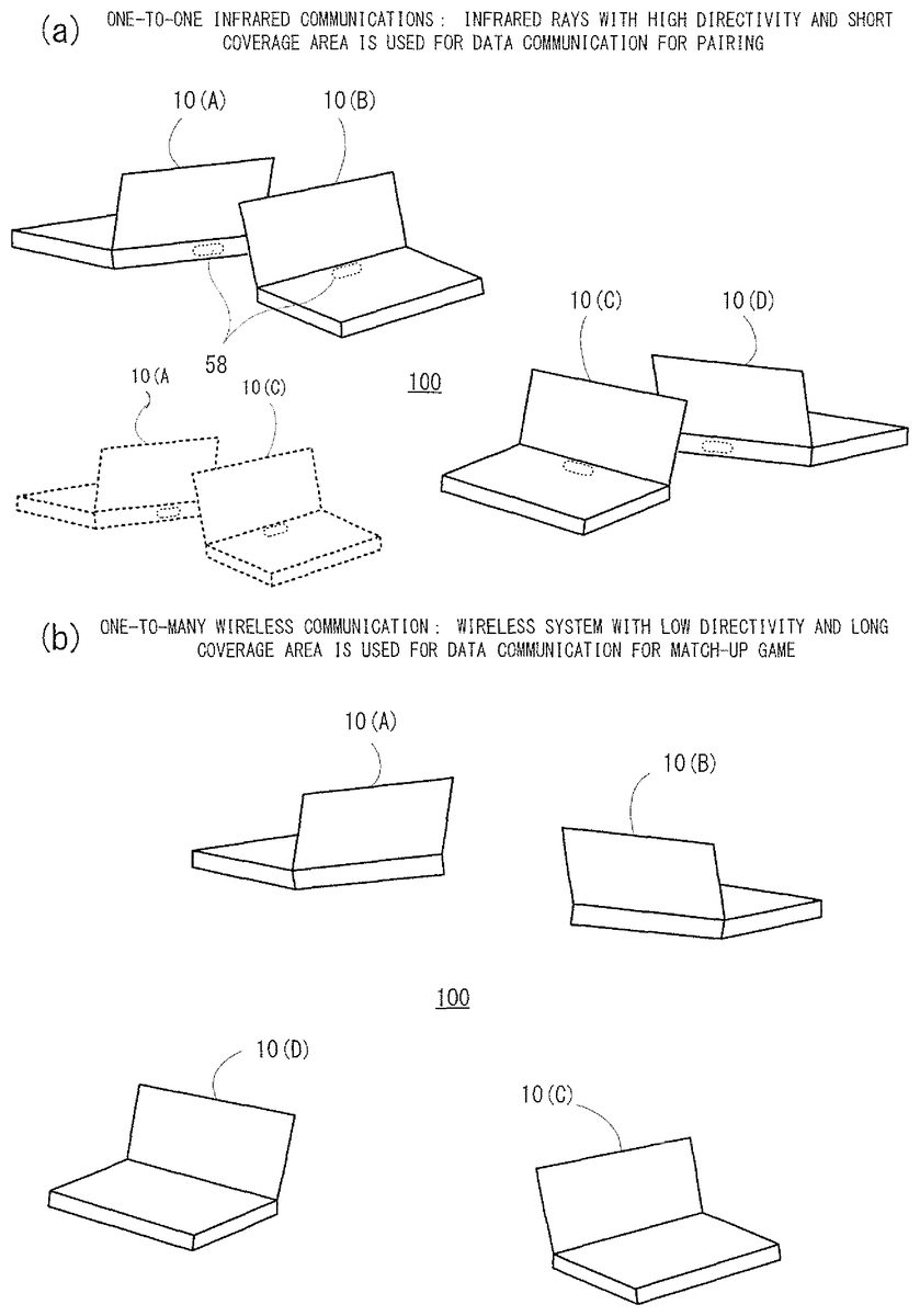
The game apparatus10configured as described consists of a network system100by working together with a plurality of other game apparatuses10each being configured similarly when playing a match-up game. Three or more game apparatuses10which participate in the network system100perform pairings over a one-to-one (described later) infrared communication (seeFIG. 6(a)), make a transition to a one-to-many wireless communication (seeFIG. 6(b)) to play a match-up game by being divided into two or more teams. Alternatively, without being divided into teams, the game apparatuses10may play a match-up game by an individual match. Here, the plurality of game apparatuses10have to be distinguished from one another, they are denoted by game apparatuses10(A),10(B),10(C) . . . . Under certain circumstances, they may be denoted by a master machine A, a slave machine B, a slave machine C or may be abbreviated as A, B, C, . . . .
In what follows, the network system100and an operation of each of the game apparatuses10which participates in the system are explained in detail, but the general outlines of thereof is explained first. Referring toFIG. 6(a) andFIG. 6(b), infrared communications have a property of having a strong (high) directivity and a short coverage area whereas wireless communications have a property of having a weak (low) directivity and a long coverage area. On the other hand, from these properties and communication standards, the infrared communication can be performed without identifying information to identifying each game apparatus10(A),10(B) . . . whereas the wireless communications has a limitation in that it cannot be performed without such identifying information.
Here, the identifying information is typically an MAC address, an IP address, etc., but it may be information defined according to an original rule if the information is the information capable of uniquely specifying each game apparatus10. A user name, a nickname, etc. may be included in the identifying information.
Thereupon, in the network system100, a communication method of first performing pairing via the one-to-one infrared communications and being followed by the one-to-many wireless communications is adopted. More specifically, the plurality of game apparatuses10which participate in the network system100first are divided into arbitrary pairs of game apparatuses, and for each pair, a master and a slave are decided through the one-to-one infrared communications as shown inFIG. 6(a), and the master and the slave notify the identifying information with each other. Such processing is equal to the “pairing” in this embodiment.
Furthermore, when performing the pairing, each game apparatus10writes the identifying information notified from the partner after its own identifying information. Accordingly, at a time of completion of the pairing, in the main memory48(identifying information (ID list) area82: seeFIG. 10) of the game apparatus10which becomes a master, identifying information (B, C . . . , for example) of the game apparatus10which becomes a slave is stored after the self-identifying information (A, for example). The game apparatus10which becomes a slave also stores the identifying information of the game apparatus10which becomes a master after the self-identifying information.
Next, the game apparatuses10which become masters pair with each other again to similarly decide a master and a slave, and they exchange the identifying information between the master and the slave. At this time, the game apparatuses10exchange other identifying information additively written after the self-identifying information with each other. Such processing is repeated until one master game apparatus10remains, and this last game apparatus10is decided as a master machine, and the rest of it are decided as slave machines. In brief, pairings are performed among the plurality of game apparatuses10in the tournament system until one master machine is decided, and in the course of the process, identifying information of respective slave machines are collected in the master machine. Accordingly, the game apparatus10which becomes a master machine through the tournament system consequently stores identifying information (A, B, C . . . ) about all the game apparatuses10.
Additionally, in this embodiment, during the pairing, the identifying information is notified between the master and the slave, but the notification from the master to the slave is not necessarily performed. This is because if the identifying information is notified at least from the slave to the master, all the identifying information is collected to the master machine. In this case, the decision of the master and the slave can be defined as a decision whether a collecting side or not (side of receiving a notification of the identifying information from the partner or a side of notifying the identifying information to the partner).
Furthermore, the number of game apparatuses which participate in the network system100is preferably a power of 2, such as 4 game apparatuses (seeFIG. 8(a)), 8 game apparatuses (seeFIG. 18(a)), etc. by the above-described nature of the tournament. Here, the number except for the power of 2, such as 5 game apparatuses (seeFIG. 17(a)) may be appropriate. If five apparatuses participate, one of them may participate in the second round (seed system).
In addition, the seed system may be adopted irrespective of the number of participating game apparatuses. Although illustration is omitted, when the seed system is adopted in a case the four game apparatuses (A to D) participate, the A and the B are paired (first round), the one which becomes a master, for example, the A is then paired with C (second round), and then, the one which becomes a master, for example, the C is paired with D (third round). The number of pairings to be executed in this case is three times, that is, the times the same as that when the seed system is not adopted (seeFIG. 8(a)), but for the game apparatus10which finally becomes the master machine, pairing is performed at up to three times in a case that the seed system is adopted whereas it needs only two times pairings in a case that the seed system is not adopted.
Generally, irrespective of the tournament table, if the number of participating apparatuses is N, (N−1) pairings are performed until the master machine is decided.
Here, in another embodiment, the identifying information may be exchanged in a round robin system. In the round robin system, when the number of participating apparatuses is N, the number of pairings required for notifying the identifying information among all the game apparatuses10becomes NC2=N·(N−1)/(2·1). Accordingly, if N≧3, it makes possible for the tournament system to make a transition to the wireless communication through the number of pairings less than that in the round robin system.
Next, the game apparatus10which becomes a master machine broadcasts a signal (a so-called beacon) including the identifying information (A, B, C . . . ) possessed by its own apparatus through the one-to-many wireless communication as shown inFIG. 6(b). Each game apparatus10which becomes a slave machine receives the signal thus broadcasted (detects the beacon including the self-identifying information) to thereby acquire the identifying information (A, B, C . . . ) in relation to all the game apparatuses10from the master machine.
Here, since the game apparatus10which becomes a master machine (only master) stores the identifying information of all the communication terminals, and the game apparatus10which becomes a slave stores at least the self-identifying information, for transmission and reception of the signal, a multicast system designating a plurality of destinations may be used, or a unicast system designating a single destination may be individually used, as well as a broadcast system which does not designate a destination.
Since the identifying information (seeFIG. 8(b),FIG. 17(b)) thus collected to the master machine are acquired by additionally writing, after the self-identifying information, the identifying information obtained from the paired partner by the game apparatus10which becomes a master machine in the process of advancing to the final round one after another, depending on which order the identifying information of the respective game apparatuses10are stored, the log of the pairings performed in the tournament can be found. Thereupon, the game apparatus10which becomes a master machine performs a division into the teams based on the pairings according to the storing order of the possessed identifying information (seeFIG. 8(c),FIG. 17(c)). The team information thus obtained is notified to each slave machine by being transmitted so as to be included in a beacon together with identifying information. In the master machine and each slave machine, game processing, such as summing up points is performed on the basis of the team information.
It should be noted that in place of the additively writing manner as described above, a manner in which information indicating a storing order of the identifying information, such as time information and information on the number of pairings, etc. is separately created, and the time information or the number of pairings information is stored together with the identifying information can be used. In this case, the identifying information may be stored in random positions.
Furthermore, the team information may be transmitted at an appropriate timing separately from the identifying information (without being included in the beacon). Alternatively, the team information may be utilized in only the master machine without being notified to the slave machine.
Next, a concrete operating example is explained. First, a case that four (=22) game apparatuses participate (no seed) is explained with reference toFIG. 7-FIG.9.FIG. 7shows one example of a communication sequence,FIG. 8shows one example of pairings in the tournament system, transitions of the ID lists and a division into teams, andFIG. 9shows one example of a screen display updated as the tournament advances, with respect to a case that the four game apparatuses participate.
As described before, the partner to be paired can be decided on the side of the user, and on the lower LCD12of each game apparatus10(A-D), a screen shown inFIG. 9(a) is displayed. Here, on the upper LCD14, an image representing a conception of infrared rays (not illustrated), a scene in which two game apparatuses are close to each other to perform a infrared communication (seeFIG. 6(a)), or the like are displayed.
Assuming that two game apparatuses10(A) and10(B) are face to face with each other to be paired while other two game apparatuses10(C) and10(D) are paired. When the respective pairs are decided, communications over the infrared rays are started, and the one game apparatus makes a connection request to the other game apparatus. Here, in a case that both of the game apparatuses make connection requests, priority is given to the connection request which is first performed, and as to the connection requests which are simultaneously performed, any one of them is selected.
Referring toFIG. 7, with respect to the pair between the A and the B, the game apparatus10(B) transmits a connection request, and the game apparatus10(A) receiving it transmits a response. The game apparatus10(B) becomes a slave at a time when it receives the response from the game apparatus10(A), and transmits an ACK (ACKnowledgement). The game apparatus10(A) becomes a master at a time it receives the ACK from the game apparatus10(B), and transmits the identifying information possessed by its own apparatus (only the A's self-identifying information at this point).
The game apparatus10(B) receives the identifying information thus transmitted from the game apparatus10(A), additively writes the received identifying information after the identifying information possessed by its own apparatus (only the B self-identifying information at this point), and then transmits an ACK. The game apparatus10(A) receiving the ACK transmits an identifying information request, and the game apparatus10(B) receiving it transmits the identifying information possessed by its own apparatus (B's and A's identifying information at this point). Here, when the identifying information is thus transmitted, the identifying information received from the partner (A) may be excluded (the same is true hereunder).
The game apparatus10(A) receives identifying information thus transmitted from the game apparatus10(B), and additively writes the received identifying information after the identifying information possessed by its own apparatus (only the A's self-identifying information at this point). However, in a case that there is identifying information which has been possessed by the game apparatus10(A) before reception, such identifying information (A's self-identifying information has been possessed before the reception) may not be additively written. Through the above-described processing, a pairing between the A and the B is established. With respect to the pair between the C and the D, communications as described above are made, and the C becomes a master, and the D becomes a slave, for example, and they notify the identifying information to each other.
When the pairings (A, B) and (C, D) are thus established, a first round is ended in the tournament table shown inFIG. 8(a), and the A and the C which become the master advance to the pairing at a second round. That is, the screens of the A and the C which becomes the masters at a time of establishment of the pairing are updated as shown inFIG. 9(b), and according to the prompt of the screen, the A and the C are close to and face to face with each other. Then, infrared communications are made between the A and the C similar to the above description, the A becomes a master, the C becomes a slave, for example, and they notify the identifying information to each other. On the other hand, the screens of the B and the D which become the slaves through the pairing at the first round are updated as shown inFIG. 9(c), and the B and the D are waited according to the prompt of the screen.
When the pairing (A, C) is thus established, the second round is ended in the tournament table shown inFIG. 8(a). The A which is the only master at this point becomes the master machine and the B-D which are slaves become slave machines. Here, the screen of the C is updated as shown inFIG. 9(c) similar to the B and the D. Furthermore, the screen of the A which becomes the only master is also updated as shown inFIG. 9(c).
Furthermore, as the tournament advances, the identifying information (ID list) possessed by the A-D make a transition as shown inFIG. 8(b). That is, in each of the ID lists of the A to D, in the initial state, self-identifying information, that is, only the “A”, the “B”, the “C”, or the “D” is stored. After the first round, identifying information of the partner to be paired is additively written after the self-identifying information, so that each of the identifying information makes transitions to “A, B”, “B, A”, “C, D”, and “D, C”. After the second round, the ID lists of the A and the C are further changed as shown in “A, B, C, D”, and “C, D, A, B”, respectively. Here, if only the notification from the slave to the master is performed, the ID lists of the B and the D are left in the initial state, and the ID list of the C is in a state after the first round, that is, maintains the “C, D”.
Additionally, inFIG. 8(b),FIG. 17(b), andFIG. 18(a), numerals1,2, . . . are given to the respective slave machines, but this numerals show a describing order (chronologically) in the ID list of the master machine, and can be used as priority information, for example, in the later game processing.
Then, from the ID list of the A as a master machine, that is, from the “A, B, C, D”, team information, that is, “(A, B)/(C, D)” shown inFIG. 8(c) is created. The team information can be obtained by dividing the “A, B, C, D” to half, that is, the first half and the second half, and corresponds to the pairings in the first round of the tournament.
Returning toFIG. 7, the A which becomes a master machine broadcasts a beacon including the ID list possessed by it own machine, that is, “A, B, C, D” and the team information“(A, B)/(C, D)”. The B to D which become slave machines can acquire the identifying information and the team information which are required to perform a match-up game among the A to D through the one-to-many wireless communication by detecting the beacon including the self-identifying information thus broadcasted from the master machine. The ID lists possessed by the B to D are overwritten with the ID list received from the A. At this point, the screens of the A to D are updated to the screen shown inFIG. 9(d).
Here, on the screen shown inFIG. 9(d), the identifying information and the team information of the A to the D may be displayed. The identifying information to be displayed here is preferably a user name, a nickname, etc. Furthermore, on the upper LCD14, an image representing a conception of the wireless communication (not illustrated), or a scene in which four game apparatuses make wireless communications far from one another (seeFIG. 6(b)) is displayed.
From each of the B to D receiving the beacon, a response is transmitted to the A. The match-up game (A, B) team versus (C, D) team is started after the A receives the responses from B to D. In the match-up game, the score is sum up on the basis of the team information for each team, and a winning team or a team standing is decided by scores.
The operation as described above is implemented by executing processing according to a flowchart shown inFIG. 11toFIG. 16by the CPU42of each game apparatus10on the basis of the programs and data as shown inFIG. 10that are stored in the main memory48. That is, when the match-up game in this embodiment is performed, the main memory48is formed with a program area48aand a data area48bas shown inFIG. 10. In the program are48a, a game program70, an input-output controlling program72, an infrared communication controlling program74, a wireless communication controlling program76, etc. are stored.
The game program70is a software program for implementing a match-up game by controlling various pieces of hardware (12-40,44-60) via the CPU42, and the part (until pairings via the infrared rays are made and then, the wireless communication is established) corresponds the flowchart shown inFIG. 11-FIG.16. Additionally, the game program70is attached with a game ID indicating the kind of the game (title, version, etc.).
The input-output controlling program72is a sub software program to be used by the game program70, and implements an image output, a button input, a touch input, etc. by controlling mainly the lower LCD12, the operating portion24, the I/F circuit40, etc. The infrared communication controlling program74is a subprogram to be used by the game program70, and implements infrared communications with other game apparatuses10by controlling mainly the local (infrared rays) communication module58. The wireless communication controlling program76is a subprogram to be used by the game program70, and implements wireless communications with other game apparatuses10by controlling mainly the wireless communication module56.
The data area48bincludes a parameter area78, a variable area80, an identifying information (ID list) area82, a team information area84, a drawing data area86, etc. In the parameter area78, parameters to be referred by the game program70, such as the number of participants (four), the maximum number of retries (five times) are stored. Here, the values of the parameters can be suitably changed from a menu selection screen, etc. not shown. In the variable area80, variables to be controlled by the game program70, such as the number of pairings, the number of retries, a master-and-slave flag are stored.
In the identifying information (ID list) area82, the self-identifying information like “A” is stored in the initial state, then, each pairing via the infrared rays, the identifying information of the partner is additively written in order, and at a time a wireless communication is established, identifying information of all the game apparatuses10like “A, B, C, D” are stored. In the team information area82, team information created by such identifying information like “(A, B)/(C, D)” is stored. In the drawing data area86, data for drawing the screens shown inFIG. 9(a)-FIG. 9(d), for example, is stored.
Now, when the menu selection screen not shown is displayed on the lower LCD12, and the “match-up game” as one option is selected with the touch panel28, the CPU42starts processing according to the flowchart shown inFIG. 11-FIG.16. The CPU42updates the screen of the lower LCD12as shown inFIG. 9(a) in a step S1inFIG. 11. On the screen inFIG. 9(a), a prompt saying that “THIS IS FOUR-PERSON-MATCH-UP GAME . . . PLEASE DIRECT INFRARED RAYS TOWARD PARTNER TO BE PAIRED” is included. Then, in a step S2, the number of pairings being one of the variables stored in the variable area80is reset (the number of pairings=0), and in a step S3, the number of retries being one of the variables is reset as well (the number of retries=0).
Next, the CPU42proceeds to a step S5to transmit a connection request via infrared rays. The transmission of the connection request may be performed on the basis of an instruction from the user, or may be automatically performed independent from the user's instruction. Here, the signal transmitted via the infrared rays (connection request, response, ACK, etc.: seeFIG. 7) is directed to an unspecific partner, and can be transmitted without the identifying information (destination) of the partner. In a next step S7, it is determined whether or not a signal is received via the infrared rays, and if “NO” here, the process shifts to a step S9to further determine whether or not a not-yet-received state (the determination result in the step S7is “NO”) continues for a predetermined time (10 seconds, for example) or more. If “NO” here, the process returns to the step S7. If “YES” in the step S7, the kind of signal is determined through steps S15and S17, and the processing corresponding to the determination result (described later) is executed.
If “YES” in the step S9, the process proceeds to a step S11to determine whether or not the number of retries reaches a predetermined number of times (More specifically, the maximum number of retries being one of the parameters stored in the parameter area78: 5 times). If “YES” in the step S11, the process is ended whereas if “NO”, after a wait for a time randomly decided in a step S13, the process returns to the step S5. During this time, that is, during the wait in the step S13, the number of retries is incremented.
Accordingly, if the positional relationship between the game apparatus10(A) and the game apparatus10(B) of the partner is not proper (both apparatuses are so far away from each other, there is no partner, an orientation of the infrared rays is widely displaced), a connection via the infrared rays is not established, and a retry is executed at random time intervals. If a connection is not established even after the five retries, the processing is ended. At this time, an error display showing that a connection is not established may be displayed on the screen. In such a case, the “match-up game” is newly selected on the menu selection screen to thereby restart the processing.
Here, the waiting time in the step S13is decided every time by utilizing the random numbers by the CPU42, for example. Or, the waiting times corresponding to the number of retries may be decided in advance, such as 5 seconds in a case that the number of retries is 0, and 4 seconds in a case that the number of retries is 1.
In a step S15inFIG. 12, it is determined whether or not the received signal is a connection request, and if “YES” here, processing from steps S19to S57being processing for a master is executed, and then the process shifts to the game processing or the process is ended. If “NO” in the step S15, the process shifts to the step S17to determine whether or not the received signal is a response, and if “YES” here, processing from steps S59to S89being processing for a slave is executed, and then the processing shifts to the game processing or the processing is ended. If “NO” in the step S17as well, the process returns to the step S11. Accordingly, if the received signal is neither the connection request nor the response, the signal is regarded as not being received, and a retry is performed after the number of retries is checked and incremented.
The processing for a master is executed in details below. That is, after “YES” is determined in the step S15, in response to the received signal, that is, the connection request, a response is transmitted via the infrared rays in the first step S19, and it is determined whether or not an ACK is received via the infrared rays in the next step S21. If “NO” in the step S21, the process shifts to the step S23to determine whether or not a not-yet-received state (the determination result in the step S21is “NO”) continues for a predetermined time (10 seconds, for example) or more, and if “NO” here, the process returns to the step S21. If “YES” in the step S23, the process returns to the step S11. Accordingly, if there is no ACK in response to the transmitted response as well, a retry is performed after the number of retries is checked and incremented.
If “YES” in the step S21, by controlling the master-and-slave flag being one of the variables, its own apparatus is regarded as a master in the step S25, and then, the process proceeds to the step S27shown inFIG. 13to transmits via the infrared rays a signal indicating all the identifying information possessed by its own apparatus, that is, a signal indicating the content of the identifying information (ID list) area82.
Here, after the step S25, the step S26aand the step S26bmay be executed before the process proceeds to the step S27. This will be explained below.
In the following step S29, it is determined whether or not an ACK is received via the infrared rays, and if “NO” here, the process shifts to the step S31to determine whether or not a not-yet-received state (the determination result in the step S29is “NO”) continues for a predetermined time (10 seconds, for example) or more, and if “NO” here as well, the process returns to the step S29. If “YES” in the step S31, the process returns to the step S11. Accordingly, if there is no ACK in response to the transmitted identifying information as well, a retry is performed after the number of retries is checked and incremented.
If “YES” in the step S29, the process proceeds to the step S33to transmit a identifying information request via the infrared rays. In the following step S35, it is determined whether or not the identifying information is received via the infrared rays, and if “NO” here, the process shifts to the step S37to determine whether or not a not-yet-received state (the determination result in the step S35is “NO”) continues for a predetermined time (10 seconds, for example) or more. If “NO” here as well, the process returns to the step S35. If “YES” in the step S37, the process returns to the step S11. Accordingly, if no identifying information is sent in response to the identifying information request, a retry is performed after the number of retries is checked and incremented.
If “YES” in the step S35, the process proceeds to the step S39to additively write the received identifying information after the identifying information possessed by its own game apparatus in order. Here, if the identifying information containing the identifying information which has transmitted to the partner by it own machine is transmitted, processing of removing the redundant is required at a time of additive writing. Alternatively, in such a situation, the identifying information may not be additively written, but may be overwritten. However, in a case that the overwriting is performed, the order of the identifying information is equal to the order of the identifying information possessed by the communication partner, that is, the game apparatus10as a slave, so that the method of dividing into teams according to the order of the identifying information may not be performed effectively.
Then, in the step S40, the number of pairings is incremented, and then, the process proceeds to the step S41shown inFIG. 14to determine whether or not the number of pairings reaches a predetermined number of times (two times because the number of participating game apparatuses is 4). Here, the determination is equivalent to the determination whether or not identifying information is collected by the number of participating game apparatuses (4 here). In this case, how many identifying information of the game apparatuses is stored in the identifying information (ID list) area82is specifically detected, and if the detected number reaches the number of participating game apparatuses, that is, 4 apparatuses, “YES” is determined, and if it is equal to or less than 3 apparatuses, “NO” may be determined. If “NO” in the step S41, the process shifts to the step S43to update the screen of the lower LCD12as shown inFIG. 9(b). On the screen inFIG. 9(b), a prompt saying that “YOU BECOME LEADER . . . DIRECT INFRARED RAYS TOWARD LEADER OF PARTNER PAIR” is included. Thereafter, the process returns to the step S3to repeat similar processing. That is, after the number of retries is reset, a pairing with the next partner is performed.
Additionally, in the step S41inFIG. 14, when the number of pairings reaches a predetermined number of times, or when the number of detected game apparatuses reaches the number of participating game apparatuses, it is determined that the identifying information are collected, but if the number of times its own game apparatus becomes a master is counted, and the result reaches the predetermined number of times, it can be determined that its own game apparatus becomes the only master (eventually, identifying information are collected). Alternatively, when a predetermined operation is performed via the touch panel28, etc., it may be regarded that its own game apparatus becomes the only master.
If “YES” in the step S41, the process proceeds to the step S45to divide the game apparatuses into teams for the match-up game on the basis of the identifying information (ID lists) of the four game apparatuses stored in the identifying information (ID list) area82. Although the explanation by a flowchart is omitted, in the subroutine, processing of dividing the ID list “A, B, C, D” into halves as shown inFIG. 8(c) is performed, and this makes it possible to obtain team information “(A, B)/(C, D)” on which the pairings in the tournament as shown inFIG. 8(a) are reflected. However, depending on the number of participating game apparatuses or the procedure of the pairing, the game apparatuses are unequally divided as shown inFIG. 17(c) or divided into three or more as shown inFIG. 18(b).
The CPU42switches from an infrared rays communication manner to a wireless communication manner by stopping the local communication module58and activating the wireless communication module56. In the next step S49, the CPU42broadcasts a signal (beacon) including all the identifying information, that is, the identifying information by the number of participating game apparatuses (“A, B, C, D”, for example) stored in the identifying information (ID list) area82and the team information (“(A, B)/(C, D)”, for example) stored in the team information area84, and waits for a response in response to the beacon. Then, in the step S51, it is determined whether or not a response is received within a predetermined time (10 seconds, for example) from each of all the slaves (B, C, D, for example) wirelessly.
If there is even one slave which does not respond wirelessly after a lapse of predetermined times from the broad cast, “NO” is determined in the step S51, error processing is executed in the step S53, then, the processing is ended. The error processing includes processing of displaying a message saying that an error occurs, and processing of broadcasting again. Alternatively, when a predetermined time elapses, even if not all the slaves respond, but there is at least one slave which responds, a data communication may be started with only the responding slave in the step S55described later. In this case, the team information has to be changed, so that the master may divide only the responding slaves and may transmit again new team information via the established wireless communication.
If there are responses from all the slaves wirelessly before a lapse of the predetermined times, the process proceeds from the step S51to the step S55to start data communications with each slave machine (B, C, D, for example) wirelessly as a master machine, so that from this point, the four game apparatuses (A to D) work together to execute the game processing with the master machine A being the center. Then, the process proceeds to the step S57(described later).
On the other hand, the processing as a slave is executed as described below in detail. That is, inFIG. 12, After “YES” is determined in the step S17, in the first step S59, an ACK in response to the received signal, that is, the response is transmitted via the infrared rays, and in the next step S61, the master-and-slave flag is controlled to regard its own game apparatus as a slave. Then, the process proceeds to the step S63shown inFIG. 15to determine whether or not the identifying information is received via the infrared rays. If “NO” here, the process shifts to the step S65to further determine whether or not a not-yet-received state (determination result in the step S63is “NO”) continues for a predetermined time (10 seconds, for example), and if “NO” here as well, the process returns to the step S63. If “YES” in the step S65, the process returns to the step S11. Accordingly, even if the ACK is transmitted, but the identifying information is sent back as well, a retry is performed after the number of retries is checked and incremented.
Here, the step S62aand the step S62bmay be executed between the step S61and the step S63. This may be explained later.
If “YES” in the step S63, the process proceeds to the step S67to write the received identifying information after the identifying information possessed by its own machine. In the next step S69, an ACK is transmitted via the infrared rays, and in the step S71, it is determined whether or not the identifying information is received via the infrared rays. If “NO” here, the process shifts to the step S73to further determine whether or no a not-yet-received state (the determination result in the step S71is “NO”) continues for a predetermined time (10 seconds, for example) or more, if “NO” here as well, the process returns to the step S71. If “YES” in the step S73, the process returns to the step S11. Accordingly, even if the ACK is transmitted, but an identifying information request is not sent back as well, a retry is performed after the number of retries is checked and incremented.
If “YES” in the step S71, the process proceeds to the step S75to transmit a signal indicating all the identifying information possessed by its own machine, that is, a signal indicating the contents of the identifying information (ID list) area82via the infrared rays. Here, the identifying information received from the partner in the step S63may not be included. In the next step S77, the screen on the lower LCD12is updated as shown inFIG. 9(c). On the screen shown inFIG. 9(c), a prompt, such as “PLEASE WAIT FOR MOMENT . . . ” is included. Succeedingly, in the step S79, by stopping the local communication module58and activating the wireless communication module56, the communication system is switched from the infrared rays communication to the wireless communication.
Next, the process proceeds to the step S80inFIG. 16to determine whether or not the signal (beacon) is received wirelessly. If “NO” here, the process shifts to the step S83to determine whether or not a not-yet-received state (determination result in the step S80is “NO”) continues for a predetermined time (10 seconds) or more, and if “NO” here, the process returns to the step S80. If “YES” in the step S80, the process proceeds to the step S81to further determine whether or not the signal includes the self-identifying information, and if “NO” in the step S81, it is regarded that the signal is not received, and the process shifts to the step S83.
If “YES” in the step S83, error processing is executed in the step S89, and then, the processing is ended. In the error processing, processing of displaying a message saying that an error occurs, for example, is included. Before a lapse of the predetermined times, if the beacon including the self-identifying information is detected, the process proceeds from the step S81to the step S85to transmit a response wirelessly on the basis of the identifying information of the master included in the beacon. Then, in the step S87, data communications as a slave machine are started with the master machine wirelessly, and from this point, the four game apparatuses (A to D) work together to execute game processing with the master machine A being the center from this time.
In the step S87or in the step S57successive to the above-described step S55, the screen of the lower LCD12is updated as shown inFIG. 9(e). On the screen shown inFIG. 9(e), a prompt “MATCH-UP GAME IS STARETED . . . YOU MAY BE APART FROM FRIEND” is included. The processing by the CPU42shifts to the game processing not shown.
In the operation example, when the master and the slave are decided (S25&S61: seeFIG. 12), transmission and reception of the identifying information is immediately started via the infrared rays (S27&S63:FIG. 13, seeFIG. 15), but this may be started after the game IDs (seeFIG. 10) match between the master and the slave. More specifically, after the master and the slave are decided in the steps S25and S61, in the steps S26aand S62a, the game IDs are exchanged between the master and the slave, and it is determined whether or not both of the game IDs match in the steps S26band S62b. Then, if the game IDs match with each other, the process proceeds to the steps S27and S63to start transmission and reception of the identifying information, and if the IDs do not match with each other, the process is ended after the error processing in the step S26c. In the error processing, processing of notifying that the each other's game IDs do not mach is included. Thus, if the each other's game apparatuses are different in kind and versions, or the like of the match-up game, by confirming the each other's game IDs immediately after the connection over the infrared rays is established, it is possible to inform the user of the mismatch at timing as soon as possible.
Next, one example when the number of participating game apparatuses is different from the power of 2 is shown by usingFIG. 17. InFIG. 17, one example of pairings by the tournament system, transitions of the ID lists and a division into teams when five game apparatuses participate are illustrated. Here, since the communication sequence is basically the same as that when the four game apparatuses participate as shown inFIG. 7(a set of one-to-one infrared communication is merely added), the illustration and detailed explanation are omitted. The flowchart is also omitted because of being the same asFIG. 11-FIG.16.
Here, the A and the B are paired, and the C and the D are paired. The E has no partner at this point, that is, at a first round. The A and the B in a pair make infrared communications, the A becomes a master for example, and then, they notify the identifying information with each other. The C and D in a pair make an infrared communication, the C, for example, becomes the master, and then, they notify the identifying information with each other. When the pairings, such as (A, B) and (C, D), are established, the first round is ended in the tournament table shown inFIG. 17(a). At this time, the ID lists of A-E are a state after the first round in the second line shown inFIG. 17(b).
Next, the E seeded at the first round newly pairs with one of the C and D in a pair which becomes a master, that is, the C. The C and E in a pair make infrared communications, the E becomes a master, for example, and they notify the identifying information with each other. When the pairing (C, E) is thus established, the second round is ended in the tournament table shown inFIG. 17(a). At this time, the ID lists of the A to E is a state after the second round in the third line shown inFIG. 17(b).
Next, one out of the C and the E which becomes a master, that is, the E newly pairs with one out of the A and the B which becomes a master, that is, A. The A and E in a pair make infrared communications, the E becomes a master, for example, and they notify the identifying information with each other. When the pairing such as (A, E) is thus established, the third round is ended in the tournament table shown inFIG. 17(a). At this point, the ID lists of the A to E is a state after the third round in the forth line shown inFIG. 17(b). Then, the only master E becomes a master machine, and the A to D become slave machines.
Next, from the ID list of the E being the master machine, that is, “E, C, D, A, B”, team information shown inFIG. 17(c), that is, “(E, C, D)/(A, B)” is produced. The team information is obtained by dividing “E, C, D, A, B” into 3:2, that is, the first half and the second half, and corresponds to the pairings at the first and second rounds in the tournament.
Alternatively, another example when the number of participating game apparatuses is the power of 2 is explained with reference toFIG. 18.FIG. 18shows one example of pairings in the tournament system and a division into teams when 8 (=23) game apparatuses participate. Here, since the communication sequence is basically the same as that when the four game apparatuses participate as shown inFIG. 7(four sets of one-to-one infrared communications are merely added), the illustration and detailed explanation are omitted. The flowchart is also omitted because of being the same asFIG. 11-FIG.16.
In the tournament shown inFIG. 18(a), pairings (A, B), (C, D), (E, F) and (G, H) are established at the first round, pairings (A, C) and (F, G) are established at the second round, and a (A, G) pairing is established at the third round. At a time of completion of the third round, the only master A becomes the master machine whereas the B to H all become slave machines.
From this procedure, as shown inFIG. 18(b), the ID list of the A being the master machine becomes “A, B, C, D, G, H, F, E”, and by dividing it to halves, “(A, B, C, D)/(G, H, F, E)” can be obtained as team information. This corresponds to the pairings at the first round and the second round in the tournament.
Alternatively, if the match-up game is played in divided four teams, by dividing the ID list into four, “(A, B)/(C, D)/(G, H)/(F, E)” can be obtained. This corresponds to the pairings at the first round in the tournament.
It should be noted that in each of the above-described operation examples, the number of participating game apparatuses is fixed to 4, 5 or 8 apparatuses, but it may be configured to be selected by the user from some options (2, 4 and 8 apparatuses, for example). Alternatively, within a predetermined range (2-8 apparatuses, for example), the user may designate the arbitrary number (5 apparatuses, for example).
As understood from the above description, in this embodiment, the network system100is made up of three or more game apparatuses10(A),10(B),10(C) . . . each storing at least self-identifying information (A, B, C . . . ). Each game apparatus10(A, for example) has the wireless communication module56and the local communication module58. The wireless communication module56makes it possible to make a one-to-many wireless communication between its own game apparatus and the plurality of game apparatuses10(B),10(C) . . . except for its own game apparatus with reference to each of the identifying information (A, B, C . . . ). The local communication module58makes it possible to make a one-to-one communication between its own game apparatus and each game apparatus10(B),10(C) other than its own game apparatus without reference to each identifying information (A, B, C, . . . ).
The game apparatus10(A) stores the identifying information (A) of its own game apparatus (10(A)), but does not always store the identifying information (B, C . . . ) of the game apparatus10(B),10(C) . . . other than its own game apparatus (10(A)). Thus, if a wireless communication is performed by the wireless communication module56, the CPU42executes pairing processing of first deciding a master and a slave together with any one game apparatus10(B, for example) out of the other game apparatuses other than its own game apparatus (10(A)) via the local communication module58, collecting the identifying information stored in the slave side to the master side, and executes next pairing processing with another game apparatus10(C, for example) if its own game apparatus becomes the master, and waits in a case that its own game apparatus becomes the slave (S1-S43, S59-S77). Next, if its own game apparatus (10(A)) becomes the only master as a result of a series of pairing processing, its own game apparatus transmits a signal (beacon, for example) including the identifying information (A, B, C . . . ) of all the game apparatuses10(A),10(B),10(C) . . . including its own game apparatus (10(A)) via the wireless communication module56whereas if its own game apparatus (10(A)) becomes a slave, it receives the signal transmitted from the only master via the wireless communication module56(S49-S53, S80-S89). Accordingly, the identifying information (A, B, C . . . ) of all the game apparatuses10(A),10(B),10(C) . . . are collected to the game apparatus10(A) which becomes a master through a series of pairings, that is, the master machine A, and the game apparatuses10(B),10(C) which become slaves through the series of pairings . . . , that is, each slave machine B, C, . . . can receive delivery of the identifying information (A, B, C . . . ) from the master machine A.
Thus, the three or more game apparatuses10(A),10(B),10(C) . . . , each storing only the self-identifying information, can perform pairings by the local communication module58, and followed by the one-to-many wireless communication by the wireless communication module56to thereby execute the match-up game processing. Furthermore, a tournament system in which only the game apparatus10which currently becomes a master can advance to a next pairing is adopted, so that the number of pairing processing can be made less than that of the a round robin system in which each communication terminal makes a pairing with all the communication terminal except for its own communication terminal, capable of making a transition from the local communications (infrared rays) to the wireless communications.
Furthermore, in the game apparatus10(A), the identifying information (A) of its own game apparatus (10(A)) is stored in the identifying information area82of the main memory48, and the CPU42collects by additively writing the identifying information (B, C . . . ) notified from the partner in the series of pairing processing in the identifying information area82one after another (S39). Then, in a case that its own game apparatus (10(A)) becomes the only master, the respective game apparatuses10(A),10(B) are divided into teams on the basis of the order of the identifying information stored in the identifying information area82(S45), and the match-up game processing is executed on the basis of the result (team information). This makes it possible to perform a division into teams on which the pairings in the tournament are reflected.
In this embodiment, the team information is created from the identifying information (ID lists) collected through the tournament, but in place of the team information, or in addition thereto, priority information may be created. For example, in the example shown inFIG. 8(c), a describing order of the ID lists “A, B, C, D” can be utilized as priority information as it is. Or, if a high priority is assigned to the first and the third IDs in the ID list, and a low priority is assigned to the second and the fourth IDs in the ID list, the former indicates the A and C which advance to the second round of the tournament, and the latter indicates the B and D which become the slaves at the first round of the pairing. The pairings in the tournament is also reflected on such the priority information to be utilized in the match-up game. Example is that the terminal having a higher priority can use a specific item.
Furthermore, in this embodiment, infrared rays system for a data communication for pairing is used, but other wireless communication systems, if they have a high directivity and/or short coverage area, such as systems to be utilized contactless integrated circuit cards, for example, may be used. In other words, any systems having a narrow coverage area, and allowing only a desired partner to be guided into the coverage area without a multiplicity of unspecific partners from being entered into the coverage area can perform pairings as described above. In addition, if only it can make a communication only with a desired partner out of a plurality of participants, the communication system is not required to be the wireless system, and may be a one-to-one wired system connecting a pair of two game apparatuses10by cable.
In addition, in this embodiment, as a deciding method of the master and the slave, a side receiving a connection response becomes a slave, and a side receiving an ACK in response to a connection response becomes a master, but this is not restricted to this method. A method of randomly making one game apparatus10a master in pairing and making the other game apparatus10a slave, or a method of allowing a user to select between a master and a slave in pairing may be adopted.
On the other hand, for a data communication for the match-up game, a wireless LAN system according to an original protocol on the IEEE802.11 standards to be performed between one master machine and a plurality of slave machines is utilized, but any system, if they have a weaker directivity and a longer coverage area than that of the infrared rays systems (coverage area having a radius of about several meters or more, for example), other wireless communication systems may be utilized. Typically, Bluetooth, ZigBee (both are registered trademark: The communication allowable range is 10 m-100 m) are enumerated.
In the above description, an explanation is made on the game apparatus10, but this invention can be applied to communication terminals (a cellular phone, a PC, a PDA other than the game apparatus, for example) having a first communication module making a one-to-many wireless communication between its own communication terminal and a plurality of communication terminals other than itself with reference to the identifying information, a second communication module making a one-to-one communication between its own communication terminal and the plurality of communication terminals other than itself without reference to the identifying information, and a computer (CPU).
Although the present invention has been described and illustrated in detail, it is clearly understood that the same is by way of illustration and example only and is not to be taken by way of limitation, the spirit and scope of the present invention being limited only by the terms of the appended claims.
Claims
- A network system including first, second and third communication terminals each storing at least self-identifying information, wherein said first communication terminal comprises a first communication module for making a wireless communication with said second and third communication terminals with reference to their identifying information, a second communication module for making a communication with each of said second and third communication terminals without reference to said identifying information, a pairing unit which executes paring processing of storing and collecting, with said second communication terminal, the identifying information stored in one of said first and second communication terminals into the other of said first and second communication terminals via said second communication module prior to a start of a wireless communication by said first communication module, and further executes next pairing processing of storing and collecting, with said third communication terminal, the identifying information stored in one of said first and third communication terminals into the other of said first and third communication terminals when a first condition requiring that a collection from said second communication terminal to said first communication terminal is done is satisfied in said pairing processing, and a signal transmitting and receiving unit which transmits a signal including all the collected identifying information to said second and third communication terminals via said first communication module when a second condition requiring that collections from said second and third communication terminals to said first communication terminal are done is satisfied and receives said signal transmitted from said second and/or third communication terminal via said first communication module when a third condition is satisfied, as a result of a series of said pairing processing by said pairing unit.
- A network system according to claim 1 , wherein said first communication module has a coverage area wider than that of said second communication module.
- A network system according to claim 1 , wherein said second communication module has a directivity higher than that of said first communication module.
- A network system according to claim 1 , wherein said first communication terminal waits until a signal from said second and third communication terminals is received via said first communication module when said third condition is satisfied as a result of said pairing processing.
- A network system according to claim 1 , wherein said first condition is that the identifying information stored in said other of said first and third communication terminals is stored and collected into its own communication terminal in said pairing processing.
- A network system according to claim 1 , wherein said communication terminal further comprises a connection request transmitting unit for transmitting a connection request to said second and third communication terminals via said second communication module, and a connection request receiving unit for receiving a connection request from said second and third communication terminals via said second communication module, and said first condition is that said connection request is received.
- A network system according to claim 1 , wherein said communication terminal further comprises a counting unit for counting the number of pairing processing of storing and collecting the identifying information stored in said second and third communication terminal into its own communication terminal, and said second condition further requires that the count by said counting unit reaches a predetermined number of times.
- A network system according to claim 1 , wherein said third condition is satisfied when the identifying information stored in said first communication terminal is stored and collected into said second and third communication terminals in said pairing processing.
- A network system according to claim 1 , wherein said first communication terminal further comprises a collecting-side-communication-terminal deciding unit for deciding whether or not said first communication terminal is to become a communication terminal on a collecting side in a communication with any of said first and second communication terminals, and said pairing unit stores and collects the identifying information stored in said second and third communication terminals into said first communication terminal when said collecting-side-communication-terminal deciding unit decides that said first communication terminal is to become the communication terminal on the collecting side.
- A network system according to claim 9 , wherein said first condition is satisfied when said collecting-side-communication-terminal deciding unit decides that said first communication terminal is to become the communication terminal on the collecting side.
- A network system according to claim 9 , wherein said third condition is satisfied when said collecting-side-communication-terminal deciding unit decides that said first communication terminal does not become the communication terminal on the collecting side.
- A network system according to claim 1 , wherein said first communication terminal further comprises a master-and-slave deciding unit for deciding whether said first communication terminal is to become a master or a slave in a communication with any one of said second or third communication terminals, said pairing unit stores and collects the identifying information stored in said second and third communication terminals into said first communication terminal when said first communication terminal becomes the master by said master-and-slave deciding unit, and stores and collects the identifying information stored in said first communication terminal into said second and third communication terminals when said first communication terminal becomes the slave by said master-and-slave deciding unit.
- A network system according to claim 12 , wherein said first communication terminal further comprises a connection request transmitting unit for transmitting a connection request to said second and/or third communication terminals via said second communication module, a connection request receiving unit for receiving said connection request from said second and/or third communication terminal via said second communication module, a connection response transmitting unit for transmitting via said second communication module a connection response to said second and/or third communication terminal which has transmitted said connection request when said connection request is received and a connection response receiving unit for receiving said connection response from said second and/or third communication terminal via said second communication module, and said master-and-slave deciding unit decides that said first communication terminal becomes a master when it receives said connection request, and decides that said first communication terminal becomes a slave when it receives said connection response.
- A network system according to claim 1 , wherein said first communication terminal further comprises an identifying information transmitting unit for transmitting the stored identifying information to said second and third communication terminals and an identifying information receiving unit for receiving the identifying information stored in said second and third communication terminal, and said pairing unit stores and collects the identifying information into said first communication terminal when the identifying information stored in said second and third communication terminal is received by said identifying information receiving unit, and collects the identifying information into said second and third communication terminal when the identifying information is transmitted to said second and third communication terminal by said identifying information transmitting unit, said first condition is satisfied when the identifying information stored in said second or third communication terminal is received by said identifying information receiving unit, and said third condition is satisfied when the identifying information is transmitted to said second and third communication terminal by said identifying information transmitting unit.
- A network system according to claim 1 , wherein a partner to be subjected to next pairing processing with said first communication terminal for which said first condition has been satisfied in said pairing processing is said second and/or third communication terminal for which said first condition has been satisfied in another pairing processing.
- A network system according to claim 1 , wherein said first communication terminal further comprises a memory storing self-identifying information, and said pairing unit collects by additively writing the identifying information in order in said memory through a series of pairing processing.
- A network system according to claim 1 , wherein said first communication terminal further comprises a processing unit for starting a wireless communication by said first communication module with reference to the identifying information sent or received by said signal transmitting and receiving unit, and executing information processing by operation of said first communication terminal together with each of said second and third communication terminals.
- A network system according to claim 16 , wherein said first communication terminal further comprises a dividing unit for dividing said first, second and third communication terminal into teams on a basis of an order of the identifying information stored in said memory when said second condition is satisfied, and a processing unit for starting a wireless communication by said first communication module after the transmission or the reception by said signal transmitting and receiving unit, and executing game processing in such a manner as to divide said communication terminals into teams by utilizing a result of said dividing unit to thereby battle between said first communication terminal and said second and third communication terminals.
- A network system according to claim 1 , wherein said first communication terminal further comprises a self-identifying-information determining unit for determining whether or not the self-identifying information is included in said signal when said signal is received by said signal transmitting and receiving unit, and a processing unit for starting a wireless communication with said second and third communication terminal for which said second condition is satisfied via said first communication module with reference to said signal, and executing information processing when said self-identifying-information determining unit determines that the self-identifying information is included in said signal.
- A first communication terminal storing at least self-identifying information, comprising: a first communication module for making a wireless communication with second and third communication terminals with reference to their identifying information;a second communication module for making a communication with said second and third communication terminals without reference to said identifying information;a pairing unit for executing a pairing processing of storing and collecting with said second communication terminal the identifying information stored in one of said first and second terminals communication into the other of said first and second terminals communication via said second communication module prior to a start of a wireless communication by said first communication module, and further executes next pairing processing of storing and collecting, with said third communication terminal, the identifying information stored in one of said first and second communication terminal into the other of said first and third communication terminals when a first condition requiring that a collection from said second communication terminal to said first communication terminal is done is satisfied in said pairing processing;and a signal transmitting and receiving unit which transmits a signal including all the collected identifying information to said second and third communication terminals via said first communication module when a second condition requiring that collections from said second and third communication terminals to said first communication terminal are done is satisfied and receives said signal transmitted from said second and/or third communication terminal via said first communication module when a third condition is satisfied, as a result of a series of said pairing processing by said pairing unit.
- A non-transitory storage medium storing a communication program, wherein said communication program causes a computer of a first communication terminal storing at least its own identifying information and having a first communication module for making a wireless communication with second and third communication terminals with reference to identifying information for said second and third communication terminals, and a second communication module for making a communication with said second and third communication terminals without reference to said identifying information, to function as a pairing unit for executing a pairing processing of storing and collecting with said second communication terminal the identifying information stored in one of said first and second terminals communication into the other of said first and second terminals communication via said second communication module prior to a start of a wireless communication by said first communication module, and further executes next pairing processing of storing and collecting, with said third communication terminal, the identifying information stored in one of said first and second communication terminal into the other of said first and third communication terminals when a first condition is satisfied in said pairing processing;and a signal transmitting and receiving unit which transmits a signal including all the collected identifying information to said second and third communication terminals via said first communication module when a second condition requiring that collections from said second and third communication terminals to said first communication terminal are done is satisfied and receives said signal transmitted from said second and/or third communication terminal via said first communication module when a third condition is satisfied, as a result of a series of said pairing processing by said pairing unit.
- A method of making a communication between four communication terminals each storing at least self-identifying information, and having a first communication module making a wireless communication between said four communication terminals with reference to their identifying information and a second communication module making a communication between arbitrary two communication terminals out of said four communication terminals without reference to said identifying information, wherein said arbitrary two communication terminals make a first pair and the other two said communication terminals make a second pair prior to a start of a wireless communication by said first communication module, first pairing processing is executed by collecting via said second communication module the identifying information stored in one communication terminal into another communication terminal between said two communication terminals being made up of said first pair, and second pairing processing is executed by storing and collecting via said second communication module the identifying information stored in one communication terminal into another communication terminal between said two communication terminals being made up of said second pair, said two communication terminals each of which collects the identifying information in said first and second pairing processing make a third pair, third pairing processing is executed by collecting via said second communication module the identifying information stored in one communication terminal into another communication terminal between said two communication terminals being made up of said third pair, and said communication terminal which collects the identifying information in said third pairing processing transmits a signal including all the collected identifying information via said first communication module whereas said other three communication terminals receives said signal transmitted from said communication terminal which collects the identifying information in said third pairing processing via said first communication module.
- A network system including first, second and third communication terminals each storing at least self-identifying information, wherein said first communication terminals comprises a first communication module for making a wireless communication with said second and third communication terminals with reference to their identifying information, a second communication module for making a communication with each of said second and third communication terminals without reference to said identifying information, an identifying information receiving unit which receives and stores the identifying information stored in said second communication terminal in a case that a first condition requiring that said first communication terminal becomes a master is satisfied with said second communication terminal via said second communication module, and further receives and stores the identifying information stored in said third communication terminal when said first condition is satisfied with said third communication terminal, and a signal transmitting unit which transmits a signal including all the received identifying information to said second and third communication terminals via said first communication module when a second condition is satisfied as a result of a series of the receiving processing by said identifying information receiving unit.
- A network system according to claim 23 , wherein said first communication terminals further comprises a connection request transmitting unit for transmitting a connection request to said second and third communication terminal via said second communication module, and a connection request receiving unit for receiving said connection request from said second and third communication terminal via said second communication module, and said first condition is that said connection request is received.
Disclaimer: Data collected from the USPTO and may be malformed, incomplete, and/or otherwise inaccurate.