U.S. Pat. No. 8,708,823
GAME CONTROLLER WITH LOCATING DEVICE HAVING GUIDER TRACKS AND DISPLACEMENT SENSOR WITH TOUCH SENSOR SWITCH
Issue DateNovember 3, 2011
Illustrative Figure
Abstract
A game controller includes a controller housing, a management module and a locating device, wherein the body has a left handle and a right handle, the management module is fixed in the body for processing the data which is generated by a plurality of function buttons and the locating device, and processing communication with a game platform, the locating device links with the management module, the locating device provides for locating precise to the game character of the game.
Description
DETAILED DESCRIPTION OF THE PREFERRED EMBODIMENT According to the content that is disclosed in Claim and Specification of the present invention, the technical scheme of the present invention detail describes as following: Referring toFIG. 1of the drawing, a game controller of the present invention comprises a controller housing10, a locating device20and a management module30. The controller housing10comprises a plurality of functional buttons are spacedly provided on the surface of the controller housing10for controlling a game character of a game. The management module30is received in the controller housing10for processing data generated by the function buttons and communicating with a game platform linked to the game controller. The locating device20is linked to the management module30for providing accurately locating the game character of the game. The controller housing10of the game controller further comprises a left handle11and a right handle12. The left handle11is located on the left side of the controller housing10. The right handle12is located on the right side of the controller housing10. The left handle11and the right handle12are connected at the middle wire of the controller housing10. The functional buttons are divided into two parts, wherein one is the direction control buttons111provided on the surface of the left handle of the controller housing10, for controlling the moving direction of the game character, wherein another is the action buttons112separately provided on the surface of the right handle12of the controller housing10and on the back surface of the game controller for controlling action of the game character. As shown inFIG. 5, the management module30further comprises a processing module302and a communication module303linked with each other. Referring toFIG. 1of the drawing, the locating device20further comprises a displacement sensor201and a locating area202, wherein the locating area202is defined on the surface of the right handle12of the controller housing10. At one end of the displacement sensor201, a securing device2020is provided ...
DETAILED DESCRIPTION OF THE PREFERRED EMBODIMENT
According to the content that is disclosed in Claim and Specification of the present invention, the technical scheme of the present invention detail describes as following:
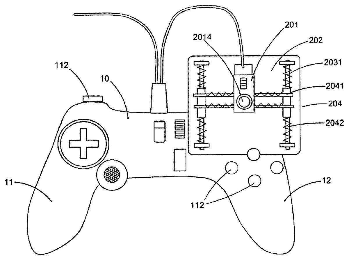
Referring toFIG. 1of the drawing, a game controller of the present invention comprises a controller housing10, a locating device20and a management module30. The controller housing10comprises a plurality of functional buttons are spacedly provided on the surface of the controller housing10for controlling a game character of a game. The management module30is received in the controller housing10for processing data generated by the function buttons and communicating with a game platform linked to the game controller. The locating device20is linked to the management module30for providing accurately locating the game character of the game.
The controller housing10of the game controller further comprises a left handle11and a right handle12. The left handle11is located on the left side of the controller housing10. The right handle12is located on the right side of the controller housing10. The left handle11and the right handle12are connected at the middle wire of the controller housing10. The functional buttons are divided into two parts, wherein one is the direction control buttons111provided on the surface of the left handle of the controller housing10, for controlling the moving direction of the game character, wherein another is the action buttons112separately provided on the surface of the right handle12of the controller housing10and on the back surface of the game controller for controlling action of the game character.
As shown inFIG. 5, the management module30further comprises a processing module302and a communication module303linked with each other.
Referring toFIG. 1of the drawing, the locating device20further comprises a displacement sensor201and a locating area202, wherein the locating area202is defined on the surface of the right handle12of the controller housing10. At one end of the displacement sensor201, a securing device2020is provided for securing the displacement sensor201on a finger wherein the displacement sensor201moves as the finger moves in the locating area202, so as to implement to control the game character action. In addition, the displacement sensor201links to the processing module302, so that when the displacement sensor201begins to move, the displacement sensor201sends a displacement data to the processing module302of the management module30. The displacement data includes the moving direction and moving distance of the displacement sensor201.
After the management module30of the management module30receives the displacement data that is sent by the displacement sensor201, the management module30processes and encapsulates the displacement data and generates formatted displacement data which is identified by the game platform. Then, the formatted displacement data of the displacement sensor201is sent to the communication module303. The communication module303sends the formatted displacement data of the displacement sensor201to the game platform. Through the game platform, the current place of the displacement sensor201would be shown on the display device linked to the game platform.
During the moving of the displacement sensor201, the displacement sensor201continually sends the displacement data of the displacement sensor201to the management module30and the management module30continually processes the displacement data of the displacement sensor201and generates the formatted displacement data. The management module30sends the formatted displacement data to the game platform, wherein the current place of the displacement sensor is showed on the display device through the game platform. Therefore, the moving path of the displacement sensor201can be shown on the display device rapidly and precisely.
When the displacement sensor201stops moving, the displacement sensor201stops sending the displacement data of the displacement sensor201to the management module30. The management module30stops sending the formatted displacement data of the displacement sensor201to the game platform, and then the display device shows the position when the displacement sensor201stops moving.
When the displacement sensor201is in a still condition, the displacement sensor201does not send the displacement data of the displacement sensor201to the management module30. The position of the displacement sensor201would not change during the still condition of the displacement sensor201. When the game character moves, the direction control buttons111send direction data to the management module30. The management module30processes the direction data, encapsulates the direction data, and generates the formatted direction data, so that the game platform can identify the formatted direction data, and then the formatted direction data are sent to the communication module303. The communication module303sends the formatted direction data to the game platform. The action data is sent by the action control buttons, and that the management module30also processes the action data, generates the formatted action data, and sends to the game platform. So that the game controller can accurately control the game character.
The holding device2020further comprises two resilient rings, wherein the finger is place between the two resilient rings and held between the two resilient rings for fixing the displacement sensor201. The holding device2020could be an elastic circle too, letting the finger passing through the elastic circle for holding the displacement sensor201in position.
A magnetic device is added on the locating area202and, at the same time, an iron plate is fixed on the displacement sensor201, so as to prevent the displacement sensor201dropping from the locating area202. Using the iron made locating area202and the magnetic device fixed on the displacement sensor201can achieve the same result.
According to a First Personal Shooting (FPS) game, the workable method of the locating device20is illustrated. In the FPS game, the locating device20controls a weapon cursor of a game character, so that the weapon can rapidly and accurately locate the firing target. Therefore, at the beginning of the game, the weapon cursor of the game character shows in the middle of a display device which is controlled by the locating device20, and the display device and the game controller are separately linked to the same game platform. The weapon cursor in-game movement is accompanied by the displacement sensor201moving cursor. When the displacement sensor201starts to move on the locating area202, the displacement sensor201which is scanned in the locating area202sends the displacement data to the processing module302of the management module30. The processing module302processes the displacement data and generates the formatted displacement data, and then the formatted displacement data are sent to the communication module303.
After the communication module303receives the formatted displacement data, the formatted displacement data will be sent to the game platform. After the game platform processed, the display device which is linked to the game platform shows the position thereof after the cursor has been moved.
When the displacement sensor201keeps moving on the locating area202, the displacement sensor201keeps sending the displacement data of the displacement sensor201to the management module30. After the management module30processes and generates the formatted displacement data, the formatted displacement data of the displacement sensor201are sent to the display device that is linked to the game platform through the game platform linked to the game controller. Therefore, the display device can rapidly and accurately show the moving path of the weapon cursor of the game character used by the displacement sensor201controlled. When the displacement sensor201suddenly stops moving, the displacement sensor201stops sending the displacement data to the management module30and the management module30stops sending the formatted displacement data of the displacement sensor201to the game platform. The display device shows the weapon cursor position and the displacement sensor30stops moving the place. So that the displacement sensor can achieve rapidly and precisely controlling of the weapon cursor of the game character being used.
The displacement sensor201of the locating device20of the game controller, preferably, is a photoelectric sensor, as shown inFIG. 15. The photoelectric sensor comprises a casing2016, an optical sensor2018, an optical lens2019, and a light source2017. The optical sensor2018, the optical lens2019and the light source2017are received in the casing2016. The light source2017is affixed on the back or left side or right side of the optical sensor2018. The optical sensor2018is linked to the management module30. The bottom surface of the casing2016is a work surface, having an opening in the middle thereof, so that when the light produced by the light source2017irradiates on the locating area202, the optical sensor2018can receive reflected light reflected by the locating area202through the optical lens2019. When the casing2016is working, its work surface is in contact with the locating area202. The light source2019is preferably a LED or a laser source. The optical sensor2018obtains moving direction and distance thereof for analyzing the scanned surface image of the locating area. If the optical sensor2018is a laser optical sensor, some kinds of the laser optical sensor can form an image without the optical lens.
Referring toFIGS. 2 and 3of the drawings, an alternative mode of the preferred embodiment is illustrated, wherein the locating area202of the locating device20of the game controller locates at the end of the right handle12of the controller housing10of the game controller. One end of the locating area202of the locating device20is connected with the surface of the right handle12of the controller housing10while the other end is extended out of the controller housing10of the game controller, so that the displacement sensor201can rapidly and accurately locate on the locating area202. Preferably, the locating area202of the locating device20has a rectangular surface. When the displacement sensor201of the locating device is, preferably, a photoelectric sensor, the displacement sensor201should better receive the light generated by itself and reflect back to the displacement sensor201, so that the precision of the locating device20is improved.
Referring toFIG. 4of the drawing, another alternative mode of the preferred embodiment is illustrated, wherein the locating area202of the locating device20of the game controller is located on the right handle12of the controller housing10. In other words, that position is the right stick position of the traditional gamepad which has two sticks. The adjacent side of the locating area202connects with the right handle12of the controller housing10. The other adjacent side of the locating area202is extended out of the controller housing10. Preferably, the locating area202of the locating device20has a rectangular surface. When the displacement sensor201of the locating device is, preferably, a photoelectric sensor, the displacement sensor201could better receive the reflected light generated by itself, so that the accurateness of the locating device20is improved.
Referring toFIG. 6of the drawing, an alternative mode of the preferred embodiment is illustrated, wherein the locating device20of the game controller further comprises a displacement sensor201, a locating area202and a sliding frame204, wherein the sliding frame204is provided on the locating area202and the displacement sensor201is mounted on the sliding frame204. Preferably, the locating area202has a rectangular surface. The sliding frame204further comprises a first track2041, which has both ends bent toward the back of the locating area202to form a “U” shape structure for clamping two opposite edge of the locating area202, so that the sliding frame204can move along with the edge of the locating area202. The displacement sensor201is mounted on the sliding frame204and the displacement sensor201slides along with the sliding frame204.
Preferably, the displacement sensor201is a photoelectric sensor. When the displacement sensor201moves from a centre of the locating area202to a lower right corner, the displacement sensor201moves along with the sliding frame204toward the right side edge of the locating area202. At the same time, the sliding frame204moves toward a lower side of the locating area202along with the edge of the locating area202. When the displacement sensor201moves to the right edge of the locating area202and the sliding frame204moves to the lower right corner, the locating sensor201is already moved to the lower right corner of the locating area202. The displacement sensor201which is mounted on the sliding frame204can be moved freely on the locating area202and be rapidly and accurately located at any position in the locating area202. The moving path of the displacement sensor201in the locating area202would be sent to the game platform by the management module30, which is then shown on the display device linked to the game platform. The sliding frame204provided on the locating area202enables an orientation of the displacement sensor201being not changed, that affects the accurateness of the locating. Preferably, the displacement sensor is a photoelectric sensor.
Referring toFIGS. 7 and 8of the drawings, an alternative mode of the preferred embodiment of the present invention is illustrated, wherein the locating device20of the game controller further comprises a displacement sensor201, a locating area202and a sliding frame204, wherein the sliding frame204is mounted on the locating area202and the displacement sensor201is mounted on the sliding frame204. Preferably, the locating area has a rectangular surface and two sliding slots2021are provided on two opposite side edges of the locating area202respectively. The two sliding slots2021are parallel and have a length the same as the length of the side of the locating area202.
The sliding frame204further comprises a first guider track2041and a movement device is provided at the both ends thereof. More preferably, the movement device comprises at least a wheel for mounting the two ends of the first guider track2041in the sliding slot2021of the opposite side edges of the locating area202, so that the first guider track2041can move from one side to another side along the locating area202.
The displacement sensor201is provided on the first guider track2041in order to move along the first guider track2041. Preferably, the displacement sensor201is a photoelectric sensor. When the displacement sensor201moves from a centre of the locating area202to a lower right corner of the locating area202, the displacement sensor201moves to a right edge of the locating area202along the sliding frame204, and, at the same time, the sliding frame204moves to a lower edge of the locating area202along the two sliding slots2021of the locating area202. When the displacement sensor201is located at the right edge of the locating area202and the sliding frame204is located the lower edge of the locating area202, the displacement sensor201is already located at the lower right corner of the locating area202. The displacement sensor201is mounted on the sliding frame204in such a manner that the displacement is able to move freely in the locating area202and locate rapidly and accurately at any position of the locating area202.
The moving path of the displacement sensor201in the locating area202is sent to the game platform through the management module30and shown on the display device linked to the game platform. Due to the sliding frame204provided on the locating area202, the orientation of the displacement sensor201would not change so as to affect the locating accurateness. The orientation of the displacement sensor201is the positive direction of the Y axis of a Cartesian coordinate system in where the displacement sensor201located. In other words, when the orientation of the displacement sensor201is same as the positive direction of the Y axis of the Cartesian coordinate system of the display device and the displacement sensor201moves along the positive direction of the Y axis of the Cartesian coordinate system, the weapon cursor of the game character controlled by the displacement sensor201also moves along the positive direction of the Y axis as shown on the display device. If the orientation of the displacement sensor201is the negative direction of the Y axis of the Cartesian coordinate system of the display device and the displacement sensor201moves along the positive direction of the Y axis of the Cartesian coordinate system, the weapon cursor of the game character controlled by the displacement sensor201will move along the negative direction of the Y axis as shown on the display device.
Referring toFIG. 9of the drawing, another alternative mode of the preferred embodiment of the present invention, wherein the locating device20of the game controller further comprises a displacement sensor201, a locating area202and a sliding frame204, wherein the sliding frame204is mounted on the locating area202and the displacement sensor201is mounted on the sliding frame. Preferably, the locating area202has a rectangular surface. The sliding frame204further comprises a first guider track2041and a second guider track2042, wherein the second guider track2042is located at a side edge of the locating area202. One end of the first guider track2041connects with the second guider track2042, and the other end of the first guider track2041is placed on the surface of the locating area202. The first guider track2041and the second guider track are perpendicular with each other. In addition, the second guider track2042has a linear bearing so that the first guider track2041can move along the second guider track2042. The displacement sensor201is affixed on the first guider track2041of the sliding frame204and can move along the first guider track2041. Preferably, the displacement sensor201is a photoelectric sensor. Since the displacement sensor201is affixed on the sliding frame204, it can move freely in the locating area202and rapidly and accurately move to any position of the locating area202. The moving path of the displacement sensor201on the locating area202is sent to the game platform through the management module30, and shown on the display device. The locating area202provided on the sliding frame204substantially renders the orientation of the displacement sensor201to remain no change, to affect he locating accurateness.
Referring toFIG. 10of the drawing, an alternative mode of the preferred embodiment of the present invention, wherein the locating device20of the game controller further comprises a displacement sensor201, a locating area202and a sliding frame204, wherein the sliding frame204is mounted on the locating area202and the displacement sensor201is mounted on the sliding frame204. Preferably, the locating area202has a rectangular surface. The sliding frame204further comprises a first guider track2041and two parallel second guider tracks2042, wherein two second guider tracks2042are mounted on two side edges of the locating area202. Two ends of the first guider track2041are connected with two second guider tracks2042respectively to form a “H” shape structure, so that the first guider track2041can be moved along the two parallel second tracks2042. The displacement sensor201is mounted on the first track2041, so that the displacement sensor201can be moved along the first guider track2041.
Preferably, the displacement sensor201is a photoelectric sensor. When the displacement sensor201moves to an upper-left corner of the locating area202, the displacement sensor201moves to a left edge of the locating area202along the first guider track2041, and, at the same time, the first guider track2041moves to the upper edge of locating area202along the two parallel second tracks2042. When the displacement sensor201is located at the left edge of the locating area202along the first guider track2041, the first guider track2041is located at the upper edge of the locating area202. Then, the displacement sensor201is located at the upper-left corner of the locating area202.
The displacement sensor201mounted on the sliding frame204can be moved freely within the locating area202and rapidly and accurately located at any position within the locating area202. The moving path of the displacement sensor201within the locating area202is sent to the game platform through the management module30and shown on the display device. The sliding frame provided on the locating area202substantially renders, the orientation of the displacement sensor201to remain no change so as to affect the locating accurateness.
Referring toFIG. 11of the drawings, another alternative mode of the preferred embodiment of the present invention, wherein the locating device20of the game controller is provided at one end of the right handle12of the controller housing10of the game controller112. The locating device20further comprises a displacement sensor202, a locating area202and a sliding frame204, wherein the sliding frame204is mounted on the locating area202and the displacement sensor201is mounted on the sliding frame204. The sliding frame204further comprises a first guider track2041and two parallel tracks2042, wherein two second guider tracks2042are located at two opposite side edges of the locating area202respectively and the two ends of the first guider track2041are connected with two second guider tracks2042respectively to form a “H” shape structure, so that the first guider track2041can be moved along the two second guider tracks2042. The locating area202is located between two second guider tracks2042.
The displacement sensor201further comprises a X axis displacement sensor2011and a Y axis displacement sensor2012. The X axis displacement sensor2011and the Y axis displacement sensor2012are respectively linked to the management module30, wherein the Y axis displacement sensor2011is mounted on an end of the first guider track2041that connects with the second guider track2042for scanning the displacement of the first guider track2041on the second guider track2042. The scanned result is sent to the management module30. The X axis displacement sensor2011is mounted on the first guider track2041enables it to be moved along the first guider track2041for scanning the displacement of the X axis displacement sensor2011on the first guider track2041, and then the scanned result is sent to the management module30. The X axis displacement sensor2011and the Y axis displacement sensor2012are respectively linked to the processing module302of the management module30.
When the displacement sensor201moves from a centre of the locating area202to an upper-left corner, the X axis displacement sensor2011is continuously sending the displacement data of the X axis displacement sensor2011to the processing module302of the management module30. The Y axis displacement sensor2012is continuously sending the displacement data of the Y axis displacement sensor2012to the processing module302of the management module30. When the processing module302receives the displacement data sent from the X axis displacement sensor2011and the Y axis displacement sensor2012respectively, the two displacement data are put into a group, and then that group of the two displacement data is detected to match for determining whether they are sent at the same time. If the displacement data of this group were not sent at the same time, abandon this group of displacement data, and then continue to detect the next group of displacement data. If the displacement data of such group were sent at the same time, the processing module302processes the group of displacement data and generates a formatted displacement data of the X axis displacement sensor2011and a formatted displacement data of Y axis displacement sensor2012, which are processed to generate a formatted displacement data of the displacement sensor201. After that the displacement data of the displacement sensor201are sent to the communication module303of the management module30. After the communication module303receives the formatted displacement data of the displacement sensor201sent by the processing module302, the formatted displacement data of the displacement sensor201is sent to the game platform, wherein after they are processed by the game platform, a moved position of the weapon cursor is shown on a display device linked to the game platform.
When the X axis displacement sensor2011is moved to a left side edge of the locating area202along the first guider track2041, at the same time, the first guider track2041is moved to an upper edge of the locating area202along two second guider tracks2042, and, therefore, the Y axis displacement sensor2012is also moved to the upper edge of the locating area202. During the moving of the X axis displacement sensor2011and Y axis displacement sensor2012, the X axis displacement sensor2011and Y axis displacement sensor2012continuously send the displacement data to the processing module302of the management module30respectively. The processing module302continuously processes the displacement data which are respectively sent from the X axis displacement sensor2011and the Y axis displacement sensor2012and generates the formatted displacement data of the X axis displacement sensor2011and the formatted displacement data of the Y axis displacement sensor2012. Then, the above formatted displacement data are continuously processed to finally generate the formatted displacement data of the displacement sensor201. Thereafter, the formatted displacement data of the displacement sensor201is sent to the communication module303. The communication module303continuously sends the formatted displacement data of the displacement sensor201to the game platform and then displayed on the display device linked to the game platform. The display device displays the moving path of the weapon cursor of the game character controlled by the displacement sensor201. The game player can rapidly and accurately control the weapon cursor of the game character used by the displacement sensor201.
When the X axis displacement sensor2011is moved to the left edge of the locating area202along the first guider track2041and the first guider track2041is moved to the upper edge of the locating area202, the X axis displacement sensor2011has been already moved to the upper-left corner of the locating area202. The displacement sensor201mounted on the sliding frame204is able to be moved freely within the locating area202and rapidly and accurately located any position within the locating area202. The sliding frame mounted on the locating area202would cause the orientation of the displacement sensor201to be remained no change, so as to affect the locating accurateness of the displacement sensor201. Preferably, the X axis displacement sensor2011and the Y axis displacement sensor are photoelectric sensors. Preferably, the photoelectric sensor is a granting sensor.
When the X axis displacement sensor2011is moved along the first guider track2041and the first guider track2041does not move along two second guider tracks2042, the X axis displacement sensor2011sends displacement data of the X axis displacement sensor2011to the processing module302of the management module30and the Y axis displacement sensor2012does not send displacement data of the Y axis displacement sensor2012. In this case, the processing module302of the management module does not process matched detecting but processes the displacement data of the X axis displacement sensor2011directly and generates formatted displacement data of the X axis displacement sensor2011. The processing module302doesn't receive the displacement data of the Y axis displacement sensor2012, so the formatted displacement data of the X axis displacement sensor2011is sent to the communication module303of the management module30. The communication module303sends the formatted displacement data of X axis displacement sensor2011to the game platform and displays on the display device linked to the game platform. On the display device, the weapon cursor of the game character being used is displayed moving along with the X axis.
When the first guider track2041moved along the two second guider tracks2042, the Y axis displacement sensor2012, following the first guider track2041, moves along the two second guider tracks2042. When the X axis displacement sensor2011does not move along the first guider track2041, the Y axis displacement sensor2012sends displacement data to the processing module302of the management module30and the X axis displacement sensor2011doesn't send displacement data of the X axis displacement sensor2011to the processing module302of the management module30. In this case, the processing module302of the management module30does not process matched detecting and processes the displacement data of the Y axis displacement sensor2012directly and generates formatted displacement data of the Y axis displacement sensor2012. The X axis displacement sensor2011does not send displacement data of the X axis displacement sensor2011to the processing module302of the management module30, so the formatted displacement data of Y axis displacement sensor2012is sent to the communication module303of the management module30. The communication module303sends the formatted displacement data of the Y axis displacement sensor2021to the game platform and displays on the display device linked to the game platform. The display device displays the weapon cursor of the game character moving along the Y axis.
When the displacement sensor201employs a scanning method as shown inFIG. 11for locating, the displacement sensor201further comprises a X axis displacement sensor2011and a Y axis displacement sensor2012, wherein the X axis displacement sensor2011and the Y axis displacement sensor2012are respectively linked to management module30and the X axis displacement sensor2011and the Y axis displacement sensor2012respectively scan the first guider track2041and the second guider track2042in order to confirm the displacement data of the X axis displacement sensor2011, so that it's not necessary to provide another plane as the locating area202, The locating area is provided between the two second guider tracks202, as shown inFIG. 12. In other words, if a sliding frame structure as shown inFIG. 12is employed, simply by utilizing the sliding frame204and the displacement sensor201, the weapon cursor of the game character can also locating a rapidly and accurately. In this structure, the locating device comprises the sliding frame204and the displacement sensor which is mounted on the sliding frame.
Referring toFIG. 13of the drawing, the locating device20of the game controller is provided on one end of the right handle112of the controller housing10of the game controller. The locating device20further comprises a displacement sensor201, a locating area202and a sliding frame204, wherein the sliding frame204is provided on the locating area202and the displacement sensor201is provided on the sliding frame204. The sliding frame further comprises a first guider track2041and a second guider track2042, wherein the second guider track2042is mounted on one side edge of the locating area202and one end of the first guider track2041is connected with the second guider track2042The first guider track2041and the second guider track2042are perpendicular with each other, so that the first guider track2041can be moved along the second guider track2042. The end where the first guider track2041is connected with the second guider track2042has a hole which has a size and a shape matched with the size and shape of a side of the second guider track2402, so that the second guider track2042can pass through the hole and the first guider track2041can be moved along the second guider track2042.
The displacement sensor201further comprises a X axis displacement sensor2011and a Y axis displacement sensor2012, wherein the X axis displacement sensor2011and the Y axis displacement sensor2012are respectively linked to the management module30, wherein the Y axis displacement sensor2012is provided at the end where the first guider track2041is connected with the second guider track2042for detecting the displacement of the first guider track2041which moves along the second guider track2042, and then the detected result is sent to the management module30. The X axis displacement sensor2011is mounted on the first guider track2041and arranged to be moved along the first guider track2401for detecting the displacement of the X axis displacement sensor2011on the first guider track2041, and then the detected result is sent to the management module30. The range of the locating area202means the freely movable range of the X axis displacement sensor2011on the sliding frame. Preferably, the X axis displacement sensor2011and the Y axis displacement sensor are photoelectric sensors. Preferably, the photoelectric sensor is a grating sensor.
Referring toFIG. 10of the drawing, another alternative mode of the preferred embodiment of the present invention is illustrated, wherein in order to enable the game player to rapidly and accurately find the displacement sensor201even while the game player has no need to leave his or her sight from the display device when the game player is playing a game, the locating device20further comprises a return device203, so that the displacement sensor201can be returned to its original position when the game player releases the finger pressed on the displacement sensor201. The original position of the displacement sensor201is a middle position of the first guider track2041, and, at the same time, the first guider track2041is provided on a middle of two second guider tracks2042.
The return device203further comprises a plurality of resilient elements2031respectively provided at both ends of the first guider track2041and both ends of two second guider tracks2042, wherein resilient element one end of the resilient element is connected with one end of the second guider track2042and the other end of the resilient element2031is connected with one end of the first guider track2041, so that the first guider track2041can return to the middle position of the two second guider tracks2042. Also, a plurality of resilient elements2031is respectively provided between the displacement sensor201and the first guider track2041resilient element respectively, wherein one end of the resilient element2031is connected with one end of the first guider track2041while the other end of the resilient element2031is connected with the displacement sensor201, so that the displacement sensor201can return to the middle position of the first guider track2041.
When the displacement sensor201is located in an initial position, the forces applied by the resilient elements2031against the displacement sensor201is in a balance condition, and, at the same time, the forces applied by the resilient elements2031against the first guider track2401is in a balance condition. resilient element resilient element When the displacement sensor201moves away from the initial position, the balance condition of the forces is broken, a retracted force is thus generated rendering the displacement sensor201returning to the initial position. Preferably, the resilient element2031can be a spring, tension spring or rubber band.
In order to enable the weapon cursor used by the game character does not move with the displacement sensor201on the display device during the returning of the displacement sensor201to the initial position (in other words, the displacement sensor201isn't in working condition during returning to the initial position), a switch2014is provided on the displacement sensor201, wherein the switch2014is connected with the displacement sensor201for controlling the working condition of the displacement sensor201. The switch2014can be a touch sensor that, when the finger of the game player touches the switch2014, the displacement sensor201is in the working condition and the displacement sensor201controls the weapon cursor of the game character being used. When the finger of the game player removes from the switch2014, the displacement sensor201stops working, and, at this time, the displacement sensor201stops controlling the weapon cursor used by the game character, so that the weapon cursor doesn't move with the displacement sensor201.
The switch2014can be a retracting element2015, having a resilient ability, provided on the displacement sensor201so as to retain the displacement sensor201an effective distance of the detection displacement thereof. When the game player slightly presses down the displacement sensor201to render the displacement sensor201to return to the effective distance of the detection displacement, the displacement sensor201is in the working condition. When the finger of the game player moves away from the displacement sensor201, the displacement sensor201moves away the effective distance of the detection displacement due to the resilient element, so that the displacement of the displacement sensor201becomes not detectable and thus the weapon cursor used by the game character will not move with the displacement sensor201.
Referring toFIG. 14of the drawings, the return device203further comprises a retracting wire axle2032, which is mounted on the bottom surface of the locating area202, and a central hole2022is provided in the middle of the locating area202. The retracting wire axle2032of the return device203has a wire winding there around, wherein one end of the wire penetrates through the central hole2022to connect with wire the displacement sensor201. When the displacement sensor201moves, the wire is pulled out from the retracting wire axle2032. When the game player releases his or her finger, the retracting wire axle2032starts to retract the wire and pulls the displacement sensor201back to the initial position, i.e. the centre of the location area202.
The return device203further comprises an affixing end2033located in the centre of the locating area202, a resilient element2031having one end connected with the affixing end2033and the other end connected with the displacement sensor201, wherein when the displacement sensor201is in the initial position, that is in the middle of the locating area202, the resilient element2031is in a balance condition. In other word, at this time, the resilient element2031is in natural extension. If the displacement sensor201moves away from the initial position, the resilient element2031would generate a retracting force to the displacement sensor201to drive the displacement sensor201to return to the initial position. The game player releases his or her finger, the displacement sensor201would return the initial position rapidly and accurately.
Referring toFIG. 18toFIG. 21of the drawings, a game controller according to a preferred embodiment of the present invention is illustrated, in which the game controller is for video gaming activity and is electrically connected to a video game platform, and comprises a controller housing10, a management module30received in the controller housing10, a control panel14, and a locating device20. The control panel14comprises a direction control button111and a plurality of action control buttons112spacedly provided on the controller housing10.
According to the preferred embodiment of the present invention, the controller housing10is ergonomically designed to be grabbed by a user's hand, and has a main portion13, and two side gripping portions, the left handle11and the right handle12, rearwardly extended from two sides of the main portion13.
The management module30is electrically connected to the control panel14and the locating device20, and is electrically connected to a game platform, such as a PLAYSTATION 3, for providing input commands for gaming activities. The electrical connection between the management module30can be wired or through wireless technology, such as Bluetooth technology. Thus, the game controller further comprises a connection socket50provided on the controller housing10for electrically connecting to the game platform via a predetermined cable51. The management module30comprises a predetermined Integrated Circuit for processing input commands which are to be transmitted to the game console.
The locating device20comprises a displacement sensor201provided on the controller housing10, and a securing device2020mounted on the displacement sensor201, wherein a user's thumb is arranged to detachably engage to the securing device2020for controllably initiating movement commands to the displacement sensor201. More specifically, the securing device2020comprises an elongated supporting member421extended from the displacement sensor201, and a plurality of resilient rings422spacedly provided on the elongated supporting member421, wherein the user's thumb is arranged to pass through the resilient rings422to physically communicate with the displacement sensor201. Thus, each of the resilient rings422has a predetermined diameter which is slightly larger than a diameter of the user's thumb so as to allow the user's thumb to easily pass through the resilient rings422.
As shown inFIG. 21of the drawings, the displace sensor201is mounted on a front end portion of the elongated supporting member421in such a manner that when the user's thumb is put in the resilient rings422, the user's thumb is allowed to drive the displace sensor201to move.
The locating device20further comprises a movement detection device43provided at a front corner portion of the controller housing10, wherein the displacement sensor201and the securing device2020are arranged to move on top of the movement detection204for initiating corresponding in-game cursor's movements. Note that the movement detection204can be mounted on the controller housing10through a variety of means, such as through magnets attached between the movement detection device43and the controller housing10.
As shown inFIG. 21of the drawings, the displacement sensor201comprises an outer casing2016, a sensor circuitry2013received in the outer casing2016, an optical sensor2018mounted on the sensor circuitry2013, an optical lens2019mounted on the optical sensor2018, and an illuminating device2017received in the outer casing2016and is positioned adjacent to the optical lens2019, wherein the illuminating device2017is arranged to generate a predetermined amount of illumination toward the movement detection device43. On the other hand, the displacement arrangement201further comprises a connection cable44electrically connecting the displacement sensor201and the management module30through the connection socket50provided on the controller housing10. It is worth mentioning that the displacement sensor201is in physical contact with the movement detection device43when it is used to control cursor's movement in a gaming screen.
The operation of the present invention is as follows: a user may grab the controller housing10with both hands, while placing his or her thumb into the resilient rings of the securing device2020. When the user is playing first personal shooting games, the user may move his or her thumb on top of the movement detection device43for controlling cursor's movement in the game. The movement of the user's thumb will drive the displacement sensor201to move as well. The corresponding movement of the displacement sensor201is processed by the sensor circuitry2013and transmitted to the management module30. The corresponding signal is then transmitted to the game platform for initialing the cursor movement.
The game controller further comprises a wireless transceiver60received in the controller housing10and is electrically connected to management module30for wirelessly transmitting control signals to the game platform.
Moreover, it is important to mention that the game controller of the present invention can be set to support video gaming console and computer gaming, so that the user is able to select which different modes of operations for playing games on video game consoles or computers. Thus, the connection socket50is embodied as a USB socket for connecting to a USB port of a computer, so as to allow the user of the present invention to control cursor movement when playing computer games.
Referring toFIG. 22toFIG. 25of the drawings, an alternative mode of the game controller according to the above embodiment of the present invention is illustrated. This alternative mode is similar to the above embodiment as shown inFIGS. 18-21, except that the game controller further comprises a vibration device70′ provided in the controller housing10, and is electrically connected to the management module30in such a manner that when game played by the gaming platform is programmed to generate vibration on the part of the game controller, the vibration device70′ is arranged to generate vibration of a predetermined magnitude and a predetermined duration.
Moreover, the illuminating device2017′ is embodied as a laser emitting device which is arranged to generate laser beam toward the movement detection device43′. Furthermore, each of the optical lens2019and the illuminating device2017′ is positioned in the outer casing2016at a predetermined angle of inclination toward each other for allowing effective reflection of laser beam at the movement detection device43′.
As shown inFIG. 22toFIG. 23of the drawings, the movement detection device43′ comprises a supporting base431′, a first guider track2041′ and two parallel guider track2042′ spacedly mounted on the supporting base431′, and a plurality of resilient elements2031′ mounted on the first guider track2041′ and two the second guider tracks2042′ respectively, wherein the displacement sensor201is movably mounted with respective to the first guider track2041′ and two the second guider tracks2042′, in such a manner that the displacement sensor201is capable of sliding along the first guider track2041′ and having a transverse displacement with respect to the controller housing10(but along a longitudinal direction of two second guider tracks2042′).
More specifically, the two the second guider tracks2042′ are transversely mounted on two side portions of the supporting base431′ of movement detection device43′ while the first guider track2041′ is extended between the two the second guider track2042′ so that the displacement sensor201is capable of moving in a plurality of directions for controlling the movement of cursors on a gaming screen.
Furthermore, the movement detection device43′ further comprises a plurality of sliding members434′ slidably mounting the two the second guider track2042′ with two ends of the first guider track2041′ so as to allow a transverse movement (with respect to the controller housing10but along a longitudinal direction of the two second guider track2042′) of the first guider track2041′. In this alternative mode, the displacement sensor201is mounted on the first guider track2041′ so that the displacement sensor201is capable of moving along the transverse direction of the first guider track2041′, as well as the longitudinal direction of two the second guider track2042′ for controlling cursor's movement in the corresponding direction.
On the other hand, the resilient elements2031′ are arranged to bias against the displacement sensor201and the sliding members434′ for driving them to move back to their respective original position when the user has moved it to another position. In this alternative mode, the displacement sensor201is mounted at a mid portion of the first guider track2041′ as an original position thereof. As such, the user is able to slide the displacement sensor201along the first guider track2041′ for controlling a horizontal movement of the cursor, while the user is also able to slide the displacement sensor201along the two the second guider tracks2042′ for controlling a vertical movement of the cursor. After movement of the cursor, the resilient elements2031′ will move the displacement sensor201and the sliding members434′ back to their original positions respectively. The displacement sensor201further comprises a plurality of switches2014formed on the outer casing2016for selectively operating the displacement sensor201and for adjusting sensor's sensitivity.
When the displacement sensor201is in use, the user may put his or her thumb onto the switch2014so as to turn on the displacement sensor201. The user may then move the displacement sensor201to a desirable position so as to control the cursor's movement. After the cursor's movement has completed, the user may relieve the pressing force exerted to the switch2014and turn off the displacement sensor201. Furthermore, the displacement sensor201will then be driven back to its original position by the resilient element2031′. Moreover, the switch2014may be made of material having high coefficient of friction for enabling the user to easily move the displacement sensor201.
As a slight alternative, the first guider track2041′ and two the guider track2042′ can be configured in a manner as shown inFIG. 26toFIG. 27of the drawings. Each of the first guider track2041′ and the two second tracks2042′ has an elongated slot4324′ formed therein, wherein the sliding members434′ are mounted in the elongated slots4324′ of the two guider tracks2041′ respectively. Thus, the first guider track2041′ is allowed to slidably move with respect to two the second guider tracks2042′.
Referring toFIG. 28toFIG. 30of the drawings, another alternative mode of the game controller according to the above embodiment of the present invention is illustrated. The alternative mode is similar to the above alternative mode as shown inFIGS. 22 to 25, except that the locating device20further comprises an addition displacement sensor45′ provided at one end of the first guider track2041′ for controlling a transverse movement of the cursor by detecting a transverse movement of the first guider track2041′. The displacement sensor201is still provided at a mid portion of the first guider track2041′ for controlling a longitudinal movement of the cursor in a manner as mentioned above.
Referring toFIG. 31toFIG. 34of the drawings, another alternative mode of the game controller according to the above embodiment of the present invention is illustrated. The alternative mode is similar to the above alternative mode as shown inFIGS. 22 to 25, except that the displacement sensor201A. According to this alternative mode, the displacement sensor201A is embodied as a diffractive sensor which is arranged to determine sensor's movement by diffraction. More specifically, the displacement sensor201A comprises an outer casing2016A having a diffraction slot4111A, a sensor circuitry2013A received in the outer casing2016, an optical sensor2018A electrically connected with the sensor circuitry2013A, an optical lens2019A provided in the outer casing2016A at a position opposite to the sensor circuitry, an illuminating device2017A provided in the outer casing2016A and is arranged to generate illumination toward the optical lens2019A, and a diffraction slit member416A supported in the diffraction slot4111A, wherein the light generated by the illuminating device2017A is arranged to pass through the optical lens2019A from one side of the diffraction slot4111A and diffracted by the diffraction slit member416A and reach the optical sensor2018A positioned opposite to the optical lens2019A (i.e. the other side of the diffraction slot4111A).
In this alternative mode, the locating device20A further comprises an addition displacement sensor45A provided at one end of the first guider track2041′ for controlling a transverse movement of the cursor by detecting a transverse movement of the first guider track2041′. The displacement sensor201A is still provided at a mid portion of the first guider track2041′ for controlling a longitudinal movement of the cursor in a manner as mentioned above. Note that both the displacement sensor201A and the addition displacement sensor45A are diffractive sensors having the structure as mentioned above.
As shown inFIG. 31of the drawings, it is worth mentioning that the diffraction slit member416A of each of the displacement sensor201A and the addition displacement sensor45A is supported along the first guider track2041′ and the second guider track2042′ respectively for accomplishing diffraction of light beams generated by the corresponding illuminating device415A.
Referring toFIG. 35of the drawings, another alternative mode of the game controller according to the above embodiment of the present invention is illustrated. This alternative mode is similar to the above alternative mode as shown inFIGS. 22 to 25, except that the controller housing10B. In this alternative mode, the controller housing10B comprises a first housing body13B and a second housing body14B, wherein the first and the second housing body13B,14B are electrically connected through a wire15B.
In this alternative mode, the management module30and the action control buttons112are received in the second housing body14B while the direction control device111of the control panel30is provided on the first housing body13B. The locating device20is provided on the second housing body14B so that the user may use one of his or her hands for controlling cursor movement and operate the action control buttons112, wherein his or her remaining hand is used for controlling the direction control device111. The direction control signals are then transmitted to the management module30through the wire15B or in a wireless manner.
Referring toFIG. 36toFIG. 37of the drawings, another alternative mode of the game controller according to the above embodiment of the present invention is illustrated. This alternative mode is similar to the above alternative mode as shown inFIGS. 22 to 25, except that the movement detection device43C. In this alternative mode, the movement detection device43C comprises supporting base431C and first and second guider track2041C,2042C, mounted on the supporting base431C, wherein the displacement sensors201C,45C are mounted on the first and the second guider tracks2041C,2042C respectively. InFIG. 36of the drawings, there is only one guider track, i.e. the first guider track2041C mounted on the supporting base431C.
Referring toFIG. 38toFIG. 39of the drawings, another alternative mode of the game controller according to the above embodiment of the present invention is illustrated. This alternative mode is similar to the above alternative mode as shown inFIGS. 22 to 25, except that the movement detection device43C. In this alternative mode, the movement detection device43C comprises first supporting a base2141C and two second supporting base2142C mounted underneath the first guider track2041C and the two second guider tracks2042C respectively, wherein the displacement sensors2011C,2012C are mounted on the first and the second guider tracks2041C,2042C respectively.
It is important to mention that the movement detection device. In the event that there are only first and the second guider track2041C,2042C, the movement detection device43C comprises merely first and the second supporting base2141C,2142C for mounting underneath the first and the second guider track2041C,2042C respectively.
The displacement sensor201of the locating device20has two connecting method, the first method is above recited that the displacement sensor201links to the game platform through the management module30of the game controller, the second method is that added a management module30on the displacement sensor201, the management module30of the displacement sensor201separately links to the displacement sensor201and the game platform, so the displacement sensor201links to the game platform directly without through the management module30of the game controller. As shown onFIGS. 16 and 17. Compare with two connecting method, the second method just added a management module30which links to the displacement sensor201so that the displacement sensor201can link to the game platform directly and didn't need to link to the game controller, the other technical characteristic of the second method as the same as the first method that included the processing data method of the management module30which the management module30links to the displacement sensor201and the data is sent by the displacement sensor30.
According to the game supported the different game controller, the game is divided into two types, one just supported keyboard and mouse, the other supported the gamepad. But the game controller of the present invention is supported by the game of above type. It worth mentioning that in order to support above two type of game, the game controller employs three work mode A, B and C, wherein mode A is mouse mode, which also is the default mode of the game controller of the present invention, mode B is analogue joystick mode, mode C is analogue mouse mode. Pressing a function key of the game controller to change above three work mode. If the game only supported keyboard and mouse, the game controller of the present invention works on mode A, if the game only supported gamepad, the game controller of the present invention works on mode B or mode C.
The following utilizes a FPS game as example to illustrate the work process of the game controller of the present invention under above three work mode. In the FPS game, the weapon cursor of the game character used is controlled by the displacement sensor201. The displacement sensor201, preferable is a photoelectric sensor.
When the game controller of the present invention works on mode A, the data format which the FPS game can identify as the same as the default encapsulation format of the management module30of the game controller of the present invention, so it isn't necessary to process the data, the data can send to the game platform directly. The detail work process as recited above.
When the FPS game only supported gamepad, the game controller of the present invention works on mode B or mode C, at this time, the data need to change format which is sent to the game platform by the management module30, so that the displacement sensor201of the locating device20of the game controller of the present invention should control the weapon cursor of the game character used of the FPS game. In fact, the processing module302of the management module30changes the data format which is sent to the game platform.
The detail process of the data change by the processing module302of the management module30describes as the following.
The specific definition of the joystick signal of the ordinary gamepad is that: the coordinate axis x and coordinate axis y represent the location of the stick, according to the location of the joystick, the coordinate axis x and coordinate axis y of the stick through analog to digital converted, the digital signal between 0 and 255 is sent to the game platform. According the digital signal to determine the moving direction and speed of the cursor. When the axis x send the data to the game platform between 129 and 255, the cursor of the game moves toward right, the data more bigger the moving more faster, at the 255 the moving speed achieves top speed.
When the game controller of the present invention work on the mode B or mode C, the displacement data of the displacement sensor201is changed into the displacement value by the processing module302of the management module30, the displacement value is integer that between 0 and 255. The specific process is that:
The processing module302of the management module30counts the displacement data of the displacement sensor201, generated the actual moving value. The processing rule is every eight moving unit records1, the maximum does not exceed 255.
After that, according to the setting sensitivity of the displacement sensor201, processing the actual moving value of the displacement sensor201, generated the displacement value of the displacement sensor201. The rules of processing the procedure is that: the displacement value of the displacement sensor201=the actual moving value of the displacement value of the displacement sensor201×the setting sensitivity of the displacement value. The maximum displacement value does not exceed 255. The setting sensitivity is between 1 and 8.
When the work mode of the game controller is mode B, the displacement sensor201simulates the control method of the right stick which controls the weapon cursor of the game character using. When the displacement sensor201locates in the centre of the locating area202, the weapon cursor of the game character using does not move, when the displacement sensor201moving, the weapon cursor start to move. In the FPS game, the more the displacement sensor201is far away from the centre of the locating area202, the more the weapon cursor moves faster.
In work mode B, the steps that the displacement sensor201simulates the right stick by the management module30as following:
Step one, the management module30detects whether the displacement sensor201is in work state, if the displacement sensor201isn't in work state, then the communication module303of the management module30would simulate the coordinate of the current position of the displacement sensor201, the axis x value of the right stick=128, the axis y value of the right stick=128, then sent the coordinate value to the game platform; if the displacement sensor201is working, the go to next step.
Step two, if the displacement sensor201moves towards the positive direction of axis X, then the axis X value of the present position of the displacement sensor201would be simulated the axis X value of the right stick, the axis X value of the right stick=the axis X value of the right stick+axis X moving value of the sensor, if the axis X value of the right stick more than 255, then the axis X value of the right stick=255, and go to next step; if the displacement sensor201moves towards the negative direction of axis X, then the axis X value of the right stick=the axis X value of the right stick−the axis X moving value of the sensor, if the difference value less than 0, then the axis X value of the right stick=0, and go to next step.
Step three, if the displacement sensor201moves towards the axis Y positive direction, then the axis Y value of the displacement sensor201present position would be simulated the axis Y value of the right stick by the communication, the axis Y value of the right stick=the axis Y value of the right stick+the axis Y moving value of the sensor, if the summation more than 255, then the axis Y value of the right stick=255, and go to next step; if the displacement sensor201moves towards the axis Y negative direction, then the axis Y value of the displacement sensor201would be simulated the axis Y value of the right stick by the communication module303, the axis Y value of the right stick=the axis Y value of the right stick−the moving value of the sensor, if the difference value less than 0, then the axis Y value of the right stick=0, and go to next step.
Step four, the axis X value of the right stick and the axis Y value of the right stick are sent to the game platform, which generated by the displacement sensor is simulated the right stick, then this process is done.
When the game controller of the present invention's work mode is mode C, the communication module303of the management module30changes the displacement data of the displacement sensor201into the data format of the right stick, as the following step:
Step one, the displacement sensor201sends the displacement data to the processing module302of the management module30, the processing module302judges whether the displacement sensor201is moving, if the displacement isn't moving, then the processing module302simulates the present position of the displacement sensor201to the coordinate value of the right stick that the axis X value of the right stick=128, the axis Y value of the right stick=128, if the displacement is moving, the go to next step.
Step two, when the displacement sensor201moves toward axis X positive direction, the processing module302is simulating the coordinate of the displacement sensor201, the axis X value of the right stick=128+the axis X displacement value of the displacement sensor, if the axis X value of the right stick more than 255, then the axis X value of the right stick is 255, and go to next step; if the displacement sensor201moves towards axis X negative direction, the processing module302is simulating the coordinate of the displacement sensor201, the axis X value of the right stick=128−the axis x displacement value of the displacement sensor, if the axis X value of the right stick less than 0, then the axis X value of the right stick=0, and go to next step.
Step three, when the displacement sensor201moves toward axis Y positive direction, the processing module302is simulating the coordinate of the displacement sensor201, the axis Y value of the right stick=128+the axis Y displacement value of the displacement sensor, if the axis Y value of the right stick more than 255, then the axis Y value of the right stick is 255, and go to next step; if the displacement sensor201moves towards axis Y negative direction, the processing module302is simulating the coordinate of the displacement sensor201, the axis Y value of the right stick=128−the axis x displacement value of the displacement sensor, if the axis Y value of the right stick less than 0, then the axis Y value of the right stick=0, and go to next step.
Step four, the axis X value of the right stick and the axis Y value of the right stick are sent to the game platform, which generated by the displacement sensor is simulated the right stick, then this process is done.
When the game controller of the present invention utilizes a FPS game which supported the mouse, the game controller of the present invention as the same aiming performance as the mouse, the aiming speed and accurateness is better than ordinary stick. When the game controller of the present invention utilizes a FPS game which supported stick, the work mode of the game controller is mode C, compare with ordinary stick has two advantage. One is the cursor has rapidly reflect speed. Ordinary stick used analog potentiometer, comprises a base and a control stick, controlling the moving speed of the cursor in the game by the control stick the degree of inclination, the stick is unstable. To control the instability of the stick, usually setting a middle death zone which locates in the middle of the base, the cursor of the game does not move when the control stick in middle death zone. (It is not necessary to need a left stick in the game controller, the game controller could only have right stick to control the cursor.) Only the control stick out of the death zone, the cursor start to move, in this way the aiming time is delay. But the displacement sensor has not the middle death zone, when moving the displacement sensor201, the cursor also moving immediately. The other is the cursor can change direction immediately during the cursor moving rapidly. When the cursor is moving rapidly, the control stick locates the father away from the base centre, at this time, if the cursor need to move to opposite direction, the control stick need to move a long distance, and the control stick still need to pass the middle death zone, but utilizing the game controller of the present invention, no matter how the cursor current speed, pushes the displacement sensor less than 0.1 mm towards the direction which you wants the cursor moving, the cursor will move follow the direction.
The management system of the game controller of the present invention, comprises:
A processing module302and a communication module303which links with each other, wherein the processing module302process a displacement data, produces a formatted displacement data, so that a game platform can identify the formatted displacement data which links with the processing module302, the formatted displacement data is sent to the communication module303; the communication module303sends the formatted displacement data to the game platform which is processed by the processing module302.
One skilled in the art will understand that the embodiment of the present invention as shown in the drawings and described above is exemplary only and not intended to be limiting.
It will thus be seen that the objects of the present invention have been fully and effectively accomplished. It embodiments have been shown and described for the purposes of illustrating the functional and structural principles of the present invention and is subject to change without departure from such principles. Therefore, this invention includes all modifications encompassed within the spirit and scope of the following claims.
Claims
- A game controller for a game, comprising: a controller housing, wherein a plurality of function buttons is provided on said controller housing for operating a game character of said game;a management module received in said controller configured to process data which is generated by said function buttons and processing Communication with a game platform of said game linked to said game controller;a locating device linked to said management module configured to accurately locate said game character in said game, wherein said locating device defines a locating area and comprises a sliding frame mounted on said locating area, and a displacement sensor moving within said locating area and while an orientation of said displacement sensor is remained unchanged, wherein said sliding frame comprises a first guider track and two parallel second guider tracks, wherein said two guider second tracks are mounted on two opposite side edges of said locating area, wherein two ends of said first guider track are slidably connected with said two second guider tracks to form a “H” shape structure, so that said first guider track is able to move along said two second guider tracks, wherein said displacement sensor is slid along said first guider track such that said displacement sensor is freely moved within said locating area via a sliding movement between said displacement sensor and said first guider track and a sliding movement between said first and second guider tracks, and wherein said locating device further comprises a touch sensor switch mounted on said displacement sensor configured to control a working condition of said displacement sensor, such that said displacement sensor is activated when there is a touch of said touch sensor switch.
- The game controller, as recited in claim 1 , wherein said displacement sensor is a photoelectric sensor.
- The game controller, as recited in claim 2 , wherein said locating device further comprises a return device for ensuring said displacement sensor to be returned back to a middle initial position of said locating area, wherein said return device comprises a plurality of first resilient elements provided at said first guider track for applying forces to said displacement sensor to slide at a middle of said first guider track, and a plurality of second resilient elements provided at said second guider tracks respectively for applying forces to said first guider track to slide at a middle of each of said second guider tracks.
- The game controller, as recited in claim 3 , wherein said first resilient elements are provided at two ends of said first guider track respectively at a position that said displacement sensor is located between said first resilient elements such that said displacement sensor is pushed by said first resilient elements to slide at the middle of said first guider track, wherein said second resilient elements are provided at two ends of each of said second guider tracks respectively at a position that said first guider track is located between said second resilient elements, such that said first guider track is pushed by said second resilient elements to slide at the middle of each of said second guider tracks.
- The game controller, as recited in claim 4 , wherein said locating area is located at a right handle of said controller housing at a position that one end of said locating area is connected with a top surface of said right handle of said controller housing and another end of said locating area is extended out of said controller housing.
- The game controller, as recited in claim 5 , wherein said management module further comprises a processing module and a communication module interlinked with each other, wherein when said displacement sensor is moved, said processing module simulates a coordinate of said displacement sensor and collects displacement data therefrom to generate formatted displacement data, wherein said communication module receives said formatted displacement data and sends said formatted displacement data to said game platform.
- The game controller, as recited in claim 2 , wherein said first resilient elements are provided at two ends of said first guider track respectively at a position that said displacement sensor is located between said first resilient elements such that said displacement sensor is pushed by said first resilient elements to slide at the middle of said first guider track, wherein said second resilient elements are provided at two ends of each of said second guider tracks respectively at a position that said first guider track is located between said second resilient elements, such that said first guider track is pushed by said second resilient elements to slide at the middle of each of said second guider tracks.
- The game controller, as recited in claim 2 , wherein said locating area is located at a right handle of said controller housing at a position that one end of said locating area is connected with a top surface of said right handle of said controller housing and another end of said locating area is extended out of said controller housing.
- The game controller, as recited in claim 1 , wherein said locating device further comprises a return device for ensuring said displacement sensor to be returned back to a middle initial position of said locating area, wherein said return device comprises a plurality of first resilient elements provided at said first guider track for applying forces to said displacement sensor to slide at a middle of said first guider track, and a plurality of second resilient elements provided at said second guider tracks respectively for applying forces to said first guider track to slide at a middle of each of said second guider tracks.
- The game controller, as recited in claim 1 , wherein said locating area is located at a right handle of said controller housing at a position that one end of said locating area is connected with a top surface of said right handle of said controller housing and another end of said locating area is extended out of said controller housing.
- The game controller, as recited in claim 1 , wherein said management module further comprises a processing module and a communication module interlinked with each other, wherein when said displacement sensor is moved, said processing module simulates a coordinate of said displacement sensor and collects displacement data therefrom to generate formatted displacement data, wherein said communication module receives said formatted displacement data and sends said formatted displacement data to said game platform.
- A locating device for a game controller having a controller housing to control a game, comprising: a management module, the management module being received in said controller housing, and processing communication with a game platform of said game linked to said game controller;a locating area defined on said controller housing;a displacement sensor linked to said management module and being moved within said locating area for accurately locating a game character in said game, wherein an orientation of said displacement sensor is remained unchanged when said displacement sensor is moved within said locating area, and wherein a touch sensor switch is mounted on said displacement sensor configured to control a working condition of said displacement sensor, such that said displacement sensor is activated when there is a touch of said touch sensor switch;and a sliding frame, the sliding frame mounted on said locating area, comprising a first guider track and two parallel second guider tracks, wherein said two guider second tracks are mounted on two opposite side edges of said locating area, wherein two ends of said first guider track are slidably connected with said two second guider tracks to form a “H” shape structure, so that said first guider track is able to move along said two second guider tracks, and wherein said displacement sensor is slid along said first guider track such that said displacement sensor is freely moved within said locating area via a sliding movement between said displacement sensor and said first guider track and a sliding movement between said first and second guider tracks.
- The locating device, as recited in claim 12 , wherein said displacement sensor is a photoelectric sensor.
- The locating device, as recited in claim 13 , wherein said locating device further comprises a return device for ensuring said displacement sensor to be returned back to a middle initial position of said locating area, wherein said return device comprises a plurality of first resilient elements provided at said first guider track for applying forces to said displacement sensor to slide at a middle of said first guider track, and a plurality of second resilient elements provided at said second guider tracks respectively for applying forces to said first guider track to slide at a middle of each of said second guider tracks.
- The locating device, as recited in claim 14 , wherein said first resilient elements are provided at two ends of said first guider track respectively at a position that said displacement sensor is located between said first resilient elements such that said displacement sensor is pushed by said first resilient elements to slide at the middle of said first guider track, wherein said second resilient elements are provided at two ends of each of said second guider tracks respectively at a position that said first guider track is located between said second resilient elements, such that said first guider track is pushed by said second resilient elements to slide at the middle of each of said second guider tracks.
- The locating device, as recited in claim 15 , wherein said locating area is located at a right handle of said controller housing at a position that one end of said locating area is connected with a top surface of said right handle of said controller housing and another end of said locating area is extended out of said controller housing.
- The locating device, as recited in claim 16 , wherein said management module further comprises a processing module and a communication module interlinked with each other, wherein when said displacement sensor is moved, said processing module simulates a coordinate of said displacement sensor and collects displacement data therefrom to generate formatted displacement data, wherein said communication module receives said formatted displacement data and sends said formatted displacement data to said game platform.
- The locating device, as recited in claim 13 , wherein said first resilient elements are provided at two ends of said first guider track respectively at a position that said displacement sensor is located between said first resilient elements such that said displacement sensor is pushed by said first resilient elements to slide at the middle of said first guider track, wherein said second resilient elements are provided at two ends of each of said second guider tracks respectively at a position that said first guider track is located between said second resilient elements, such that said first guider track is pushed by said second resilient elements to slide at the middle of each of said second guider tracks.
- The locating device, as recited in claim 13 , wherein said locating area is located at a right handle of said controller housing at a position that one end of said locating area is connected with a top surface of said right handle of said controller housing and another end of said locating area is extended out of said controller housing.
- The locating device, as recited in claim 12 , wherein said locating device further comprises a return device for ensuring said displacement sensor to be returned back to a middle initial position of said locating area, wherein said return device comprises a plurality of first resilient elements provided at said first guider track for applying forces to said displacement sensor to slide at a middle of said first guider track, and a plurality of second resilient elements provided at said second guider tracks respectively for applying forces to said first guider track to slide at a middle of each of said second guider tracks.
- The locating device, as recited in claim 12 wherein said locating area is located at a right handle of said controller housing at a position that one end of said locating area is connected with a top surface of said right handle of said controller housing and another end of said locating area is extended out of said controller housing.
- The locating device, as recited in claim 12 , wherein said management module further comprises a processing module and a communication module interlinked with each other, wherein when said displacement sensor is moved, said processing module simulates a coordinate of said displacement sensor and collects displacement data therefrom to generate formatted displacement data, wherein said communication module receives said formatted displacement data and sends said formatted displacement data to said game platform.
Disclaimer: Data collected from the USPTO and may be malformed, incomplete, and/or otherwise inaccurate.