U.S. Pat. No. 8,696,460
GAME CONTROLLER WITH AT LEAST ONE INTERMEDIARY LOCKING POSITION
AssigneeGuillemot Corporation S.A.
Issue DateFebruary 25, 2011
Illustrative Figure
Abstract
A game controller having at least one arm mobile in relation to a base over a nominal range of displacement between two extreme positions, which implements a stopping mechanism of the aim 1n an intermediary locking position between the extreme positions to avoid reaching involuntarily a zone of the nominal range of displacement. An element of the stopping mechanism is removable and/or retractable with respect to the base so that this element is able to take two positions, an active position, wherein the stopping mechanism in the intermediary locking position is active and cooperates with the base and the arm, and an inactive position, wherein the stopping mechanism is inactive. The game controller also implements mechanical means of crossing the intermediary locking position under the action of a specific control carried out by a user when the stopping mechanism is active.
Description
DETAILED DESCRIPTION A throttle for flight simulation or video game is generally constituted of a mobile throttle control arm in rotation in relation to a base, of which the travel is without obstacle, over a range of displacement extending between a minimum position (stopping of the engines, or “idle”) and a maximum position (maximum power). The principle of the invention is to divide into at least two phases (for example a gas cut-off phase, a uniform acceleration phase, and/or an afterburner phase) the acceleration of the simulated vehicle while still preventing an involuntary passage from one phase to the other. For this, the invention proposes to separate the range of displacement of the control arm into at least two sub-ranges, separated by one or two stopping mechanisms, or stops in this embodiment. The control is of course adapted to be able to cross these stops, subject to an additional action carried out by the user or the player. As such, the latter does not risk reaching an undesired zone of the range of displacement (typically zones in the vicinity of the minimum position or of the maximum position) involuntarily, for example caused by a movement that is too abrupt or too excessive. In the following description of a throttle for video game or flight simulation software according to an embodiment of the invention, the expression “throttle” designates the device for controlling the throttle as a whole. According to the cases, such a controller can include a single arm, making it possible to control all of the engines of the simulated craft, or two arms mounted in parallel, making it possible respectively to control the engine or engines of the left side and of the right side.FIG. 1is a view in perspective of such a game controller with two mobile arms, ...
DETAILED DESCRIPTION
A throttle for flight simulation or video game is generally constituted of a mobile throttle control arm in rotation in relation to a base, of which the travel is without obstacle, over a range of displacement extending between a minimum position (stopping of the engines, or “idle”) and a maximum position (maximum power).
The principle of the invention is to divide into at least two phases (for example a gas cut-off phase, a uniform acceleration phase, and/or an afterburner phase) the acceleration of the simulated vehicle while still preventing an involuntary passage from one phase to the other. For this, the invention proposes to separate the range of displacement of the control arm into at least two sub-ranges, separated by one or two stopping mechanisms, or stops in this embodiment. The control is of course adapted to be able to cross these stops, subject to an additional action carried out by the user or the player. As such, the latter does not risk reaching an undesired zone of the range of displacement (typically zones in the vicinity of the minimum position or of the maximum position) involuntarily, for example caused by a movement that is too abrupt or too excessive.
In the following description of a throttle for video game or flight simulation software according to an embodiment of the invention, the expression “throttle” designates the device for controlling the throttle as a whole.
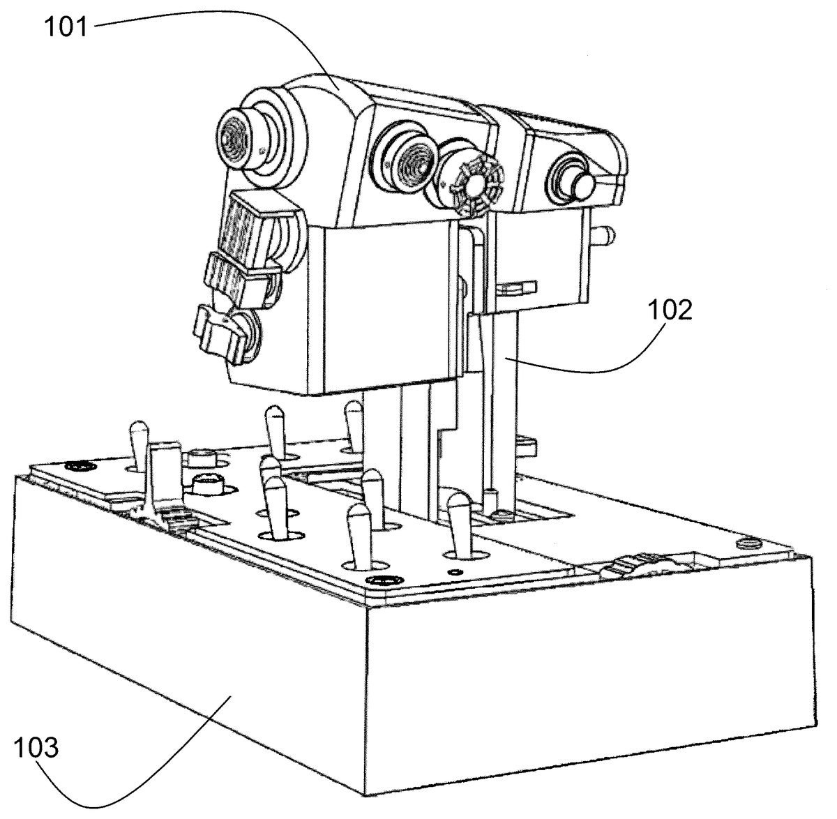
According to the cases, such a controller can include a single arm, making it possible to control all of the engines of the simulated craft, or two arms mounted in parallel, making it possible respectively to control the engine or engines of the left side and of the right side.FIG. 1is a view in perspective of such a game controller with two mobile arms, implementing the invention, according to the embodiment described in what follows.
Such a controller therefore includes two arms101,102, allowing the gas to be controlled (“throttle”). It can be a part of a system for flight simulations, and can be accompanied by a stick.
Each arm101,102, of the throttle comprises at its top a handle which incorporates a substantial number of actuators, mini-sticks, buttons and switches in order to allow the pilot to control a maximum of items without releasing the controls of the craft: this is the “Hands on Throttle And Stick” concept.
The arms101,102are mobile in relation to a base103, also provided with various buttons and adjusting elements.
As explained in what follows, the two arms101,102can be either integral, so that a single action controls all of the engines in an even manner, or non-integral, in order to be displaced independently in relation to one another.
FIG. 2is a partial cross-section view of one of the arms of the game controller ofFIG. 1. This can also be, in the case of a simpler controller with a single arm, the single arm of such a controller.
This game controller is therefore described in what follows within the framework of a use as a throttle in a flight simulation video game. Of course, this game controller can be used in other types of video games, for example in order to simulate the control of a land or sea vehicle.
As shown inFIG. 2, the throttle1comprises a base2whereon is mounted mobile in rotation an arm3according to an axis4of rotation. The mobile arm3can be displaced by a user over a nominal range of displacement delimited by two extreme positions (visible inFIG. 3), i.e. a minimum position5, corresponding to the stopping of the engine or engines and a maximum position6, corresponding to a maximum power of the engines.
The mobile arm3is provided with a lug7of which the lower surface hugs the shape of the surface8of displacement of the base2, defining a guide rail for the lug. This lug7can therefore be displaced along the surface8between the minimum position5and the maximum position6according to whether the arm3is displaced according to the “+” or “−” direction of displacement. InFIGS. 2 and 3, the lug7is in the default position (in other words, its lower surface is in contact with, or slightly separated from, the surface8) and is substantially located between the two extreme positions5,6.
In the embodiment described in relation withFIGS. 2 and 3, the base2(and more precisely the surface forming the rail8) is provided with two intermediary stops, i.e. a first stop10(called the “gas cut off” stop) and a second stop20(called the “afterburner” stop) able to cooperate with the lug7of the arm3and defining two intermediary locking positions of the lug7(and therefore of the arm3) in the vicinity of the extreme positions5,6.
The use of two stops makes it possible to obtain three zones, or sub-ranges, for the operation of the throttle, i.e. a zone21called “afterburning”, a zone22called “progressive acceleration” and a zone23called “gas cut off”.
In this example, the first stop10is fixed and the second stop20, which shall be described in more detail in relation withFIGS. 5 to 7can be removed and/or retracted. According to the embodiments, it is possible that the two stops be fixed, removable or retractable, or that a single one of the two stops is present.
When the mobile arm3is displaced and the lug7, which is then located in a default position (position that it taken when no action other than the displacement in rotation is exerted), enters into contact with one of the stops10,20, the mobile arm is then blocked in rotation. As such, during flight simulation (i.e. after having started the engines, as explained hereinafter), the user can displace the arm only over a reduced range, excluding the gas cut-off and afterburner zones. He remains in the progressive acceleration zone, and must carry out an additional manipulation in order to reach the other two zones.
As such, the crossing of the stop by the lug7, in order to continue the movement of the mobile arm3in its travel and switch to afterburner or gas cut off, is accomplished via an action of the user on the mechanical means of crossing which allow the lug to leave its default position.
According to the embodiment of the invention shown inFIG. 4, the mobile arm3comprises two portions connected together by a slide joint. A first portion31is the shaft of the mobile arm with a pivot connection in relation to the axis of rotation and a second portion32is the handle (more generally the outside shell) of the mobile arm whereon is fixed the lug7. Means of recalling (not shown) tend to return the lug7into a default position, wherein the crossing of said stops is not possible.
As such, when the lug7arrives in contact with one of the stops, it is up to the user to raise said handle if he wishes to continue the travel of the mobile arm3. When the user raises the handle, said lug7leaves its default position (in contact or in the vicinity of the surface8) and can pass over the stop with which it was in contact.
As can be seen inFIG. 3, the stop10is substantially punctual, and if, for example, the user raises said handle to switch from the zone22to the zone23, the lug7returns in the extension of the zone22, when it is located in the zone23. This means that the arm3has returned to its idle position, under the effect of the means of recalling. As such, when the engines are cut off (zone23), the user must cross the stop10in order to start the engines. There is no risk of an untimely start-up, and a specific action on the arm is required (lift and then push) in order to start.
On the other hand, the stop20remains raised over the entire zone21. This allows the user to have a feeling of the afterburner via the arm (the handle is maintained in its actuation position of the lug). In addition, it is as such possible to decelerate directly, by pulling the arm, without having to carry out a specific action (contrary to what is carried out in order to start the engines).
According to an embodiment described in relation withFIGS. 5 to 7, the second stop20of which the profile is shown inFIG. 5can be reversed and can be lodged in a housing9of the base according to two different positions:a position corresponding toFIG. 6, wherein the stop20is said to be “active”, i.e. it can enter into contact during the rotation of the mobile arm3, with said lug7, if the latter is placed in its default position in order to prevent the crossing of it;a second position corresponding toFIG. 7, wherein said retractable stop20is called “inactive”, i.e. it cannot enter into contact during the rotation of said mobile arm3with said lug7(even if the latter is placed in its default position). It has a surface that extends the surface8.
To switch from one position to the other, the user, in this embodiment, extracts the retractable stop by pulling on the grasping zone201, pivots it 180 degrees around a vertical axis and reintroduces it into the housing9.
This allows the user to be able to have the stop20in its “inactive” position if the simulation that he is using does not provide “afterburner”.
Note that inFIGS. 2 and 3, the retractable stop is mounted in the base in active position.
In order to allow the lug7to cross the stops10and20, in this embodiment, the invention therefore provides that the user raises a portion of the mobile arm3.
However, other solutions can be considered in order to allow the lug to leave its default position, for example:a mechanical system (utilising for example a means of actuating located on the handle of the mobile arm) allowing the lug7to be displaced laterally in relation to the mobile arm3so that the lug7can no longer enter into contact with the stop10or20;a mechanical system (utilising for example a means of actuating located on the handle of the mobile arm) allowing the lug7to be displaced longitudinally in relation to the mobile arm3so that the lug7can no longer enter into contact with the stop10or20;a mechanical system making it possible to displace the entire mobile arm3laterally so that the lug7linked to the mobile arm3can no longer enter into contact with the stop10or20;a mechanical system making it possible to pivot the entire mobile arm3around its longitudinal axis so that the lug7linked to the mobile arm3can no longer enter into contact with the stop10or20;a mechanical system making it possible that it is the removable stop that is displaced (by translation or by rotation) by actuating a mechanical system either laterally or vertically, in order to no longer present an obstacle to the passing of the lug7(the stop is thus retractable).
According to another embodiment, the second stop20is removable and can:either be lodged in a housing9of the base, wherein the stop20is said to be “active”, i.e. it can enter into contact during the rotation of the mobile arm3, with said lug7, if the latter is placed in its default position in order to prevent the crossing of it;or removed from the housing9of the base, wherein the stop20is said to be “inactive”, i.e. it cannot enter into contact during the rotation of said mobile arm3with said lug7.
Thus, if the simulation used by the player does not provide afterburner (as in the case of a simulation of the piloting of a civil aircraft or liner for example), the user can remove the stop20from the housing9. Since the housing9is empty, there is no intermediary locking position for the afterburner (in other words, there is no security against the triggering of the afterburner).
Conversely, if the simulation used by the player does provide for afterburner (as in the case of a simulation of the piloting of a fighter plane for example), the user can insert the stop20in the housing9so that an intermediary locking position is created. When the stop20is correctly positioned in its housing9, the lug7of the mobile arm3can enter into contact with the stop20when the arm3is rotated, provided that the lug is in its default position, thus creating an intermediary locking position.
Consequently, such a game controller increases the realism of the simulation. The simulation is realistic whatever the plane simulated by the video game.
Moreover, means for adjusting can be considered, in particular for the position and/or the height of the stops and/or of the lug.
According to a particular embodiment, the measuring of the displacement, and for example of the rotation, of each arm (or of the single arm according to the cases) is done by a Hall effect detection unit, implementing on the one hand at least one permanent magnet, and on the other hand at least one Hall effect sensor.
For example, in the case of a controller with two handles such as shown inFIG. 1, it can be provided that a magnet be integral with each arm, and is therefore mobile in relation to the base, whereto are fixed two sensors associated respectively to each arm.
FIG. 8shows, in the case of such a game controller with two throttles, an example of mobile arms34and35associated to the two handles respectively. Permanent magnets36and37are fixed on the arms34and35respectively. Hall effect sensors38and39integral with the base are placed across from these magnets36and37, in order to measure the position of the arm or arms in relation to the base.
As shown inFIG. 9, in this embodiment, means30are provided in order to render integral or not the two arms, according to the needs of the user. The latter has as such two simulation positions:
an integral position, wherein the two handles systematically follow the same movement (it is as such possible to act on a single handle to identically control the power of all the engines, for example in the case of the simulation of a twin-engine or four-engine craft);
a non-integral position, wherein the two handles can be displaced independently, which makes it possible for the user to control independently, for example the engine or engines on the left and the engine or engines on the right.
The means30can be comprised of a latch301, of which the general shape is cylindrical, located on the handle associated to the mobile arm35able to be housed in a housing302intended to receive the end of the latch301. This housing302is located on the handle associated to the mobile arm34. The user actuates the latch31(in a transversal movement) by the intermediary of the transversal protrusion3011.
More precisely, according to a particular embodiment, a lateral cover of one of the mobile arms34makes it possible to access a housing intended to receive the end of the latch. This housing is substantially cylindrical, but its mouth can be expanded in order to facilitate and/or guide the insertion of the end of the latch which protrudes from the other mobile arm35. The latch consists for example of a cylinder carrying a transversal protrusion allowing for the grasping. The ends of the cylinder are more preferably chamfered. The cylinder comprises a circular shoulder arranged in the cylinder. This shoulder receives an O-ring seal. The mobile arm35comprises a cylindrical housing receiving the cylinder of the latch and an opening for the protrusion of the latch (grasping protrusion). The opening made in the mobile arm35has an “L” shape. The latch is mobile in rotation in this cylindrical housing and slidably mobile according to an axis that is substantially parallel to the axis of rotation of the mobile arms34,35. The protrusion of the latch presses against the walls of the opening, which limits the amplitude of the rotation of the latch and the amplitude of the sliding. The O-ring seal prevents undesired sliding.
According to another aspect of the invention, which can where applicable be implemented independently of the aspects described hereinabove, means for adjusting the force to be applied on the handle or handles in order to displace them can be provided. It is indeed necessary that a handle retain its position when the user releases it. For this, means applying a force of friction on the arm make it possible to maintain the position of the arm, and to apply a mechanical resistance.
Furthermore, according to this particular aspect, the user can adjust this friction force, according to his needs or habits.
FIG. 10shows a particular embodiment of such means of adjustable friction which make it possible to more or less slow down the displacement of the two arms34,35. A thumbwheel40, accessible in the front of the controller, allows the user to mechanically increase or decrease the force of friction applied on the arms34,35. This thumbwheel40can rotate in relation to the base2of the controller, and acts on a shaft41. The end of this shaft41of this thumbwheel40is threaded, forming a worm screw411, and carries a slide50.
This slide50is in a link with two pistons51and52(in the case where there are two handles) each carrying a jaw (jaw53associated with the piston51, the jaw associated to the piston52not being visible in the figure). This jaw53supports a rubber pad55intended to enter into contact with the arm34.
The pad55can have a concave shape, cooperating with a friction zone of convex shape57integral with the arm34, in the manner of a hybrid combination of a vice comprising only one mobile jaw and a railroad shoe-brake.
As such, there is a worm screw mechanism411which displaces the slide50linked with the pistons51,52in order to apply in an absorbed manner the pads of the jaws on a friction zone of the arms. The pistons51,52are mounted slidingly in relation to the slide50, and are separated from the latter by one of the elastic parts61,62, which can be, for example coiled springs. The elastic part61acts in compression between the slide50and a shoulder formed on the piston51. The elastic part62acts in compression between the slide50and a shoulder formed on the piston52.
Each of said elastic parts61,62exerts on a shoulder formed respectively on the pistons51,52a pressure that is substantially proportional to the number of turns of the screw, and therefore to the turns applied by the thumbwheel. The jaw of each piston as such exerts this pressure on the friction zone of the arm.
Other means of adjusting the friction can of course be considered, for example using one or several cams that can apply a variable force on the arm or arms.
FIG. 11is a view of the two mobile arms340,350of the controller according to a particular embodiment of the invention. A removable bar70(which is represented on its own onFIG. 12) is fixed by screws on the base between these two arms340,350.
FIG. 13illustrates the profile of the afterburner second stop20according to another embodiment. This stop, which is removable and reversible, is located underneath the bar70, in a housing of the base located between the two arms340,350. The bar70forms a removable hood for the rail80and the stop20(the bar also prevents the inopportune removal of the stop20from its housing). To access the stop, it is necessary to remove first the bar70by unscrewing beforehand the two screws71using an Allen Key in this example.
FIG. 14illustrate the mounting by default in an inactive position of the stop20ofFIG. 13between the two arms340,350ofFIG. 11. The stop20is located in its housing which is situated between the two arms340,350and arranged in the rail80. The end of the stop which is the less high is thus located at a height equal (it is level) or slightly inferior to the height of the surface forming the rail80. In other words, the top surface of the end of the stop20which is the less high is located at the same level than the surface of the rail80(as a consequence, the lugs of the arms340,350thus cannot come into contact with this end during the rotation of the arms).
The stop20comprises a grasping surface or zone, in the form of a vertical plane, which facilitates its removal by the player from the base (or its insertion in the base). To do so, the player pinches the vertical plane201between two of his fingers and removes the stop20.
As it is represented onFIG. 13, the stop20is located outside the housing of the base located between the two arms340,350ofFIG. 11, and is thus inactive.
FIG. 15illustrates the mounting of the stop ofFIG. 13in an active position in the housing located between the two arms340,350ofFIG. 11.
In order to pass from the inactive position ofFIG. 14to the active position ofFIG. 15, the user extracts the retractable stop (by pulling on the grasping zone201illustrated onFIG. 13), pivots it 180 degrees around a vertical axis and reintroduces it into its housing (which is located between the two arms340,350and arranged in the rail80) in such a manner that it is its higher end that is present in relation to the surface of the rail80(so that the end of the stop20sticks out in relation to the surface of the rail80and thus the lugs of the arms340,350may come into contact against this part of this end sticking out when the anus are rotated).
In order to pass from the inactive position ofFIG. 13to the active position ofFIG. 15, if need be, the removable bar illustrated onFIG. 11as it is mounted between the two arms340,350, is first unscrewed by loosening the screws71, then removed, then kept aside. The stop20is inserted in its housing (which is located between the two arms340,350and arranged in the rail80) in such a manner that it is its higher end that is present in relation to the surface of the rail80(so that the end of the stop20sticks out in relation to the surface of the rail80and thus the lugs of the arms340,350may come into contact against this part of this end sticking out when the arms are rotated). The removable bar70can then be reinstalled and screwed between the two arms340,350by tightening the screws71.
Advantageously, the width of the vertical plane201is sufficiently low so that the respective lug of the mobile arms340,350does not come into contact against this plane201, including during the crossing of the stop20(the latter being in an active position) when the player wishes to position the arms340,350in the afterburner position (between the stop intermediate position and the extreme maximal acceleration position).
In other words, the width of the vertical plane201is chosen so that the lugs of the mobile arms340,350go past each side of the vertical plane201without coming into contact with this plane201.
Claims
- Game controller having at least one arm mobile in relation to a base, over a nominal range of displacement between two extreme positions, referred to as minimum position and maximum position respectively, characterized in that it implements at least one stopping mechanism of said at least one arm in an intermediary locking position, between said extreme positions, having a first contact surface integral with said base able to cooperate with a second contact surface integral with said at least one arm, in such a way as to define a reduced range of displacement of said at least one arm in relation to said nominal range of displacement, and means of crossing said intermediary locking position, able to take at least two states: a stop-state, wherein said first and second contact surfaces come into contact with each other, in said intermediary locking position;a crossed-state of said intermediary locking position, wherein said first and second contact surfaces are separated from each other by a predetermined action of a user, in order to allow said at least one arm to be displaced over an additional range of displacement of said reduced range of displacement, and in that at least one of said contact surfaces is formed over a removable and/or retractable element that is able to take two positions, an active position, wherein said at least one stopping mechanism in said intermediary locking position is active, and an inactive position, wherein said at least one stopping mechanism is inactive.
- Game controller according to claim 1 , characterised in that said removable and/or retractable element is mounted reversibly in said base.
- Game controller according to claim 1 , characterised in that said second contact surface is mobile according to an axis parallel to an axis defined by said at least one arm.
- Game controller according to claim 3 , characterized in that said at least one arm comprises two portions connected by a slide joint, a first portion corresponding to a shaft of said at least one arm and a second portion carrying an actuating element of said means of crossing, allowing for the switching from said stop-state to said crossed-state, means of recalling tending to return said means of crossing into said stop-state.
- Game controller according to claims 1 , characterised in that said at least one aim is mounted mobile in rotation in relation to said base.
- Game controller according to claims 1 , characterized in that said at least one arm is mounted mobile in translation in relation to said base.
- Game controller according to claims 1 , characterised in that said second contact surface is formed by one of the elements belonging to the group including: a portion of the corps of said at least one arm;a lug formed on said at least one arm;a bolt carried by said at least one arm;a latch carried by said at least one arm;a roller integral with said at least one arm;a portion integral with said base;a lug formed on said base;a bolt carried by said base;a latch carried by said base;a roller integral with said base.
- Game controller according to claims 1 , characterized in that it comprises, for said at least one arm, two stopping mechanisms.
- Game controller according to claim 8 characterized in that it comprises: a first stopping mechanism which consists in a stop in the vicinity of said minimum position corresponding to a simulation of a stopping of engines of a simulated vehicle, and making it possible to avoid the simulation of an untimely ignition and/or extinction of the engines;a second stopping mechanism which consists in a stop in the vicinity of said maximum position, making it possible to simulate a post-combustion.
- Game controller according to claim 1 , characterized in that it comprises, for said at least one arm, a Hall Effect movement detection unit for detecting the movement of said at least one arm.
- Game controller according to claim 1 , characterised in that it comprises means of applying a force by friction on said at least one arm, opposing the displacement of the latter.
- Game controller according to claim 11 , characterised in that said means of applying a force by friction can be adjusted.
- Game controller according to claim 1 , characterised in that it comprises two arms, and means for rendering said arms integral/non-integral, in such a way that their displacements can be linked or independent.
- Game controller according to claim 1 , characterised in that said removable and/or retractable element comprises at least one grasping zone.
Disclaimer: Data collected from the USPTO and may be malformed, incomplete, and/or otherwise inaccurate.