U.S. Pat. No. 8,696,459
MEASUREMENT AND SEGMENT OF PARTICIPANT'S MOTION IN GAME PLAY
Issue DateMay 14, 2012
Illustrative Figure
Abstract
Systems and methods are provided for the measurement and input of position information and/or information regarding the position and/or movement and/or speed of a target of interest, e.g., without requiring a hand-held controller. According to further aspects of the present invention, systems and methods are provided for removing background images, such as furniture and other items, shadows, etc., in the environment of an associated camera or cameras. The elimination of background images behind the subject reduces processing requirements to track the movements of a participant, and may avoid the potential of the image processing logic to confuse the background with the image of the subject. Parabolic LEDs are also provided, which provide safe illumination and gating. As an alternative to gating, a grating or grid light source may be utilized. Still further, a participant's image may be integrated into video applications including games.
Description
DETAILED DESCRIPTION According to various aspects of the present invention, systems and methods are provided for the measurement and input of position information and/or information regarding the position and/or movement and/or speed of a target of interest, e.g., a video game participant's palms, hands, feet, legs, head, etc., without requiring a hand held controller or other position determining device located on the target of interest. Thus, for example, a participant may interact with a video game and/or other interactive virtual computer application without requiring the participant to hold onto a controller. Rather, the participant may utilize their hands, feet and/or other body parts for interaction, e.g., to play a game or to respond to displayed electronic events. For example, a participant may use their hands to play virtual basketball or virtual boxing, their feet to play virtual soccer, football or dance, etc., without requiring the participant to grasp implements, e.g., controllers, game sticks, handlers, etc. Moreover, a participant may interact in virtual worlds or other non-game virtual realms without requiring a hand-held controller. Of course, a hand-held controller may be utilized, e.g., where such a device comprises part of the game or virtual computer application experience. According to further aspects of the present invention, systems and methods are provided for removing background structures, such as furniture and other items in the environment of an associated camera, from interfering with a detected image of a target of interest. The elimination of background images including shadow behind the subject reduces processing requirements to track user movement and may avoid the potential of the image processing logic to confuse the background with the image of the target of interest. In order for the system to measure position and/or movement, e.g., to know if the participant's hands are moving forward or back, left or ...
DETAILED DESCRIPTION
According to various aspects of the present invention, systems and methods are provided for the measurement and input of position information and/or information regarding the position and/or movement and/or speed of a target of interest, e.g., a video game participant's palms, hands, feet, legs, head, etc., without requiring a hand held controller or other position determining device located on the target of interest.
Thus, for example, a participant may interact with a video game and/or other interactive virtual computer application without requiring the participant to hold onto a controller. Rather, the participant may utilize their hands, feet and/or other body parts for interaction, e.g., to play a game or to respond to displayed electronic events. For example, a participant may use their hands to play virtual basketball or virtual boxing, their feet to play virtual soccer, football or dance, etc., without requiring the participant to grasp implements, e.g., controllers, game sticks, handlers, etc. Moreover, a participant may interact in virtual worlds or other non-game virtual realms without requiring a hand-held controller. Of course, a hand-held controller may be utilized, e.g., where such a device comprises part of the game or virtual computer application experience.
According to further aspects of the present invention, systems and methods are provided for removing background structures, such as furniture and other items in the environment of an associated camera, from interfering with a detected image of a target of interest. The elimination of background images including shadow behind the subject reduces processing requirements to track user movement and may avoid the potential of the image processing logic to confuse the background with the image of the target of interest.
In order for the system to measure position and/or movement, e.g., to know if the participant's hands are moving forward or back, left or right, and fast or slow during a video game, e.g., boxing, or other interactive virtual application, a system must be able to measure the distances, angles and speeds of movement initiated by each player. According to various aspects of the present invention, systems and methods are provided, which trace or otherwise track a participant, e.g., by identifying the position (distance), movement direction (angle) and/or speed of movement of the hands, feet, head, body, etc., of the participant in a limited 3-D space. This capability provides complete freedom to participate in games and/or to respond to other types of events in an interactive virtual environment without requiring the participant to wield hand controllers or other position determining tools.
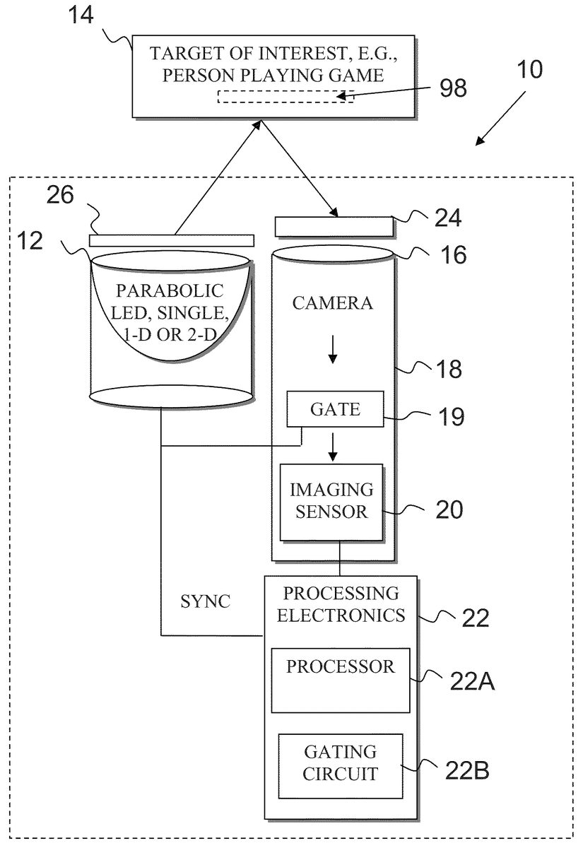
Referring now to the drawings, and in particular, toFIG. 1, according to various aspects of the present invention, a system10comprises at least one illumination source12to illuminate a target of interest14, e.g., a participant interacting with a video game or other virtual interactive application. As an example, the illumination source(s)12may be implemented using one or more parabolic invisible light emitting diode(s) (PLED or parabolic LED) that emit a collimated thin beam or slightly divergent beam, which can be directed to illuminate a target of interest14. Parabolic LEDs will be described more fully herein.
The light emitted from the illumination source12is received at a light receiving lens16of an associated camera18, such as a color or black and white webcam. An optional gate19of the camera18may selectively enable the light entering the camera18to be converted into an image using a suitable image sensor20. The image sensor20may be implemented using a focal plane array or other suitable imaging technology. The output of the image sensor20is then coupled to processing electronics22, which process the image obtained by the image sensor20to derive a digital representation of a target of interest. For example, the processing electronics22may comprise hardware such as a processor22A and any required supporting electronics and optional software for implementing the necessary processing, e.g., 3-D computations from the image information obtained by the image sensor20. The processing electronics22may also control features of the system such as a gating circuit22B or other processing that is utilized to facilitate measurement of the participant's movement in a limited 3-D space as will be described in greater detail herein.
For example, as will be described in greater detail herein, the processor22A may be coupled to the image sensor20and may be configured to generate a digital representation of the target of interest, e.g., by determining the position, movement, speed, direction, etc. of the target of interest, such as a participant of a video game or other interactive virtual computer application. The processor22A may be further configured to measure the time of flight of the light emitted by the illumination source(s)12to measure the distance to the target of interest and to combine the time of flight measurement information with the two-dimensional image data obtained by the image sensor of the camera to generate a three dimensional information with regard to the target of interest.
A filter24may also be provided optically in front of either the light receiving lens16or the image sensor20of the camera18to block light in spectral bands that are not of interest. In this regard, the filter24may be integrated with the camera18or the filter24may be a separate filtering arrangement positioned relative to the camera18. For example, the filter24may reject light in spectral bands defined by the bands of anticipated fluctuating visible ambient light. Alternatively, the filter24may be transmissive to light only in the frequency range (or ranges) of the corresponding illumination source(s)12. AlthoughFIG. 1illustrates only a single filter positioned optically forward of the light receiving lens16, it is understood that other/alternate filters and/or filter locations may also be utilized to filter the signal before the light reaches the image sensor20. The processing electronics22may also/alternatively implement software filtering of the image collected by the image sensor, should such processing be necessary for a given application.
By way of illustration, the illumination source(s)12may emit near infrared (NIR) light, ultraviolet (UV) light or other invisible or substantially invisible light. Keeping with the above-illustrative exemplary NIR light-emitting sources12, the filter24may comprise a plastic/glass NIR filter or a piece of developed negative film that is positioned in the front of the light receiving lens16or the imaging sensor20of the camera18. As another illustrative example, the camera18may include a built-in visible light (VIS) cutoff filter that is suitably positioned along an optical path to block VIS light. In this example, the image sensor20is correspondingly sensitive to NIR light. In this regard, light detected by the camera18will be insensitive to dynamically changing visible light because the light detectable by the image sensor20defines a spectral range that is outside the range of anticipated fluctuating visible ambient light.
According to various aspects of the present invention, an optional diffuser26, may be utilized to scatter the light from an associated illumination source12into many directions to reduce a shadow cast by a corresponding object, as will be described in greater detail below.
According to further aspects of the present invention, and as will also be described in greater detail below, a plurality of cameras18, e.g., two cameras18, which can be implemented as discrete cameras or a single stereo camera/webcam, etc., may be coupled to the processing electronics22. For example, a stereo camera may be utilized to measure the distance, angle and/or speed of the participant's hands, feet and body movements on the image sensor20, e.g., a focal plane array of the stereo camera22. Alternatively, image information from two cameras can be combined by the processing electronics22to render 3-D information.
Referring toFIG. 2, for a conventional LED30, a significant portion of emitted light is wasted in its backward propagation. Moreover, the forward propagating angle of light emitted from a conventional LED is too large. Therefore, the intensity density of a conventional LED is too low and the distance is too short for the LED to be practical for illumination of a participant, e.g., a player of a video game who may be positioned several feet from the illumination source.
Parabolic LED Light Source:
As noted above, one or more illumination sources12may be implemented as a parabolic LED. Referring toFIG. 3, a parabolic LED12is illustrated according to various aspects of the present invention. The parabolic LED12comprises a convex parabolic model32and a concave parabolic reflector34. For example, the convex parabolic model may be about 10-20 mm in dimension. The concave parabolic reflector34may comprise, for example, a stamped-on plate of thick heated plastic. A thin layer of aluminum may be coated over the plate to increase the reflectivity.
The parabolic LED12is configured such that an LED die36is positioned at the focal point of the parabolic reflector34. Two legs38,40provide a path for the die36to receive DC power (+ and −) from a suitable power supply and corresponding circuitry (not shown). For example, the legs may comprise two generally r-shaped legs that are glued or welded on the outer surface of the cylinder that houses the LED die36and corresponding parabolic structures. The legs38,40are then attached, e.g., via welding, to the LED die36. Moreover, a component such as a transparent epoxy may be injected into the LED to cover the LED die36and the corresponding concave parabolic space, e.g., to prevent oxidizing of the die36. A component such as epoxy may further hold the die36in a secure manner.
According to various aspects of the present invention, the parabolic LED12is capable of collecting the backwards light from the die. Moreover, the parabolic LED12may be capable of generating an almost collimated beam. As such, a high intensity and long distance illumination light may be obtained. According to further aspects of the present invention, the beam angle may be adjusted by positioning the die36so as to align at a position other exactly on the focal point.
Referring toFIGS. 4 and 5, an exemplary implementation of a parabolic LED12according to various aspects of the present invention is compared to a convention LED30. The parabolic LED12and conventional LED30are placed at the same line on a table. Additionally, the same voltage of 3V is applied to both the parabolic LED12and the conventional LED30to illuminate a wall that is located the same distance from both the parabolic LED12and the conventional LED30.FIG. 4illustrates that the output from the parabolic LED12is a powerful and almost collimated beam without significant backward light and the output from the conventional LED30is a low-intensity divergent beam with backward light. Similarly,FIG. 5illustrates that the output from the parabolic LED12forms a small concise beam spot and the conventional LED forms an indistinct large spot. According to various aspects of the present invention, the parabolic LED12may be capable of approximately 20 times smaller spot diameter and 30 times longer distance than the conventional LED30.
The parabolic LEDs12may further implement any of the features as described more fully in U.S. Provisional Patent Application Ser. No. 61/058,798, entitled “MEASUREMENT AND SEGMENT OF PARTICIPANT'S MOTION IN GAME PLAY” filed Jun. 4, 2008, U.S. Provisional Patent Application Ser. No. 61/058,790 filed Jun. 4, 2008 entitled “A CONSTANT AND SHADOWLESS LIGHT SOURCE”, and corresponding U.S. patent application Ser. No. 12/478,515, entitled “A CONSTANT AND SHADOWLESS LIGHT SOURCE”, the disclosures of which are incorporated by reference in their entirety.
Moreover, the parabolic LED12may output invisible light (although it can output ultra violet or visible light), or at least light in a spectral range that is insensitive to anticipated dynamic ambient visible light from a corresponding environment. Also, the parabolic LED12may be utilized in a shadowless configuration with the corresponding camera18as described more fully in U.S. Provisional Patent Application Ser. No. 61/058,790 filed Jun. 4, 2008 entitled “A CONSTANT AND SHADOWLESS LIGHT SOURCE” and corresponding, U.S. patent application Ser. No. 12/478,515, entitled “A CONSTANT AND SHADOWLESS LIGHT SOURCE.”
In this regard, the parabolic LED12may implement an illumination source that is capable of emitting light into an environment where the emitted light is in at least a first predetermined frequency band that defines a spectral range outside the range of anticipated fluctuating ambient light. Referring back toFIG. 1, under this arrangement, the optional filter24is configured to substantially block light in an anticipated spectral range fluctuating ambient light and/or be transmissive only to light generally in the first predetermined frequency band from the PLED. Similarly, the optional diffuser26may be positioned optically in front of the parabolic LED(s)12to diffuse the light emitted thereby as described more fully in U.S. Provisional Patent Application Ser. No. 61/058,790 filed Jun. 4, 2008 entitled “A CONSTANT AND SHADOWLESS LIGHT SOURCE” and corresponding U.S. patent application Ser. No. 12/478,515, entitled “A CONSTANT AND SHADOWLESS LIGHT SOURCE.”
Measurement of Participant's Motion Using Range-Gating Segmentation:
Referring toFIG. 6, a method50is provided to measure movement, e.g., of a player interacting with a video game according to various aspects of the present invention. A thin LED beam, e.g., using the parabolic LED12described more fully herein, may be utilized to make a 2-D fast raster scan for a player or participant at52, or a 1-D parabolic LED array vertically placed may be utilized to make a 1-D fast raster scan for the player at52. A 2-D parabolic LED array may also be utilized to illuminate the player at52without scan. The light from the beam is collected by a detector such as a camera at54, and a 2-D image position, e.g., of a hand of the player, may be generated on an image sensor at56. For example, light may be collected by the camera18and the collected light may be imaged using the image sensor20, e.g., a 2-D Charge Coupled Device(CCD), intensified Charge Coupled Device (ICCD) or other suitable image sensor.
To obtain distance information, such as the distance to the hand of the player, and to further determine dynamic movement information, e.g., is the hand moving forward or backward, etc., the time of flight of a beam from at least one illumination source is measured at58. From the time of flight data, 3-D information may be computed and a 3-D image may be obtained at60.
As an example,FIG. 7illustrates an implementation of the system10that utilizes a plurality of illumination sources12, e.g., parabolic LEDs arranged in a configuration that surrounds the camera lens16of the camera18. Although illustrated as a generally annular ring of illumination sources that surround the light receiving lens16of the camera18other configurations and number of illumination sources12may alternatively be utilized. Moreover, according to various aspects of the present invention, the illumination source(s)12are arranged proximate to the camera lens16so that the light receiving lens16receives light from the at least one illumination source at a sufficiently small angle so as to at least substantially reduce detected shadows of the illuminated target of interest. In this regard, the light that originates from the illumination source(s)12is proximate to the camera lens16and can be approximated as light that is “almost” from the camera lens16, itself.
Also as noted above, an optional diffuser may be utilized to scatter the light from an associated illumination source12into many directions to reduce a shadow cast by a corresponding object. Under this arrangement, the optional diffuser26may be implemented as a generally “donut-shaped” configuration that is positioned so as to diffuse light from the illumination sources12. Moreover, the diffuser26may be positioned so that it is not in an optical path of the light entering the lens16of the camera18. However, the diffuser26may not be used according to various aspects of the present invention.
Lettrepresent the time required for the illumination source(s)12, e.g., parabolic LEDs, to launch light and receive the light back at a detector, e.g., the image sensor20of the camera18, where the received light is from the target, e.g., the hand of the player of the video game. Letdrepresent the distance from the illumination source(s)12and corresponding camera to the target. Under this arrangement, the distance from the target to either the illumination sources12or camera18is approximately the same because the illumination sources12are surrounding the camera18as illustrated inFIG. 7. Alternatively, a single illumination source12may be utilized, which is positioned proximate to the circumference of the light receiving lens16of the camera18. In this regard, the distancedfrom the illumination sources12and/or camera18to the target is:
d=ct/2
where c is the speed of light.
Therefore the 3rd dimension information d of the participant's movement can be obtained. Since the image sensor20, e.g., a focal plane array (FPA) can obtain a 2-D image of the participant, a 3-D profile of the player can be constructed over time.
In this regard, software, e.g., executed by the processing electronics22, may be utilized to compute 3-D information at60. For example, the software may calculate the time of the target (such as hand) moving from one location to the other location to obtain the speed of the participant's movement. Moreover, time of flight information may be utilized to compute angle, orientation and direction information necessary to make 3-D determinations required by the video game or other interactive application.
Referring toFIG. 8, a method70provides an alternative to the method50described with reference toFIG. 6to measure movement, e.g., of a player interacting with a video game, according to further aspects of the present invention. A pulsed divergent LED beam provided by a LED lamp is utilized at72to illuminate a target, e.g., a player interacting with a video game or other interactive application. A gated camera synchronizing with the pulsed LED is used to collect light from the beam at74and the collected information is utilized to generate a 3-D image at76.
For example, with reference back toFIG. 1, the processing electronics22may control gating circuitry22B, which is used to gate both the illumination source12, e.g., implemented as a divergent beam LED, and the gating circuitry may be used to control a gate19on the camera18.
Although a laser is capable of generating a fast pulse for gating, such a beam may be harmful, e.g., to the eyes of players or observers in the environment of the beam. Other light sources, e.g. incandescent bulbs, cannot generate pulses that are fast enough for gating. However, the LED techniques described more fully herein utilize semiconductor devices that are capable of generating a sufficiently fast pulse for gating that is not harmful to the eyes of players and observers in the environment.
In order to achieve a relatively high range of accuracy in generating the 3-D image, the LED must have narrow pulse width and a relatively high pulse repetition frequency. For example, a pulse width of approximately 200 picoseconds (ps) and a pulse repetition frequency (PRF) of approximately 32 kilohertz (kHz) may be utilized. Additionally, a relatively high-speed camera may be utilized. For example, a high-speed camera having gate times down to approximately 200 ps and delay steps down to approximately 100 ps may be utilized.
As noted in greater detail herein, various aspects of the present invention may be suitable for use with a parabolic LED capable of producing a thin beam and certain aspects may be suitable for use with an LED capable of producing a divergent beam. In this regard, range-gating segmentation may be utilized to obtain the 3-D image. For example, the camera18may be opened, e.g., via gate19, at tnfor a duration of Δt:
tn=t0+Δt
to get a slice (frame) of a 2-D target image on the image sensor20at a distance dnwith thickness Δd. Here, t0is the time required for a beam of light from the illumination source(s)12to travel to the target just before touching the target and Δt is the time required for the beam to cover the slice thickness Δd. Such time may comprise a time less than one nanosecond (ns) that corresponds to a spatial resolution of 15 cm. Thus, the camera gate19correspondingly should open for less than 1 ns. The pulse from the illumination source12must synchronize with the camera gating circuit. Similarly at tn+1=tn+Δt, the next slice image is obtained, and at tn+m=tn+m−1+Δt, the last slice or last frame image is obtained. By combining all slices/frames together, e.g., by the processor22, a 3-D target image may be generated as illustrated inFIG. 9.
By measuring the distance and time of the target (such as hand) at different positions, the moving direction, angle and speed information may be obtained. Further, by setting a short gating time surrounding the target, the participant's moving area may be constrained at least in one dimension, e.g., to within 1.5 to 3.5 m. As such, any background structures from the environment, e.g., a sofa, curtains, furniture and other environmental background behind the target/participant can be removed. Moreover, the participant's shadow can also be removed.
Referring back toFIG. 1, in certain applications, a retro reflective material98may optionally be associated with the participant. For example, where the game or virtual interactive computer application requires a controller or other device, such device may include a retro reflective material98. As a few illustrative examples, a retro reflection paint or similar materials can be applied to a controller, cloth, garment such as a glove or sleeve, playing tools, etc., that the participant will engage with, wear, etc. Still further, a retro reflection material98such as retro reflection tape may be stuck onto a controller or other suitable device.
Similarly, such retro reflection tape may be applied to cloth, a garment, playing tools, etc., that the participant will engage with, wear, etc. Still further, the retro reflective tape may be temporarily stuck to the participant, e.g., a body part, to reflect the light surrounding the camera back to the original path so the cameras can get good reference points to precisely measure the distance, angle and speed of the player/participant. For example, a retro reflective sticker attached to a hand, or attached to a glove or other suitable garment may provide more accurate positioning, especially where the retro reflective material reflects the light relatively efficiently back to the camera. Still further, retro reflective material98may be applied in multiple discrete locations, such as an elbow and hand of a participant. Such an arrangement provides two relatively high reflective surfaces for the processor22A to identify for determining position, movement, speed, etc.
Measurement of Participant's Motion Using a Stereo Camera/Multiple Cameras:
According to further aspects of the present invention, two cameras may be utilized together to provide a stereo camera or stereoscopic imaging system. Referring toFIG. 10, two detectors, which are separated by a known distance d, are positioned so as to have known look angles ∂ and φ.
When a point on the participant14is in the field of view (FOV) of both detectors, the angle between the two detectors is given by:
β=180−θ−φ
By using the law of sine:
A/sin ∂=L/sin β
Thus, the distance to the target14is determined by:
d=Asin φ=Lsin φ sin ∂/sin(180−∂−φ)
The accuracy of distance d (such as the participant's hand movement) depends on the accuracy of L, ∂, and φ. The detectors, such as cameras18may image the participant on their associated image sensor20, e.g., 2-D detector arrays. Thus, software, e.g., as executed by the processing electronics22including the processor22A may be utilized to measure the angles, directions, and distances and thus triangulate the positions of the body parts (hands, feet, and head) of the player in the 3-D space, e.g., on a pixel-by-pixel basis. Moreover, because the time of the distance change can be measured, the speed of the movement can also be determined. Still further, by setting a threshold d0, e.g., for a maximum distance, background images such as from fixed environmental features including furniture, lamps, etc., and from moving shadows detected at a distance further than the threshold d0can be removed from the video information.
FIG. 10also illustrates that a retro reflective material98may optionally be associated with the participant as noted more fully herein. For example, retro reflection paint or similar materials can be applied to a controller, cloth, garment, playing tools, etc., that the participant will engage with, wear, etc. Still further, a retro reflection material98such as retro reflection tape may be stuck onto a controller or other suitable device. Similarly, such retro reflection tape may be applied to cloth, a garment, playing tools, etc., that the participant will engage with, wear, etc. Still further, the retro reflective tape may be temporarily stuck to the participant, e.g., a body part, to reflect the light surrounding the cameras back to the original path so the cameras can get good reference points to precisely measure the distance, angle and speed of the player/participant. In this application, gating may not be not necessary to use.
Referring toFIG. 11, a system is illustrated which is analogous to that ofFIG. 10, except that a single stereo device is utilized in lieu of two independent devices. That is, the first and second cameras comprise a stereo camera such that the image sensor of the first and second cameras is implemented by a common image sensor to the stereo camera. For example, each camera shares a common image sensor20, which is coupled to the processing electronics22. In this implementation, the optional retro reflective material98may also be used. For example, the retro reflective material reflects the light surrounding the stereo camera back to the original path so the stereo camera can get good reference points to precisely measure the distance, angle and speed of the player/participant. In this application, gating may not be not necessary to use.
Various aspects of the present invention provide the ability to generate a digital representation of a target of interest, e.g., to measure positions of a target of interest such as the body parts of a video game player in real time. Accordingly, there is no requirement for a hand-held controller or other device to make position determinations, thus giving the participant more freedom, more convenience and a more exciting interactive experience.
As yet a further alternative, if there is no threshold d0for a maximum distance, e.g., where the player does not know how to determine or enter such information into the processing electronics22, then the stationary background may be subtracted out. For example, one frame picture for the stationary background may be obtained first, without the subject in the field of view of the cameras18, e.g., before the player enters the scene to start the game. During operation, the frame picture of the stationary background may be subtracted out from the video images thus removing the background information.
Moreover, as noted above, the system may be capable of reducing or eliminating moving shadows, e.g., using the techniques described more fully in U.S. Provisional Patent Application Ser. No. 61/058,790 filed Jun. 4, 2008 entitled “A CONSTANT AND SHADOWLESS LIGHT SOURCE” and corresponding U.S. patent application Ser. No. 12/478,515 entitled “A CONSTANT AND SHADOWLESS LIGHT SOURCE.” In this regard, any features or aspects of the above-incorporated references may be combined with aspects set out more fully herein. In this regard, the image sensor20according to various aspects of the present invention set out herein, may be unaffected by ambient visible light, including dynamically changing ambient visible light from a television (TV) monitor, computer monitor or fluctuating light cast upon a ceiling or wall, etc.
Moreover, unlike conventional games, according to various aspects of the present invention, the participant's image can be put on a screen92, e.g., by opening a window in an associated application. Other participant's image(s) may also be seen, e.g., by communicating image data across a network such as the Internet. Therefore two or more participants can see each other on their screen.
3-D Video Segmentation Using Gated Parabolic LEDs:
According to various aspects of the present invention, systems and methods are provided, which trace or otherwise track a body or object of interest in a 3-D space. For example, the system may identify the position (distance), movement direction (angle), orientation and/or speed of movement of the hands, feet, head, etc., of a participant of a video game or other electronic software application. This capability provides complete freedom to participate in games and/or to respond to other types of events in an interactive virtual environment without requiring the participant to wield hand controllers or other position determining tools unless such implements are required by the game itself.
As noted above, a plurality of cameras18, e.g., two cameras18such as illustrated inFIG. 10, which can be implemented as discrete cameras, or a single stereo camera/webcam, as illustrated inFIG. 11, may be coupled to the processing electronics22in order to generate 3-D information, e.g., by triangulating angle measurements obtained from a stereo camera and corresponding illumination sources. For example, a stereo camera may be utilized to measure the distance, angle and/or speed of the participant's hands, feet and/or body movements on the image sensor20, e.g., a focal plane array of the stereo camera22in a manner analogous to that set out with reference to the two-camera system ofFIG. 10.
In this regard, the illumination source(s)12associated with a first camera18may create a shadow for a second camera18, such as where the target cannot block the shadow created by the other illumination source(s). This can be seen because the first and second cameras18have a different illumination angle relative to the target14. However, since the two cameras18are utilized in a system, a trigger may be utilized for each camera18. In this regard, a first camera18and its associated illumination source(s)12are turned on and a second camera18and its illumination source(s)12are turned off. The trigger then toggles the state of each camera18such that the first camera18and its illumination source(s)12are turned off and the second camera18and its illumination source(s) are turned on, etc. The cycle speed may be set to obtain the desired quality of image. As an illustrative example, a cycle speed of approximately 60 Hertz (Hz) may be utilized by the trigger to toggle the action of each of the first and second cameras and their associated illumination source.
By way of further illustration, the processor22A may be used to control, e.g., modulate the parabolic LED(s)12and other appropriate components of the system in a manner that enables the left and right channels of a stereo camera18or first and second discrete cameras18to work independently in a manner that facilitates interleaving of image data by the processor22. As such, the parabolic LED illumination from a first one of the cameras18does not interfere with the image data received by a second one of the cameras, and vice versa.
For example, where two discrete cameras18are utilized, the corresponding parabolic LED(s) associated with a first camera18may be turned on and the parabolic LED(s) associated with the second camera18may be turned off. During this interval, the processor22A gathers two-dimensional image data from the first camera18, e.g., to collect one or more images and the second camera is not read. After a predetermined period, e.g., at least as long as the short pulse duration of the parabolic LED(s) of the first camera18, the parabolic LED(s) associated with the first camera18are modulated off and the parabolic LED(s)12associated with the second camera18are modulated on.
During this new interval, the processor22A gathers two-dimensional image data from the second camera18, e.g., to collect one or more images and the first camera is not read. Thus, the parabolic LED(s) of the first and second cameras18are modulated on and off in an alternating manner that interleaves the active (modulated ON state) of the parabolic LED(s) associated with each of the first and second cameras18(or left and right channels of a stereo camera18). Correspondingly, the two-dimensional image data from the first and second cameras18(or left and right channels of a stereo camera18) are selectively read in a manner commensurate with the pulses of their associated parabolic LED(s). Under this configuration, gating of the cameras themselves is not required. Rather, sufficient data to implement triangulation can be accomplished using the interleaving modulation of image data collection as the corresponding parabolic LEDs are modulated on.
As an illustrative example, assume that the parabolic LED(s) associated with the first camera18are modulated ON for a short pulse. The processor22A controls the first camera18, e.g., for a certain time duration from t1to t2=t1+δt, such that:
t1=2d1/c,
t2=2d2/c,
wherein d1is the predetermined closest distance of the target of interest14to the camera18, d2is the predetermined furthest distance of the target of interest14to the camera, δd=d2−d1is the limited moving area of the target of interest14, and c =3×10⁸m/s is the speed of the light. In this regard, the control electronics22does not read image data from the second camera.
Thus, the processor22A modulates the parabolic LED(s) ON at time zero and modulates the parabolic LED(s) OFF at time t2. Similarly, the processor22A reads the first camera18at time t1and stops reading the first camera18at time t2. The duration is computed as 2(d2−d1)/c. The above process can then be iterated.
Accordingly the operations of parabolic LED(s) and camera18may be synchronized. Since the pulse emitted by the parabolic LED(s) illuminates the target of interest14, e.g., a participant such as a player of a video game in the area from d1to d2, a stereo camera can obtain the participant's stereo image and measure the 3-D information of the participant, e.g., within a limited (and defined) three-dimensional space. Suppose that the participant will engage the system in the limited area from 1.5 meters (m) to 3.5 m from the camera18. In this example, the gate opening time is δt=2×2 m/c=13.4×10−9s=13.4 ns, which is a significantly long enough time period for the gating circuit22B to control the camera18for proper gating function.
In this regard, the light emitted from the parabolic LED(s) does not create adverse effects, such as to the participant's eyes (unlike conventional laser beams that are unusable in the context of the present example due to the potential harmful effects of conventional lasers on the eyes of the participants). Moreover, conventional incandescent light cannot emit short pulse light. Further the visible light of a conventional incandescent light will be affected by ambient conditions such as the TV screen, computer monitor, wall/ceiling light etc.
However, the parabolic LED(s) of the present invention may be implemented as a semiconductor diode that can have a switching time on the order of nanoseconds and can be controlled by the gating circuit22B. Moreover, as noted in greater detail herein, unlike a common LED beam (that has wide angle, low intensity and short distance), the beam emitted by PLED(s) can be collimated to reach long distance such as 3.5 m. Moreover, the invisible LED light of the PLED(s) may be constant and is not affected by visible ambient light.
As noted in greater detail herein, a single parabolic LED may form a 2-D raster scan a target of interest. Alternatively, a 1-D parabolic LED array may be utilized to implement a 1-D scan of the target of interest14, e.g., a video game player, as illustrated by the vertically stacked 1-D PLED array illustrated inFIG. 12. Alternatively, a 2-D parabolic LED array may be utilized to illuminate the player without requiring a scan of the player, as illustrated by the 2-D parabolic LED system illustrated inFIG. 13. Moreover, in certain implementations, the above-described gated parabolic LED12techniques may be used to remove the background and shadows that extend beyond a distance determined by d2. In this regard, a stereo camera18(or two discrete cameras) may be utilized to obtain the information necessary to generate necessary 3-D information from the 2-D images that have been processed to remove shadow and background noise.
According to further aspects of the present invention, 3-D information can also be derived from a single camera, such as by using segmentation techniques described more fully herein. For example, referring back toFIG. 1, the system10may comprise one or more invisible light parabolic LEDs12to emit a collimated thin beam or slightly divergent beam to illuminate the target of interest14. The light emitted from the parabolic LED(s)12that is reflected by the target of interest14, e.g., game participant, is received at the light receiving lens16of the associated camera18, which is configured to convert the invisible light from the parabolic LED(s)12into an image, e.g., using a suitable image sensor20with an optional filter24, such as a visible cutoff filter optically positioned in front of the lens16or image sensor20. The output of the image sensor20is coupled to a processor22A of the processing electronics22, which may also be utilized to control features of the system such as the gating circuit22B to facilitate the measurement objects of interest, such as the measurement of the participant's movement in the 3-D space.
In this regard, the parabolic LED(s) may be controlled by either the gating circuit22B or some other process synchronized to the gating circuit22B, to emit a short pulse beam, e.g., of invisible or near invisible light, thus illuminating a participant of a game or other interactive virtual software application. The optional gating circuit22B is configured to open the gate19of a corresponding camera18when the PLED(s) are modulated ON during a short pulse. As an illustrative example, the camera18may open and close several times from t1to t2or from d1to d2, such that several slices of the participant's image may be obtained for each parabolic LED pulse. Thus, the system may obtain 2-D images for discrete slices of time on the image sensor20. Additionally, distance information may be obtained by combining information derived from a series of 2D image slices together in a segmentation process. For example, two or more slices may be evaluated to determine the movement distance, angle, orientation, speed of detected movement, etc., of the participant in a defined 3-D space to facilitate interaction with a game or virtual application requiring a position determination.
However, the gate19of the camera18must be fast enough to implement video segmentation and the camera18must be sensitive enough to respond the short pulse of the parabolic LED(s), which may be less than 1 ns. As an illustrative example, the system10may utilize the gating circuit22B to control a crystal (not shown) to open and close the gate19of the camera18. In this example, the image sensor20may be implemented as a high gain or intensified Charge Coupled Device (CCD). Although the gating is very fast the video frame rate may be slow. For example, the frame rate may be adjusted to 30 frames per second (f/s).
Also, the camera18may be always on. In this exemplary configuration, the gate of the camera18opens and closes with a frequency that may be on the order of nanoseconds per frame. As such, the signal can be accumulated to achieve a reasonable signal to noise ratio. Still further, a Complementary metal-oxide-semiconductor (CMOS) sensor, e.g., CCD/CMOS sensor that is less sensitive than a typical intensified CCD (ICCD) may be utilized to improve the image collection response time of the image sensor20.
Referring toFIG. 14, according to further aspects of the present invention, the illumination of the target14may be implemented using a coarse grating or grid light source that illuminates a space using for example, a strong divergent point source. As an illustration, the illumination source12may comprise a small invisible or visible light source that illuminates a grid mask94(coarse grating) having a grid pattern96therein. This arrangement causes light passing through the grid pattern96of the grid mask94to project a light pattern into a defined space. The grid pattern is reflected back and is collected by the camera18and corresponding image sensor20.
As a participant moves within the defined space covered by the grid pattern, cells within the grid pattern96will be blocked from reflecting back to the camera18. Moreover, as the participant moves within the defined space, the number of cells that are blocked will change and the location of blocked cells within the grid pattern96will change.
In this regard, the defined space may be controlled, for example, by adjusting the grid mask94. For example, by increasing the size of the grid mask94, the furthest distance measurable by the system can be increased. Correspondingly, the resolution of the measurements can be controlled by adjusting the density of cells in the grid pattern96. That is, the larger the spacing between grid lines, the coarser the resolution. Correspondingly, the closer the grid lines are to one another, the finer the resolution of measurement capable by the system. However, in practice the grid or grating cannot be too dense so as to adversely affect performance of the system components.
By calibrating the size of the grid mask94, including the dimensions of the grid pattern96with a known distance, the system can measure the distance and movement of the participant within the space defined by the projected grid pattern. Under this arrangement, the gating controls and corresponding logic are not necessary.
Referring toFIG. 15, a general diagram of a computer system100is illustrated, which may be utilized to interconnect instances of the systems10according to various aspects of the present invention. In general, two or more systems10may be linked together by a network104using a suitable processing device102capable of communicating over the network104, which is either build into the control electronics22of each system or is connected thereto. This enables real-time or near real-time interaction despite the systems10being in different environments and different physical locations. For example, friends can compete against each other in a video game and their images can be present on the display because each system includes at least one camera.
The network104provides communications links between the various instances of the system10, and may be supported by networking components106that interconnect the systems10, including for example, routers, hubs, firewalls, network interfaces, wired or wireless communications links and corresponding interconnections. Moreover, the network104may comprise connections using one or more intranets, extranets, local area networks (LAN), wide area networks (WAN), wireless networks (WIFI), the Internet, including the world wide web, and/or other arrangements for enabling communication between the systems10, in either real time or otherwise, e.g., via time shifting, batch processing, etc.
The illustrative system100also includes a plurality of servers108, e.g., web servers, file servers, dedicated networked storage devices and/or other systems that store or otherwise manage information that may be utilized by the various systems10, such as profiles, game information, etc. The system100is shown by way of illustration, and not by way of limitation, as a computing environment in which various aspects of the present invention may be practiced.
Various aspects of the present invention may be characterized in numerous ways, including by way of illustration and not by way of limitation.
The terminology used herein is for the purpose of describing particular embodiments only and is not intended to be limiting of the invention. As used herein, the singular forms “a”, “an” and “the” are intended to include the plural forms as well, unless the context clearly indicates otherwise. It will be further understood that the terms “comprises” and/or “comprising,” when used in this specification, specify the presence of stated features, integers, steps, operations, elements, and/or components, but do not preclude the presence or addition of one or more other features, integers, steps, operations, elements, components, and/or groups thereof.
The description of the present invention has been presented for purposes of illustration and description, but is not intended to be exhaustive or limited to the invention in the form disclosed. Many modifications and variations will be apparent to those of ordinary skill in the art without departing from the scope and spirit of the invention.
Having thus described the invention of the present application in detail and by reference to embodiments thereof, it will be apparent that modifications and variations are possible without departing from the scope of the invention defined in the appended claims.
Claims
- A system for measuring movement of a target for use by a video game or virtual interactive computer application comprising: a camera having a light receiving lens and an image sensor for converting the light received through the light receiving lens to two-dimensional image data;at least one illumination source associated with the camera, which emits light directed towards a target of interest within a limited three dimensional space, wherein the at least one illumination source comprises a parabolic light emitting diode (LED) including: a convex parabolic model;a concave parabolic reflector adjacent to the convex parabolic model;an LED die positioned proximate to the parabolic reflector;and first and second legs electrically coupled to the LED die;and processing electronics having a processor coupled to the image sensor that generates a digital representation of the target of interest, the processor further configured to: measure the time of flight of the light emitted by the illumination source to measure the distance to the target of interest;read the two-dimensional image data from the image sensor of the camera;and combine the time of flight measurement information with the two-dimensional image data obtained by the image sensor of the camera to generate a three dimensional information with regard to the target of interest.
- The system of claim 1 , wherein the LED die is positioned at the focal point or slightly off the focal point of the parabolic reflector to control the beam angle.
- The system of claim 1 , wherein the at least one illumination source comprises a parabolic light emitting diode that is controlled by the processor to implement a two-dimensional raster scan of the limited three dimensional space.
- The system of claim 1 , wherein the at least one illumination source comprises a one-dimensional parabolic light emitting diode array that is controlled by the processor to implement a one-dimensional raster scan of the limited three dimensional space.
- The system of claim 1 , wherein the at least one illumination source comprises a two-dimensional parabolic light emitting diode array that illuminates the limited three dimensional space.
- The system of claim 1 , wherein the at least one illumination source comprises a plurality of parabolic light emitting diodes arranged proximate to the light receiving lens of the camera so that the light receiving lens receives light from the parabolic light emitting diodes at an angle so as to at least substantially reduce detected shadows of the illuminated target of interest.
- The system of claim 1 , further comprising a retro reflective material that is associated with the target of interest, wherein the retro reflective material reflects light from the illumination source to the camera for position determination by the processor.
- The system of claim 1 , further comprising a grid mask including cells that allow light from the light source to pass through the grid mask, the grid mask positioned with regard to the illumination source so as to project a light pattern into the defined space corresponding to the limited three dimensional space.
- The system of claim 8 , wherein the two-dimensional image data includes data corresponding to grid cells blocked by the target of interest.
- The system of claim 8 , wherein the cells of the grid mask are arranged in a grid pattern.
- The system of claim 1 , wherein the illumination source emits visible light with an intensity that is sufficient to obtain contrast between the illumination source and the intensity of ambient light in three-dimensional space.
- The system of claim 1 , wherein the illumination source emits an invisible light that is compatible with the image sensor of the camera.
- The system of claim 1 , further comprising: a computer coupled to a network;and a display;wherein: the processor communicates image data to the computer for display of the target of interest such that the computer communicates image data across the network to at least one location.
- A system for measuring movement of a target for use by a video game or virtual interactive computer application comprising: a camera having a light receiving lens and an image sensor for converting the light received through the light receiving lens to two-dimensional image data;at least one illumination source associated with the camera, which emits light directed towards a target of interest within a limited three dimensional space, wherein the at least one illumination source comprises a parabolic light emitting diode that is controlled by the processor to implement a select one of: two-dimensional raster scan of the limited three dimensional space one-dimensional raster scan of the limited three dimensional space;and processing electronics having a processor coupled to the image sensor that generates a digital representation of the target of interest, the processor further configured to: measure the time of flight of the light emitted by the illumination source to measure the distance to the target of interest;read the two-dimensional image data from the image sensor of the camera;and combine the time of flight measurement information with the two-dimensional image data obtained by the image sensor of the camera to generate a three dimensional information with regard to the target of interest.
- A system for measuring movement of a target for use by a video game or virtual interactive computer application comprising: a camera having a light receiving lens and an image sensor for converting the light received through the light receiving lens to two-dimensional image data;at least one illumination source associated with the camera, which emits light directed towards a target of interest within a limited three dimensional space, wherein the at least one illumination source comprises a two-dimensional parabolic light emitting diode array that illuminates the limited three dimensional space;and processing electronics having a processor coupled to the image sensor that generates a digital representation of the target of interest, the processor further configured to: measure the time of flight of the light emitted by the illumination source to measure the distance to the target of interest;read the two-dimensional image data from the image sensor of the camera;and combine the time of flight measurement information with the two-dimensional image data obtained by the image sensor of the camera to generate a three dimensional information with regard to the target of interest.
Disclaimer: Data collected from the USPTO and may be malformed, incomplete, and/or otherwise inaccurate.