U.S. Pat. No. 8,678,893
VIDEO GAME THAT VARIES DISPLAY OF AN OPPOSING CHARACTER BASED ON VISIBILITY TO A PLAYER CHARACTER
AssigneeKonami Digital Entertainment Co., Ltd.
Issue DateSeptember 26, 2008
Illustrative Figure
Abstract
To provide a game system capable of preferably producing a picture in which a first game character loses sight of a second game character having moved so as to disappear from the view of the first game character. The present invention relates to a game system for displaying on a display unit (82a) a picture of a display target area in a common game space where a first game character corresponding to a game machine A (10a) and a second game character corresponding to a game machine B (10b) are placed. A position condition determination unit (78a) determines whether or not a position of the second game character included in the display target area satisfies a position condition based on the position and orientation of at least one of the first game characters. A display control unit (80a; display restriction means) restricts display output of the second game character included in the display target area on the display unit (82a), based on a result of determination.
Description
BEST MODE FOR CARRYING OUT THE INVENTION In the following, one example of an embodiment of the present invention will be described in detail with reference to the accompanying drawings. Note that an example in which the present invention is applied to a network game system, or one aspect of a game system according to the present invention, will be described. FIG. 1is a diagram showing an entire structure of a network game system according to an embodiment of the present invention. As shown in the drawing, the network game system1comprises a plurality of game machines10, and any game machine10is connected to a communication network2, such as the Internet or the like, for mutual data exchange. The game machine10is formed using, e.g., a general consumer game machine, a portable game machine, a personal digital assistant, a portable phone, a personal computer, or the like. The following description is based on the assumption that the game machine10is formed using a consumer game machine. FIG. 2is a diagram showing a structure of the game machine10. The game machine10comprises a consumer game machine11, a DVD-ROM25, a memory card28, a monitor18, and a speaker22. The DVD-ROM25and memory card28are information storage media. The DVD-ROM25and memory card28are mounted in the consumer game machine11. The monitor18and speaker22are connected to the consumer game machine11. For example, the monitor18may be a home-use television set receiver, and the speaker22may be a built-in speaker thereof. The consumer game machine11is a publicly known computer game system comprising a bus12, a microprocessor14, an image processing unit16, a sound processing unit20, a DVD-ROM reproduction unit24, a main memory26, a communication interface29, an input/output processing unit30, and a controller32. The respective structural elements other than the controller32are accommodated in an enclosure. The bus12is used for exchanging an address and/or data among the respective units of ...
BEST MODE FOR CARRYING OUT THE INVENTION
In the following, one example of an embodiment of the present invention will be described in detail with reference to the accompanying drawings. Note that an example in which the present invention is applied to a network game system, or one aspect of a game system according to the present invention, will be described.
FIG. 1is a diagram showing an entire structure of a network game system according to an embodiment of the present invention. As shown in the drawing, the network game system1comprises a plurality of game machines10, and any game machine10is connected to a communication network2, such as the Internet or the like, for mutual data exchange. The game machine10is formed using, e.g., a general consumer game machine, a portable game machine, a personal digital assistant, a portable phone, a personal computer, or the like. The following description is based on the assumption that the game machine10is formed using a consumer game machine.
FIG. 2is a diagram showing a structure of the game machine10. The game machine10comprises a consumer game machine11, a DVD-ROM25, a memory card28, a monitor18, and a speaker22. The DVD-ROM25and memory card28are information storage media. The DVD-ROM25and memory card28are mounted in the consumer game machine11. The monitor18and speaker22are connected to the consumer game machine11. For example, the monitor18may be a home-use television set receiver, and the speaker22may be a built-in speaker thereof.
The consumer game machine11is a publicly known computer game system comprising a bus12, a microprocessor14, an image processing unit16, a sound processing unit20, a DVD-ROM reproduction unit24, a main memory26, a communication interface29, an input/output processing unit30, and a controller32. The respective structural elements other than the controller32are accommodated in an enclosure.
The bus12is used for exchanging an address and/or data among the respective units of the consumer game machine11. The microprocessor14, image processing unit16, main memory26, and input/output processing unit30are connected via the bus12for data exchange.
The microprocessor14controls the respective units of the consumer game machine11, based on an operating system stored in a ROM (not shown), a program read from the DVD-ROM25, and data read from the memory card28. The main memory26comprises a RAM, for example, into which a program read from the DVD-ROM25and/or data read from the memory card28is written when required. The main memory26is also used as a working memory of the microprocessor14.
The image processing unit16, which comprises a VRAM, renders a game screen image into the VRAM, based on the image data sent from the microprocessor14, then converts the rendered game screen image into a video signal, and outputs to the monitor18at a predetermined time.
The input/output processing unit30is an interface via which the microprocessor14accesses the sound processing unit20, DVD-ROM reproduction unit24, memory card28, communication interface29, and controller32. The sound processing unit20, DVD-ROM reproduction unit24, memory card28, communication interface29, and controller32are connected to the input/output processing unit30.
The sound processing unit20comprises a sound buffer, in which various sound data, such as game music, game sound effects, message, and so forth, read from the DVD-ROM25is stored. The sound processing unit20reproduces the various sound data stored in the sound buffer, and outputs via the speaker22.
The DVD-ROM reproduction unit24reads a program from the DVD-ROM25according to an instruction from the microprocessor14. It should be noted that although the DVD-ROM25is used here to provide a program to the consumer game machine11, any other information storage medium, such as a CD-ROM, a ROM card, or the like, may be used instead. Alternatively, a program may be provided via a communication network2from a remote place to the consumer game machine11.
The memory card28comprises a nonvolatile memory (for example, EEPROM, or the like). The consumer game machine11has a plurality of memory card slots defined therein each for accepting a memory card28. The memory card28can be removed from to the memory card slot, and stores various game data, such as saved data, or the like.
The communication interface29is used for exchanging data used by the game machine10via the communication network2relative to another computer (a game machine10). The communication interface29sends various data to another computer according to an instruction from the microprocessor14, and also receives various data sent from another computer and provides to the microprocessor14.
The controller32is a general purpose operation input means for inputting various game operations by a user. The input/output processing unit30scans the states of the respective units of the controller32at a constant cycle (e.g., every 1/60thof a second), and sends an operation signal describing the scanning result to the microprocessor14via the bus12. The microprocessor14determines a game operation carried out by the user, based on the operation signal.
In the above described network game system1, a soccer match game to be played by users related to the respective game machines10is realized. Note that the following description is based on the assumption that two game machines (hereinafter referred to as game machines A and B) are included in the network game system1, and that a soccer match game to be played by a user (hereinafter referred to as a user A) related to the game machine A and a user (hereinafter referred to as a user B) related to the game machine B is realized in the network game system1.
In the main memories26of the game machines A and B, a common game space (a virtual three-dimensional space) is formed.FIG. 3is a diagram showing one example of the game space. As shown in the drawing, a field object52representing a soccer pitch and goal objects54representing goals are placed in the game space50, constituting a game field for soccer matches. The field object52is placed parallel to the XZ plane. The player object56representative of a soccer player and a ball object58representative of a soccer ball are placed on the field object52. It should be noted that although only one player object56is shown inFIG. 3, eleven player objects56belonging to the user A's operation target team (hereinafter referred to as the team A) and another eleven player objects56belonging to the user B's operation target team (hereinafter referred to as the team B) are actually placed.
Any of the player objects56belonging to the team A serves as the user A's operation target. The user A's operation target player object56takes various actions according to the contents of an operation carried out by the user A (contents of an operation carried out relative to the controller32of the game machine A). Similarly, any of the player objects56belonging to the team B serves as the user B's operation target. The user B's operation target player object56takes various actions according to the contents of an operation carried out by the user B (contents of an operation carried out relative to the controller32of the game machine B). The operation targets of the users are switched among the player objects56of the respective users' operation target teams according to the movement of the ball object58and/or the users' switching operations.
The player objects56other than the users' operation target player objects56act according to operation by the computer. Any of the four position kinds, namely, “forward (FW)”, “midfielder (MF)”, “defender (DF)”, and “goal keeper (GK)” are assigned to each player object56. The player objects56other than the users A and B′ operation target player objects56act according to the position kinds assigned thereto.
With the distance between the player object56and the ball object58becoming smaller than a predetermined reference distance (a ball holding determination reference distance), the player object56is made associated with the ball object58under a predetermined condition, and the ball object58with that association moves according to the movement of the player object56. This is expressed as the player object56being engaged in a dribble action. With the operation target player object56associated with the ball object58, the user can cause the operation target player object56to kick the ball object58. That is, the user can cause the operation target player object56to make a pass action, a shoot action, and so forth. It should be noted that a state in which the player object56is associated with the ball object58is hereinafter described as “a state in which the player object56holds the ball object58”.
One of the two goal objects54is associated with the team A, while the other with the team B. The ball object58having moved into the goal object54associated with one of the teams makes a score event for the other team.
In the game space50, a virtual camera which moves according to the movement of, e.g., the ball object58is set. A game screen image showing a picture of the game space50viewed from the virtual camera is shown on the monitors18of the respective game machines A and B. Note that although the above description is based on the assumption that a common virtual camera (a single virtual camera) is set with respect to the game machines A and B, separate virtual cameras may be set for the respective game machines A and B.
FIG. 4shows one example of a game screen image shown on the monitors18of the game machines A and B. The game screen image shows a picture of an area (a display target area) in the game space50, the area specified based on the position (a viewpoint position) and orientation (a viewing direction) of the virtual camera. In the shown game screen image, player objects56a-1,56a-2of the team A, player objects56b-1,56b-2of the team B, and the ball object58are shown. The player object56a-1is the user A's operation target player object56, while the player object56b-1is the user B's operation target player object56. Operation target player indicator marks57a,57bare shown above the player objects56a-1,56b-1, respectively, so that the respective users can recognize their operation target player objects56at a glance. The user A operates the controller32while looking at the game screen image shown on the monitor18of the game machine A, making an action instruction (a moving instruction, a dribble instruction, a pass instruction, a shoot instruction, and so forth) with respect to the player object56a-1. Similarly, the user B operates the controller32while looking at the game screen image shown on the monitor18of the game machine B, making an action instruction with respect to the player object56b-1.
In the following, a technique for preferably producing a picture in which a defender player object56of one team, in the case where a forward player object56of another team moves so as to disappear from the view of the defender player object56, loses sight of the forward player object56, is described.
In the case where there exists a player object56who satisfies all of the conditions 1 to 6 described below among the player objects56of the team B, display output of the player object56on the monitor18(a game screen) of the game machine A is restricted. Similarly, in the case where there exists a player object56who satisfies all of the conditions 1 to 6 described below among the player objects56of the team A, display output of the player object56on the monitor18(a game screen) of the game machine B is restricted.
[Condition 1] The own team holds the ball object58.
[Condition 2] The position kind of the opponent user's operation target player object56is a defender.
[Condition 3] The position kind is a forward.
[Condition 4] The position is within a predetermined area in front of the goal object54(hereinafter referred to as a goal front area) of the opponent team.
[Condition 5] The position is within a dead angle area of the opponent user's operation target player object56.
[Condition 6] The first ability parameter value is larger than the second ability parameter value of the opponent user's operation target player object56.
Here, note that the first ability parameter value is a parameter value indicating how well a player disappears from the view of another player, and the second ability parameter value is a parameter value indicating the ability to sense such an action of another player.
FIG. 5is a diagram explaining a goal front area. As shown, the goal front area59is an area within the court55and within a predetermined distance L from the goal line53on the goal object54side of the opponent team. Note that the court55is an area enclosed by the touch lines51and goal lines53.
FIG. 6is a diagram explaining a dead angle area. As shown, the dead angle area64of a player object56is a fan-like area in which the angle formed by the rear direction62(the direction opposite from the reference direction60) of the player object56and a direction extending from the player object56is equal to or smaller than a predetermined reference angle (θ), and the distance (the distance on the XZ plane system) from the player object56is equal to or shorter than a predetermined reference distance (R). Note that the reference direction60of the player object56may be the direction in which the body of the player object56is directed or the head thereof is directed (or the viewing direction of the player object56). As described above, the dead angle area64is an area defined based on the position of the player object56, and moves according to the movement of the player object56.
Assume a case in which the user A's operation target player object56a-1, the user B's operation target player object56b-1, and the player object56b-2of the team B are placed with the positions and orientation as shown in, e.g.,FIG. 7in the game space50. In this case, when the player object56b-2satisfies all of the above described conditions 1 to 6, a game screen image such as is shown inFIG. 8is shown on the monitor18of the game machine A. In this case, as shown inFIG. 8, the player object56b-2is not shown on the game screen of the game machine A. Therefore, the user A cannot realize the presence of the player object56b-2. Accordingly, response to (defending against) the player object56b-2when, e.g., the player object56b-2receives the ball object58passed from the player object56b-1in response to a pass instruction operation made by the user B, is delayed.
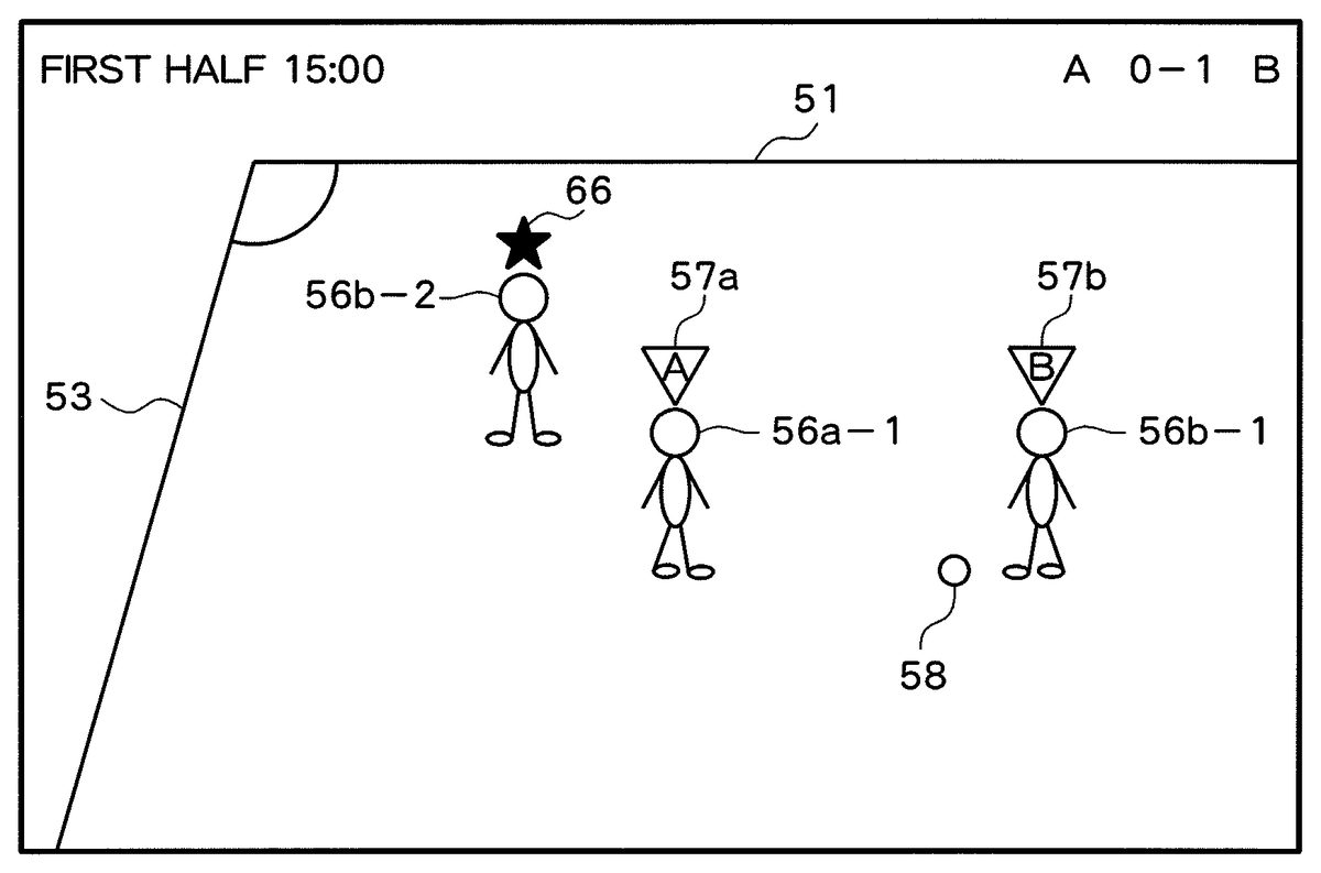
In the above, a game screen image such as is shown inFIG. 9is shown on the monitor18of the game machine B. On the game screen of the game machine B, the player object56b-2is shown, as shown inFIG. 9, with the display restricted player indicator mark66shown above the player object56b-2. Therefore, the user B can realize at a glance that it is highly likely that the user A does not realize the presence of the player object56b-2as the player object56b-2is not shown on the game screen of the game machine A, and therefore that use of the player object56b-2results in a situation advantageous to themselves. Note that the player object56b-2may be distinctively displayed by being shown in a manner different from others. For example, the player object56b-2may be shown blinking or in a predetermined color.
In the following, functions to be realized in the network game system1will be described. Note that in the network game system1, either the game machine A or B has a server function so that the contents of operation carried out in the game machines A and B is reflected on the game screen images shown in the respective game machines A and B. The following description is based on the assumption that the game machine A has the server function.
FIG. 10is a functional block diagram mainly showing functions according to the present invention among those realized in the network game system1. As shown, the network game system1comprises, in terms of functions, operation information obtaining units70a,70b, a game situation information update unit72a, storage units74a,74b, position condition determination units78a,78b, display control units80a,80b, and display units82a,82b. Among these units, the operation information obtaining unit70a, game situation information update unit72a, storage unit74a, position condition determination unit78a, display control unit80a, and display unit82aare included in the game machine A10a. These functions are realized in the game machine A10aby executing a game program read from the DVD-ROM25. The operation information obtaining unit70b, storage unit74b, position condition determination unit78b, display control unit80b, and display unit82bare included in the game machine B10b. These functions are realized in the game machine B10bby executing a game program read from the DVD-ROM25.
[1. Operation Information Obtaining Unit]
The operation information obtaining unit70ais realized mainly using the microprocessor14and input/output processing unit30of the game machine A10a. The operation information obtaining unit70aobtains operation information corresponding to the contents of an operation carried out by the user A, based on an operation signal input from the controller32. Similarly, the operation information obtaining unit70bis realized mainly using the microprocessor14and input/output processing unit30of the game machine B10b. The operation information obtaining unit70bobtains operation information corresponding to the contents of an operation carried out by the user B, based on an operation signal input from the controller32. Here, the operation information is information describing the contents of an operation carried out relative to, e.g., the respective operating members of the controller32. The operation information obtained by the operation information obtaining units70a,70bis supplied to the game situation information update unit72aof the game machine A10a.
[2. Storage Unit]
The storage unit74ais realized mainly using the main memory26and DVD-ROM25of the game machine A10a. The storage unit74bis realized mainly using the main memory26and DVD-ROM25of the game machine B10b. In the storage units74a,74b, data describing the shapes of various objects, such as, e.g., the player object56, ball object58, and so forth, (data describing the coordinates of the respective vertexes of the polygons forming the various objects) is stored. Further, for example, motion data describing change in the posture of the player object56taking various actions are stored in the storage units74a,74b. Still further, ability parameter values (a pass ability parameter, a first ability parameter, a second ability parameter, and so forth) of the respective player objects56placed in the game space50are also stored in the storage units74a,74b. Each ability parameter is expressed by any numeric value between 0 and 100, with an ability parameter value with a higher numeric value indicating higher ability.
[3. Game Situation Information Storage Unit]
The storage units74a,74brespectively include the game situation information storage units76aand76b. The game situation information storage units76a,76bstore game situation information describing the situation of a game. The game situation information includes information describing the states of, e.g., the respective player objects56, ball object58, and virtual camera placed in the game space50. Here, “information describing the state of the player object56” includes, e.g., information describing the position, posture, movement direction, moving speed of the player object56in the game space50, information describing the position kind of the player object56, information indicating whether or not the player object56holds the ball object58, and information indicating whether or not the player object56is the user's operation target. The “information describing the state of the ball object58” includes, e.g., information describing the position, movement direction, and moving speed of the ball object58in the game space50. The “information describing the state of the virtual camera” includes, e.g., information describing the position (a viewpoint position), posture (a viewing direction), and an angle of view, and so forth of the virtual camera in the game space50. The game situation information includes information describing a situation of a game, such as scores of the respective teams, a period of time elapsed after the match begins, and so forth.
In this embodiment, in the respective game situation information storage units76a,76b, player state tables describing the states of the player objects56of the respective teams are stored.FIG. 11shows a part of the player state table. As shown in the drawing, the player state table includes “player ID”, “position kind”, “position”, “orientation”, “ball holding flag”, and “operation target flag” fields. In the “player ID” field, a player ID for uniquely identifying each player object56placed in the game space50is stored. Note that a player object56having a player ID beginning with “A” belongs to the team A, and a player object56having a player ID beginning with “B” belongs to the team B. In the “position kind” field, the position kind of a player object56is stored. In the “position” field, the position coordinates of a representative point (e.g., a central point) of a player object56in the game space50are stored. In the “orientation” field, a unit vector indicating the reference direction60(e.g., the front direction or viewing direction) of a player object56is stored. In the “ball holding flag” field, information indicating whether or not a player object56holds the ball object58is stored. When the player object56does not hold the ball object58, the “ball holding flag” field is set to 0, and when the player object56holds the ball object58, the “ball holding flag” field is to 1. In the “operation target flag” field, information describing whether or not the player object56is the user's operation target is stored. When the player object56is not the user's operation target, the “operation target flag” field is set to 0. When the player object56is the user's operation target, the “operation target flag” field is set to 1.
Also, in the game situation information storage units76a,76b, display restriction tables which show display restriction states of the player objects56of the respective teams are stored.FIG. 12shows one example of the display restriction table. As shown in the drawing, the display restriction table includes a “player ID” field and a “display restriction flag” field. In the “display restriction flag” field, information describing whether or not display output of a player object56on the game screen is restricted is stored. When display output on a game screen is not restricted, the “display restriction flag” field is set to 0. When display output on a game screen is restricted, the “display restriction flag” field is set to 1. The display restriction table stored in the game situation information storage unit76ais updated based on the result of determination by the position condition determination unit78a. The display restriction table stored in the game situation information storage unit76bis updated based on the result of determination by the position condition determination unit78b. Details of the updates will be described later.
[4. Game Situation Information Update Unit]
The game situation information update unit72ais realized mainly using the microprocessor14of the game machine A10a. The game situation information update unit72aupdates the game situation information stored in the game situation information storage units76a,76b.
For example, the game situation information update unit72aupdates the information describing the state of the user A's operation target player object56, based on the operation information supplied from the operation information obtaining unit70a. Also, for example, when a dribble instruction operation, a pass instruction operation, a shoot instruction operation, or the like is carried out while the user A's operation target player object56holds the ball object58, the game situation information update unit72aupdates the information describing the state of the ball object58, based on the operation information supplied from the operation information obtaining unit70a.
Further, for example, the game situation information update unit72aupdates the information describing the state of the user B's operation target player object56, based on the operation information supplied from the operation information obtaining unit70b. Also, for example, when a dribble instruction operation, a pass instruction operation, a shoot instruction operation, and so forth is carried out while the user B's operation target player object56holds the ball object58, the game situation information update unit72aupdates the information describing the state of the ball object58, based on the operation information supplied from the operation information obtaining unit70b.
Also, for example, the game situation information update unit72aupdates the information describing the states of the player objects56other than the users A and B′ operation target player objects56, according to a predetermined algorithm.
When game situation information stored in the game situation information storage unit76ais updated, the game situation information update unit72areads the updated game situation information, and sends the read updated game situation information as game situation update information to the game machine B10b. Alternatively, information describing the contents of update made after the last transmission of the game situation update information may be sent as game situation update information.
[5. Position Condition Determination Unit]
The position condition determination unit78ais realized mainly using the microprocessor14of the game machine A10a. The position condition determination unit78adetermines whether or not the position of a player object56(a second game character) included in the display target area, among the player objects56belonging to the team B, satisfies the position condition based on the position and orientation of the player object56(a first game character) belonging to the team A. Similarly, the position condition determination unit78bis realized mainly using the microprocessor14of the game machine B10b. The position condition determination unit78bdetermines whether or not the position of a player object56(a second game character) included in the display target area, among the player objects56belonging to the team A, satisfies the position condition based on the position and orientation of the player object56(a first game character) belonging to the team B.
In this embodiment, the position condition determination units78a,78bdetermine whether or not the respective player objects56belonging to the respective teams A and B satisfy the above described conditions Ito6. This determination is made based on the game situation information (a player state table (FIG. 11) and so forth) stored in the game situation information storage units76a,76b, and the ability parameters of the respective player objects56, stored in the storage units74a,74b. The position condition determination units78a,78bupdate the display restriction table (FIG. 12), based on the result of the determination. More specifically, when the player object56does not satisfy any of the above described conditions 1 to 6, the display restriction flag (FIG. 12) of the player object56is updated to 0, and when the player object56satisfies the above described conditions 1 to 6, the display restriction flag (FIG. 12) of the player object56is updated to 1.
[6. Display Control Unit and Display Unit]
The Display control unit80ais realized mainly using the microprocessor14and image processing unit16of the game machine A10a. The display unit82ais realized mainly using the monitor18of the game machine A10a. The display control unit80aproduces a game screen image showing a picture viewed from the virtual camera, where the “game space50where the respective player objects56and ball object58are placed based on the game situation information stored in the game situation information storage unit76a”, and displays the game screen image on the display unit82a.
In the above, the display control unit80a(display restriction means) restricts display output of the player object56of the team B on the game screen of the display unit82a, based on the display restriction table (FIG. 12) stored in the game situation information storage unit76a. More specifically, with the display restriction flag of the player object56of the team B set to 1, the display control unit80adoes not show the player object56on the game screen even when the player object56is included within the display target area of the game space50. Note that in the above, only the shadow of the player object56may be shown.
Also, with the display restriction flag of the player object56of the team A set to 1, the display control unit80a(distinctive display means) distinctively shows the player object56. For example, the display control unit80amay show the player object56in a manner different from that of the other player objects56. More specifically, the display control unit80amay display the player object56blinking or in a predetermined color. Also, for example, the display control unit80ashows a predetermined image at a position based on the display position of the player object56on the game screen. In this embodiment, with the display restriction flag of the player object56of the team A set to 1, the display control unit80ashows the display restricted player indicator mark66at a predetermined position above the player object56.
The display control unit80bis realized mainly using the microprocessor14and image processing unit16of the game machine B10b. The display unit82bis realized mainly using the monitor18of the game machine B10b. The display control unit80bproduces a game screen image showing a picture obtained by viewing, from the virtual camera, the “game space50where the respective player objects56and ball object58are placed based on the game situation information stored in the game situation information storage unit76b”, and shows the produced game screen image on the display unit82b.
In the above, similar to the display control unit80a, the display control unit80b(display restriction means) restricts display output of the player object56of the team A on the game screen of the display unit82b, based on the display restriction table (FIG. 12) stored in the game situation information storage unit76b. More specifically, with the display restriction flag of the player object56of the team A set to 1, the display control unit80bdoes not show the player object56on the game screen even when the player object56is included within the display target area of the game space50.
Also, similar to the display control unit80a, with the display restriction flag of the player object56of the team B set to 1, the display control unit80b(distinctive display means) distinctively shows the player object56. In this embodiment, with the display restriction flag of the player object56of the team B set to 1, the display control unit80bshows the display restricted player indicator mark66at a predetermined position above the player object56.
It should be noted that the display control units80a,80bmay control the permeability (a degree of semi-transparency) of the player object56to thereby restrict display output of the player object56on the game screen. More specifically, the display control units80a,80bmay control the alpha values of the respective vertexes of the polygons forming the player object56, to thereby restrict display output of the player object56on the game screen. For example, any integer value between 0 and 255 is usable for setting as an alpha value. In the case where a larger alpha value results in smaller permeability, the alpha values of the respective vertexes of the player object56with the display restriction flag set to 0 may be set to 255, and those with the display restriction flag set to 1 may be set to, e.g.,32, or the like. Note that a case in which a larger alpha value results in smaller permeability refers to a case in which a “player object56is completely transparent” with respect to the alpha value 0, and a “player object56is completely opaque” with respect to the alpha value 255.
Also, the display control units80a,80bcontrol the display size of the player object56, to thereby restrict display output of the player object56on the game screen. More specifically, with the player object56having the display restriction flag set to 1, the player object56may be shown smaller in size than normal.
In the following, processes to be carried out in the game machine A10aand the game machine B10bwill be described.FIG. 13is a flowchart of a process according to the present invention among those to be carried out in the game machine A10aand the game machine B10bevery predetermined period of time (e.g., 1/60thof a second). A game program for causing the microprocessor14to carry out this process is read from the DVD-ROM2in each of the game machine A10aand the game machine B10b, and carried out by the microprocessor14, whereby the above described respective functional blocks (FIG. 10) are realized.
As shown inFIG. 13, the process from S102to S105is initially carried out in the game machine A10a(S101: Y), and the process from S106to S109is initially carried out in the game machine B10b(S101: N).
In the game machine A10a, operation information describing the contents of an operation carried out by the user A is obtained based on an operation signal input from the controller32(S102). In addition, operation information sent from the game machine B10bis obtained (S103). The operation information is information describing the contents of an operation carried out by the user B in the game machine B10b(see S106and S107). Then, the game situation information stored in the game situation information storage unit76ais updated based on the operation information obtained at5102and5103(S104). Thereafter, the game situation information updated in the process at S104is read from the game situation information storage unit76a, and sent as game situation update information to the game machine B10b(S105).
Meanwhile, in the game machine B10b, operation information describing the contents of an operation carried out by the user B is obtained based on an operation signal input from the controller32(S106), and the operation information is sent to the game machine A10a(S107). Further, in the game machine B10b, whether or not the game situation update information from the game machine A10ais received is determined (S108). In the case where it is determined that the game situation update information sent from the game machine A10ais received (S108: Y), the game situation information stored in the game situation information storage unit76ais updated based on the game situation update information (S109).
After the process from S102to S105or that from S106to S109, a display restriction flag setting process is carried out (S110).
FIGS. 14 and 15are flowcharts of the display restriction flag setting process. In the display restriction flag setting process, initially, the display restriction flags (FIG. 12) for the respective player objects56of the teams A and B are initialized to 0 (S201). Then, whether or not the team A holds the ball object58is determined (S202). This determination is made based on the game situation information.
In the case where it is determined that the team A holds the ball object58(S202: Y), a process to update the display restriction flag for the player object56of the team A (S203to S211) is carried out. That is, while referring to the player state table (FIG. 11), whether or not the position kind of the user B's operation target player object56is a defender is determined (S203).
In the case where it is determined that the position kind of the user B's operation target player object56is not a defender (S203: N), this process is terminated. Meanwhile, in the case where the position kind of the user B's operation target player object56is a defender (S203: Y), the player objects56of the team A are sorted according to the ascending order of the player IDs', and the initial player object56is set as a focused player object (S204).
With the focused player object set, while referring to the player state table (FIG. 11), whether or not the position kind of the focused player object is a forward is determined (S205).
In the case where it is determined that the position kind of the focused player object is not a forward (S205: N), the process at S210is carried out, without updating the display restriction flag (FIG. 12) for the focused player object to 1. Meanwhile, in the case where the position kind of the focused player object is a forward (S205: Y), while referring to the player state table (FIG. 11), whether or not the position of the focused player object is located within the goal front area59of the team B is determined (S206).
In the case where it is determined that the position of the focused player object is not located within the goal front area59of the team B (S206: N), the process at S210is carried out without updating the display restriction flag (FIG. 12) for the focused player object to 1. Meanwhile, in the case where the position of the focused player object is located within the goal front area59of the team B (S206: Y), while referring to the player state table (FIG. 11), whether or not the position of the focused player object is located within the dead angle area64of the user B's operation target player object56is determined (S207).
More specifically, whether or not the angle formed by the rear direction62of the user B's operation target player object56and the direction extending from the user B's operation target player object56to the focused player object is equal to or smaller than a predetermined reference angle (θ) is determined. Further, the distance between the user B's operation target player object56and the focused player object is equal to or shorter than a predetermined reference distance (R) is determined. In the case where the above described angle is equal to or smaller than the reference angle (θ) and the above described distance is equal to or shorter than the reference distance (R), it is concluded that the position of the focused player object is located within the dead angle area64of the user B's operation target player object56.
In the case where it is determined that the position of the focused player object is not located within the dead angle area64of the user B's operation target player object56(S207: N), the process at S210is carried out without updating the display restriction flag (FIG. 12) for the focused player object to 1. Meanwhile, in the case where the position of the focused player object is located within the dead angle area64of the user B's operation target player object56(S207: Y), whether or not the first ability parameter value of the focused player object is larger than the second ability parameter value of the user B's operation target player object56is determined (S208).
In the case where it is determined that the first ability parameter value of the focused player object is equal to or smaller than the second ability parameter value of the user B's operation target player object56(S208: N), the process at5210is carried out without updating the display restriction flag (FIG. 12) for the focused player object to 1. Meanwhile, in the case where the first ability parameter value of the focused player object is larger than the second ability parameter value of the user B's operation target player object56(S208: Y), the display restriction flag (FIG. 12) for the focused player object is updated to 1 (S209).
After the process at S205to S209, whether or not there exists another player object56after the focused player object is determined (S210). In the case where it is determined no player object56exists after the focused player object (S210: N), this process is terminated. Meanwhile, in the case where there another player object56exists after the focused player object (S210: Y), the player object56is set as a focused player object (S211), and the process at S205to S209is carried out. As described above, in the process for updating the display restriction flag for the player object56of the team A, the player objects56of the team A are sequentially set as a focused player object in the ascending order of the player IDs', and the process from S205to S209is carried out.
In the case where it is determined at S202that the team A does not hold the ball object58(S202: N), whether or not the team B holds the ball object58is determined (S212). This determination is made based on the game situation information.
In the case where it is determined that the team B does not hold the ball object58(S212: N), this process is terminated. Meanwhile, in the case where the team B holds the ball object58(S212: Y), a process (S213to S221) for updating the display restriction flag for the player object56of the team B is carried out. That is, while referring to the player state table (FIG. 11), whether or not the position kind of the user A's operation target player object56is a defender is determined (S213).
In the case where it is determined that the position kind of the user A's operation target player object56is not a defender (S213: N), this process is terminated. Meanwhile, in the case where the position kind of the user A's operation target player object56is a defender (S213: Y), the player objects56of the team B are sorted according to the ascending order of the player IDs', and the initial player object56is set as a focused player object (S214).
With the focused player object set, while referring to the player state table (FIG. 11), whether or not the position kind of the focused player object is a forward is determined (S215).
In the case where it is determined that the position kind of the focused player object is not a forward (S215: N), the process at S220is carried out without updating the display restriction flag (FIG. 12) for the focused player object to 1. Meanwhile, in the case where the position kind of the focused player object is a forward (S215: Y), while referring to the player state table (FIG. 11), whether or not the position of the focused player object is located within the goal front area59of the team A is determined (S216).
In the case where it is determined that the position of the focused player object is not located within the goal front area59of the team A (S216: N), the process at S220is carried out without updating the display restriction flag (FIG. 12) for the focused player object to 1. Meanwhile, in the case where the position of the focused player object is located within the goal front area59of the team A (S216: Y), while referring to the player state table (FIG. 11), whether or not the position of the focused player object is located within the dead angle area64of the user A's operation target player object56is determined (S217).
More specifically, the angle formed by the rear direction62of the user A's operation target player object56and the direction extending from the user A's operation target player object56to the focused player object is equal to or smaller than a predetermined reference angle (θ) is determined. Further, whether or not the distance between the user A's operation target player object56and the focused player object is equal to or shorter than a predetermined reference distance (R) is determined. In the case where it is determined that the above described angle is equal to or smaller than the reference angle (θ) and the above described distance is equal to or shorter than the reference distance (R), it is concluded that the position of the focused player object is included within the dead angle area64of the user A's operation target player object56.
In the case where it is determined that the position of the focused player object is not located within the dead angle area64of the user A's operation target player object56(S217: N), the process at S220is carried out without updating the display restriction flag (FIG. 12) for the focused player object to 1. Meanwhile, in the case where the position of the focused player object is located within the dead angle area64of the user A's operation target player object56(S217: Y), whether or not the first ability parameter value of the focused player object is larger than the second ability parameter value of the user A's operation target player object56is determined (S218).
In the case where it is determined that the first ability parameter value of the focused player object is equal to or smaller than the second ability parameter value of the user A's operation target player object56(S218: N), the process at5220is carried out without updating the display restriction flag (FIG. 12) for the focused player object to 1. Meanwhile, in the case where the first ability parameter value of the focused player object is larger than the second ability parameter value of the user A's operation target player object56(S218: Y), the display restriction flag (FIG. 12) for the focused player object is updated to 1 (S219).
After the processes from 5215 to S219, whether or not another player object56exists after the focused player object is determined (S220). In the case where it is determined that no player object56exists after the focused player object (S220: N), this process is terminated. Meanwhile, in the case where another player object56exists after the focused player object (S220: Y), the player object56is set as a focused player object (S221), and the process from S215to S220is carried out. As described above, in the process for updating the display restriction flag for the player object56of the team B, the player objects56of the team B are sequentially set as a focused player object in the ascending order of the player IDs', and the process from S215to S220is carried out.
It should be noted that in the process at S207and S217, the values of the reference angle (θ) and reference distance (R) may be changed based on at least one of the first ability parameter value of the focused player object and the second ability parameter value of the user A or B's operation target player object56. For example, as the first ability parameter value of the focused player object becomes larger, the value of the reference angle (θ) may also become larger. Also, for example, as the second ability parameter value of the user A or B's operation target player object56becomes larger, the value of the reference angle (θ) may become smaller. Also, for example, as the value obtained by subtracting the second ability parameter value of the user A or B's operation target player object56from the first ability parameter value of the focused player object becomes larger, the value of the reference angle (θ) may become larger.
After the process at S110(the process from S201to S221), a game screen image is produced (S111).
For example, in the game machine A10a, an image showing a picture obtained by viewing, from the virtual camera, the “game space50where the respective player objects56and ball object58are placed, based on the game situation information stored in the game situation information storage unit76a”, is rendered into the VRAM. In the above, the display restriction table (FIG. 12) stored in the game situation information storage unit76ais refereed to. In the case where any player object56having the display restriction flag set to 1 exists among the player objects56of the team B, rendering of the image of that player object56is restricted. Then, the player state table (FIG. 11) stored in the game situation information storage unit76ais referred to. Then, the operation target player indicator mark57aor57bis overwritten into predetermined positions above the operation target player objects56of the users A and B in the image rendered in the VRAM. Also, the display restriction table (FIG. 12) stored in the game situation information storage unit76ais referred to, and in the case where a player object56having the display restriction flag set to 1 exists among the player objects56of the team A, a display restricted player indicator mark66is overwritten into a predetermined position above the player object56in the image rendered in the VRAM. Further, a score image and an elapsed time image are overwritten into the image rendered in the VRAM. As described above, a game screen image (FIG. 8) is formed in the VRAM. The game screen image formed in the VRAM is displayed on the display unit82afor output at a predetermined time.
Also, for example, in the game machine B10b, an image showing a picture obtained by viewing, from the virtual camera, the “game space50where the respective player objects56and ball object58are placed, based on the game situation information stored in the game situation information storage unit76b”, is rendered into the VRAM. In the above, the display restriction table (FIG. 12) stored in the game situation information storage unit76bis referred to. In the case where any player object56having the display restriction flag set to 1 exists among the player objects56of the team A, rendering of the image of that player object56is restricted. Then, the player state table (FIG. 11) stored in the game situation information storage unit76bis referred to. The operation target player indicator marks57aand57bare overwritten into the respective predetermined positions above the users A and B′ operation target player objects56in the image rendered in the VRAM. Also, the display restriction table (FIG. 12) stored in the game situation information storage unit76bis referred to, and in the case where a player object56having the display restriction flag set to 1 exists among the player objects56of the team A, the display restricted player indicator mark66is overwritten into a predetermined position above the player object56in the image rendered in the VRAM. Further, a score image and an elapsed time image are overwritten into the image rendered in the VRAM. In this manner, a game screen image (FIG. 9) is formed in the VRAM. The game screen image formed in the VRAM is displayed on the display unit82bfor output at a predetermined time.
According to the above described network game system1, a picture in which, when a forward player object56of one team moves so as to disappear from the view of a defender player object56of the other team, the defender player object56loses sight of the forward player object56can be preferably produced. For example, assume a case, as shown inFIG. 7, in which the user A's operation target player object56a-1, the user B's operation target player object56b-1, and the player object56b-2of the team B are placed in the game space50. In this case, when the player object56b-2satisfies all of the above described conditions 1 to 6, the player object56b-2is not shown on the game screen of the game machine A10a, such as is shown inFIG. 8. That is, the user A cannot realize the presence of the player object56b-2. Thus, when the player object56b-1passes the ball object58to the player object56b-2in response to, e.g., a pass instruction operation made by the user B, response (defense) to the player object56b-2is delayed. That is, a picture in which the user A's operation target player object56a-1loses sight of the player object56b-2is preferably produced.
Also, in the network game system1, the user can realize at a glance that a forward player object56of their own team moves so as to disappear from the view of a defender player object56of the opponent team. For example, assume a case, as shown inFIG. 7, in which the user A's operation target player object56a-1, the user B's operation target player object56b-1, and a player object56b-2of the team B are placed in the game space50. In this case, for example, when the player objet56b-2satisfies all of the above described conditions 1 to 6, the display restricted player indicator mark66is shown above the player object56b-2shown on the game screen of the game machine B10b, as shown inFIG. 9, whereby the player object56b-2is distinctively displayed. Therefore, the user B can understand at a glance that it is likely that the user A does not realize the presence of the player object56b-2as the player object56b-2is not shown on the game screen of the game machine A10a, and therefore that use of the player object56b-2may result in a situation advantageous to themselves.
It should be noted that the present invention is not limited to the above-described embodiment.
For example, the network game system1may include a game server in addition to the game machine A10aand the game machine B10b. In this case, the contents of operations carried out by the users A and B may be reflected via the game server on the game screen images shown in the game machine A10aand the game machine B10b.
Also, for example, the network game system1may include three or more game machines10. Also, for example, one team may be operated by a plurality of users.
Also, for example, in addition to the above described conditions 1 to 6, a condition stating that “a moving speed within the dead angle area64of the opponent user's operation target player object56is equal to or faster than a predetermined speed” may be added. Also, for example, the dead angle area64of the player object56may be defined as a fan-like area in which an angle formed by the “direction opposite to the direction from the player object56to the ball object58” and a direction extending from the position of the player object56is equal to or smaller than a predetermined reference angle (θ), and the distance (a distance on the XZ plane system) from the player object56is within a predetermined reference distance (R).
Also, for example, in addition to the above described conditions 1 to 6, a condition stating that “the state of the player object56is changed from a state of not holding the ball object58to a state of holding the ball object58” may be added. In other words, a condition stating that the “player object56receives the ball object58passed from a teammate player object56” may be added. In the state shown inFIG. 7, for example, at a time when the player object56b-2shifts to the state of holding the ball object58after having received the ball object58from the player object56b-1, display restriction of the player object56b-2on the game screen of the game machine A10amay be effected.
Also, for example, in the display restriction flag setting process shown inFIGS. 14 and 15, the display restriction flag of the player object56satisfying the above described conditions 1 to 6, which is then set to 1, is changed to 0 at a time when the player object56no longer satisfies the above described conditions 1 to 6, whereby display restriction on the player object56is released. Alternatively, the display restriction flag of the player object56satisfying the above described conditions 1 to 6, which is then set to 1, may be changed to 0 after elapse of a predetermined period of time after a time when the above described conditions 1 to 6 are satisfied (that is, the display restriction begins), whereby display restriction on the player object56is released.
Also, for example, a game carried out in the game machine10is not limited to a soccer game, and may be, e.g., any sport game (a game, such as basketball, ice hockey, or the like, carried out using a moving body such as a ball, a puck, or the like) other than a soccer game. Also, a game carried out in the game machine10may be any game (an action game or the like) other than a sport game. The present invention can be applied to, e.g., a game system other than a so-called network game system. For example, the present invention can be applied to a game machine and so forth which includes a controller32and a monitor18for a user A and a controller32and monitor18for a user B. The present invention can be applied to a game machine for producing a game which requires preferable production of a picture in which a first game character loses sight of a second game character having moved so as to disappear from the view of the first game character.
Claims
- A game system including a first game machine and a second game machine, for displaying, on a first display unit corresponding to the first game machine, a picture of a display target area in a common game space where one or more first game characters corresponding to a team of the first game machine and one or more second game characters corresponding to a team of the second game machine are placed, the game system, comprising: position condition determination means for determining whether or not a position of a second game character included in the display target area among the one or more second game characters is within a dead angle area of a first game character, wherein the dead angle area of the first game character is set based on a position and orientation of the first game character;and display restriction means for restricting display of the second game character included in the display target area among the one or more second game characters on the first display unit, in a case where the second game character moves into the dead angle area of the first game character, based on a result of determination by the position condition determination means, wherein the position condition determination means determines whether the second game character is within a predetermined area in front of a goal object, and wherein the display restriction means restricts display of the second game character only when the second character is within the predetermined area in front of the goal object.
- The game system according to claim 1 , wherein the display restriction means controls a degree of semi-transparency of the second game character included in the display target area among the one or more second game characters, based on the result of determination by the position condition determination means.
- The game system according to claim 2 , wherein at least a part of the display target area is displayed on a second display unit corresponding to the second game machine, the display restriction means, in the case where the position of the second game character included in the display target area among the one or more second game characters is within the dead angle area of the first game character, restricts display of the second game character on the first display unit, and the game system includes distinctive display means, in the case where the position of the second game character included in the display target area among the one or more second game characters is within the dead angle area of the first game character, and the second game character is displayed on the second display unit, for distinctively displaying the second game character on the second display unit.
- The game system according to claim 1 , wherein the display restriction means controls a display size of the second game character included in the display target area among the one or more second game characters, displayed on the first display unit, based on the result of determination by the position condition determination means.
- The game system according to claim 4 , wherein at least a part of the display target area is displayed on a second display unit corresponding to the second game machine, the display restriction means, in the case where the position of the second game character included in the display target area among the one or more second game characters is within the dead angle area of the first game character, restricts display of the second game character on the first display unit, and the game system includes distinctive display means, in the case where the position of the second game character included in the display target area among the one or more second game characters is within the dead angle area of the first game character, and the second game character is displayed on the second display unit, for distinctively displaying the second game character on the second display unit.
- The game system according to claim 1 , wherein the position condition determination means includes means for determining whether or not an angle formed by a reference direction of the first game character and a direction from the first game character to the second game character is included in a predetermined angle range.
- The game system according to claim 6 , wherein at least a part of the display target area is displayed on a second display unit corresponding to the second game machine, the display restriction means, in the case where the position of the second game character included in the display target area among the one or more second game characters is within the dead angle area of the first game character, restricts display of the second game character on the first display unit, and the game system includes distinctive display means, in the case where the position of the second game character included in the display target area among the one or more second game characters is within the dead angle area of the first game character, and the second game character is displayed on the second display unit, for distinctively displaying the second game character on the second display unit.
- The game system according to claim 6 , wherein the position condition determination means includes means for controlling an angle range, based on a value assigned to at least one of the first game character and the second game character.
- The game system according to claim 8 , wherein at least a part of the display target area is displayed on a second display unit corresponding to the second game machine, the display restriction means, in the case where the position of the second game character included in the display target area among the one or more second game characters is within the dead angle area of the first game character, restricts display of the second game character on the first display unit, and the game system includes distinctive display means, in the case where the position of the second game character included in the display target area among the one or more second game characters is within the dead angle area of the first game character, and the second game character is displayed on the second display unit, for distinctively displaying the second game character on the second display unit.
- The game system according to claim 1 , wherein at least a part of the display target area is displayed on a second display unit corresponding to the second game machine, the display restriction means, in the case where the position of the second game character included in the display target area among the one or more second game characters is within the dead angle area of the first game character, restricts display of the second game character on the first display unit, and the game system includes distinctive display means, in the case where the position of the second game character included in the display target area among the one or more second game characters is within the dead angle area of the first game character, and the second game character is displayed on the second display unit, for distinctively displaying the second game character on the second display unit.
- A game machine included in a game system, comprising: display means for displaying a picture of a display target area in a common game space where one or more first game characters corresponding to a team of the game machine and one or more second game characters corresponding to a team of another game machine are placed, and display restriction means for restricting display of a second game character included in the display target area among the one or more second game characters, on the display means, in a case where the second game character moves into a dead angle area of a first game character, based on a result of determination as to whether or not a position of the second game character included in the display target area, among the one or more second game characters, is within the dead angle area of the first game character, wherein the dead angle area of the first game character is set based on a position and orientation of the first game character, wherein the display restriction means restricts the display of the second game character only when the second character is within a predetermined area in front of a goal object.
- A control method for controlling a game machine included in a game system, the control method comprising: displaying a picture of a display target area in a common game space where one or more first game characters corresponding to a team of the game machine and one or more second game characters corresponding to a team of another game machine are placed;determining whether a second game character is within a predetermined area in front of a goal object;and restricting, by one or more processors, display of a second game character included in the display target area among the one or more second game characters, in a case where the second game character moves into a dead angle area of a first game character, based on a result of determination as to whether or not a position of the second game character included in the display target area, among the one or more second game characters, is within the dead angle area of the first game character, wherein the dead angle area of the first game character is set based on a position and orientation of the first game character, wherein the display of the second game character is restricted only when the second character is within the predetermined area in front of the goal object.
- A non-transitory computer readable information storage medium recording a program for causing a computer to function as a game machine in a game system and performing a method comprising: displaying a picture of a display target area in a common game space where one or more first game characters corresponding to a team of the game machine and one or more second game characters corresponding to a team of another game machine are placed;determining whether a second game character, among the second game characters, is within a predetermined area in front of a goal object;and restricting display of a second game character included in the display target area among the one or more second game characters, in a case where the second game character moves into a dead angle area of a first game character, based on a result of determination as to whether or not a position of the second game character included in the display target area, among the one or more second game characters, is within the dead angle area of the first game character, wherein the dead angle area of the first game character is set based on a position and orientation of the first game character, wherein the display of the second game character is restricted only when the second character is within the predetermined area in front of the goal object.
- A game system including a first game machine and a second game machine, for displaying, on a first display unit corresponding to the first game machine, a picture of a display target area in a common game space where one or more first game characters corresponding to a team of the first game machine and one or more second game characters corresponding to a team of the second game machine are placed, the game system, comprising: one or more processors configured to: determine whether or not a position of a second game character included in the display target area among the one or more second game characters is within a dead angle area of a first game character, wherein the dead angle area of the first game character is set based on a position and orientation of the first game character;and restrict display of the second game character included in the display target area among the one or more second game characters on the first display unit, in a case where the second game character moves into the dead angle area of the first game character wherein the display of the second game character is restricted only when the second character is within a predetermined area in front of a goal object.
- A game machine included in a game system, comprising: one or more processors configured to: display, on a display unit, a picture of a display target area in a common game space where one or more first game characters corresponding to a team of the game machine and one or more second game characters corresponding to a team of another game machine are placed, and restrict display of a second game character included in the display target area among the one or more second game characters on the display unit, in a case where the second game character moves into a dead angle area of a first game character, based on a result of determination as to whether or not a position of the second game character included in the display target area, among the one or more second game characters, is within the dead angle area of the first game character, wherein the dead angle area of the first game character is set based on a position and orientation of the first game character, wherein the display of the second game character is restricted only when the second character is within a predetermined area in front of a goal object.
Disclaimer: Data collected from the USPTO and may be malformed, incomplete, and/or otherwise inaccurate.