U.S. Pat. No. 8,672,758
STEERING COLUMN GAME CONTROLLER
AssigneeGuillemot Corporation
Issue DateMay 12, 2011
Illustrative Figure
Abstract
The invention relates to a video game controller (1) having a rotatable actuator (2) with respect to a frame (3), so as to simulate at least one simulated vehicle steering column rotation control. According to the invention, said actuator (2) is translatably mounted with respect to said fixed frame (3), on a predetermined movement range, using an assembly of two sliding parts (4, 5) with one or both sliding with respect to the other, one of said sliding parts (4, 5) being rigidly connected to said actuator (2) and the other to said fixed frame (3), a first of said sliding parts (4) comprising at least one slot (F), accessible by an opening (41) in which one penetrating portion (51) of the second of said sliding parts (5) moves along one separate axis of the rotation movement axis of said actuator (2), the translation movement of said actuator (2) being generated by electromagnetic means controlled by an electrical signal, the first of said sliding parts comprising at least one winding and the second of said sliding parts comprising a magnet.
Description
DETAILED DESCRIPTION General Principle Steering column video game controllers comprise an actuator which generally consists of handlebars or a steering wheel enabling the user to vary the trajectory of the simulated vehicle. Obviously, other types of actuators may be envisaged, for example to simulate the control of a ship, aircraft, spaceship, etc. In a known manner, the rotation of the steering column may be boosted by a torque and vibration effect system making it possible to create torque effects and/or vibration effects around the axis of rotation of the video game controller. The principle of the invention consists of creating new force feedback axes on the game controllers with at least one translation of the steering column thus offering new force feedback effects and more realistic simulations. The first and second force feedback effects systems each provide varied effects (inertia, blockage, shock absorption, impact, vibration sensations, etc.). In the particular embodiment described hereinafter, this translation is carried out along the axis of the column or along a close axis via an assembly of two sliding parts with one sliding with respect to the other and an electromagnetic device thus simulating suspension, acceleration and/or deceleration effects, in particular. Detailed Description of a Particular Embodiment In the embodiment described hereinafter, the actuator is a steering wheel (such as a touring vehicle steering wheel) which is detachable from a frame. FIG. 1is a perspective view of an example of a video game controller according to the invention. This controller1comprises an actuator2, in the form of a rotatably movable steering wheel with respect to a frame3around an axis A of rotation, the frame3being suitable for being mounted on a supporting member (not represented), said supporting member being optionally fixed. This frame3comprises an upper shell31assembled in a removable manner with a lower shell32and with a ...
DETAILED DESCRIPTION
General Principle
Steering column video game controllers comprise an actuator which generally consists of handlebars or a steering wheel enabling the user to vary the trajectory of the simulated vehicle.
Obviously, other types of actuators may be envisaged, for example to simulate the control of a ship, aircraft, spaceship, etc.
In a known manner, the rotation of the steering column may be boosted by a torque and vibration effect system making it possible to create torque effects and/or vibration effects around the axis of rotation of the video game controller.
The principle of the invention consists of creating new force feedback axes on the game controllers with at least one translation of the steering column thus offering new force feedback effects and more realistic simulations.
The first and second force feedback effects systems each provide varied effects (inertia, blockage, shock absorption, impact, vibration sensations, etc.).
In the particular embodiment described hereinafter, this translation is carried out along the axis of the column or along a close axis via an assembly of two sliding parts with one sliding with respect to the other and an electromagnetic device thus simulating suspension, acceleration and/or deceleration effects, in particular.
Detailed Description of a Particular Embodiment
In the embodiment described hereinafter, the actuator is a steering wheel (such as a touring vehicle steering wheel) which is detachable from a frame.
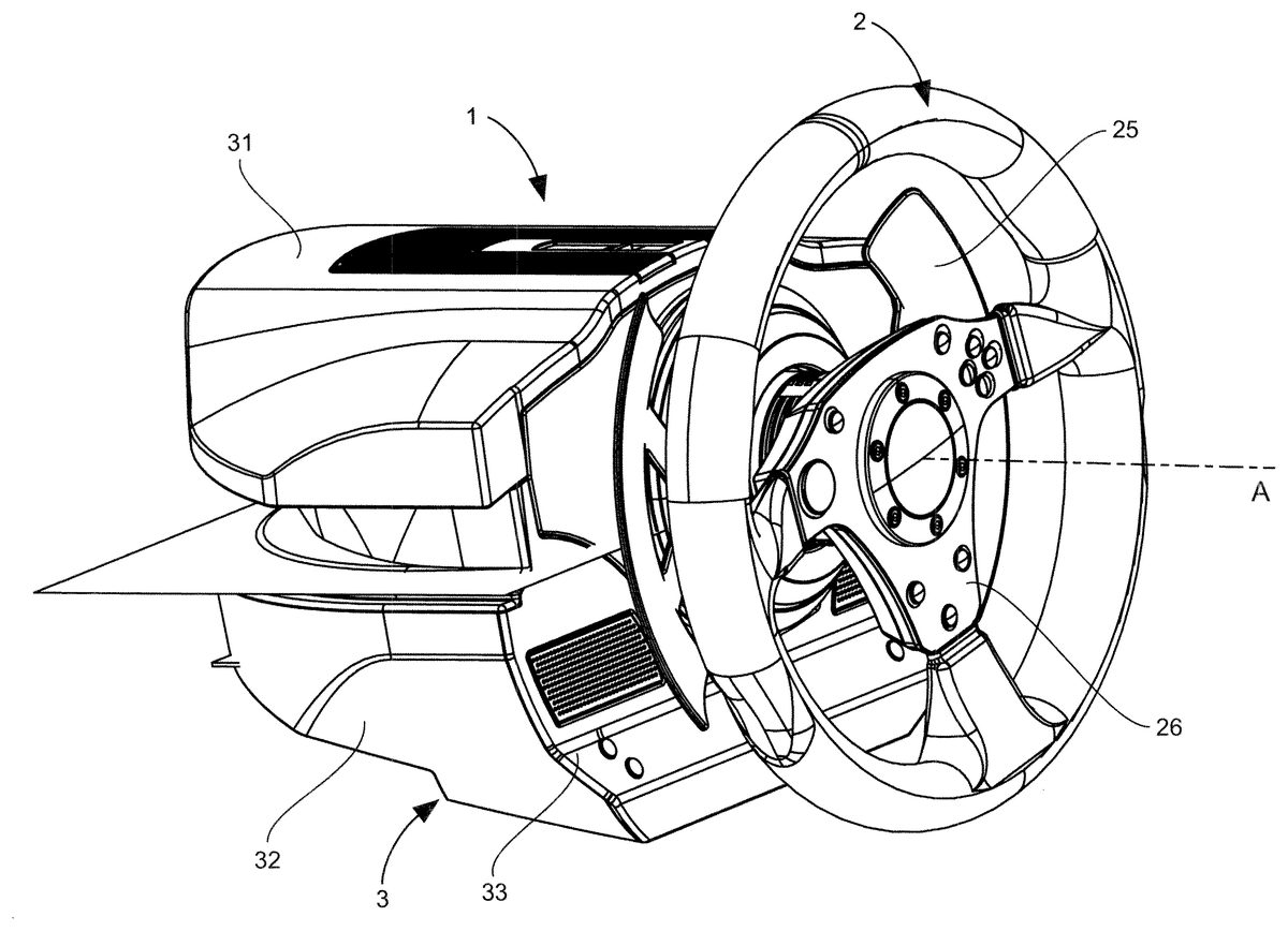
FIG. 1is a perspective view of an example of a video game controller according to the invention. This controller1comprises an actuator2, in the form of a rotatably movable steering wheel with respect to a frame3around an axis A of rotation, the frame3being suitable for being mounted on a supporting member (not represented), said supporting member being optionally fixed. This frame3comprises an upper shell31assembled in a removable manner with a lower shell32and with a front face33. The lower shell32of the frame3provides the optionally reversible link or attachment of the controller1with a supporting member such as a table or a worktop or a cockpit. The game controller1may be associated with pedals and, if the gears are not changed on the steering wheel, with a separate gear shift box from the steering wheel.
FIG. 1particularly shows the control knobs26and gear shift paddles25arranged on the actuator2. The controller1comprises an attachment system which allows the actuator2to be fixed and locked in a reversible manner on the frame3in order to enable the transmission of the rotation movement from the actuator2to the steering column which, in this embodiment, is the shaft31(seen inFIGS. 2 to 5). Numerous reversible attachment means may naturally be used, without leaving the scope of the invention.
In one simplified embodiment, it is also possible to use mere force-fitting of the steering wheel in the supporting member thereof.
FIGS. 2 and 3illustrate, via a perspective and side view respectively, the inside of the controller1once the upper shell31and the lower shell32have been removed. This figure shows the frame3comprising the front face33connected in a fixed manner to a plate34(FIG. 6), the shaft31(forming the steering column of the controller1) to which the actuator2is connected. The shaft31consists of a single part but it could consist of a plurality of parts attached to each other. The shaft31(or steering column31) is rigidly connected to the actuator2, and thus moves in rotation around the axis A similarly to the actuator2.
The rotation of the steering column31is boosted by a first system, referred to as a torque and vibration effect system by means, for example, of a rotary electric motor410acting on the steering column31via a gear and/or toothed belt system. In this case, a large diameter gear42(for precision) is attached coaxially to the steering column31. This gear42mechanically receives (via a gear and/or wheel mechanism and toothed belts) the forces applied by the electric motor410actuated according to torque effects or vibration effect(s) implemented by the video game. The gear42, and thus the steering column31and the actuator2, pivots or stops the rotation thereof around the axis A under the action of the electric motor410. For example, it can return the actuator2to the neutral position, or block the rotation of the steering column31, cause the rotation of the steering column31, cause jerks in the rotation of the steering column31, etc.
According to the invention, the steering column31, and thus the steering wheel2, is boosted in translation by a second system, referred to as the force feedback system.
For this purpose, the steering wheel2of the video game controller1is translatably mounted with respect to the fixed frame3along an axis of rotation A thereof or along an axis close to (and thus separate from) said axis A, over a predetermined movement range, using an assembly of two sliding parts, with one sliding with respect to the other. The translation movement of the steering wheel2is controlled by an electromagnetic device, which will be described in more detail hereinafter.
More specifically, the electromagnetic device controls the translation movement of a movable guiding body4with respect to the frame3and whereon the steering column31and the steering wheel2are rigidly connected. This guiding body4slides with respect to a guiding plate5which is rigidly connected to the fixed frame3.
The steering column is not horizontal but inclined with respect to the horizontal to enable the player to experience the force feedback effects in four directions (up, down, forward, reverse) via only one electromagnetic device, a guiding body4and a guiding plate5.
The steering column has an angle of eighteen degrees with respect to the horizontal (in other words, 18° with respect to a plane supporting member to which the video game controller is attached).
The tilt with respect to the horizontal enables the player to experience substantially vertical effects (up-down with respect to user), particularly a suspension effect, without using purely vertical translation of the steering column with respect to a plane surface to which the video game controller is fixed (thus in this case in a simple and at least cost manner).
Despite this eighteen degree tilt with respect to the horizontal, the essentially longitudinal direction of the steering column enables the player to experience substantially horizontal effects (more specifically, longitudinal, thus forward-reverse with respect to the user), particularly acceleration and deceleration effects.
Consequently, the steering column31and the steering wheel2are movable in rotation and translation with respect to the frame3, making it possible to offer a new force feedback and vibration axis obtained in translation in addition to the torque and vibration effect axis obtained in rotation. In terms of the substantially vertical force feedback effects and the substantially horizontal and longitudinal force feedback effects (in the embodiment inFIGS. 2 to 5), the simulation is more natural, more realistic, than that enabled by a torque and vibration effect system.
The technique according to the invention thus makes it possible to increase the realism of the game.
Indeed, a translation of the steering column along a roughly longitudinal direction (forward, reverse with respect to the user) enables the user to particularly experience accelerations/decelerations of the simulated vehicle. A translation of the steering column along an inclined direction with respect to the horizontal enables the player to particularly experience a suspension effect. In respect of the suspension effect alone, the translation of the steering column along an inclined direction with respect to the horizontal can be advantageously, in terms of realism, replaced by a rotation of the steering column along a substantially orthogonal direction with respect to the supporting member surface whereon the game controller frame is fixed or rests.
The translation of the steering column along an inclined direction with respect to the horizontal can also be replaced (but with a less realistic effect for the user) by a rotation of the steering column about an axis that is transverse and orthogonal with respect to the axis A.
In other words, a rotation also makes it possible to produce a suspension effect (the first end of the column, that opposite the user, being in a ball joint link with respect to the frame and the second end being in a vertical slide rail link with respect to the frame, and a linear motor raising/lowering said second end, such that the actuator, i.e. the portion suitable for gripping, is raised or lowered).
FIG. 7is a perspective view of the guiding body in the form of a substantially parallelepiped base4comprising a slot (or housing) accessible via two rectangular openings41situated on two opposite faces (or sides) of the base4.
The dimensions of the base4may be different according to the required stroke length for the translation movement. The length of the stroke (thus the dimensions of the base and the number and characteristics of the winding) is selected according to the maximum amplitude of the effects to be offered to the user and the number of successive effects to be potentially offered as a user sensation during the shift between a neutral position and an end position. It is understood that the shorter the stroke (of the base4with respect to the plate), the lower the number of speed changes (of the actuator movement) in the same direction that the user is able to perceive.
According to one alternative embodiment, a device for increasing (amplifying) the stroke of the sliding parts consisting for example of a gear(s) and rack(s) assembly, or a screw(s) and nut(s) system, or a connecting rod(s), or cam(s) and shaft(s), mechanism is added.
The base4consists of two subassemblies42A,42B (FIG. 9A) assembled by screwing together.
According to other alternative embodiments, the slot of the base is accessible by more than two openings and the shape thereof corresponds to a space adapted to house the penetrating portion of the magnet support plate with play, so that the base can move in translation with respect to the magnet support plate (or vice-versa).
One of the additional openings can thus be located on a face situated in an orthogonal plane with respect to the planes wherein the other faces are situated, such that a prolongation can emerge from each of the additional openings and provide an additional bearing point.
The magnet support plate penetrates into the base according to a direction which is approximately perpendicular to the rotation axis of the steering column. Indeed, the magnet support plate crosses the base, intersecting same perpendicularly according to the larger dimension thereof (the magnet support plate emerging from the base along the y direction).
The guiding plate in the form of a magnet support plate5, illustrated in perspective inFIG. 8, comprises at least one magnet (not represented) and comprises a penetrating part or portion51wherein the width is less than the length of the opening41of the base4and two portions52situated at the respective ends of the portion51wherein the length is greater than the length of the opening41of the base4. The penetrating portion51of the magnet support plate5is intended to be housed in the housing of the base4, as illustrated inFIGS. 3 to 5. This magnet support plate5is furthermore rigidly connected (by screwing) via the portions52to the tabs341of the plate34.
The base4comprises at least one winding (not represented) which, according to the electrical signal travelling through same, causes the movement of the base4with respect to the magnet support plate5, as illustrated inFIGS. 9A and 9B. It is easily understood that the direction, stroke (or range) and speed of movement of the base4, and thus of the steering column31, are dependent on the electrical signal travelling through the winding(s).
It is also understood that, if a plurality of windings are present, an identical or different electric signal may pass through each winding. Using two windings with identical characteristics, a first electric signal passing through the first winding applies a first electromagnetic force, and a second electric signal passing through the second winding applies a second electromagnetic force. This second electromagnetic force may be applied in the same direction, either in a direction opposite the direction of the first force, or in the same direction.
Furthermore, this second electromagnetic force may be weaker, equal or stronger than the first electromagnetic force. It is thus understood that, by adjusting the characteristics of the first and second electric signal, it is possible to set the base4in equilibrium with respect to the magnet support plate5. It is possible to lock same with respect to the other not only at the end positions (i.e. abutments) of the movement range of the base4with respect to the magnet support plate5, but also at any point between these end positions.
It is also possible to adjust the amplitude of the movement (or movement distance), including for obtaining a zero movement amplitude from an equilibrium position between the end positions.
With a single winding, it is not possible to stop the movement of the base4between two positions (a single winding offers an “all or nothing” configuration).
For these reasons, an electromagnetic device with a single winding only allows limited effects restricting the application thereof to the production of vibration or shock effects, excluding more elaborate effects such as, for example, suspension, acceleration and deceleration effects.
One type of suspension effect consists of an oscillating movement between two end positions which are not reached, the amplitude whereof declines over time and the oscillation whereof is carried out about a fixed equilibrium position. Another type of suspension effect consists of an oscillating movements between two end positions which are not reached, the amplitude whereof declines over time and the oscillation whereof is carried out about a movable equilibrium position. There are other types of suspension effect.
One type of acceleration effect consists of a linear movement (increase in amplitude) in a single direction the force (or intensity) whereof increases regularly over time between two equilibrium positions. Another type of acceleration effect consists of a linear movement in one direction, the force and speed whereof increase between two equilibrium positions. There are other types of acceleration effect.
Elaborate (or complex) effects differ from each other and should be suitable for succeeding each other. For example, an impact effect is followed by a suspension effect or an acceleration effect is followed by an impact effect.
It is thus understood that it is preferable to use an electromagnetic device with a plurality of windings since, if the end position has already been reached, some effects cannot be carried out in succession.
Furthermore, an electromagnetic device with a single winding does not provide a neutral position (whereas two windings generating opposite forces can keep the base4in equilibrium in a neutral position between the ends (or end positions) of the movement stroke or range of the base4).
Therefore, with two windings (or coils) generating opposite forces, it is possible to increase the resultant force of the magnets already tending to return the base4to the neutral position when no current passes through the windings, to hold the base in the neutral position (such that it is impossible for the user to apply sufficient exertions to breach a neutral locking position instruction). With two windings, it is also possible to reassign a neutral position to the base4which is separate from the neutral position obtained when no current passes through the coils.
The use of at least two windings enables actual two-way translation movement control. This particularly makes it possible to adjust the intensity of the effects and thus improve the realism of the simulation.
Moreover, two windings generating forces in the same direction make it possible to increase the power provided by the electromagnetic device for some extreme cases.
FIGS. 9A and 9Bshow the movement of the base4with respect to the magnet support plate5along the x axis of the reference (x, y, z).
In an alternative embodiment, the base4can also move along the y and/or z axis.
In other words, the base4can move with respect to the magnet support plate5along one or more of the x, y and z axes.
The respective position of the guiding body4and the magnet support plate5is magnetically centred. More specifically, the magnet(s) of the magnet support plate5centre the guiding body4with respect to the magnet support plate5when no current passes through the winding (said guiding body is then in the neutral position or idle position). Consequently, if no electrical signal passes through the winding, the magnet(s) apply a resultant force which moves the guiding body4(and thus the actuator2, the steering column31, and more generally all the parts rigidly connected in translation to the guiding body) to the neutral position.
The winding preferably consists of two coils (as described hereinafter) positioned on either side of the magnet support plate5and each capable of applying a force in the opposite direction to reinforce the centering of the guiding body4such that it cannot move even under the action of exertions applied by the user, it being understood that the forces applied by each coil to hold the guiding body4in the neutral position are not necessarily equal due to the exertions applied by the user in particular.
An electrical signal is only required to control the movement of the guiding body4, including to keep same in the neutral position despite a substantially longitudinal and significant force applied by the player on the actuator2(and thus indirectly applied to the steering column31and the guiding body4).
Furthermore, the axis of translation movement of the steering column31is dependent on the tilt of the base4, and thus of the plate34. It will be possible to assemble these parts such that the axis of movement correspond to the axis A of rotation of the steering column, or is parallel with said axis A, or is offset with respect to said axis A.
In another embodiment, it is also possible to assemble these parts to obtain translation of the steering column and thus the actuator2in an oblique (i.e. inclined with respect to the horizontal) direction optionally separate from the tilt of the steering column.
The tilt angle of the base4may first be dependent on the direction of the axis A (i.e. the tilt thereof with respect to the horizontal) and the effects sought. It is then possible to deflect a force applied by the translation of the base4in a different direction to that of the movement of the base4(even if, in this embodiment, the optimum is a direction parallel with the axis A). For example, it would be possible to offset by an angle of thirty degrees or more.
The force feedback system used to boost the steering column at least in translation may comprise one or a plurality of linear electric motors. The linear electric motors may be positioned in different ways, as required. For example, if it is desired to increase the suspension effect, it is possible to position a linear electric motor to raise/lower the steering column. If it is desired to create lateral force feedback effects, it is possible to position a linear electric motor to push/pull the steering column to the left or right with respect to the player.
The force feedback system used to boost the steering column at least in translation may comprise at least one movement sensor. In particular, a movement sensor C may be borne by the guiding body4and is represented inFIGS. 10 and 13.
The movement sensor C is, in this embodiment, a linear magnetic sensor making a differential measurement of the magnetic field variations to acquire the data corresponding to the movement of the guiding body4with respect to at least one magnet supported by the guiding plate5. Such a sensor offers very precise measurement.
A microprocessor (not represented) controls said electric signal and thus controls the direction, distance and speed of said movement. Said magnetic sensor is connected to said microprocessor which processes the data received from said sensor. Said microprocessor adjusts said electrical signal in real time according to the data received from said sensor.
FIG. 10is a transparency view of the base of the guiding body104and the magnetic support plate105according to a further embodiment. The two magnets1051,1052arranged on the plate105and the coil1041A of the guiding body104can be seen.
The two magnets1051,1052each have a rectangular shape and are arranged symmetrically with respect to the longitudinal axis (direction of the y axis) and the transverse axis (direction of the x axis) of the magnet support plate. Each magnet can be replaced by two magnets (or more) to facilitate the positioning thereof on the magnet support plate. Preferably, the total number of magnets is a multiple of two and said magnets are neodymium magnets.
In the neutral position, the guiding plate105extends in a median fashion in a plane (x, y), considering the intersection of the x, y and z directions to be in the centre of the plate (the centre of the plate consisting of the coordinates x=0, y=0 and z=0).
The magnet support plate105is positioned between the coil1041A which is above said plate and the coil1041B (represented inFIG. 12) which is below said plate. The coils1041A and1041B are thus arranged symmetrically with respect to the magnet support plate105.
The coils1041A and1041B each have an identical flat shape (the coils are thus preferably plane) and extend along the y direction (orthogonal with respect to the x direction).
The centre of the coils1041A and1041B is substantially aligned with the centre of the plate when no electric signal is passing through the winding (i.e. in the neutral position corresponding to the absence of any electric signal).
The movement sensor C arranged on the guiding body4can also be seen.
FIG. 11is a perspective view of the plate105inFIG. 10showing the magnets1051,1052. The shape of the magnet support plate, plate105in this embodiment, is optimised for superior guiding, greater robustness (particularly useful when the sliding parts operate with overhang). Indeed the plate105comprises three prolongations110,111,112each comprising an oblong opening intended to engage with a stud formed in the guiding body104(the studs pass through the oblong openings, they consist of two male and female parts which fit together when top part142B of the base104and bottom part142A of the base104shown inFIG. 13are assembled.
In this example, two first prolongations110,111extend transversally (i.e. extend in the direction of movement x of the sliding parts) on one side of the penetrating portion of the plate105and a third prolongation112extends transversally (direction of the X axis) on the other side of the plate. The first two prolongations are far apart and the third is wider than the first two. Each of the prolongations slides in a corresponding opening provided in the guiding body104(these openings are not illustrated inFIG. 10for the sake of clarity, only the openings130and131being illustrated inFIG. 13).
FIG. 12is a perspective view of a bottom portion142A of the guiding body104inFIG. 10showing the bottom coil1041B.
FIG. 13is a perspective view of the guiding body104inFIG. 10without the magnet support plate105. The movement sensor C can also be seen, as well as the opening141(the corresponding opening on the opposite part of the base104is not illustrated) and the openings130,131which allow for an optimised guidance of the movement of the base104(without detracting from the compact design of the base104or complicating the mounting thereof in the video game controller).
It is to be noted that the prolongations110,111,112of the plate105move in the corresponding openings of the base104without necessarily coming out of these openings (in particular in the end positions of the base).
Alternative Embodiments
In one alternative of the embodiment described above, the guiding body4may be rigidly connected to the fixed frame3and the guiding plate5may be rigidly connected to the actuator2.
In a further embodiment, the steering column31(and axis A) may be substantially horizontal.
In the embodiment inFIGS. 2 to 5, the guiding body4is flat on the plate34. In a further embodiment, the guiding body4is on the edge thereof (in other words, with respect toFIGS. 3 to 5, the guiding body4(and the magnet support plate5) pivots by ninety degrees about an axis substantially parallel to the axis A).
In the embodiment inFIGS. 2 to 5, the pair of sliding parts4and5is positioned such that the direction of translation of one of these parts (the sliding movable part) is substantially parallel with the axis A (to particularly simulate the accelerations or decelerations of the simulated vehicle in a substantially horizontal direction with respect to the simulated vehicle or at least partially frontal or rear impacts).
In a further embodiment of the invention, the direction of translation of the steering column with respect to the frame is more significantly inclined with respect to the horizontal (this translation direction may be different to the direction of axis A, it may particularly be more inclined to accentuate the suspension effect). Preferably, the pair of sliding parts4and5is positioned such that the direction of translation of one of these parts (the sliding movable part) is substantially parallel with the direction of translation of the steering column, thus inclined with respect to the horizontal. In this embodiment, translation of the steering column and thus of the actuator2is obtained in an oblique (i.e. inclined with respect to the horizontal) direction, such direction optionally separate from the tilt of the steering column. This oblique direction makes it possible to simulate at least partially horizontal effects, particularly accelerations or decelerations of the simulated vehicle in a substantially horizontal direction with respect to the simulated vehicle or at least partially frontal or rear impacts, but also at least partially vertical effects, particularly a suspension effect.
In a further embodiment of the invention, the sliding parts4and5were withdrawn and are replaced by a pair of sliding parts identical (in the operation thereof, but not necessarily in the dimensions, magnet and winding characteristics thereof) to parts4and5but they are positioned such that the direction of translation of the replacement sliding movable part is substantially perpendicular to the axis A (i.e. a substantially vertical translation with respect to the user to particularly simulate a suspension effect or accelerations or decelerations of the simulated vehicle in a substantially vertical direction with respect to the simulated vehicle or impacts on or under the simulated vehicle). In this case, the steering column31(and thus the actuator2) is raised or lowered by translation or by rotation of said column with respect to the frame3, according to the electrical signal passing through the winding(s) of the pair of sliding parts.
In the case of a translation of the steering column with respect to the frame3along a substantially perpendicular direction to that of the axis A, the assembly consisting of the steering column31and the actuator2(plus, if applicable, the torque and vibration effect system) is in a vertical sliding link with respect to the frame3.
In the case of rotation of the steering column with respect to the frame about a substantially perpendicular axis (substantially transverse axis) to the axis A, the first end of the column, for example, the end opposite the user, is in a ball joint link with respect to the frame3and the second end is in a vertical sliding link with respect to the frame, and a linear electric motor raises/lowers said second end (this may be inverted: the linear electric motor may raise/lower the end opposite the user). This alternative embodiment offers the advantage of operating the sliding parts without any overhang.
In a further embodiment of the invention, the steering column may be horizontal in the neutral position (idle position) and pairs of sliding parts identical (in the operation thereof, but not necessarily in the dimensions, magnet and winding characteristics thereof) to parts4and5are added and positioned such that the directions of translation of added pairs of sliding parts are substantially orthogonal to the axis A and perpendicular with each other.
The steering column may then move forwards/reverse, be raised/lowered, move or pivot from left to right and conversely (particularly to simulate the acceleration or deceleration movements of the simulated vehicle in any direction with respect to the simulated vehicle or impacts applied to the vehicle from the front, rear, above, below, left or right). In this case, the steering column31(and thus the actuator2) may be mounted suspended by springs with respect to the frame3.
In a further embodiment, the sliding parts4and5can be positioned substantially horizontally. In this case, there is no plate34.
In a further embodiment, the movement sensor is a Hall effect detection set measuring the movement of the steering column31with respect to the frame3. In this case, a magnet is placed on the steering column and one or a plurality of magnetic sensors is provided on the frame3(or on a fixed part with respect to the movement of the steering column to be measured). The sensor(s) detect the magnetic field variations, thus deducing the position of the magnet, and thus the data relating to the movement of the steering column with respect to the frame3(or with respect to said fixed part).
In a further embodiment, the movement sensor is not a magnetic sensor but a linear potentiometer (a variable linear resistor). The movement of the guiding body4with respect to the magnet support plate5causes a variation of the resistance and the data relating to the movement of the guiding body is deduced from this variation. Said linear potentiometer may for example engage with the pair of sliding parts; more specifically, the cursor of said potentiometer can be rigidly connected to one of the sliding parts whereas the frame of said potentiometer can be rigidly connected to the other sliding part.
In a further alternative embodiment, the potentiometer can engage with the sliding part rigidly connected to the steering column and the frame3.
In a further embodiment, there is no movement sensor.
In one particular embodiment, it is possible to envisage at least one stress sensor for measuring the forces applied on the actuator2(or on the steering column or one of the sliding parts). Each stress sensor is connected to said microprocessor.
When the stress applied on the actuator2(or on the steering column or one of the sliding parts) exceeds a predetermined threshold, the microprocessor adjusts the electrical signal such that the stress measured remains below said threshold or the microprocessor commands the shutdown of any electrical signal in the winding(s) (and/or in the rotary electric motor41) such that the force and vibration feedback system and/or the torque and vibration effect system stops counteracting the player's exertions.
The actuator2may comprise a connector whereon a cable can be connected, for electricity power supply and/or data transmission (for example, information on the rotation of the actuator2, and, if applicable, additional information, such as a gear shift command, when the user actuates the paddles25, or further commands triggered by activating the knobs26(seen inFIG. 1) situated on the actuator2.
In a further embodiment, the magnet(s) rigidly connected to one of the sliding parts is/are replaced by a coil producing a magnetic field.
In a further embodiment, the torque and vibration effect system is replaced by a brushless three-phase rotary electric motor wherein the shaft (rotor) forms, in part or in whole, the steering wheel steering column or is rigidly connected to the steering wheel steering column in rotation. At least one magnet is rigidly connected to the shaft of this motor. A Hall effect sensor can be used to measure the rotation of this magnet. This brushless three-phase rotary electric motor does not act on the actuator via transmission means (gears, pulleys, cog wheels, belts and chains).
In other words, this rotary electric motor is directly linked with the steering column (the rotary electric motor may be part of said steering column) and acts on the actuator2(via the steering column and, depending on the case, via a linking part rendering the actuator detachable from the frame3). If the actuator comprises knobs and indicator lights (or more generally elements running on electricity), the shaft of said brushless motor is preferably hollow or comprises a longitudinal groove to provide a passage for electric wires for the data transmission and electrical power supply of said knobs and indicator lights.
In one alternative of this embodiment, data transmission can be performed wirelessly by magnetic induction. In this case, a magnetic induction loop is positioned inside the frame3and a receiver coil is positioned in the actuator2. The data are converted to an electric signal sent in said magnetic induction loop. The current circulating in this loop thus creates a magnetic field modulated by the transmitted data. The receiver coil (or antenna coil), positioned in this magnetic field acts as a sensor and reproduces the initial signal which can then be converted into data (if required, the received signal is previously amplified). If the actuator2comprises knobs and indicator lights, magnetic induction may further be used for the electrical power supply thereof.
In a further embodiment, the data can be transmitted wirelessly, by a radiofrequency transmitter (for example, 2.4 GHz) positioned in the actuator2(or in the frame3).
It is possible to envisage, in a particular embodiment, that the actuator can run for a large number of revolutions, or not be limited in the number of revolutions. This is of particular interest when it is required to simulate manoeuvres (for example, run the simulated vehicle for a half-revolution).
Furthermore, the user can easily change an actuator such as a steering wheel to set up a handlebar type actuator if the video game on which the player is playing is simulating a motorbike, instead of a previously mounted steering wheel. It is also possible to envisage a steering wheel version, according to the type of simulated vehicle. For cars, the steering wheel versions may particularly be: Grand Prix, grand touring, rally, jeep, kart, etc. For trains, the versions may be: Micheline rail car, high speed train, etc. For motorcycles, the handlebar versions may be: unprepared motorbike, racing bike, cross-country bike, rally bike, scooter, etc. For bicycles, the handlebar versions may be: racing bicycle, cross-country bicycle, mountain bicycle, city bicycle, etc. For boats, the wheel versions may be: wooden Galleon helm, modern yacht helm, steering wheel, etc. The actuators may thus have various shapes, various diameters, various knobs such that the ergonomics thereof are suitable for the type of simulated vehicle. They may also comprise various vibration motors, they may be wired or wireless (for data transmission), etc.
It is also possible to envisage, in a particular embodiment, that the number of revolutions that can be completed by the actuator2with respect to the frame3differs according to the type of actuator used.
In one particular embodiment, for flight simulations, particularly for yokes with a relatively long clearance, it is possible to envisage a relatively long movement stroke between a neutral position and a maximum movement position of a first of said sliding parts with respect to a second of said sliding parts.
The shape of the openings of the guiding body is not limited to those described previously.
Claims
- A video game controller having a rotatable actuator with respect to a fixed frame, so as to simulate at least one simulated vehicle steering column rotation control, characterized in that said actuator is translatably mounted with respect to said fixed frame, on a predetermined movement range, using an assembly of at least two sliding parts with one or both sliding with respect to the other, one of said sliding parts being rigidly connected to said actuator and the other of said sliding parts being rigidly connected to said fixed frame, a first of said sliding parts comprising at least one slot accessible by at least one opening in which at least one penetrating portion of the second of said sliding parts can move along a separate axis from the rotation movement axis of said actuator, the translation movement of said actuator being generated by electromagnetic means according to at least one electrical signal having characteristics that vary according to a received command, the first of said sliding parts comprising at least one winding through which said electrical signal passes or at least one magnet and the second of said sliding parts comprising at least one magnet or at least one winding respectively.
- A video game controller according to claim 1 , characterized in that one of said sliding parts comprises at least two windings.
- A video game controller according to claim 1 , characterized in that said slot is accessible via at least two openings.
- A video game controller according to claim 1 , characterized in that the translation movement of said actuator is performed along an axis separate from the axis of rotation of said actuator.
- A video game controller according to claim 1 , characterized in that said actuator is translatably mounted with respect to said frame along at least two non-parrallel directions.
- A video game controller according to claim 1 , characterized in that one of said sliding parts comprises at least one magnet arranged symmetrically with respect to the longitudinal axis and the transverse axis of said sliding part.
- A video game controller according to claim 1 , characterized in that it comprises means for rotational movement of said actuator with respect to said frame so as to simulate/reproduce at least one torque effect or a vibration effect.
- A video game controller according to claim 1 , characterized in that said actuator is detachable from said frame.
- A video game controller according to claim 1 , characterized in that said actuator belongs to the group including: steering wheels;handlebars;helms;yokes.
- A video game controller according to claim 1 , characterized in that said controller comprises a movement sensor for measuring said actual translation movement and providing the data representing said movement to processing means.
- A video game controller according to claim 1 , characterized in that said controller comprises at least one stress sensor for measuring the forces applied on said actuator or on said steering column.
- A video game controller according to claim 3 , characterized in that the second of said sliding parts comprises a penetrating portion whose width is less than the length of said openings of said first sliding part and two parts located at the respective ends of the portion whose width is greater than the length of said openings.
- A video game controller according to claim 3 , characterized in that the second of said sliding parts also comprises at least one prolongation along a perpendicular direction to the longitudinal axis of the penetrating portion.
- A video game controller according to claim 13 , characterized in that said at least one prolongation is movable with respect to a corresponding opening provided in said first sliding part.
- A video game controller according to claim 1 , characterized in that the first of said sliding parts comprises two assembled subassemblies.
- A video game controller according to claim 15 , characterized in that each of said subassemblies comprises at least one winding.
Disclaimer: Data collected from the USPTO and may be malformed, incomplete, and/or otherwise inaccurate.