U.S. Pat. No. 8,662,976
GAME PROCESSING SYSTEM, GAME PROCESSING METHOD, GAME PROCESSING APPARATUS, AND COMPUTER-READABLE STORAGE MEDIUM HAVING GAME PROCESSING PROGRAM STORED THEREIN
AssigneeNintendo Co., Ltd.
Issue DateJanuary 19, 2012
Illustrative Figure
Abstract
An exemplary game system and the like which do not impair ease of playing a game are provided. An exemplary game system for performing game processing includes: an operation processing section configured to control a player character in a virtual space on the basis of an operation of a player; a condition determination section configured to determine whether or not a positional relationship between the player character and a predetermined object meets a predetermined condition; and an adjacency processing section configured to perform a process which makes the player character less likely to be close to the object, on the basis of the determination of the condition determination section.
Description
DETAILED DESCRIPTION OF NON-LIMITING EXAMPLE EMBODIMENTS [1. Configuration of Game System] With reference toFIG. 1, a game processing system according to an illustrative embodiment will be described. Hereinafter, in order to give a specific description, a description will be given using, as the game processing system, a game system1including a stationary game apparatus body5. FIG. 1is an external view showing an example of the game system1including a stationary game apparatus3.FIG. 2is a block diagram showing an example of the game apparatus body5. It is noted that the drawings appended hereto are intended to illustrate the illustrative embodiment and not to limit the technical idea described herein to the specific embodiment illustrated therein. As shown inFIG. 1, the game system1includes: a home-use TV receiver2(hereinafter, referred to as a monitor2) which is an example of a display device; and the stationary game apparatus3connected to the monitor2via a connection cord. The monitor2has loudspeakers2afor outputting, in the form of sound, an audio signal outputted from the game apparatus3. The game apparatus3includes: an optical disc4having stored thereon various programs and various data; the game apparatus body5having a computer for executing the programs of the optical disc4to cause the monitor2to output and display a game image; and a controller7for providing the game apparatus body5with operation information used for a game in which a character or the like displayed in the game screen is controlled. It is noted that a plurality of controllers7are illustratively shown inFIG. 1. The game apparatus body5has a wireless controller module19therein (seeFIG. 2). The wireless controller module19receives data wirelessly transmitted from the controller7, and transmits data from the game apparatus body5to the controller7. In this manner, the controller7and the game apparatus body5are connected by wireless communication. Further, the optical disc4as an example of an exchangeable information storage medium is detachably mounted on the ...
DETAILED DESCRIPTION OF NON-LIMITING EXAMPLE EMBODIMENTS
[1. Configuration of Game System]
With reference toFIG. 1, a game processing system according to an illustrative embodiment will be described. Hereinafter, in order to give a specific description, a description will be given using, as the game processing system, a game system1including a stationary game apparatus body5.
FIG. 1is an external view showing an example of the game system1including a stationary game apparatus3.FIG. 2is a block diagram showing an example of the game apparatus body5. It is noted that the drawings appended hereto are intended to illustrate the illustrative embodiment and not to limit the technical idea described herein to the specific embodiment illustrated therein.
As shown inFIG. 1, the game system1includes: a home-use TV receiver2(hereinafter, referred to as a monitor2) which is an example of a display device; and the stationary game apparatus3connected to the monitor2via a connection cord. The monitor2has loudspeakers2afor outputting, in the form of sound, an audio signal outputted from the game apparatus3.
The game apparatus3includes: an optical disc4having stored thereon various programs and various data; the game apparatus body5having a computer for executing the programs of the optical disc4to cause the monitor2to output and display a game image; and a controller7for providing the game apparatus body5with operation information used for a game in which a character or the like displayed in the game screen is controlled. It is noted that a plurality of controllers7are illustratively shown inFIG. 1.
The game apparatus body5has a wireless controller module19therein (seeFIG. 2). The wireless controller module19receives data wirelessly transmitted from the controller7, and transmits data from the game apparatus body5to the controller7. In this manner, the controller7and the game apparatus body5are connected by wireless communication. Further, the optical disc4as an example of an exchangeable information storage medium is detachably mounted on the game apparatus body5.
On the game apparatus body5, a flash memory17(seeFIG. 2) is mounted, the flash memory17acting as a backup memory for fixedly storing such data as saved data. The game apparatus body5executes the programs stored in the optical disc4, and displays a result thereof as a game image on the monitor2. The programs to be executed may be previously stored not only in the optical disc4, but also in the flash memory17. The game apparatus body5can reproduce a state of the game played in the past, by using the saved data stored in the flash memory17, and display a game image of the reproduced state on the monitor2. A user of the game apparatus3can enjoy advancing in the game by operating the controller7while watching the game image displayed on the monitor2.
By using the technology of, for example, Bluetooth (registered trademark), the controller7wirelessly transmits transmission data, such as operation information, to the game apparatus body5having the wireless controller module19therein.
The controller7include a core unit70. The core unit70is operation means mainly for controlling an object or the like displayed on a display screen of the monitor2.
The core unit70includes a housing, which is small enough to be held by one hand, and a plurality of operation buttons (including a cross key, a stick or the like) exposed at a surface of the housing. As described later in detail, the core unit70includes an imaging information calculation section74for taking an image of a view seen from the core unit70. As an example of imaging targets of the imaging information calculation section74, two LED modules8L and8R (hereinafter, referred to as “markers8L and8R”) are provided in the vicinity of the display screen of the monitor2. These markers8L and8R each output, for example, infrared light forward from the monitor2.
The controller7(e.g., the core unit70) is capable of receiving, via a communication section75, transmission data wirelessly transmitted from the wireless controller module19of the game apparatus body5, and generating a sound or vibration based on the transmission data.
[2. Internal Configuration of Game Apparatus Body]
The following will describe an internal configuration of the game apparatus body5, with reference toFIG. 2.FIG. 2is a block diagram showing the internal configuration of the game apparatus body5. The game apparatus body5has a CPU (Central Processing Unit)10, a system LSI (Large Scale Integration)11, an external main memory12, a ROM/RTC (Read Only Memory/Real Time Clock)13, a disc drive14, an AV-IC (Audio Video-Integrated Circuit)15, and the like.
The CPU10performs information processing on the basis of the programs stored in the optical disc4.
The CPU10is connected to the system LSI11. In addition to the CPU10, the external main memory12, the ROM/RTC13, the disc drive14and the AV-IC15are connected to the system LSI11. The system LSI11performs processing such as: controlling data transfer among the components connected to the system LSI11; generating an image to be displayed; obtaining data from external devices; and the like. An internal configuration of the system LSI11will be described later. The external main memory12that is a volatile memory stores programs and various data loaded from the optical disc4, or various data loaded from the flash memory17. The external main memory12is used as a work area or buffer area of the CPU10. The ROM/RTC13has a ROM in which a boot program for the game apparatus body5is incorporated (so-called a boot ROM), and has a clock circuit (RTC) which counts the time. The disc drive14reads program data, texture data and the like from the optical disc4, and writes the read data into a later-described internal main memory35or into the external main memory12.
On the system LSI11, an input/output processor31, a GPU (Graphic Processor Unit)32, a DSP (Digital Signal Processor)33, a VRAM (Video RAM)34, and the internal main memory35are provided. Although not shown, these components31to35are connected to each other via an internal bus.
The GPU32is a part of rendering means in the game apparatus3, and generates an image in accordance with a graphics command (image generation command) from the CPU10. Specifically, the GPU32generates game image data by, according to the graphics command, performing: calculation processing required for displaying 3D graphics, such as processing of coordinate transformation from a 3D coordinate to a 2D coordinate, which is preprocessing of rendering; and final rendering processing such as texture mapping (processing of synthesizing a color of a polygon and a color of a texture per pixel and outputting a resultant color per pixel).
More specifically, describing rasterization as an example of the functions of the GPU32, when data per vertex (per polygon) subjected to processing such as so-called perspective transformation processing is obtained, the GPU32calculates each side of triangles that constitute a polygon, from the vertexes of the triangles (included in the data) (“triangle setup”), and performs processing of filling the insides of the calculated triangles (processing as a DDA (Digital Differential Analyzer)). A color obtained by interpolating color information that each vertex of the triangles has, is used for filling the insides of the triangles.
Further, the GPU32also serves as a rasterizer to select, for each pixel where the triangle is filled, a corresponding pixel (also referred to as texel) of an image that indicates a design. For example, when data of vertexes constituting the polygon includes information of a position to be cut out from a texture image, the GPU32scans the texture image on the basis of the information of the position, and calculates position information of a pixel of the texture image corresponding to each pixel to be filled.
The VRAM34stores data (data such as polygon data, texture data, and the like) used for the GPU32to execute the graphics command. The VRAM34includes a frame buffer34aand a Z buffer34b.
The frame buffer34ais, for example, a memory for rendering or storing image data, for one frame, which is to be supplied to the monitor2. When the later-described AV-IC15reads data in the frame buffer34aat a predetermined cycle (e.g., a cycle of 1/60 sec), a three-dimensional game image is displayed on the screen of the monitor2.
Further, the Z buffer34bhas a storage capacity corresponding to (the number of pixels (storage locations or addresses) corresponding to the frame buffer34a) X (the bit count of depth data per pixel), and stores depth information or depth data (Z value) of a dot corresponding to each storage location in the frame buffer34a.
The DSP33acts as an audio processor, and generates audio data by using sound data and sound waveform (tone) data stored in the internal main memory35and in the external main memory12.
Further, similarly to the external main memory12, the internal main memory35stores programs and various data and is also used as a work area or buffer area of the CPU10.
The image data and the audio data generated in the above manner are read by the AV-IC15. The AV-IC15outputs the read image data to the monitor2via the AV connector16, and outputs the read audio data to the loudspeakers2aembedded in the monitor2. As a result, an image is displayed on the monitor2and a sound is outputted from the loudspeakers2a.
The input/output processor (I/O processor)31performs, for example, data transmission/reception to/from components connected thereto, and data downloading from external devices. The input/output processor31is connected to the flash memory17, a wireless communication module18, the wireless controller module19, an expansion connector20, and an external memory card connector21. An antenna22is connected to the wireless communication module18, and an antenna23is connected to the wireless controller module19.
The input/output processor31is connected to a network via the wireless communication module18and the antenna22so as to be able to communicate with other game apparatuses and various servers connected to the network. The input/output processor31regularly accesses the flash memory17to detect presence or absence of data that is required to be transmitted to the network. If such data is present, the input/output processor31transmits the data to the network via the wireless communication module18and the antenna22. Also, the input/output processor31receives, via the network, the antenna22and the wireless communication module18, data transmitted from other game apparatuses or data downloaded from a download server, and stores the received data in the flash memory17. The CPU10is able to read and use the data stored in the flash memory17. In addition to the data transmitted and received between the game apparatus body5and other game apparatuses or various servers, the flash memory17may store saved data of a game that is played using the game apparatus body5(such as result data or progress data of the game).
Further, the input/output processor31receives, via the antenna23and the wireless controller module19, operation data or the like transmitted from the controller7, and stores (temporarily) the operation data or the like in a buffer area of the internal main memory35or of the external main memory12.
In addition, the expansion connector20and the external memory card connector21are connected to the input/output processor31. The expansion connector20is a connector for such interface as USB, SCSI or the like. The expansion connector20, instead of the wireless communication module18, is able to perform communication with the network by being connected to such a medium as an external storage medium, to such a peripheral device as another controller, or to a connector for wired communication. The external memory card connector21is a connector to be connected to an external storage medium such as a memory card. For example, the input/output processor31is able to access the external storage medium via the expansion connector20or the external memory card connector21to store or read data in or from the external storage medium.
On the game apparatus body5(e.g., on a front main surface thereof), a power button24of the game apparatus body5, a reset button25for resetting game processing, an insertion slot for mounting the optical disc4in a detachable manner, an eject button26for ejecting the optical disc4from the insertion slot of the game apparatus body5, and the like are provided.
[3. Outline of Game Processing]
[3.1 Configuration of Virtual Space Set During Game Processing]
In an illustrative embodiment, the CPU10, the GPU32, and the like cooperate to perform information processing (including image processing) in the game system1. Hereinafter, the CPU10, the GPU32, and the like which perform these information processing are collectively referred to as an “information processing section”.
In the illustrative embodiment, a player who uses the game system1can operate an input device (e.g., the controller7) of the game system1with a progress of the game processing to move a virtual object (e.g., a player character P1) in a virtual space. At that time, the game system1performs transformation of information based on a world coordinate system in which a model of the player character P1is located, into a coordinate system based on a specific viewpoint in the virtual space (a perspective transformation process), and sequentially displays an event progressing in the virtual space, to the user through a display area (e.g., the monitor2) of the game system1.
In this case, during the image processing performed with the progress of the game, a viewpoint for capturing the virtual space (a viewpoint used in the perspective transformation process, and hereinafter, referred to as a virtual camera) is not a viewpoint based on a position (the world coordinate system) of a virtual object (e.g., the player character P1) in the virtual space (hereinafter, referred to as a “first person viewpoint”), but a viewpoint other than the first person viewpoint (hereinafter, referred to as a “third person viewpoint”) is used.
The game system1generates an image in which a plurality of player characters (e.g., player characters P1to P4) are displayed on the monitor2, so as to adjust the position of the virtual camera such that the positions of the player characters can visually be recognized in the image displayed on the monitor2, and displays the image.
However, when a virtual object other than the player characters (hereinafter, generically referred to as non-player character) is present in the virtual space in addition to the plurality of virtual objects, specifically, the player characters, the non-player character may be located between the virtual camera and any of the player characters. It is noted that the non-player character can serve, for example, as an object (an enemy object) representing an enemy for the player characters in the progress of the game processing.
Under this condition, the non-player character may obstruct a range of vision from the virtual camera to the player character, depending on the size and shape thereof.
In such a case as well, the game system1according to the illustrative embodiment can generate an image from which it can be recognized in which position the player character is located behind the non-player character and what shape of a portion of the non-player character faces the player character.
This will be described with reference to the appended drawings below.
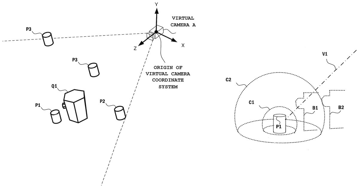
FIG. 3is a diagram schematically showing an arrangement of a plurality of objects located in the virtual space and a conceptual camera (the virtual camera) which is set for generating an image including these objects.
Specifically, a plurality of player characters P1to P4and a non-player character Q1are located in a predetermined plane (hereinafter, referred to as a field) within the virtual space. A virtual camera A is set at such a position that the field is seen down obliquely therefrom. For the virtual camera A, various parameters for performing the perspective transformation process (e.g., a parameter representing the angle of view of a lens, and the like) are set by the game system1.
It is noted that for simplification of explanation, the above field is a plane, but the shape is not intended to be limited to the illustrated one and may be any curved surface as long as a plurality of objects can be located therein. In addition, the type and number of the located virtual objects are as described above, but are not intended to be limited to the settings and may be other settings. Further, inFIG. 3, each virtual object is shown in a simplified shape (a circular cylinder or the like), but its shape is not intended to be limited to the illustrated one and may be a more complicated shape (e.g., a human-shaped virtual object).
Each of a plurality of players (four in this embodiment) who use the game system1is assigned one of operable player characters (the player characters P1to P4in this embodiment). Each player can operate the controller7held by the player, to control movement of the assigned player character in the field.
The game system1generates an image (display image) which represents the virtual space including these virtual objects and is to be rendered on the monitor2, in accordance with the settings of the virtual camera A. InFIG. 3, with the player characters P1to P4and the non-player character Q1, the virtual camera A is located in the world coordinate system. The game system1allows the player characters P1to P4to move within a predetermined range such that the player characters P1to P4are put within the display image. Specifically, the player characters P1to P4and the non-player character Q1are located, for example, so as to be included in a “viewing frustum” based on a virtual camera coordinate system which is set for the virtual camera A. The world coordinate system and the virtual camera coordinate system can be transformed to each other by appropriate coordinate transformation.
The viewing frustum is defined on the basis of a field of vision (FOV) and the distance between a near clip plane and a far clip plane designated by Z coordinates of the virtual camera coordinate system. It is noted that these clip planes and the like are omitted inFIG. 3.
[3.2. Description of Illustrative Image Processing]
The non-player character Q1may be located on the near clip plane side of the player character P1and at such a position as to hide a portion or the entirety of the player character P1from the virtual camera A.
Conventionally, when the perspective transformation process is performed under this condition, for example, the player cannot recognize the player character P1in an image displayed on the monitor2due to presence of the non-player character displayed on the near side of the player character P1. In addition, even when the player recognizes the position of the player character P1, the player cannot recognize, from the image, the shape of a portion of the player character P1which is hidden by the non-player character Q1.
In the game system1according to the illustrative embodiment, the following processing is performed in order to solve this problem. The processing will be described with reference toFIG. 4Aand the subsequent drawings.
FIG. 4Ais an enlarged schematic diagram of a region including the non-player character Q1and the player character P1in the arrangement illustrated inFIG. 3. In this example, a model representing the non-player character Q1is a virtual object of a generally hexagonal column shape and has a projection on a side surface thereof. In this arrangement, the projection extends toward the player character P1. Although described later, the non-player character Q1has another model as a model for representing it, and a set of these two models is handled as a model for representing the non-player character Q1in the game system1.
FIG. 4Bis a schematic diagram of wire frame models which are shown to facilitate the understanding of the outer shapes of the virtual objects shown inFIG. 4A.FIG. 4Bis a diagram conveniently shown to facilitate a description regarding the positional relationship between and shapes of the virtual objects shown inFIG. 4A, and is not an example of a display image.
In the game system1, a third person viewpoint, specifically, such a viewpoint for perspective transformation that the field is seen down from the virtual camera A, is set. For the convenience sake, a case will be described where such a third person viewpoint that the two virtual objects are observed from the virtual camera A in the direction of an arrow shown inFIG. 4Ais set.
When rendering is performed on the basis of the third person viewpoint, a display image is generated in which the player character P1is hidden behind the non-player character Q1as shown inFIG. 4C.FIG. 4Cis a diagram schematically showing a state where the non-player character Q1is seen from the virtual camera A and the player character P1is hidden behind the non-player character Q1and cannot visually be recognized, when these two virtual objects are observed from the virtual camera A in the direction of the arrow shown inFIG. 4A. It is noted that even when the non-player character Q1is displayed so as to be translucent in this positional relationship, it is difficult to recognize the outer shape of the non-player character Q1on the projection side.
FIG. 4Dis a schematic diagram of wire frame models corresponding to the virtual objects shown inFIG. 4C, which are shown to facilitate the understanding of the outer shapes of the virtual objects.FIG. 4Dis a diagram conveniently shown to facilitate a description regarding the positional relationship between and the shapes of the virtual objects shown inFIG. 4C, and is not an example of a display image.
FIG. 5is a schematic diagram for illustrating image processing performed on the non-player character Q1when the two virtual objects are located in this positional relationship.
The image processing described here is image processing performed when a player character such as the player character P1and the non-player character Q1are located in such a positional relationship that the player character is hidden by the non-player character Q1and cannot visually be recognized (hereinafter, referred to as a hiding relationship).
The model of the non-player character Q1is defined as a set of a model which is normally rendered in opaque color and represents an object corresponding to a structure of a substantially hexagonal column shape (hereinafter, referred to as a sub-object1for the convenience sake) and a model which represents an object corresponding to an edge of the structure shown as the sub-object1or at least a portion of the edge (hereinafter, referred to as a sub-object2for the convenience sake).
A model which represents the non-player character Q1and is normally recognized by the player during the game processing is a model of a structure having a projection on one side surface of a hexagonal column, namely, the sub-object1, as schematically shown inFIG. 4A.
In the case where the hiding relationship is not established, the structure as the non-player character Q1is rendered in opaque color and an image representing the appearance thereof is generated (the upper-left diagram ofFIG. 5). Thus, in an image captured from the virtual camera A (a display image which is to be finally displayed on the monitor2and obtained as a result of the perspective transformation process), each surface of the structure is opaque, and a scene on the far clip plane side of the structure in the virtual space is hidden by the structure. It is noted that in the upper-left diagram ofFIG. 5, the hidden player character and the line of the hidden surface of the non-player character are indicated by broken lines, but these broken lines are conveniently shown to facilitate understanding and are not actually displayed when rendering is performed in opaque color.
The relative positional relationship between the player character P1and the non-player character Q1depends on the progress of the game and an input operation performed by the player, and changes with time.
When the positional relationship between the player character P1and the non-player character Q1becomes the above hiding relationship (e.g., in the case illustrated inFIG. 3) during its changing, predetermined image processing is performed on the non-player character Q1.
The image processing makes it easy for the player to recognize the position of the player character P1operated by the player and the shape of the non-player character Q1that the player character P1faces in the virtual space.
A specific determination as to whether or not the hiding relationship is established may be performed, for example, by determining whether or not a ray along a line of sight from the virtual camera A to the player character P1intersects the non-player character Q1(an intersection determination). On the basis of a result of such a determination, the game system1can determine that the hiding relationship is established, when the ray intersects the non-player character Q1. It is noted that although described later, the method of this hiding determination is not limited to this example.
When the hiding relationship is established, the sub-object1is rendered as a translucent virtual object. In other words, the game system1renders the sub-object1so as to take an alpha value which is previously set or dynamically set for the sub-object1(and corresponds to a translucent state), to generate an image corresponding to the model of the translucent sub-object1. The translucent sub-object1allows a virtual object (e.g., the player character P1) or the like, located on the far clip plane of the sub-object1, to be seen therethrough to be visually recognized by the player. It is noted that when rendering a model located on the far side (the far clip plane side) of the translucent model, a depth test is performed and this model is rendered prior to the translucent model present on the near side (the near clip plane side).
Further, when the hiding relationship is established, only a portion of the sub-object2of the non-player character Q1which portion meets a predetermined condition is represented in an image which is to be finally displayed on the monitor2.
The sub-object2is a virtual object which corresponds to the edge of the structure shown as the sub-object1or at least a portion of the edge (the upper-right diagram ofFIG. 5). It is noted that in the upper-right diagram ofFIG. 5, the position of the player character is shown by a broken line to facilitate understanding. Specifically, for example, the sub-object2can be defined as a model obtained by mapping a texture, which is transparent except for a portion at and near the edge (the boundary between surfaces), to a polygon model which is substantially the same in shape as the sub-object1. In the upper-right diagram ofFIG. 5, the sub-object2obtained thus is schematically shown (the background is conveniently darkened in view of ease of understanding the features thereof).
The above predetermined condition which is to be met is, for example, the following condition. The condition is defined on the basis of the relationship between: a line-of-sight vector ekwhich is directed from the origin of the virtual camera coordinate system (an orthogonal coordinate system composed of three axes, an X axis, a Y axis, and a Z axis; seeFIG. 1) set for the virtual camera A (a viewpoint) to a polygon k constituting the sub-object2; and a normal vector nkwhich is defined for each polygon constituting the sub-object2(k=1, 2, 3, . . . ; k is an illustrative number for identifying each polygon constituting a model). This relationship will be described with reference toFIG. 6Aand the like.
FIG. 6Ais a schematic diagram showing a normal vector nkdefined for a polygon k constituting the model of the non-player character Q1. A normal vector nkwhich is perpendicular to a surface defined by vertices which define this polygon is defined. Here, as an example of a primitive figure used in the game system1, a polygon (a triangular polygon) is shown. However, the usable primitive figure is not limited to the example of this polygon. Typically, a surface which is defined with a designation order of the vertices constituting the polygon which designation order is a counterclockwise order is set as a front surface, and the normal vector ekis designated as a vector orthogonal to the surface, but is not limited to this example.
FIG. 6Bis a diagram schematically showing the angle θ formed between the vector ekand an arbitrary normal vector nk. The angle θ is defined by the inner product (ek, nk) of the vectors ekand nkas follows.
(ek,nk)=|ek∥nk|cos θ
The information processing section of the game system1can determine whether or not to set the polygon constituting the sub-object2as a target to be displayed on the monitor2, in accordance with the value of the inner product. Here, when both vectors are normalized, the value of the above inner product is a value of −0.1 to 1.0. Thus, it is possible to set front and back of the polygon by evaluating the value of the inner product (or the sign thereof).
Here, a case will be described where the sub-object2is a model obtained by mapping a texture, which is transparent except for a portion at and near the edge, to a polygon model which is substantially the same in shape as the sub-object1.
In this case, the direction of the normal vector defined for each polygon constituting the sub-object1and the direction of the normal vector defined for a polygon which constitutes the sub-object2and is located in corresponding relation to this polygon constituting the sub-object1are the same.
The sub-object2is rendered such that a portion thereof is displayed which corresponds to a surface which can be evaluated as a hidden surface in the sub-object1. When the player character P1is located on the far side of the non-player character Q1so as to be hidden from the virtual camera A, rendering is performed such that a surface is displayed which includes the surface of the sub-object2that the player character P1faces. In other words, the game system1can set the sign of an inner product value which a polygon to be displayed has to have, for each polygon of the model of the sub-object2such that the sign is opposite to that for the sub-object1. And the game system1can render the sub-object2based on the setting. Then, the sub-object1and the sub-object2are rendered so as to substantially overlap each other, in view of the depth test. Thus, it is possible for the player to recognize the position of the player character P1hidden behind the non-player character Q1as well as the shape of the non-player character Q1on the back side (the shape on the player character P1side).
A method for distinguishing a displayed portion of the non-player character Q1from a portion of the non-player character Q1which is not displayed, will be described in more detail.
FIG. 4Dis a diagram schematically showing a wire frame obtained by extracting the edge portion of the sub-object1(seeFIG. 4C) of the non-player character Q1, and the player character P1located on the far side of the wire frame. An edge A1-B1on one side surface on the far clip plane side (referred to as a side surface β1) in the non-player character Q1is focused on. In addition, of edges parallel to the edge A1-B1, an edge on a side surface (referred to as a side surface β2) which faces the surface including the edge A1-B1is referred to as an edge A2-B2.
In this positional relationship, the angle formed between a normal vector which is set for a polygon on the side surface β1and a normal vector which is set for a polygon on the side surface β2is π. Thus, when a normal vector nk, which is defined for a polygon k on the side surface β1, and a vector ekare directed in the same direction, the value of the inner product thereof is positive. At that time, the value of the inner product of a normal vector nm, which is defined for a polygon nmon the side surface β2, and a vector emis negative. When it is defined that of the polygons of the sub-object2, only polygons having a positive inner product value are displayed, a polygon corresponding to the edge A1-B1is displayed and a polygon corresponding to the edge A2-B2is not displayed.
Therefore, in the example ofFIG. 5, in the sub-object2shown in the upper-right diagram, the portion corresponding to the edge A1-B1is displayed, and the portion corresponding to the edge A2-B2is not displayed. Since the model representing the non-player character Q1is defined as a set of the sub-object1and the sub-object2, the display form of the final model is as shown in the lower diagram ofFIG. 5. It is noted that for simplification of explanation, a portion of the sub-object2other than the above two edges is omitted in the lower diagram ofFIG. 5.
As described above, when the positional relationship with the non-player character Q1which changes with the progress of the game meets a predetermined condition (e.g., when the hiding relationship is established), the game system1performs a transparent process on the sub-object1of the non-player character Q1. The game system1also sets only polygons of the sub-object2which represent the shape of a portion which is hidden when seen from a viewpoint that is the third person viewpoint, as a target to be displayed (e.g., by performing a determination on the basis of the inner product value of a line-of-sight vector and a normal vector of a polygon).
Then, the game system1generates an image in which the model of the sub-object1on which the transparent process has been performed and the portion of the sub-object2corresponding to the shape of the model which portion is determined as a displayed target are displayed so as to be superimposed on each other.
Another example of the sub-object2is shown inFIG. 6C. Specifically, a non-player character having an outer shape corresponding to the shape of the sub-object1is shown in the upper diagram ofFIG. 6C, and a sub-object (corresponding to the sub-object2; hereinafter, referred to as a sub-object2′) set for the non player character in the upper diagram ofFIG. 6Cis shown in the lower diagram ofFIG. 6C.
The sub-object2′ is a sub-object which is generated for a virtual object (the upper diagram) having a projection shape in the outside thereof when observed from the third person viewpoint and which corresponds to an edge on the back surface which is not seen from the viewpoint.
The processing performed on the non-player character Q1in the above image processing when visual recognition of the player character is obstructed by the non-player character Q1has been described. Hereinafter, a method for performing predetermined processing on the player character in order to solve a similar problem, will be described.
This processing may be performed together with the above processing performed on the non-player character or may be performed independently of the above processing.
Hereinafter, as shown inFIG. 3, as an example, a case will be described where the player character P1is located on the far clip plane side of the non-player character Q1and visual recognition of the player character P1is obstructed when seen from the virtual camera A.
The game system1performs the following processing when determining that a positional relationship is established in which the player character P1is located behind the non-player character Q1.
As described above, each of the player character and the non-player character which are located in the virtual space is assigned a model having a predetermined attribute. For each model, a space for excluding the other model may be defined in order for the models to move in such a positional relationship as to prevent the models from entering each other.
In the illustrative embodiment, when the player character P1is located on the far clip plane side of the non-player character Q1and it is determined that the player character P1is hidden when seen from the virtual camera A, the game system1controls the above space for excluding the model as described below, to provide a situation where the player more easily recognizes the player character P1during the game processing.
This will be described with reference toFIGS. 7A and 7B.
FIG. 7Ais a diagram schematically showing a process of determining presence/absence of the hiding relationship which process is performed between the player character P1and the non-player character Q1.
The information processing section of the game system1determines whether or not the positional relationship between the player character P1and the non-player character Q1is the hiding relationship. This determination can be performed by emitting a ray from the virtual camera A to the player character P1and determining whether or not the ray intersects the non-player character Q1(the intersection determination).
InFIG. 7A, a hemisphere C1is a hemisphere which is set for the player character P1to define a region thereof when a determination of collision (between objects) is performed. The hemisphere C1is defined for preventing another object from entering the player character P1. The region defined by the hemisphere C1may have any other shape.
Meanwhile, a dotted line B1schematically indicates the position of and a portion of the outer shape of the non-player character Q1at the above intersection determination. In this example, the projection of the non-player character Q1faces toward the player character P1.
FIG. 7Aillustrates a case where it is determined in the intersection determination that a ray V1intersects the non-player character Q1(located at the position of the dotted line B1). On the basis of the determination, the information processing section enlarges the above hemisphere C1to the size of a hemisphere C2. Then, the information processing section performs a determination of collision with the non-player character Q1on the basis of the hemisphere C2. At that time, since the non-player character Q1has entered the inside the hemisphere C2as shown by the outer shape line that is the dotted line B1, the game system1determines in the determination of collision that the positional relationship between the player character P1and the non-player character Q1is not permitted. As a result of the determination, for example, the game system1moves the non-player character Q1to a position shown by a dotted line B2or moves the player character P1such that a relative positional relationship which is the same as that established as a result of the movement is established, whereby the game system1increases the distance between these two virtual objects.
It is noted that after that, when the relative positional relationship between the player character P1and the non-player character Q1changes with the progress of the game, the information processing section of the game system1dynamically controls the size of the hemisphere for the player character which is used for the determination of collision between the virtual objects, in accordance with a result of the intersection determination at that time. In other words, when it is determined, by the intersection determination based on the ray, that the hiding relationship is not established, the game system1resets the hemisphere C1as a hemisphere used for the determination of collision.
Thus, a situation can be avoided where the player character P1enters deeply into the space below the projection of the non-player character Q1larger than the player character P1such that the player character P1is continuously hidden behind the non-player character Q1and cannot visually be recognized during the game processing. In addition, by dynamically changing the setting of the hemisphere, a region where the virtual objects are moveable can be kept wider when the hiding relationship is not established.
It is noted that when the game system1performs a determination of collision between the player character P1and another player character (e.g., P2), the game system1does not have to change the size of a hemisphere used for the determination of collision of the player character P1(or another player character), in accordance with a result of the determination of intersection with the non-player character Q1. In addition, instead of controlling the hemisphere having a center at the player character P1, a region may be controlled which is defined in the virtual space on the basis of the position of the player character P1and has a shape other than a hemisphere.
With reference toFIG. 7B, a case will be described where the intersection determination based on the ray is not used. Instead of this intersection determination, it may be determined whether or not into a region defined with reference to the position of the player character P1or the non-player character Q1, an opponent for the object used as the reference has entered.FIG. 7Bis a schematic diagram showing a modification ofFIG. 7A. For example, a process is performed in which as shown inFIG. 7B, the hemisphere is enlarged (to the hemisphere C2) when the player character P1enters into a region (a predetermined range extending from a cross mark shown inFIG. 7Btoward the far side of the screen; a region R11inFIG. 7B) defined on the basis of the position of the non-player character Q1(the cross mark indicates the position of the non-player character Q1), and the hemisphere is returned to the original hemisphere (hemisphere C1) when the player character P1moves out of the region.
[4. Details of Game Processing]
Next, the game processing performed in the game system1will be described in detail. First, various data used in the game processing will be described.FIG. 8is a diagram showing various data (including programs) used in the game processing.FIG. 8is a diagram showing main data stored in the main memory (the external main memory12or the internal main memory11e) of the game apparatus3. As shown inFIG. 8, in the main memory of the game apparatus3, a game program100, controller operation data110, and processing data120and130are stored. It is noted that in the main memory, in addition to the data shown inFIG. 8, data used in the game, such as image data of various objects appearing in the game and audio data used in the game, are stored.
A part or the entirety of the game program100is read from the optical disc4and stored in the main memory, at an appropriate timing after the game apparatus3is powered on. It is noted that the game program100may be obtained from the flash memory17or an external device of the game apparatus3(e.g., via the Internet), instead of the optical disc4. In addition, a part of the game program100(e.g., a program for calculating the orientation of the controller7) may previously be stored in the game apparatus3.
The controller operation data110represents operations of the user on the controller7and is outputted (transmitted) from the controller7on the basis of the operations on the controller7. The controller operation data110is transmitted from the controller7, obtained by the game apparatus3, and stored in the main memory. The controller operation data110includes angular velocity data, main operation button data, and acceleration data. It is noted that the controller operation data110includes, in addition to these data, marker coordinate data representing a coordinate calculated by the image processing circuit41of the controller7. In addition, in order to obtain operation data from a plurality of controllers7, the game apparatus3stores the controller operation data110transmitted from each controller7, in the main memory. A predetermined number of items of the controller operation data110from the latest (finally obtained) data may be stored in a chronological order for each controller7.
The processing data120is used in the game processing (main processing) described later. The processing data120also includes data of virtual objects used in the game processing. Each virtual object has, in addition to data which defines an attribute of the virtual object and includes the shape of a model, position information which is defined in the virtual space during the game processing.
The processing data130includes various data used in the game processing, such as data representing various parameters which are set for various objects appearing in the game.
Next, the game processing performed in the game apparatus3will be described in detail with reference toFIGS. 9A and 9B.FIG. 9Ais a main flowchart showing the flow of the game processing performed in the game apparatus3. When the game apparatus3is powered on, the CPU10of the game apparatus3executes a boot program stored in a boot ROM which is not shown, thereby initializing the respective units such as the main memory. Then, the game program100stored in the optical disc4is loaded into the main memory, and execution of the game program100is started by the CPU10. The flowchart shown inFIG. 9Ais a flowchart showing processes performed after the above processes. It is noted that the game apparatus3may be configured to execute the game program100immediately after powered on, or to initially execute a built-in program for displaying a predetermined menu screen after powered on, and then execute the game program100, for example, in accordance with an instruction to start the game which is made by the user performing a selection operation on the menu screen.
It is noted that a process at each step in the flowcharts shown inFIGS. 9A and 9Bis merely an example, and the order of the process at each step may be changed as long as the same result is obtained. In addition, the values of variables are also merely examples, and other values may be used according to need. Further, in the illustrative embodiment, the “information processing section” (an integral of the CPU10, the GPU32, and the like) in the game system1performs the process at each step in the flowcharts. However, only a part of the information processing section may perform processes at some of the steps in the flowcharts, or a processor or a dedicated circuit other than the CPU10and the GPU32may perform processes at some of the steps in the flowcharts.
First, at step1(S1inFIG. 9A; the same correspondence applies to the following steps), the information processing section of the game system1performs an initial process. The initial process is a process of constructing a virtual game space, locating each object (e.g., the player characters P1to P4, the non-player character Q1, and the like) appearing in the game space, locating a virtual camera (e.g., the virtual camera A) at an initial position, and setting initial values of various parameters used in the game processing.
The positions and the orientations of the player characters P1to P4and the non-player character Q1as illustrative virtual objects in the illustrative embodiment are set. Then, the virtual camera A is set in accordance with these settings.
In addition, at step1, an initial process for each controller7is performed. For example, an image for prompting one or a plurality of players to hold the controllers7is displayed on the display screen. As a result of the initial process for each controller7, set variables including parameters which can be outputted by each controller7are set to initial values. When the initial process for each controller7is completed, the information processing section performs a process at step2. Thereafter, a process loop of processes at steps2to6is repeatedly performed every predetermined time (a one-frame time, e.g., 1/60 sec).
At step2, the information processing section obtains operation data transmitted from a plurality of controllers7. Each controller7repeatedly transmits operation data (controller operation data) to the game apparatus3. In the game apparatus3, the wireless communication module18sequentially receives terminal operation data, and the input-output processor31sequentially stores the received terminal operation data in the main memory. In addition, the wireless controller module19sequentially receives each controller operation data, and the input-output processor31sequentially stores the received controller operation data in the main memory. The interval of transmission and reception between the controllers7and the game apparatus3is preferably shorter than the processing time of the game, and is, for example, 1/200 sec. At step2, the information processing section reads out the latest controller operation data110from the main memory. Subsequent to step2, a process at step3is performed.
At step3, the information processing section performs a game control process. The game control process is a process of progressing the game in accordance with a game operation performed by the player.
Specifically, in the game control process in the illustrative embodiment, mainly, in accordance with operations on the plurality of controllers7, the virtual object corresponding to each controller7follows the progress of the game and its internal state (e.g., display form) is sequentially set. Subsequent processes are performed according to these settings. Hereinafter, the game control process will be described in detail with reference toFIG. 9B.
FIG. 9Bis a flowchart showing a defined process (the game control process; steps101to111) corresponding to step3in the flowchart shown inFIG. 9A.
At step101, the information processing section performs a process of setting virtual objects which are to be targets of the game control process. In addition, the information processing section specifies a type of a process to be performed on the virtual objects.
Specifically, the information processing section sets virtual objects which are to be targeted for the processes subsequent to step101, on the basis of the operation information obtained at step2as well as the number and type of player characters operated by the players who use the game system1, the number and type of non-player characters, and presence/absence and content of interaction among these objects which has to be considered in the progress of the game.
In the example shown inFIG. 3, under the condition of the third person viewpoint based on the virtual camera A, the information processing section performs the process at step101on the basis of the setting in which the player characters P1to P4, which are operable by a plurality of players, and the non-player character Q1are located in the virtual space. In this non-limiting example, since four player characters and one non-player characters are present, it is set to perform a determination at the next step102between each of the four player characters and the non-player character. Then, the information processing section proceeds to a process at step102.
At step102, the information processing section performs a process of determining whether or not the “hiding relationship” is established between each player character and the non-player character. In the process, calculation for determining whether or not the “hiding relationship” is established is performed on the basis of position information, in the virtual space, of the virtual objects which are set at step101as the processing targets at step2. When a plurality of virtual objects are present, the information processing section performs this calculation for all the objects between which the hiding relationship can be established.
Specifically, the information processing section performs the determination as to whether or not the hiding relationship is established, as follows. For example, the information processing section performs the calculation for determining presence/absence of the hiding relationship, by determining whether or not a ray along a line of sight from the virtual camera A to the player character P1intersects the non-player character Q1(the intersection determination). As a result of such a determination, when it is determined that the ray intersects the non-player character Q1, the game system1can determine that the hiding relationship is established between the player character P1and the non-player character Q1. Then, the information processing section proceeds to a process at step103.
At step103, the information processing section performs a process of selecting a subsequent process on the basis of a result of the calculation performed at step102. When the hiding relationship is established between the virtual objects which are the processing targets, the information processing section proceeds to a process at step104. On the other hand, when the hiding relationship is not established, the information processing section proceeds to a process at step106.
At step104, the information processing section performs a process of setting a shape for collision determination of the player character, to an enlarged state.
Specifically, when it is determined at step103that the hiding relationship is established between the player character P1and the non-player character Q1, the information processing section sets the hemisphere for collision determination which is set for the player character P1, from the hemisphere C1in a normal state to an enlarged state of the hemisphere C2having a larger radius than that of this hemisphere (seeFIG. 7A). Then, the information processing section proceeds to a process at step105. It is noted that for natural switching, the enlargement from the hemisphere C1to the hemisphere C2may be performed gradually for a predetermined time.
At step105, the information processing section performs setting of the sub-object1of the non-player character Q1to be translucent.
Specifically, as described in the outline of the game processing, the non-player character Q1is defined as a set of an object (the sub-object1) corresponding to a structure rendered normally in opaque color and an object (the sub-object2) corresponding to the edge of the structure shown as the sub-object1or at least a portion of the edge. When it is determined at step103that the hiding relationship is established between the player character P1and the non-player character Q1, the information processing section performs, at step105, setting of the sub-object1of the non-player character Q1to be translucent.
Specifically, the information processing section sets an alpha value which is set for each polygon defined as the sub-object1, to a value which provides translucence. As an example, a case will be described where the alpha value is a value of 0.0 to 1.0, transparence is provided when the alpha value is 0.0, and opacity is provided when the alpha value is 1.0. A state of being “translucent” can be defined as a state obtained when the alpha value is 0.5. In addition, the alpha value may not be provided as a fixed value, and may be set so as to gradually approach a predetermined value with the progress of the game processing. Such setting of the alpha value is illustrative and not limited to this example. Then, the information processing section proceeds to a process at step108.
As described above, when it is determined in the process at step103that the hiding relationship is not established, the information processing section proceeds to a process at step106.
At step106, the information processing section performs a process of setting the hemisphere for collision determination which is set for the player character P1, to its normal state (the hemisphere C1) or performs a process of maintaining its setting. Then, the information processing section proceeds to a process at step107. It is noted that for natural switching, the change to the hemisphere C1may be performed gradually for a predetermined time.
At step107, the information processing section performs setting of the sub-object1of the non-player character to be opaque. Then, the information processing section proceeds to the process at step108.
At step108, the information processing section performs a process of calculating an inner product value which is defined on the basis of each polygon of the sub-object2of the non-player character.
Specifically, the inner product value is defined on the basis of the relationship between: a three-dimensional vector ekwhich is directed from the origin of the virtual camera coordinate system (the orthogonal coordinate system composed of three axes, an X axis, a Y axis, and a Z axis; seeFIG. 1) set for the virtual camera A (the viewpoint) to a polygon k (constituting a model); and a normal vector nkwhich is defined for the polygon k ([k=1, 2, 3, . . . ]; the index k is an illustrative number for identifying each polygon constituting the model).
Here, as described above, the sub-object2is a virtual object corresponding to the edge of the structure shown as the sub-object1or at least a portion of the edge. The information processing section calculates an inner product value of the three-dimensional vector ekand the normal vector nkfor each polygon k constituting the object. Then, the information processing section stores the result of the calculation in the storage area of the game system1. Then, the information processing section proceeds to a process at step109. The inner product value is used when an image to be displayed (on the monitor2) is generated at subsequent step4.
At step109, the information processing section performs a determination of collision between the non-player character Q1and the player character P1. Then, the information processing section proceeds to a process at step110. The information processing section determines whether or not a space which is defined by the hemisphere C1or C2and occupied by the player character P1overlaps a space which is previously set and occupied by the non-player character Q1. For this determination, a general collision determination method can be used. Then, the information processing section stores a result of the collision determination in the storage area of the game system1and proceeds to a process at step110.
At step110, when additional setting has to be performed for image processing of the virtual objects, the information processing section performs the additional setting. For example, in accordance with a result of the determination at step109, the information processing section can appropriately move the positions, in the virtual space, of the virtual objects which are the determination targets, to reset their positions. Then, the information processing section proceeds to a process at step111.
At step111, the information processing section performs a process of determining presence/absence of the hiding relationship, and determining, in accordance with the determination, whether or not there is another virtual object for which settings for image processing have to be changed. As a result of the determination, when there is such another virtual object (YES at step111), the information processing section proceeds to the process at step102. When there is not such another virtual object (NO at step111), the information processing section ends the game control process and returns to a process at step4(FIG. 9A).
Referring back toFIG. 9A, processes at subsequent steps will be described.
At step4, the information processing section performs a process of generating an image which is to be displayed on the monitor2, on the basis of the results of the determinations and setting performed in the process at step3(steps101to111inFIG. 9B).
Specifically, the information processing section renders a display image on the basis of the positions of the virtual objects present in the virtual space and the setting performed at step3for the virtual objects. In the non-limiting example shown inFIG. 3and the like, the information processing section performs a perspective transformation process on the basis of the virtual camera coordinate system having an origin at the position of the virtual camera A, to generate an image including the player characters P1to P4and the non-player character Q1. It is noted that in the rendering, the information processing section performs a depth test in which depth information (e.g., Z value) is compared per pixel.
Here, with regard to the player character P1located on the far clip plane side of the non-player character Q1, its sub-object1is rendered so as to be translucent. Thus, even when the hiding relationship is established between these objects, the player who views the display image can recognize the position of the player character P1.
Further, the information processing section displays a portion of the sub-object2of the non-player character which portion meets a predetermined condition, together with the sub-object1of the non-player character in a superimposed manner. The predetermined condition is a condition which is defined on the basis of the inner product value of: a normal vector which is set for the polygon of the portion among each polygon constituting the sub-object2; and a line-of-sight vector from the virtual camera A.
Specifically, the sub-object2is rendered such that a portion thereof corresponding to a surface which is evaluated as a hidden surface in the sub-object1is displayed. When the player character P1is located on the far side of the non-player character Q1so as to be hidden from the virtual camera A, rendering is performed such that a surface including the surface of the sub-object2that the player character P1faces is displayed. In other words, the game system1sets the sign of an inner product value which a polygon to be displayed has to have, for each polygon of the sub-object2such that the sign is opposite to that for the sub-object1, and renders the sub-object2.
At step5, the information processing section displays the image generated at step4, on a display section (e.g., the monitor2) of the game system1. Then, the information processing section proceeds to a process at step6.
At step6, the information processing section determines whether or not to end the game processing being performed in the game system1. When it is determined to continue the game processing (NO at step6), the information processing section returns to the process at step2. On the other hand, when it is determined to end the game processing (YES at step6), the information processing section completes the main processing.
OTHERS
In the illustrative embodiment described above, the game processing is executed by the game system1. However, in another illustrative embodiment, a plurality of information processing apparatuses, included in a computer system, which can communicate with each other may share the execution of the information processing.
It is noted that in the case where the game processing program and the like are used on a general-purpose platform, the game processing program may be provided under the condition that a standard program module provided on the platform is used. It is understood that even if a function corresponding to such a module as described above is excluded from the game processing program, the resultant game processing program substantially corresponds to the original game processing program as long as the module complements the excluded function.
It is noted that the aforementioned image processing performed on the non-player character Q1is not prevented from being applied to a player character according to need.
The game processing system and the like illustrated in the illustrative embodiment are useable to make it easy for the player to recognize the state of the virtual object during the game processing.
While certain exemplary game processing systems, game processing methods, game processing apparatuses, and computer-readable storage media having game processing programs stored therein have been described herein, it is to be understood that the appended claims are not to be limited to the game processing systems, the game processing methods, the game processing apparatuses, and the computer-readable storage media disclosed, but on the contrary, are intended to cover various modifications and equivalent arrangements included within the spirit and scope of the appended claims.
Claims
- A game system for performing game processing for a virtual space, the game system comprising: an operation processing section configured to control a player character in a virtual space on the basis of an operation of a player;a condition determination section configured to perform a determination of whether or not a positional relationship between the player character and a predetermined object meets a predetermined condition, wherein the predetermined condition is a condition of the predetermined object obscuring at least some of the player character based on the viewpoint from a virtual camera of the virtual space;at least one processor configured to adjust a collision boundary or region associated with the player character in accordance with the predetermined object obscuring at least some of the player character based on the viewpoint from a virtual camera of the virtual space;and an adjacency processing section configured to perform collision processing in accordance with the adjusted collision boundary or region associated with the player character.
- The game system according to claim 1 , wherein the condition determination section is further configured to determine whether or not the player character is close to the predetermined object.
- The game system according to claim 1 , further comprising a transparent processing section configured to increase transparency of the object on the basis of the performed determination.
- The game system according to claim 1 , further comprising a collision determination section configured to determine that a collision has occurred between the player character and the object in accordance with the performed collision processing.
- The game system according to claim 4 , wherein the collision boundary or region is a predetermined shape, and the adjusted collision boundary or region increases a size of the predetermined shape.
- The game system according to claim 1 , wherein the predetermined object is an enemy object.
- The game system according to claim 1 , wherein the operation processing section is further configured to control a plurality of player characters on the basis of operations of a plurality of players.
- A game processing method for performing game processing on a processing system that includes at least one processor, the game processing method comprising: controlling a player character in a virtual space on the basis of an operation of a player;determining, via the processing system, whether or not the player character is at least partially hidden by a virtual object of the virtual space based on a view from a virtual camera;performing collision determination processing to determine whether or not a collision occurs with respect a first collision area associated with the player character based on determining that the player character is at least partially hidden by the virtual object;and performing collision determination processing to determine whether or not a collision occurs with respect to a second collision area associated with the player character in accordance with determining that the player character is not at least partially hidden by the virtual object, where the second collision area is different from the first collision area.
- The game processing method according to claim 8 , wherein the determining includes determining whether or not the player character is close to the virtual object.
- The game processing method according to claim 8 , further comprising increasing transparency of the object on the basis of determining that the player character is at least partially hidden by the virtual object.
- The game processing method according to claim 8 , further comprising determine that a collision has occurred between the player character and the virtual object in accordance with performed collision determination processing.
- The game processing method according to claim 11 , wherein first collision area and the second collision area are predetermined shapes with the first collision area being larger in size than the second collision area.
- The game processing method according to claim 8 , wherein the virtual object is an enemy object.
- The game processing method according to claim 8 , wherein the controlling includes a plurality of player characters that are controlled on the basis of respective input operations from a plurality of players.
- A non-transitory storage medium storing computer executable instructions for use by a processing system that includes at least one processor, the stored instructions comprising instructions, when executed by the processing system, configured to: display a view, to a display device, of a virtual game space that includes the first virtual object and another virtual object as viewed from a virtual camera;determine that the first virtual object is at least partially obstructed, as viewed from the virtual camera, by the another virtual object located in the virtual game space;adjust a collision boundary or region that is associated with the first virtual object located in the virtual game space in accordance with the determination that the first virtual object is at least partially obstructed;and perform collision determination processing in accordance with the adjusted collision boundary that is associated with the first virtual object.
- The medium of claim 15 , wherein: the first virtual object is a first user controlled virtual object that is controllable by user provided input, the another virtual object is a non-user controlled object, and the collision boundary or region that is associated with the first user controlled virtual object is not adjusted based on a second user controlled object obstructing the first user controlled virtual object as viewed from the virtual camera.
- A game processing method for performing game processing on a processing system that includes at least one processor, the game processing method comprising: controlling a player character in a virtual space on the basis of an operation of a player;determining, via the processing system, whether or not the player character is at least partially hidden by a virtual object of the virtual space based on a view from a virtual camera;performing collision determination processing with respect to a first collision area, which is associated with and applied in accordance with movement of the player character, based on determining that the player character is at least partially hidden by the virtual object;and performing collision determination processing with respect to a second collision area, which is associated with and applied in accordance with movement of the player character, based on determining that the player character is not at least partially hidden by the virtual object, where the second collision area is different from the first collision area.
Disclaimer: Data collected from the USPTO and may be malformed, incomplete, and/or otherwise inaccurate.